Article

Influence of Deposition Parameters on Hardness Properties of InconelTM 718 Processed by Laser Powder Bed Fusion for Space Applications

1
DIMEAS, Politecnico di Torino, Corso Duca degli Abruzzi 24, 10129 Torino, Italy
2
Italian Space Agency, Via del Politecnico, 00133 Roma, Italy
3
DISAT, Politecnico di Torino, Corso Duca degli Abruzzi 24, 10129 Torino, Italy
4
Sòphia High Tech, Via Malatesta 30A, 80049 Somma Vesuviana, Italy
*
Author to whom correspondence should be addressed.
J. Manuf. Mater. Process. 2023, 7(1), 36; https://doi.org/10.3390/jmmp7010036
Submission received: 24 December 2022 / Revised: 26 January 2023 / Accepted: 28 January 2023 / Published: 1 February 2023
(This article belongs to the Special Issue Precision Additive Manufacturing Processes)

Abstract

:
InconelTM 718 is widely used for commercial application in aerospace industry and additive manufacturing process allows for versatile design and manufacturing opportunities. In the present research, the results of a wide experimental campaign run on additive manufactured InconelTM 718 specimens obtained with different processing parameters are presented. In particular, the influence of process parameters (for both vertical and horizontal planes with respect to the building direction) on the hardness properties are investigated. A further investigation is performed on the optimal hardness testing procedure for additive manufacturing. The research is extended to as-built and heat-treated specimens. The new insight gained is that the orientation of the printing direction with respect to indentation direction can be responsible for scattering in hardness measurements and indentation size effect. As-built specimens show a strong anisotropy for in-plane and growth directions and an increment of hardness with respect to increasing energy density. The difference between hardness value with respect to the energy density and the measurements scattering are reduced by the heat treatment. A careful handling of hardness data is required when dealing with additive manufactured materials.

1. Introduction

Among the several process characterizing additive manufacturing (AM), the Laser Powder Bed Fusion (LPBF) process is widely used for mechanical component manufacturing. In this process, the quality of the finished part is directly linked to a high number of parameters [1]. The most common parameters used to optimize the process are the hatching distance, the scanning speed, and the laser power. All these parameters influence the volumetric energy density and then the mechanical properties and the surface roughness of the components [1]. Energy density (ED) and scanning strategy influence the temperature profile during the building process and consequently the part hardness. For the specific case of InconelTM 718, the heating and cooling processes during the LPBF deposition increase the hardness of AM more than conventional processes [2]. If process parameter setting is not optimized, some typical defects are generated in the part. For example, a low hatch distance results in porosities, and a low laser power associated with a high scanning speed and large layer thickness usually causes the so-called balling phenomenon [1].
LPBF additive manufacture of aerospace components is applied using several nickel alloys, most commonly with InconelTM 625 and 718. Nickel alloys are often selected because of their capability to withstand extreme temperatures while maintaining good mechanical strength. A further pro of these materials is a resistance to creep and corrosive environments. LPBF is now a consolidated technology for nickel alloys obtained by means of LPBF, as they are operative in flight [3], while many others will be developed for future use.
A typical example of an aerospace component under development is the propellant injector of liquid rocket engines. For these kinds of components, InconelTM 718 is often the best choice due to its capability to guarantee the best mechanical performances at high temperature, e.g., [2,4,5,6]. The complex geometry of injectors is suited for AM process. AM can greatly reduce part count and joints associated with multi-element injectors, as they may be composed of very few AM parts. AM can present some specific disadvantages for injector fabrication, such as low resolution in terms of mechanical tolerances and excessive surface roughness. Research progress is gradually alleviating these weaknesses. In [7], an interesting overview of InconelTM 718 application in aerospace component manufacturing is presented.
Another current disadvantage in injector manufacture, when using AM processes based on powder feedstock, is the necessity to remove residual powder from internal passages of limited access. Removing all the powder prior to any heat treatment (even stress relief) is necessary because trapped powder be sintered, making it difficult or impossible to remove later.
A problem related to the design and use of components obtained by means of AM is that the estimation of structural behavior as a material mechanical property is strongly dependent on the AM process [8,9]. Traditional mechanical characterization can provide unreliable information as, for example, specimen scale [10] and building direction [3,10] can affect properties as process parameters do. A simple, low cost, and common estimation of mechanical properties is obtained by means of hardness measurement.
Known as an extrinsic material property, hardness is defined as a measure of the material resistance to plastic deformation when penetrated by an indenter tool [6,11,12]. The hardness test is non-destructive (or semi-destructive) and hardness measure results tend to be linearly proportional with mechanical properties such as Young’s modulus, tensile strength and yield strength [13,14].
In [15], the surface hardness measurements are presented related to conventional fabrication processes [13]. The corresponding procedures are described in Standard EN ISO 6507 [16], while for additive manufacturing a standard is not yet available. In [17], a procedure to measure the material properties of AM materials is proposed. For reliable hardness measurements, the surface finish state is critical. A flat surface is indicated, and, for accurate penetration, the surface roughness must be minimized according to EN ISO 6507. Consequently, the applicability of EN ISO 6507 for testing AM materials is linked to the requirements to meet surface finish specification.
Keist and Palmer [18] demonstrated that the Vickers test hardness procedure can be applied for AM LPBF processed materials as Ti-6Al-4V alloys, but it results in large data scattering due to different phase orientation induced by the AM process.
As already stated, surfaces obtained by means of AM present an irregular and rough aspect, and surface roughness changes according to the investigated surface (side or front with respect to the growth direction). In addition to this, the contour layer is not representative of the bulk material mechanical properties because different process parameters are typically used for the contour and the body. This remarkable difference could cause porosities between contour and bulk areas. These porosities make indentation testing difficult and measures unreliable. Polishing surfaces allow for the removal of this contour layer and reduces its influence on the hardness measurement.
Although technical literature covers different applications of AM applications, a systematic analysis on the applicability of hardness measurements procedures to obtain mechanical properties for AM parts is lacking. In particular, the causes of hardness measure scattering for AM parts and then of the reliability of hardness when applied to AM component are missing.
Starting from a preliminary methodological background related to hardness measurements, the present research aims to present the experimental investigation on the influence of deposition parameters on mechanical hardness structural property of InconelTM 718. A further aim of the investigation is to determine the optimal hardness testing procedure for Inconel AM parts. The investigation is extended to as-built and heat-treated samples.

2. Methodological Background

The historical evolution of hardness measurement definitions and techniques is well documented in literature, among the others in [19].
Meyer [15] gives a technical definition of hardness based on the projected area of the impression. The average pressure is assumed as the measure of hardness, referred to as the Meyer hardness. The Meyer test is less sensitive to the applied load [20]. Meyer also proposed an empirical relation between the applied load and the size of the indentation (Equation (1)), called Meyer’s law [15], whose range of validity is related to material properties:
L = k d n
where d is the indenter diameter (mm), n   is a material constant related to strain hardening of metal, and k is a material constant expressing the resistance of metal to penetration.
Mayer’s law is implemented in the Vickers hardness test which measures the diagonal of the square plastic indentation obtained by a diamond pyramid indenter pressed against the investigated surface with a given load L, after elastic recovery [20]. Rockwell [21] and Brinell [22] hardness tests are characterized by a conical and a spheroidal indenter, respectively. These testing procedures usually require adapting either the load or the indenter with the hardness scale. Consequently, measurements obtained on the same specimens with different procedures cannot be directly compared. On the other hand, the impressions made by the pyramid indenter are geometrically similar and independent of load [18,19].
The correlation between hardness and tensile mechanical properties was investigated by many researchers [14,18,23]. In particular, the UTS and yield strength σy and the hardness H referred to Vickers Standard are generally related by linear relations such as Equations (2) and (3) in the empirical model of Cahoon [24]:
σ y = H 2.9 0.1 n
UTS   = H 2.9 n 0.217 n
where H is the measured hardness and n the strain hardening exponent. This model fits the results of ferritic steels for temperature ranges from room temperature up to 400 °C.
The Pavlina empirical model [14] is obtained from diamond pyramid hardness tests run at room temperature on a wide range of steels. The proposed least square linear data regression gives the following empirical Equations (4) and (5) for yield strength sy and UTS, respectively:
σ y = 90.7 + 2.876   HV
U T S = 99.8 + 3.734   HV
where sy is in (MPa), and hardness HV is measured in Vickers scale.
Another very simple empirical relation is reported in Equation (6) and it is widely diffused in literature [25] for materials which do not experience a work-hardening behavior:
HV 3 σ y
In the ASM handbook [19], the same relation is provided between HV and UTS for carbon and alloy steels with different pre-treatments.
Krishna [23] proposes similar linear relations between HV, UTS, and sy for copper alloys, while Keist [18] proposes them for AM titanium alloys. The authors discuss the variability of micro-hardness measurements and present a procedure for hardness data processing to obtain tensile properties despite the measuring scatter. The scattering of data is strongly related to the AM processing and the relation between process parameters and micro-hardness measurements is discussed for AM Ti alloys. Again, an empirical linear relationship between micro-hardness and sy and UTS is observed, suggesting that the relation between mechanical properties and HV is linear and, according to the selected material, the corresponding coefficients are calibrated. Furthermore, the results of [18] show that the linear model also fits AM specimen behavior.
Hardness measurement consist in generating and measuring a plastic deformation on a surface. The reliability of the measure is related to continuity and homogeneity of the deformed material. Continuity and homogeneity of AM material can be assumed according to the scale of observation. Then, the reliability of hardness measurement requires to be discussed.

3. Materials and Methods

3.1. Experimental Design

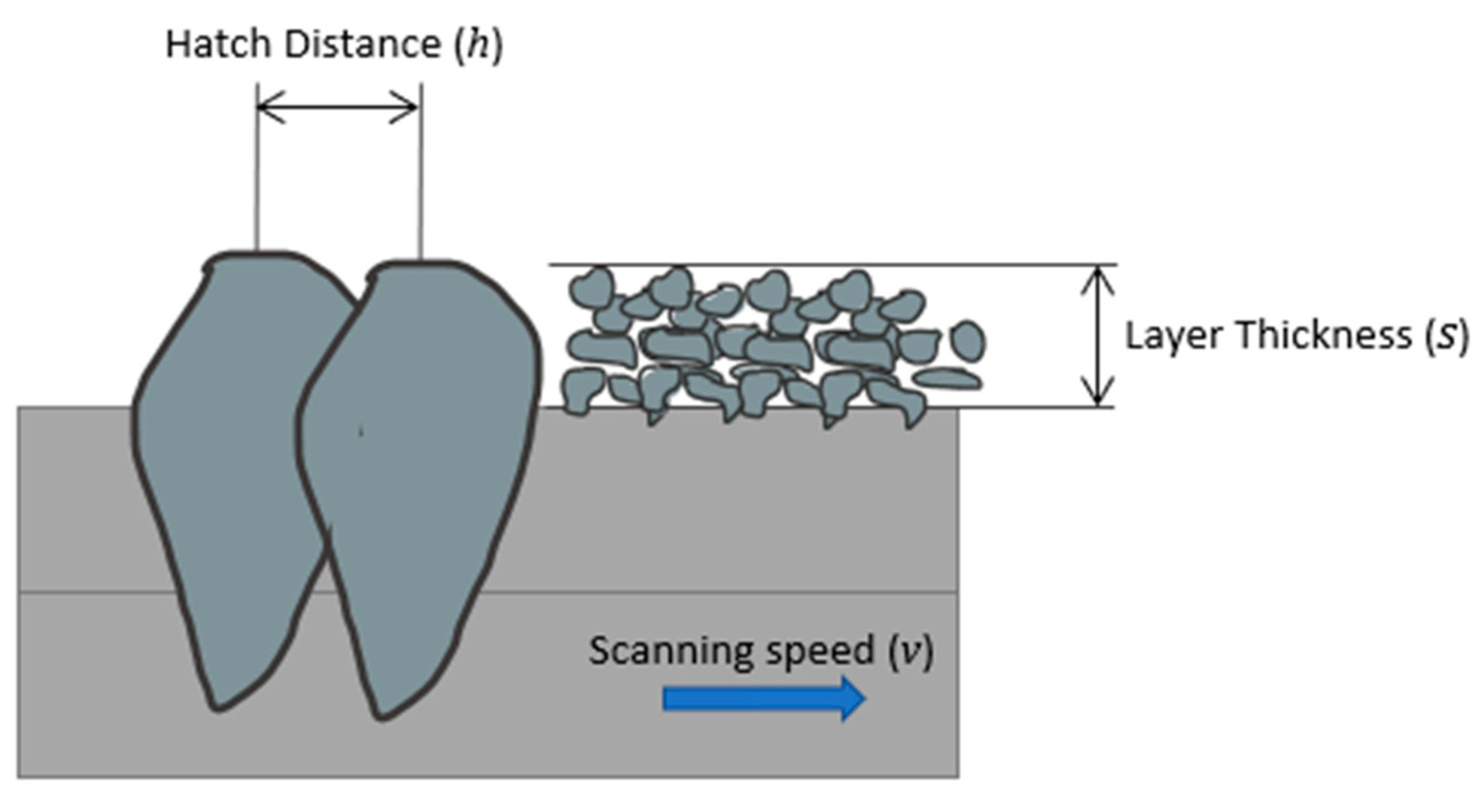
A design of experiment (DOE) was planned to evaluate hardness properties of InconelTM 718 processed by LPBF. LPBF process parameters affect material density and consequently the material properties [26]. It is known that four main parameters can be combined in the energy density ED: laser power P, scanning speed v, layer thickness s, and hatch distance h [27] (Figure 1). The energy density expresses the amount of energy delivered per unit volume of powder deposited and it is related to the material density, porosity, and defect formation mechanism [26]. It is measured in (J/mm3) and it is defined in Equation (7) as follows [28]:
E D = P v · s · h
The same parameter is proposed in [29] where an experimental study is described investigating the relation between ED and surface roughness, number and size of pores and Vickers hardness. In particular, this parameter is indicated when the investigation deals with several process parameters at once. In the present paper, the proposed test planning investigates the influence of the laser power and the scanning speed. The values of the processing parameters explored in the testing plan are centered on the nominal parameters indicated by the printer supplier (for InconelTM 718: P = 192 W and v = 600 mm/s). A larger range of ED variation is explored in [29].
In the present research, the arrangement of specimens on the printing platform was designed for evaluating its influence on the hardness and the material response to seven different energy densities. Hardness was measured on each specimen, and both deposition and growth planes were tested. A micrography analysis was also performed The analysis was applied to as-built and heat-treated specimens to evaluate the effects of a standard thermal treatment [30].

3.2. Materials and Specimens

Twenty-eight specimens, made of InconelTM 718 alloy, were printed by means of a LPBF Concept Laser M2 Series printer, in InconelTM 718 powder. The selected powder is PowderRange 718 by Carpenter Additive (Philadelphia, PA, USA). In Table 1, the SEM-EDS powder average chemical composition from the powder datasheet is reported, while Table 2 summarizes the powder average chemical composition obtained for six powders samples via an EDS point analysis (Figure 2). In Table 3, Table 4 and Table 5, other data from the powder datasheet are reported.
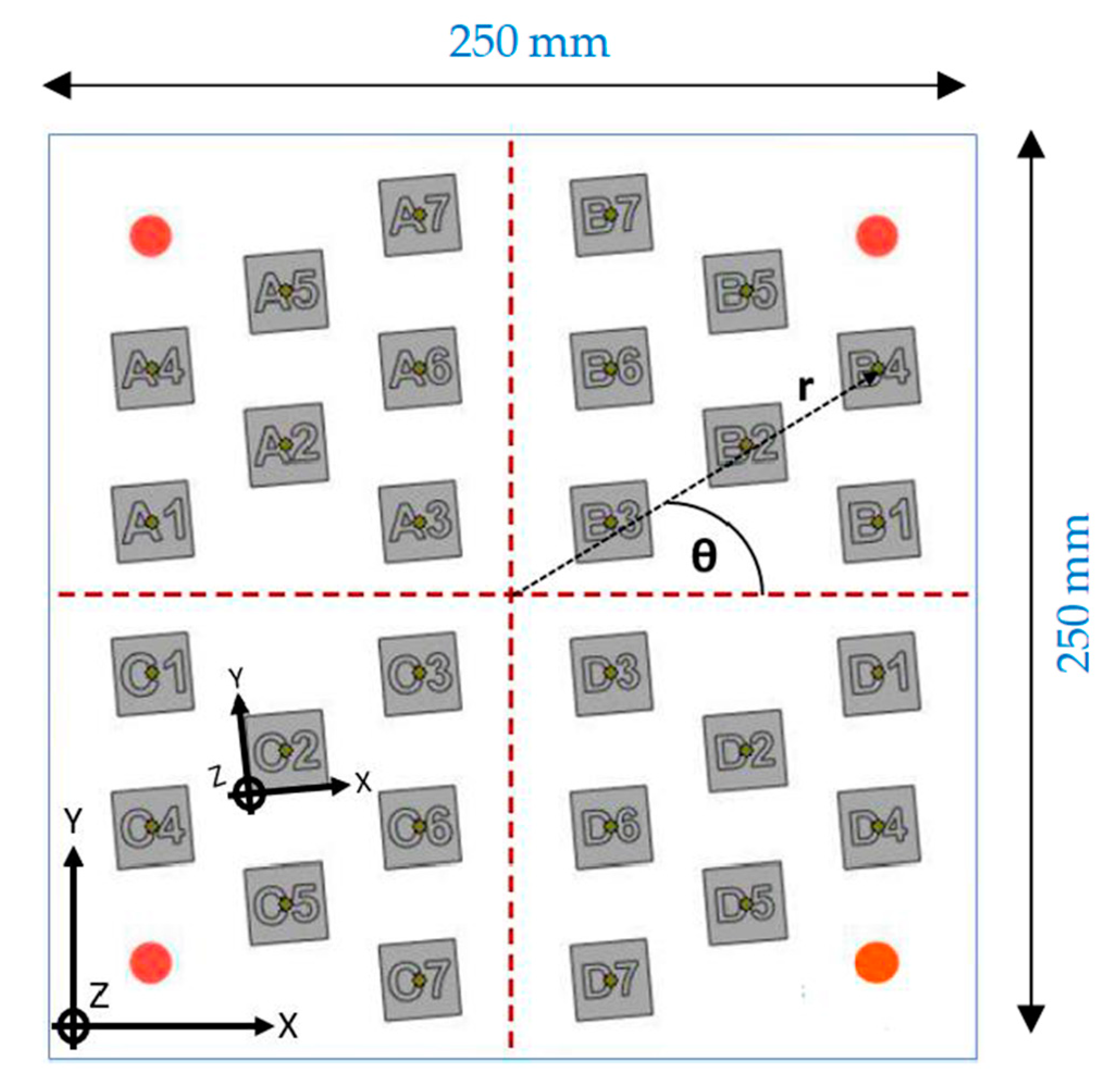
The specimens are cubic, 20 mm edges. The fusion platform is divided in four quadrants with seven specimens in each. Given a polar reference angle θ centered in the center of the platform, this disposition makes it possible to evaluate the influence of the polar angle on the hardness of the specimens (Figure 3). Each cube is rotated by an angle of 15 degree on the building platform with respect to recoating blade, to avoid that the force of the blade could cause the part detachment from the building platform and, in general, to reduce the interaction between the printing items and the recoating blade [31].
Each specimen is named with a letter and a number. Letters A, B, C, and D indicate the four different quadrants of the building platform. The numbers from 1 to 7 refer to the different AM process parameters applied, and the ones named with the same number are positioned at the same distance from the center of the platform. The selected process parameters used for the body and contour of the part are listed in Table 6.
The testing parameters (laser power, scanning speed, and energy density) are reported in Table 7. For compatibility purpose with the material requirements, a pure nitrogen inert gas was used and a silicon coater was used for the powder bed deposition.
As mentioned before, the selected scanning strategies affect the properties of the specimen, because of the different thermal gradients generated. The main scanning strategies include zig-zagging tracks, arrays of parallel stripes, spirals, and contours from the external edges to the center of the part [32,33].
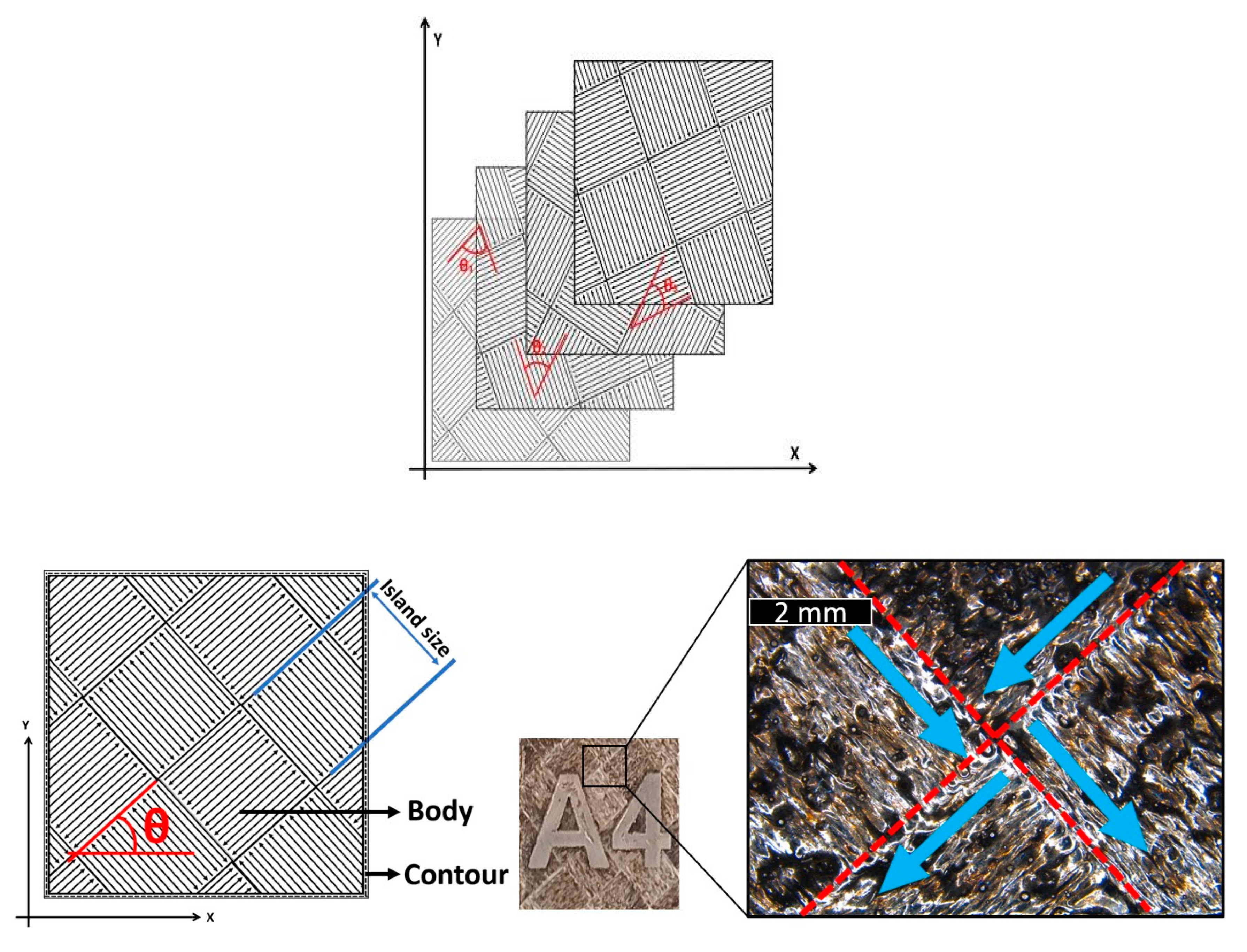
In the present research, the island scanning pattern was applied. The advantages of this strategy are that it shortens the scan vector and reduces the residual stresses in the part [34,35,36]. This strategy divides each layer into smaller islands, scanned in random order, maintaining perpendicular the scanning vectors of the neighboring islands. While depositing subsequent layers, the islands are shifted in both x and y directions [35] of the deposition plane. A scheme of the strategy is reported in Figure 4. A direct link support strategy is employed to link specimens to the fusion platform, without using a dedicated lattice support shape.
InconelTM 718 is a weldable Ni superalloy. Precipitation hardening phases and solid-solution hardening effect improve its strength properties. Precipitates are composed of the refractory metal elements as Nb and Mo in a Ni Cr based γ matrix. Depending on the manufacturing methods and heat treatment, different types of precipitates (γ′, γ″, δ), carbides (MC, M6C, M23C6), and secondary phases can be present in the microstructure. The precipitation of the secondary phases is induced by heat treatment in the temperature range from 620 °C to 760 °C. For such a metallurgical reaction to properly take place, the aging constituents (Al, Ti, Nb) must be dissolved in the matrix [37].
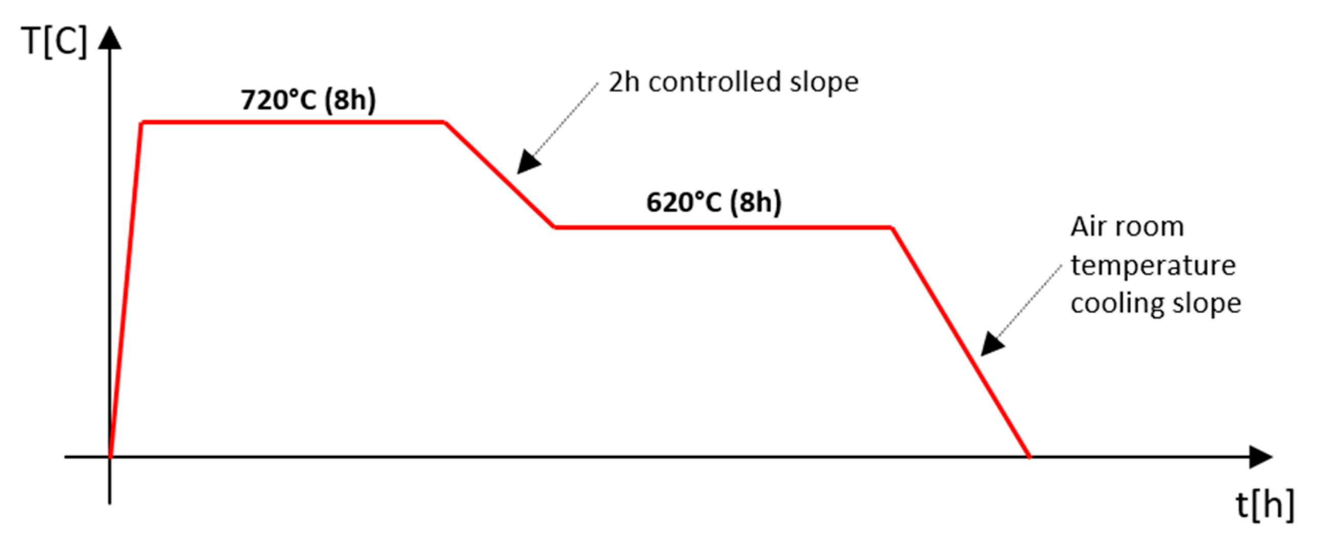
A standard thermal treatment [30], was performed with an industrial oven without pressure and atmosphere controls. The chart presented in Figure 5 shows the temperature vs. time treatment cycle.
Once fabricated, each specimen was removed from the printing platform using a bandsaw. As contour parameters of all specimens do not change, the average roughness parameter is independent from the process parameters of the body (Table 6). The measured average surface roughness Ra on the XZ plane (Figure 5) was 9.6 μm, with a standard deviation of 1.5 μm.
The specimen preparation for hardness measurements was performed by means of machining removal, for XY plane tests of the down-skin (Figure 6) and for the XZ/YZ plane of the contour layer skin.
Mechanical polishing was performed by means of a sander machine (grit size increasing 320, 800, 2500) and water coolant. Then the obtained average surface roughness Ra of the polished specimens is 0.06 μm, with a standard deviation of 0.04 μm. This procedure assures that the hardness analysis is performed with respect to the body material to avoid uncommon behavior due to the contour-skin, up-skin or down-skin, especially after the non-controlled atmosphere heat treatment. The relative density of each specimen is measured with Archimede’s method.

3.3. Hardness Testing

Hardness was measured by means of an Innovatest Nemesis 9000 durometer integrated with the ImpressionsTM tester control and workflow software. Data acquisition was obtained according to standard EN ISO 6507 [38]. The perpendicular surfaces of every sample were tested and five repetitions for each measuring configuration were acquired at room temperature. The average of the five measures on each surface was assumed as the hardness value. Hardness was evaluated in the deposition base plane (XY plane) and the building job direction (Z). Figure 7 shows a schematic representation of the measured surfaces. The difference between bottom, center, and top location of the plane, analyzed with respect to X, Y, or Z axes has not been considered. For the XY plane, the bottom one, close to the platform, was tested, embossing the upper one the specimen id. For the YZ and XZ plane, a random contour one was selected. Different studies reported a homogeneous hardness distribution from the bottom to the top of the specimen with respect to the deposition direction [39]. On the other hand, other studies show that the hardness decreases through the build height [40]. The higher hardness at the bottom of the builds was attributed to enhanced precipitation hardening due to the repetitive heating cycles experienced by the bottom region of the builds during the AM process [41].
The five indentations are located in the center [42] (inside a 5 mm radius circle) of the analyzed surface because of the better stability of the sample while the load is applied.
The impressions made by the pyramid indenter are geometrically similar and independent of load and, according to large literature available on hardness data for InconelTM 718 processed by LPBF technology [43,44,45,46,47,48], the Vickers test was selected.
A preliminary study was performed to determine the measuring load which minimizes the standard deviation linked to the largest available plastic deformation. Tests were run on A1 specimens.

3.4. Micrographic Analysis

A reverse optical microscope was employed for the micrography analysis [16,45,46,47,48,49,50]. The mechanical polishing procedures was used for achieving the target surface quality. In particular, several grit sizes discs with an increasing particles dimension from 800 to 4000 with water coolant were used. After the mechanical procedure, the Keller N° 2 chemical reagent was used. The attacked surfaces were exposed for a total time of 6 s.

4. Results

4.1. Preliminary Measuring Load Assessment

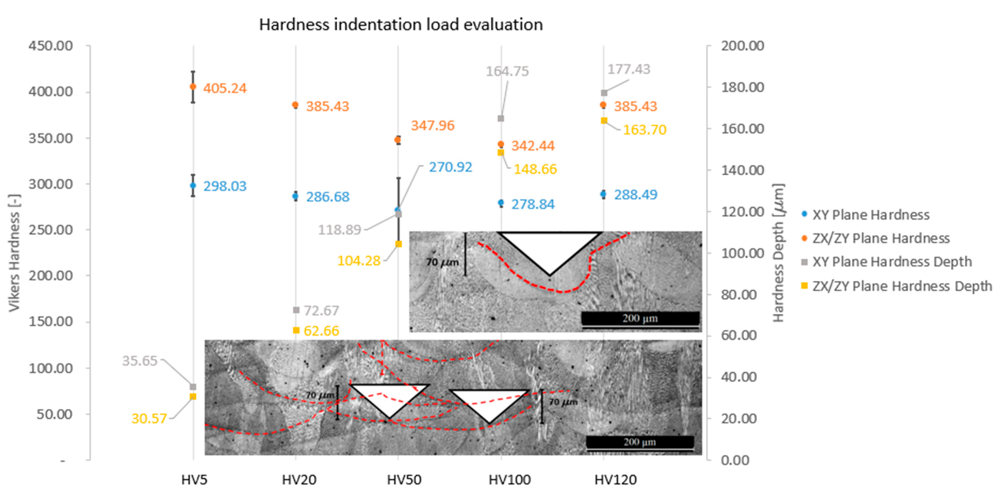
Preliminary hardness testing results are plotted in Figure 8. In this plot, the hardnesses measured in XZ/XZ and XY planes are reported for the same specimens A1. In the same plot, the data scattering, i.e., standard deviation for hardness measurements, is reported. It can be observed that, by increasing the load, the scattering decreases. HV20 has been identified as the optimal method for hardness properties when optimizing parameter are low standard deviation in hardness measurements on both surfaces and a good compromise applied load which is between the lowest HV5 and the highest HV120 [49]. A similar result is presented in [18] for AM Ti alloy, where a HV10 measurement hardness was identified as the best for the alloy. This result matches with [50] where an HRV10 and HRV5 test were performed. In the same Figure 8, the indentation depth is reported for measurements in the different planes.
The results presented in Figure 8 show that A1 specimens exhibit a non-asymptotic indentation size effect (ISE) [51]: After the minimum hardness measurement (HV5), the HV measure changes with indentation load without a recognizable trend, both in the XZ/YZ and the XY planes. In the literature reports for general micro- and nano-hardness testing, the ISE effect is present and is often a dominant aspect of the study [48,52,53]. Here ISE is evident for lower loads while, for higher loads, a “Reverse Indentation Size Effect” (RISE) is recorded.
HV20 has been selected as the reference hardness value for the present study because it can be considered the maximum admissible value before the ISE effect appears. Furthermore, by analysing the indentation depth of the melted pool in specimen A1 (Figure 8), which is different respect to the nominal powder layer thickness (Table 6), HV20 is the maximum acceptable value in order to indent maximum two layers of the specimen.The unknown interaction between layers and the indentation depth could be the reason for the apparent increase in the hardness with the increase in the applied load. The highest value of energy density is achieved in specimens A1. Since the melting pool depth, with respect to the Z building direction, is related to the energy density [51], specimens A1 present the highest melting pool depth. For the aforementioned reasons, analysing specimens A1 provide margins to ensure that two is the maximum numbers of analysed layers. By increasing the load (HV50, HV100, and HV120), the indentation depth increases, as presented in Figure 8. Additionally, HV20 indentation impression reduces the number of porosities because of the minimum indentation depth and thus minimum indentation areas leading to a more reliable measurement.
Further analysis will be dedicated to the investigation of both ISE and the layers’ interaction with the load.

4.2. Density Results

The density ranges from 96% to 100.08% with respect to the theoretical InconelTM 718 density (8.193 g/cm3). The relative density values higher than 100% come from calculation artifacts, that is the ratio between the volume and the mass. In Figure 9, the plot of the relative density of the different specimens is reported.

4.3. Hardness Results

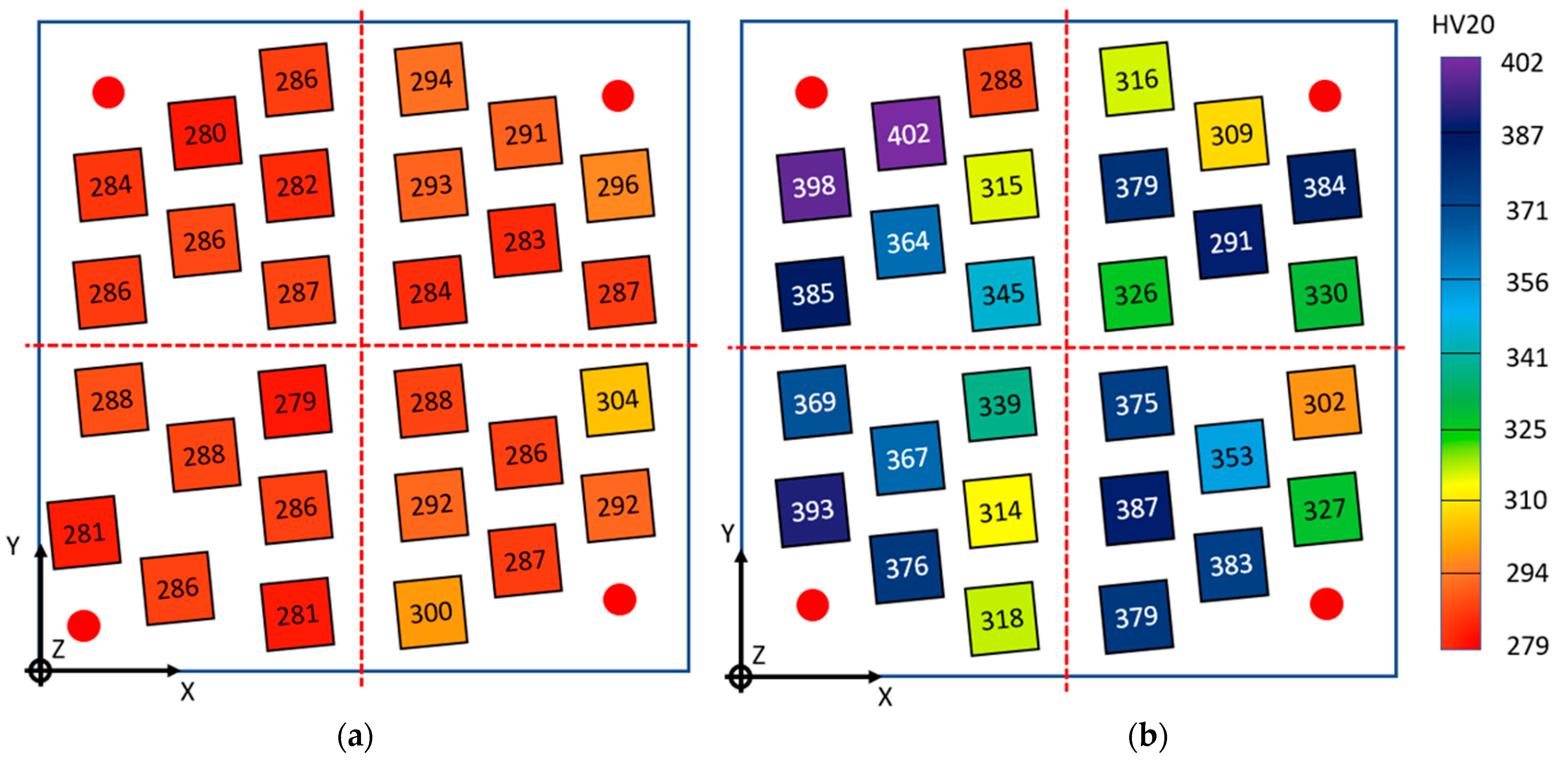
In Figure 10 and in Table 8, the hardness data of the whole set of specimens as built (that is to say, before the heat treatment) are reported for both the XY and YZ/XZ planes. The values represent the average of the five measures evaluated on every specimen for the XY surface and the perpendicular ones (XZ/XY planes). The average measurements are reported related to the position on the platform, and a colored palette is applied.
In the XY plane, the average measured hardness ranges from HV20 = 279 (specimens C3) to HV20 = 304 (specimen D1). In the vertical direction (XZ or YZ plane), the measured average hardness range is larger and ranges from HV20 = 288 (specimen A7) to HV20 = 402 (specimen A5).
The specimens can be defined as isotropic if the hardness value measured on one surface is included in the standard deviation range of the other. Only the specimens A7 (HV20 = 286~288), B2 (HV20 = 283~291), and D1 (HV20 = 304~302) can be considered isotropic. No one specimen of the quadrant C can be considered isotropic.
Specimens having the same process parameters (that is, named with the same number but different letter, according to Table 6 and Figure 2) are compared to check for hardness repeatability. Comparable hardness is found for specimens: A2 and C2 (only in the XY plane); A3 and C3; A4, B4, and C4; C5 and D5; A6 and C6; B7 and C7.
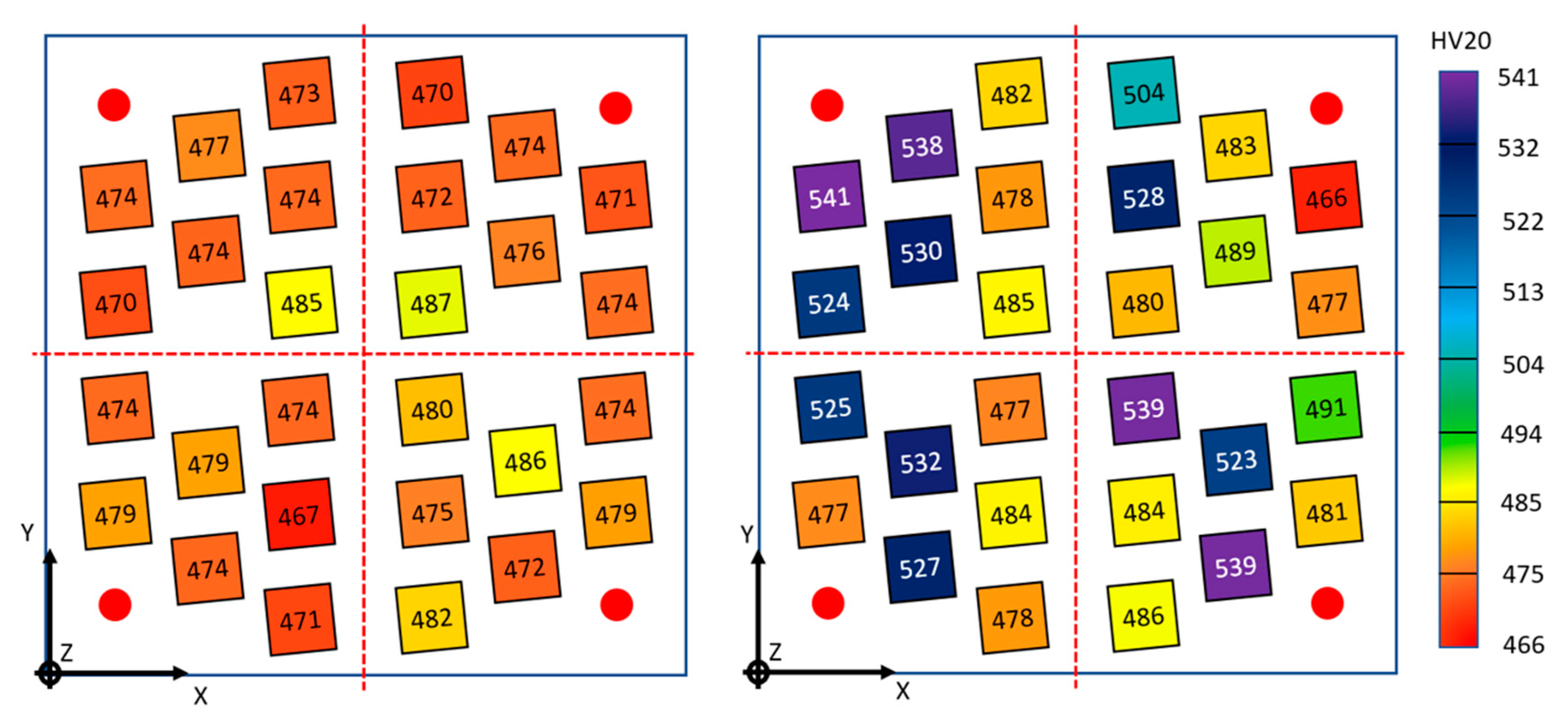
In Figure 11 and in Table 9 the corresponding results are reported for the heat-treated specimens. Heat-treated specimen hardness HV20 is generally more elevated than as-built specimens.
In the XY plane, the average measured hardness ranges from HV20 = 467 (specimen C6) to HV20 = 487 (specimen B3). Similarly, to the as-built specimens, the heat-treated specimens have similar hardness in the XY plane, regardless of the process parameters and quadrant, while the hardness in the XZ or YZ plane is noticeably scattered, as it ranges from HV20 = 481 (specimen D4) to HV20 = 541 (specimen A4).
The influence of heat treatment on the material isotropy on the build platform is more evident: 15 specimens (A7, A6, A3; B1, B2, B3, B4, B5; C3, C4, C7; D1, D4, D6, D7) can be considered isotropic and all the quadrants have at least three isotropic samples.
Specimens having the same process parameters (that is, named with the same number but different letter, according to Table 6 and Figure 3) are compared in order to check for hardness repeatability. Comparable hardness is found for specimens: A1 and C1; A2 and C2; A3, B3, and C3; C4 and D4; A5, C5 and D5; A6, C6, and D6; A7, C7, and D7.

4.4. Micrography Results

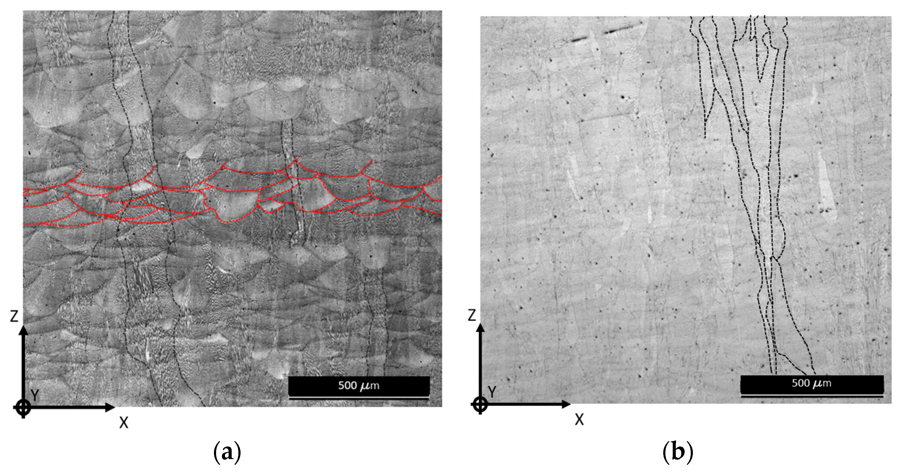
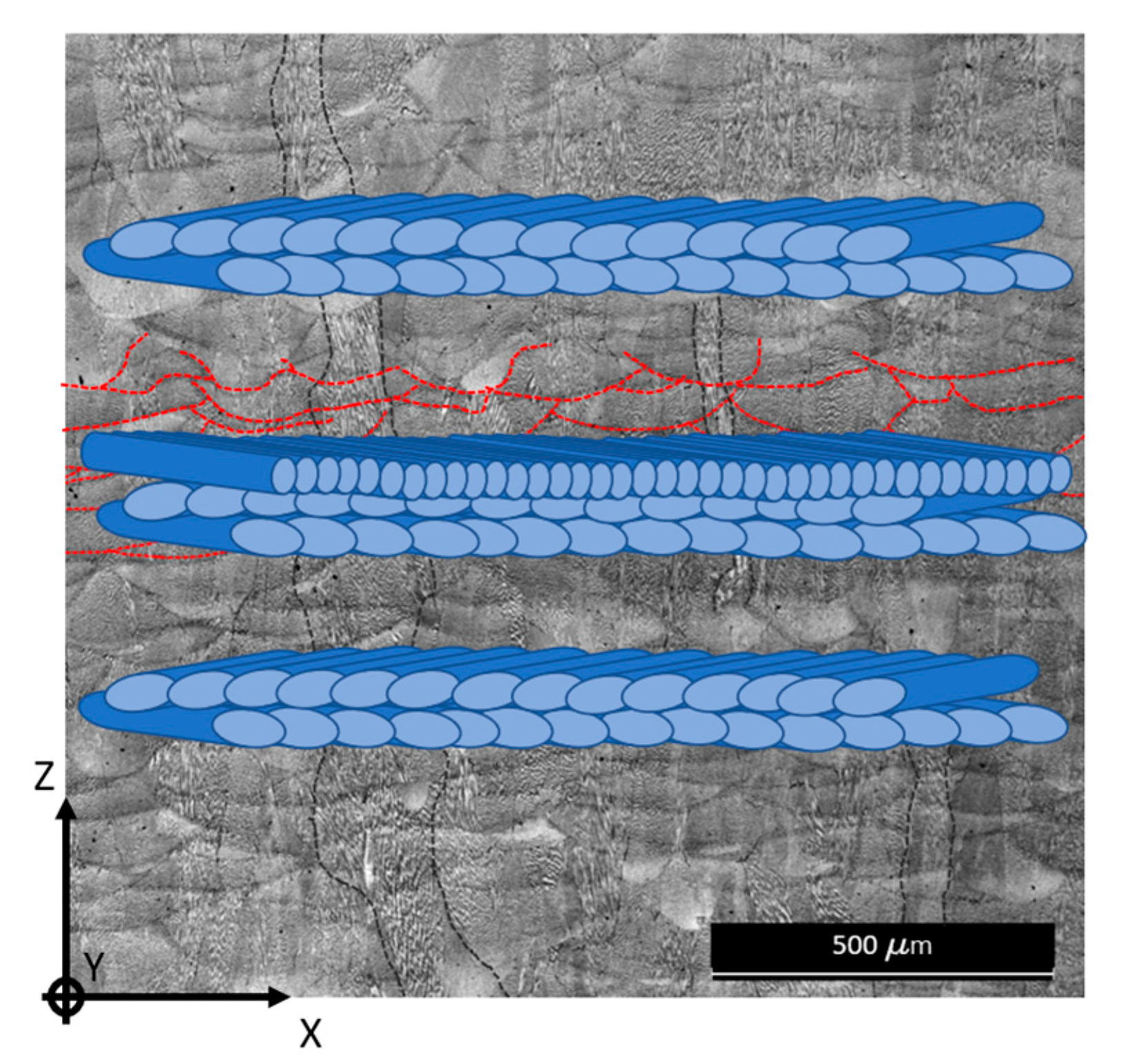
The microstructures of the LPBF B2 as-built and heat-treated specimens are shown in Figure 12 and Figure 13. XZ/YZ plane and XY plane differences can be clearly identified. Furthermore, as expected, the heat treatment plays a critical role in the microstructural arrangement of the material [53,54,55].
The as-built XZ/YZ image (Figure 12a) shows melting pools stratification and columnar grains with a main growing direction parallel to the Z building direction. This is due to the process thermal gradient from the bottom of the specimen to the end top surface [56]. After heat treatment (Figure 12b), the melting pools vanish and columnar grains, parallel to the building direction, constitute most of the microstructural arrangement. The as-built XY image (Figure 13a) shows remarkable laser tracks, which become less relevant after the heat treatment (Figure 13b), proving that a structural rearrangement occurs also on the XY plane, perpendicular to the building direction.
According to [57], the strength and hardness in an AM steel depend on the fineness of the solidification structure and on their chemical composition. All literature agrees in observing higher hardness in the presence of refined dendritic columns; the after treatment refined microstructure confirms the higher hardness measurements obtained in heat-treated specimens, and the lower hardness measurement is obtained in the XY plane rather than in the XZ/YZ plane for both as-built and heat-treated specimens.

5. Discussion

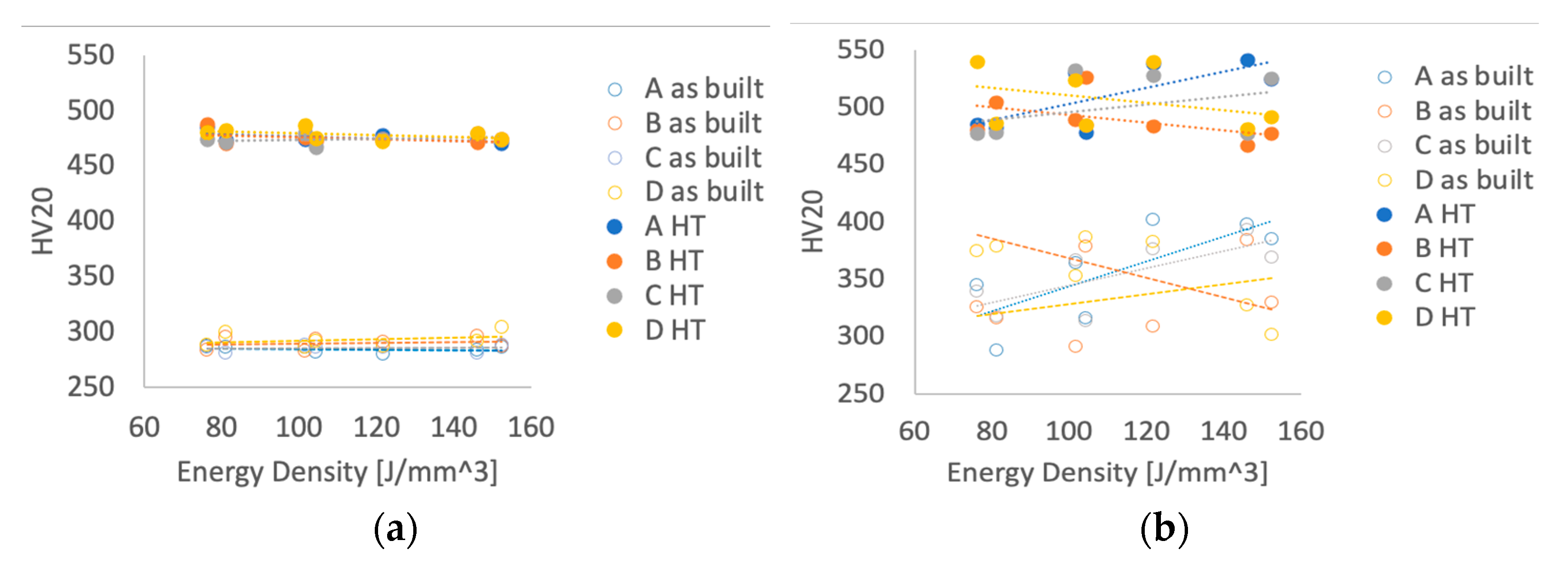
In Figure 14 the values of HV20 vs. energy density ED of the as-built and heat-treated specimens for the different quadrants (letters A, B, C, and D) and for the different planes are reported for XY and XZ/YZ measurements. Figure 14 reports the data presented in Figure 10 and Figure 11 and in Table 8 and Table 9 highlighting the hardness measure vs. the energy density. This plot points out how the energy density seems to not affect the scattering of the hardness measurements on the XZ/YZ plane in respect to the XY plane. It shows that the variation of energy density cannot be observed by hardness measurements performed on the XY deposition plane, while in the XZ/YZ perpendicular planes, the measurements are scattered and do not show a repeatable trend for the different set of data. This evidence is confirmed by the fact that the data measured in the four quadrants of the printing platform show different trends.
The different hardness behavior respect to the increasing of the energy density in the two planes can be explained as follows.
In the XY plane (that is, parallel to the printing platform), the hatch distance (0.105 mm) and the overlapping factor (0.7) are constant for all specimens (see Table 6). The DOE energy density variation is obtained by modifying the power and the scanning speed of the laser, not by changing the hatch distance. The indentation on this surface is perpendicular to melting pools, which are oriented in the same way with respect to indentation direction on the whole plane. This means that the deformation behavior of all measured points in this plane is similar and the hardness variation, in respect to the energy density, is small. This observation can also explain why the HV20 hardness shows the lowest scattering and the corresponding load was selected to indent a maximum number of layers equal to 2. It is possible to state that the XY plane hardness is not affected by the modification of power and scanning speed. A similar result is presented in [29].
In the XZ/YZ planes, perpendicular to the printing platform, due to scanning strategy, the indentation direction can be perpendicular, parallel, or in any way angled with respect to the laser moving direction (Figure 15). This means that when the instrument indents the surface, it can deform volumes of material with a different level of homogeneity, due to the presence of melting pool boundaries, which can be more or less dense in the direction of the indentation. The ZX/ZY plane indentation, perpendicular to the plane represented in Figure 15, deforms an area that can involve a laser track, especially if the indentation site is located in a segment where there is a high angled scanning strategy. This can cause a hardness of higher sensitivity with respect to a different value of energy density. According to this observation, the phenomena (ISE and RISE) observed in Section 4.1 and in Figure 8 can be explained.
Future research will include the position of the specimens on the printing platform in the process parameters in DOE planning.
The literature reports that for the AM material, differently from the tensile [56], fatigue crack growth [58], and low cycle fatigue [56] properties, the hardness is isotropic [37,39,41]. This is not so in our case, as the hardness changes significantly depending on which plane it is measured on. However, it is worth noticing that the minimum values of the scattered data of the XZ/YZ plane are comparable with the hardness in the XY plane. Hence, the hardness data in the XY plane can be considered a conservative value for the whole specimens. Moreover, also considering Figure 10a, it is possible to state that the hardness data in the XY plane do not change appreciably whether the specimens are positioned on the building platform. As already said, this is not the case of the hardness in the XZ/YZ plane (Figure 10b). In particular, poor repeatability is also noticed for the specimens positioned at the center of the building platform and having the same process parameters (i.e., specimens A3, B3, C3, D3). There, the laser beam acts more perpendicularly and thus, at least in theory, the coded process parameters should be more consistent to the real ones.
In the same Figure 14, with respect to the as-built specimens, the heat-treated specimens present a general higher hardness value in both the XY and XZ/YZ planes. This is a common properties transformation for InconelTM 718 post heat treatment [46,47]. The maximum value of hardness for as-built specimens is HV20 = 304 and HV20 = 402, respectively, for the XY plane and the XZ/YZ plane. For the heat-treated specimens, these values are HV20 = 487 and HV20 = 541, respectively. Moreover, the heat treatment increased the isotropy of the hardness. The hardness difference between the XY and the XZ/YZ planes is HV20 = 99 for the as-built specimens and HV20 = 54 for the heat-treated specimens. Undoubtedly, the increased anisotropy is a further positive effect of the heat treatment. Heat treatment also attenuate the dispersion of the hardness in the XZ/YZ plane. The percentage variation between the maximum and the minimum value of the as-built specimens, with respect to the minimum value, is 40% before the heat treatment and reduces to 16% after it.

6. Conclusions

In the present paper an experimental analysis is presented investigating the effects of AM process parameters on the hardness properties on InconelTM 718. The analysis is extended comparing as-built and heat-treated specimens.
A preliminary experimental investigation pointed out that, for the investigated range of printing parameter variation, the HV20 procedure for hardness measurement is the one that results in smaller scattering.
For as-built specimens, it results that the energy density modifies hardness properties of InconelTM 718 with a remarkable effect to the XZ/YZ plane and a negligible effect on the XY plane. The orientation of the printing direction with respect to indentation direction can be responsible of hardness scattering phenomena. This hypothesis can justify the HV20 lower scattering of data.
Most of the as-built specimens show a strong anisotropy for in-plane and growth directions. As-built specimens present a general increase of hardness with respect to increasing energy density. Heat-treated specimens present a general higher hardness value with respect to as-built specimens, according to literature.
A better homogeneity of hardness is evident in heat-treated specimens, thus pointing out that, to achieve a better isotopy behavior, it is necessary to introduce a strong microstructure modification via a heat treatment. In addition, to a better isotropy behavior, the heat treatment process introduces measurement repeatability. The difference between hardness value respect to the energy density is drastically reduced by the heat treatment.
In the present work, the influence on hardness of the distance from the center of the platform was not considered. In the considered DOE, for each platform quadrant, specimens with different distance from the center were obtained with different energy density. In addition, the influence of building height on hardness was not investigated. In the literature this influence is considered for as-built larger height specimens and heat treatment tends to reduce this influence. Lastly, the measuring procedure was according to a standard defined for bulk materials, as no standards are available for AM materials.
Future development of the present research will be dedicated to analyzing the indentation size effect (ISE) on the same DOE. Dedicated DOEs will be designed for investigating the influence of the distance from the center of the platform and of the printing height. Other materials and alloys are also under scouting.
Author Contributions

Conceptualization, M.C. and M.P.; methodology, M.P., M.C. and R.S.; validation, L.L. and M.C.; formal analysis, C.D. and R.S.; investigation, M.C. and L.L.; resources, D.B. and A.C.; data curation, R.S. and M.C.; writing—original draft preparation, M.C.; writing—review and editing, R.S., C.D. and M.P.; supervision, C.D. and R.S. All authors have read and agreed to the published version of the manuscript.

Funding

This research received no external funding.

Data Availability Statement

Data will be provided on demand.

Acknowledgments

The authors gratefully thank ASI (Italian Space Agency) for financial support of PhD research activity which lead to the present results.

Conflicts of Interest

The authors declare no conflict of interest.

References

  1. Zhang, X.; Tiwari, R.; Shooshtari, A.H.; Ohadi, M.M. An additively manufactured metallic manifold-microchannel heat exchanger for high temperature applications. Appl. Therm. Eng. 2018, 143, 899–908. [Google Scholar] [CrossRef]
  2. Blakey-Milner, B.; Gradl, P.; Snedden, G.; Brooks, M.; Pitot, J.; Lopez, E.; Leary, M.; Berto, F.; du Plessis, A. Metal additive manufacturing in aerospace: A review. Mater. Des. 2021, 209, 110008. [Google Scholar] [CrossRef]
  3. Kok, Y.; Tan, X.P.; Wang, P.; Nai, M.L.S.; Loh, N.H.; Liu, E.; Tor, S.B. Anisotropy and heterogeneity of microstructure and mechanical properties in metal additive manufacturing: A critical review. Mater. Des. 2018, 139, 565–586. [Google Scholar] [CrossRef]
  4. Gradl, P.; Greene, E.; Oritz, B.; Buzzell, J.; Garcia, C.; Wood, J.; Cooper, K. Additive Manufacturing of liquid rocket engine combustion devices: A summary of process developments and hot-fire testing results. In Proceedings of the 54th AIAA/SAE/ASEE Joint Propulsion Conference, Cincinnati, OH, USA, 9–11 July 2018. [Google Scholar]
  5. Soller, S.; Behr, R.; Beyer, S.; Laithier, F.; Lehmann, M.; Preuss, A.; Salapete, R. Design and Testing of Liquid Propellant Injectors for Additive Manufacturing. In Proceedings of the 7th European Conference for Aerospace Sciences (EUCASS 2017), Milano, Italy, 3–6 July 2017. [Google Scholar]
  6. Liuzzi, D.; Boffa, C.; Rudnykh, M.; Drigo, D.; Arione, L.; Ierardo, N.; Sirbi, A. Development of an Alm Thrust Chamber for Vega-E M10 Rocket Engine. Space Propuls. 2021, 2020+1, 1–8. [Google Scholar]
  7. Balbaa, M.; Mekhiel, S.; Elbestawi, M.; McIsaac, J. On selective laser melting of Inconel 718: Densification, surface roughness, and residual stresses. Mater. Des. 2020, 193, 108818. [Google Scholar] [CrossRef]
  8. Moussaoui, K.; Rubio, W.; Mousseigne, M.; Sultan, T.; Rezai, F. Effects of Selective Laser Melting additive manufacturing parameters of Inconel 718 on porosity, microstructure and mechanical properties. Mater. Sci. Eng. A 2018, 735, 182–190. [Google Scholar] [CrossRef]
  9. Li, Y.; Založnik, M.; Zollinger, J.; Dembinski, L.; Mathieu, A. Effects of the powder, laser parameters and surface conditions on the molten pool formation in the selective laser melting of IN718. J. Mater. Process. Technol. 2021, 289, 116930. [Google Scholar] [CrossRef]
  10. Fayazfar, H.; Salarian, M.; Rogalsky, A.; Sarker, D.; Russo, P.; Paserin, V.; Toyserkani, E. A critical review of powder-based additive manufacturing of ferrous alloys: Process parameters, microstructure and mechanical properties. Mater. Des. 2018, 144, 98–128. [Google Scholar] [CrossRef]
  11. Smith, W.; Hasemi, J. Foundations of Materials Science and Engineering, 6th ed.; McGraw Hill: New York, NY, USA, 2018; Volume 1. [Google Scholar]
  12. Callister, W.D., Jr.; Rethwish, D.G. Fundamentals of Materials Science and Engineering: An Integrated Approach, 5th ed.; Wiley: New York, NY, USA, 2018; Volume 1. [Google Scholar]
  13. Richard, R.G.; Budynas, G.; Nisbett, J.K.; Shigley, J.E. Shigley’s Mechanical Engineering Design; McGraw-Hill: New York, NY, USA, 2011. [Google Scholar]
  14. Pavlina, E.J.; van Tyne, C.J. Correlation of Yield Strength and Tensile Strength with Hardness for Steels. J. Mater. Eng. Perform. 2008, 17, 888–893. [Google Scholar] [CrossRef]
  15. Low, S.; Hattori, K.; Germak, A.; Knott, A. Proposed definition for the Brinell hardness indentation edge. In Proceedings of the 20th IMEKO World Congress, Busan, Republic of Korea, 9–14 September 2014; Volume 3, pp. 3–8. [Google Scholar] [CrossRef]
  16. BS EN ISO 6507-1; 2018 BSI Standards Publication Metallic Materials—Vickers Hardness Test. The BSI Standards Limited: London, UK, 2018.
  17. Slotwinskic, J.; Moylan, S. Applicability of existing materials testing standards for additive manufacturing materials. Addit. Manuf. Mater. Stand. Test. Appl. 2015, 49–66. [Google Scholar] [CrossRef]
  18. Keist, J.S.; Palmer, T.A. Development of strength-hardness relationships in additively manufactured titanium alloys. Mater. Sci. Eng. A 2017, 693, 214–224. [Google Scholar] [CrossRef]
  19. Revankar, G. ASM Handbook Volume 8: Mechanical Testing and Evaluation; ASM International: Almere, The Netherlands, 2000; Volume 8. [Google Scholar] [CrossRef]
  20. Dieter, G. Mechanical Metallurgy; Mc Graw-Hill Book Company: New York, NY, USA, 1961. [Google Scholar]
  21. BS EN ISO 6508-1; 2016 BSI Standards Publication Metallic Materials-Rockwell Hardness Test. The BSI Standards Limited: London, UK, 2016.
  22. BS EN ISO 6506-1; 2018 BSI Standards Publication Metallic Materials-Brinnel Hardness Test. The BSI Standards Limited: London, UK, 2018.
  23. Krishna, S.C.; Gangwar, N.; Jha, A.; Pant, B. On the Prediction of Strength from Hardness for Copper Alloys. J. Mater. 2013, 2013, 1–6. [Google Scholar] [CrossRef]
  24. Cahoon, J.R.; Broughton, W.; Kutzak, A.R. The Determination of Yield Strength From Hardness Measurements. Metall. Trans. 1971, 2, 1979–1983. [Google Scholar] [CrossRef]
  25. Zhang, P.; Li, S.; Zhang, Z.F. General relationship between strength and hardness. Mater. Sci. Eng. A 2011, 529, 62–73. [Google Scholar] [CrossRef]
  26. Tonelli, L.; Fortunato, A.; Ceschini, L. CoCr alloy processed by Selective Laser Melting (SLM): Effect of Laser Energy Density on microstructure, surface morphology, and hardness. J. Manuf. Process. 2020, 52, 106–119. [Google Scholar] [CrossRef]
  27. DebRoy, T.; Wei, H.L.; Zuback, J.S.; Mukherjee, T.; Elmer, J.W.; Milewski, J.O.; Beese, A.M.; Wilson-Heid, A.; De, A.; Zhang, W. Additive manufacturing of metallic components—Process, structure and properties. Prog. Mater. Sci. 2018, 92, 112–224. [Google Scholar] [CrossRef]
  28. Herzog, D.; Seyda, V.; Wycisk, E.; Emmelmann, C. Additive manufacturing of metals. Acta Mater. 2016, 117, 371–392. [Google Scholar] [CrossRef]
  29. Caiazzo, F.; Alfieri, V.; Casalino, G. On the Relevance of volumetric energy density in the investigation of inconel 718 laser powder bed fusion. Materials 2020, 13, 538. [Google Scholar] [CrossRef]
  30. BS EN ISO 6892-1; 2019 British Standards Institution, Metallic materials. Tensile testing. Part 1, Method of Test at Room Temperature. The BSI Standards Limited: London, UK, 2019.
  31. Salmi, A.; Calignano, F.; Galati, M.; Atzeni, E. An integrated design methodology for components produced by laser powder bed fusion (L-PBF) process. Virtual Phys. Prototyp. 2018, 13, 191–202. [Google Scholar] [CrossRef]
  32. Kruth, J.P.; Froyen, L.; van Vaerenbergh, J.; Mercelis, P.; Rombouts, M.; Lauwers, B. Selective laser melting of iron-based powder. J. Mater. Process. Technol. 2004, 149, 616–622. [Google Scholar] [CrossRef]
  33. Hauser, C.; Childs, T.H.C.; Taylor, C.M.; Badrossamay, M.; Akhtar, S.; Wright, C.S.; Youseffi, M.; Xie, J.; Fox, P.; O’Neill, W. Direct Selective Laser Sintering of Tool Steel Powders to High Density. Part A: Effects of Laser Beam Width and Scan Strategy. In Proceedings of the 2003 International Solid Freeform Fabrication Symposium, Austin, CA, USA, 4–6 August 2003. [Google Scholar] [CrossRef]
  34. Harrison, N.J.; Todd, I.; Mumtaz, K. Reduction of micro-cracking in nickel superalloys processed by Selective Laser Melting: A fundamental alloy design approach. Acta Mater. 2015, 94, 59–68. [Google Scholar] [CrossRef]
  35. Lu, Y.; Wu, S.; Gan, Y.; Huang, T.; Yang, C.; Junjie, L.; Lin, J. Study on the microstructure, mechanical property and residual stress of SLM Inconel-718 alloy manufactured by differing island scanning strategy. Opt. Laser Technol. 2015, 75, 197–206. [Google Scholar] [CrossRef]
  36. Dehoff, R.R.; Kirka, M.M.; Sames, W.J.; Bilheux, H.; Tremsin, A.S.; Lowe, L.E.; Babu, S.S. Site specific control of crystallographic grain orientation through electron beam additive manufacturing. Mater. Sci. Technol. 2015, 31, 931–938. [Google Scholar] [CrossRef]
  37. Zhao, Y.; Li, K.; Gargani, M.; Xiong, W. A comparative analysis of Inconel 718 made by additive manufacturing and suction casting: Microstructure evolution in homogenization. Addit. Manuf. 2020, 36, 101404. [Google Scholar] [CrossRef]
  38. BS EN ISO 6507-4 ; 2018 BSI Standards Publication Metallic Materials—Vickers Hardness Test. The BSI Standards Limited: London, UK, 2018.
  39. Tian, Y.; McAllister, D.; Colijn, H.; Mills, M.; Farson, D.; Nordin, M.; Babu, S. Rationalization of microstructure heterogeneity in INCONEL 718 builds made by the direct laser additive manufacturing process. Met. Mater. Trans. A Phys. Met. Mater. Sci. 2014, 45, 4470–4483. [Google Scholar] [CrossRef]
  40. Stevens, E.L.; Toman, J.; To, A.; Chmielus, M. Variation of hardness, microstructure, and Laves phase distribution in direct laser deposited alloy 718 cuboids. Mater. Des. 2017, 119, 188–198. [Google Scholar] [CrossRef]
  41. Hosseini, E.; Popovich, V.A. A review of mechanical properties of additively manufactured Inconel 718. Addit. Manuf. 2019, 30, 100877. [Google Scholar] [CrossRef]
  42. Datsko, J.; Hartwig, L.; Mcclory, B. On the Tensile Strength and Hardness Relation for Metals. ASM Int. 2001, 10, 718–722. [Google Scholar] [CrossRef]
  43. Jiang, R.; Mostafaei, A.; Wu, Z.; Choi, A.; Guan, P.-W.; Chmielus, M.; Rollett, A.D. Effect of heat treatment on microstructural evolution and hardness homogeneity in laser powder bed fusion of alloy 718. Addit. Manuf. 2020, 35, 101282. [Google Scholar] [CrossRef]
  44. Liu, X.; Wang, K.; Hu, P.; He, X.; Yan, B.; Zhao, X. Formability, microstructure and properties of inconel 718 superalloy fabricated by selective laser melting additive manufacture technology. Materials 2021, 14, 991. [Google Scholar] [CrossRef]
  45. Deng, D.; Lin, R.; Brodin, H.; Moverare, J. Microstructure and mechanical properties of Inconel 718 produced by selective laser melting: Sample orientation dependence and effects of post heat treatments Materials Science & Engineering A Microstructure and mechanical properties of Inconel 718 produ. Mater. Sci. Eng. A 2018, 713, 294–306. [Google Scholar] [CrossRef]
  46. Amato, K.N.; Gaytan, S.M.; Murr, L.E.; Martinez, E.; Shindo, P.W.; Hernadez, J.; Colins, S.; Medina, F. Microstructures and mechanical behavior of Inconel 718 fabricated by selective laser melting. Acta Mater. 2012, 60, 2229–2239. [Google Scholar] [CrossRef]
  47. Wang, H.; Dhiman, A.; Ostergaard, H.E.; Zhang, Y.; Siegmund, T.; Kruzic, J.J.; Tomar, V. Nanoindentation based properties of Inconel 718 at elevated temperatures: A comparison of conventional versus additively manufactured samples. Int. J. Plast. 2019, 120, 380–394. [Google Scholar] [CrossRef]
  48. Pleass, C.; Jothi, S. Influence of powder characteristics and additive manufacturing process parameters on the microstructure and mechanical behaviour of Inconel 625 fabricated by Selective Laser Melting. Addit. Manuf. 2018, 24, 419–431. [Google Scholar] [CrossRef]
  49. Kampouris, A.K.; Konstantinidis, A.A. On the interpretation of the indentation size effect (ISE) through gradient theory for Vickers and Berkovich indenters. J. Mech. Behav. Mater. 2017, 25, 161–164. [Google Scholar] [CrossRef]
  50. Tucho, W.M.; Cuvillier, P.; Sjolyst-Kverneland, A.; Hansen, V. Microstructure and hardness studies of Inconel 718 manufactured by selective laser melting before and after solution heat treatment. Mater. Sci. Eng. A 2017, 689, 220–232. [Google Scholar] [CrossRef]
  51. Durst, K.; Backes, B.; Göken, M. Indentation size effect in metallic materials: Correcting for the size of the plastic zone. Scr. Mater. 2005, 52, 1093–1097. [Google Scholar] [CrossRef]
  52. Kathavate, V.S.; Kumar, B.P.; Singh, I.; Prasad, K.E. Analysis of indentation size effect (ISE) in nanoindentation hardness in polycrystalline PMN-PT piezoceramics with different domain configurations. Ceram. Int. 2021, 47, 11870–11877. [Google Scholar] [CrossRef]
  53. Ghorbanpour, S.; Deshmukh, K.; Sahu, S.; Riemslag, T.; Reinton, E.; Borisov, E.; Popovich, A.; Bertolo, V.; Jiang, Q.; Sanchez, M.T.; et al. Additive manufacturing of functionally graded inconel 718: Effect of heat treatment and building orientation on microstructure and fatigue behaviour. J. Mater. Process. Tech. 2022, 306, 117573. [Google Scholar] [CrossRef]
  54. Tillmann, W.; Schaak, C.; Nellesen, J.; Schaper, M.; Aydinöz, M.; Hoyer, K.P. Hot isostatic pressing of IN718 components manufactured by selective laser melting. Addit. Manuf. 2017, 13, 93–102. [Google Scholar] [CrossRef]
  55. Ni, M.; Chen, C.; Wang, X.; Wang, X.; Li, R.; Zhang, X.; Zhou, K. Anisotropic tensile behavior of in situ precipitation strengthened Inconel 718 fabricated by additive manufacturing. Mater. Sci. Eng. A 2017, 701, 344–351. [Google Scholar] [CrossRef]
  56. Gribbin, S.; Bicknell, J.; Jorgensen, L.; Tsukrov, I.; Knezevic, M. Low cycle fatigue behavior of direct metal laser sintered Inconel alloy 718. Int. J. Fatigue 2016, 93, 156–167. [Google Scholar] [CrossRef]
  57. Strondl, A.; Palm, M.; Gnauk, J.; Frommeyer, G. Microstructure and mechanical properties of nickel based superalloy IN718 produced by rapid prototyping with electron beam melting (EBM). Mater. Sci. Technol. 2011, 27, 876–883. [Google Scholar] [CrossRef]
  58. Konečná, R.; Kunz, L.; Nicoletto, G.; Bača, A. Long fatigue crack growth in Inconel 718 produced by selective laser melting. Int. J. Fatigue 2016, 92, 499–506. [Google Scholar] [CrossRef]
Figure 1. ED parameters schematic representation.
Jmmp 07 00036 g001
Figure 2. SEM-EDS chemical composition analysis of InconelTM 718 powder.
Jmmp 07 00036 g002
Figure 3. Building platform and coordinate system.
Jmmp 07 00036 g003
Figure 4. Island scanning strategy schematic representation. The separation between islands is in red and the zig-zag directions are in blue.
Jmmp 07 00036 g004
Figure 5. Thermal treatment cycle.
Jmmp 07 00036 g005
Figure 6. Specimen layer and skin structure.
Jmmp 07 00036 g006
Figure 7. Measured surface and local specimen reference system.
Jmmp 07 00036 g007
Figure 8. Preliminary hardness testing results of the specimen A1.
Jmmp 07 00036 g008
Figure 9. Relative density vs. specimen number (a) and ED (b).
Jmmp 07 00036 g009
Figure 10. Color scale-based hardness representation for as-built specimens: XY plane (a) and XZ/YZ plane (b).
Jmmp 07 00036 g010
Figure 11. Color scale-based hardness representation for heat-treated specimens: XY plane (left) and XZ/YZ plane (right).
Jmmp 07 00036 g011
Figure 12. XZ/YZ planes as-built (a) and heat-treated (b) micrographic images. The red dotted lines highlight random examples of melting pools and the black dotted lines columnar grains parallel to the Z building direction.
Jmmp 07 00036 g012
Figure 13. XY plane as-built (a) and heat-treated (b) micrographic images.
Jmmp 07 00036 g013
Figure 14. Specimens’ hardness vs. energy density on XY plane (a) and on XZ/YZ plane (b) for as-built and heat-treated (HT) specimens.
Jmmp 07 00036 g014
Figure 15. A ZX/ZY plane scanning strategy representation.
Jmmp 07 00036 g015
Table 1. Powder chemical composition provided by Carpenter Additive powder supplier (%w).
CFeNOCuBCoAlTiNb + TaMoNiCrSPSiMn
0.03balance0.010.02<0.1<0.0010.10.531.014.923.1052.3018.90.010.0040.040.02
Table 2. Powder chemical composition obtained by EDS-SEM analysis (%w).
NiCrFeNbMoTiCuOTaBCoAlSPSiMn
54.617.9217.184.722.81.120,73 Balance
Table 3. Powder sieve analysis (%w) provided by Carpenter Additive powder supplier.
+63 μm+53 μm+45 μm
005.18
Table 4. Powder laser size diffraction (%w) provided by Carpenter Additive powder supplier.
Dv 10 (μm)Dv 90 (μm)Dv 50 (μm)−5 μm (%vol)−15 μm (%vol)
21.757.835.901
Table 5. Powder Hall flow and apparent density analysis provided by Carpenter Additive powder supplier.
Hall flowFRHs/50 g14
Apparent densityBulk densityg/cm34.12
Table 6. Main body and contour process parameters.
BodyLayer thickness (mm)0.03
Spot Size (mm)0.15
Hatch distance (mm)0.105
Overlap Factor (mm)0.7
ContourPower (W)192
Spot size (mm)0.15
Beam compensation (mm)0.075
Contour Speed (mm/s)1600
Hatch Zone Border (mm)0.065
Table 7. Body process parameters for different specimens.
Specimen NumberLaser Power (W)Scanning Speed (mm/s)Energy Density (J/mm3)
1192400152.38
2192600101.59
319280076.19
4230500146.03
5230600121.69
6230700104.31
723090081.13
Table 8. Hardness values for as-built specimens.
direction A1A2A3A4A5A6A7
XYaverage286.68286.56287.89284.17280.72282.04286.94
std dev4.656.583.216.385.814.928.5
Zaverage385.43364.96345.03398.44402.05315.83288.52
std dev2.325.243.7511.395.578.932.84
B1B2B3B4B5B6B7
XYaverage287.49283.11284.86296.24291.22293.11294.28
std dev3.64.863.468.078.12.787.19
Zaverage330.21291.59326.49384.59309.81379.72316.5
std dev4.195.114.974.816.536.065.51
C1C2C3C4C5C6C7
XYaverage288.46288.23279.86281.96286.92286.6281.55
std dev3.423.816.514.163.754.189.17
Zaverage369.78367.14339.9393.34376.48314.9318.83
std dev5.473.784.125.5610.5311.475.38
D1D2D3D4D5D6D7
XYaverage304.22286.8288.17292.82287.74292.47300.83
std dev11.285.022.235.456.073.662.96
Zaverage302.96353.62375.42327.23383.98387.36379.08
std dev4.045.115.982.324.841.5710.87
Table 9. The hardness values for heat-treated specimens.
direction A1A2A3A4A5A6A7
XYaverage470.25474.94477.77474.55477.88474.47473.86
std dev4.216.656.36.772.5410.515.4
Zaverage524.02530.26485.9541.34538.15478.77482.82
std dev3.656.518.773.6312.989.8410.42
B1B2B3B4B5B6B7
XYaverage474.46476.28487.9471.86474.21472.43470.25
std dev2.064.464.397.055.465.3910.52
Zaverage477.2489.82480.23466.87483.87528.35504.42
std dev4.558.498.129.599.815.432.87
C1C2C3C4C5C6C7
XYaverage474.44479.27474.2479.71474.95467.98471.13
std dev9.525.424.744.967.228.594.05
Zaverage525.29532.87477.46477.96527.8484.43478.82
std dev7.875.313.166.333.46.554.07
D1D2D3D4D5D6D7
XYaverage474.42486.04480.96479.13472.01475.26482.1
std dev7.933.158.95.654.768.218.16
Zaverage491.1523.71539.61481.04539.07484.63486.34
std dev4.5413.338.135.345.4811.843.8
Disclaimer/Publisher’s Note: The statements, opinions and data contained in all publications are solely those of the individual author(s) and contributor(s) and not of MDPI and/or the editor(s). MDPI and/or the editor(s) disclaim responsibility for any injury to people or property resulting from any ideas, methods, instructions or products referred to in the content.