Article

Residual Stresses in a High- and a Medium-Entropy Alloy due to TIG and Friction Stir Welding

1
Bundesanstalt für Materialforschung und-prüfung (BAM), Unter den Eichen 87, 12205 Berlin, Germany
2
Institute for Material Science and Joining Technology (IWF), Otto-von-Guericke University, Universitätsplatz 2, 39104 Magdeburg, Germany
*
Author to whom correspondence should be addressed.
J. Manuf. Mater. Process. 2022, 6(6), 147; https://doi.org/10.3390/jmmp6060147
Submission received: 5 October 2022 / Revised: 14 November 2022 / Accepted: 15 November 2022 / Published: 18 November 2022
(This article belongs to the Special Issue Frontiers in Friction Stir Welding and Processing)

Abstract

:
The new alloying concept of multi-element systems with defined entropy (HEA—high-entropy alloy; MEA—medium-entropy alloy) is gaining increasing importance in materials research. Significantly improved properties or combinations of properties are shown by some HEA/MEA systems. Thus, primarily the production and resulting microstructures of HEA, as well as its properties, have been investigated so far. Furthermore, processing is a main issue in transferring HEA systems from the laboratory to real components. Since welding is the most important joining process for metals, it is crucial to investigate the influence of welding to guarantee component integrity. Welding leads to residual stresses, which significantly affect the component integrity. Hence, the focus of this study is the residual stress formation and distribution in a CoCrFeMnNi HEA and ternary CoCrNi MEA using two different welding processes: tungsten inert gas (TIG) welding and solid-state friction stir welding (FSW). As a pathway for the application of HEA in this investigation, for the first time, residual stress analyses in realistic near-component specimens were performed. The residual stresses were determined by X-ray diffraction (XRD) on the surfaces of top and root weld side. The results were correlated with the local welding microstructures. The results show that both FSW and TIG generate significant tensile residual stresses on the weld surfaces in, and transverse to, the welding direction. In the case of FSW of the CoCrFeMnNi HEA, the longitudinal residual stresses are in the range of the yield strength of approx. 260 MPa in the weld zone.

1. Introduction

Since the first publications in 2004 [1], the interest of materials research in high- and medium-entropy alloys (HEAs and MEAs) as a single-phase class of the multi-principal element alloys (MPEAs) has been steadily increasing. These novel materials contain at least five (HEA) or three (MEA) alloying elements, with possible concentrations for each element between 5–35 at.%. and are defined as single-phase solid solutions. This distinguishes the HEA concept from conventional alloys with one or two main alloying elements, as in steel or aluminium alloys. These novel alloy concepts offer enormous potential for the substitution of conventional alloys due to excellent property combinations, e.g., to overcome the traditional trade-off between strength and ductility [2,3], or to achieve high strength combined with excellent corrosion resistance, even surpassing Ni alloys in high-temperature applications [4]. In the case of more than one phase, the term CCA (chemical complex alloys) has become established for these materials. To enable the use of HEAs as functional or structural materials in real components, economic and safe processability is important, in addition to the targeted special application properties.
The focus of this research study is, therefore, on welding as the primary joining method for metals. Currently (December 2021), there are approximately 100 publications published worldwide that include the terms “welding” and “HEA”. Possible HEA compositions have a wide range. Most scientific studies deal with 3D transition, light, and refractory metal HEA concepts [3]. The largest number of scientific papers are dedicated to the so-called “Cantor” alloy (Co20Cr20Fe20Mn20Ni20, named after the inventor Brian Cantor). Despite the number of alloying elements, the material has a single-phase face-centred cubic (fcc) microstructure. This quinary alloy (HEA), as well as the ternary alloy Co33.3Cr33.3Ni33.3 (MEA), shows excellent mechanical properties, e.g., under cryogenic conditions [5] and corresponding low-temperature components. Previous studies on the weldability of HEAs have increasingly focused on solid-state friction stir welding (FSW) [6,7], TIG [8], and electron beam and laser beam fusion welding [4,9]. Weldability as a material property (according to ISO/TR 581:2005 [10]) is the possibility to manufacture a component from a certain material by welding, providing it can fulfil the intended tasks over the service life under the given manufacturing conditions (technological process) and under consideration of the design. Against this background, previous investigations have shown qualitatively good weldability for CoCrFeMnNi HEAs. This is mainly because further process steps, such as preheating or post-weld heat treatment processes, can be dispensed with to obtain defect-free weld seams [4,11]. However, practical welding processing of these HEA and MEA types is still largely unexplored in terms of component-related specimen dimensions, since weld tests are generally performed on very small-scale specimens [4]. In contrast to arc welding, such as TIG (melting of substrate by welding arc column), during FSW, weld heat is generated by the friction of the rotating tool shoulder with the material to be welded. A significant advantage is the friction-related process temperature of 0.75–0.9 times the melting point Tm, which is below the melting temperature [12]. At these temperatures, the material is in a highly viscous state and is stirred in the fusion zone by means of a pin at the tool, cf., Figure 1b. This prevents the precipitation of intermetallic phases in the weld material (WM), and thus the tendency to brittle fracture. So-called welding imperfections, such as flaws in the weld or deviations from the intended geometry, are referred as “defects” in accordance with the FSW specifications in DIN EN ISO 6520-2 [13].
Regarding the formation of residual stresses in single-pass arc welds, it is a well-known fact that the highest tensile residual stresses in longitudinal direction are present in the centre of the weld seam. These are transformed into compressive residual stresses in the HAZ, and become equal to the residual stress state of the base material with increasing distance from the weld seam. The cause of residual stresses during arc welding of non-transformation materials is the inhomogeneous and design-related restrain during cooling after welding [14,15].
Basically, FSW welds for austenitic 304 L show high tensile residual stresses in the longitudinal direction, and these are only minimally increased in the transverse direction, in the weld zone in experiment [16] and numerical simulation [17] scenarios. These tensile residual stresses in the longitudinal direction decrease and may even change to compressive residual stresses with increasing distance to the weld centre. Singh et al. show that the tool geometry (e.g., shoulder diameter) has a large effect on the heat generation, and thus, also a significant influence on the residual stresses in Mg alloys [18].
This also includes the formation of welding residual stresses, which can only be investigated and quantified with a sufficient sample size. In welds, high welding residual stresses can have an adverse effect on the safety and performance of the welded component. Consequently, it is therefore necessary to determine these residual stresses using adequately high specimen dimensions as a function of the material and welding process applied. There have been no studies in the literature on this subject to date.

2. Materials and Methods

Based on previous work [8,19], TIG welding and FSW experiments were carried out using a CoCrFeMnNi HEA and a CoCrNi MEA in order to investigate their specific weldability. Table 1 shows the hardness (according to DIN EN ISO 6507-1 [20]) of both alloys and the chemical composition measured with an electron beam microprobe (ESMA, JEOL JXA-8900-RL, JEOL GmbH, Freisling Germany).
The production of both alloys was kindly carried out by the Ruhr-University Bochum (group of Prof. G. Laplanche) by melting pure elements (purity: 99.9 wt.%) with a vacuum induction furnace and homogenisation at 1200 °C for 48 h. The diameter of the ingots was reduced from 40 mm to 17 mm by rotary forging, followed by recrystallisation annealing at 1020 °C (HEA) or 1060 °C (MEA) for 60 min, cf., [21]. Afterwards, a single-phase fcc alloy with some minor production-related impurities was produced (Cr- and Mn-rich oxides). Detailed information on the appearing microstructure was presented elsewhere in [5,22]. The sample sheets (dimensions: 80 × 14 × 1 mm3) for the TIG welding and FSW tests were taken from the ingots by wire electrical discharge machining (EDM). The specimen surfaces were subsequently subjected to the cutting process, and ground to remove EDM process residues on the surface [8].
The TIG welding experiments were carried out using a specially designed and custom-manufactured specimen clamping system for the specimen dimensions, and to realize a degree of stiffness or restraint as it appears in real welded joints. The test setup is shown in Figure 1a. Here, in addition to the TIG torch, a gas trailing nozzle can be seen to cover the weld metal (WM) even after welding. The same applies to the root, which is to be protected from oxidation by means of shielding gas. A Polysoude PC 600 TIG system with the data provided in Table 2 was used (pulsed arc), ensuring a remelted bead-on-plate-like weld seam of approximately 70 mm in length. The FSW tests were carried out on a five-axis machining centre DMU 65 (DMG MORI), cf., Figure 1b. The movement of the tool was path-controlled. Figure 1b shows the test setup. The FSW tool (cf., Figure 1c) consisted of a sintered W-alloy with 1.5 wt.% La2O3. The tool shoulder (diameter: 8 mm) was concave. The tool pin was 0.9 mm long and tapered (diameter: 2.0–2.4 mm). In addition, three surfaces were machined on the pin to support the material transport. In the test, the tool was set at 2° against the feed direction. The plunge speed was 10 mm × min−1, the rotational speed was 3000 min−1, and the feed speed was 100 mm × min−1. The FSW parameters are summarized in Table 3. During the experiments, the temperature was measured directly at the shoulder edge of the tool with a ratio pyrometer (measuring range: 350–1300 °C). For the subsequent light microscopic examination, cross-sections of the weld seam were machined, ground, and finally polished with 1 µm diamond paste. The microstructure was etched using Adler’s etchant at room temperature for 1 min and Beraha-II etchant for 15 s at room temperature, respectively.
To determine the effect of welding processing, the residual stresses were analysed with X-ray diffraction (XRD) using a Stresstech Goniometer G3 and sin2ψ method, cf., Table 4. XRD was chosen due to its characterisation of near surface stresses. It was shown that the maximum tensile residual stresses and highest residual stress gradients are predominantly present at the surface of welded joints, and can therefore be detected by XRD. Current comparative investigations in sheet thickness direction, e.g., with neutron diffraction or the contour method on repair welds confirm this [23]. In addition, possible crack initiation is to be expected at surface defects. The nondestructive XRD method is more feasible compared to measurement techniques considering residual stresses in bulk, where large facilities are necessary, e.g., neutron diffraction. The well-established hole drilling method could not be applied due to the inferior thickness of the welded plates (1 mm) and the limitation of unreliable measurements for residual stresses greater than 60% of the yield strength, or Rp0.2. The calculations of the residual stresses were performed using the following elastic moduli that have already been reported in the literature for the CoCrFeMnNi HEA (Poisson’s ratio ϑ = 0.259; Young’s modulus E = 207 GPa) [24] and the CoCrNi MEA (ϑ = 0.31, E = 235 GPa) [25].

3. Results

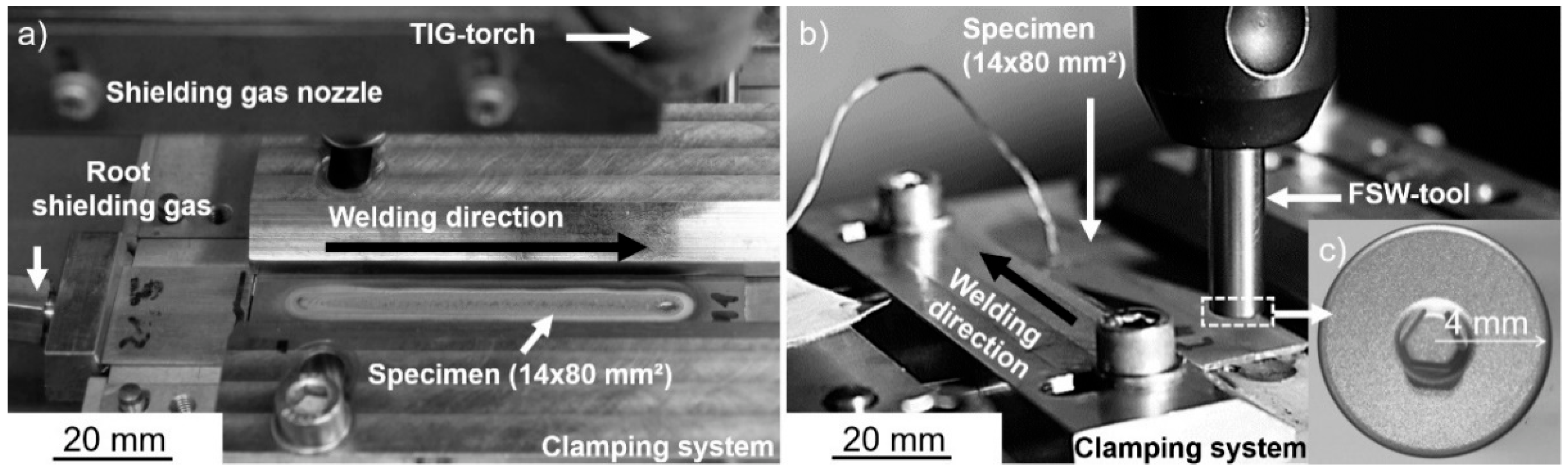
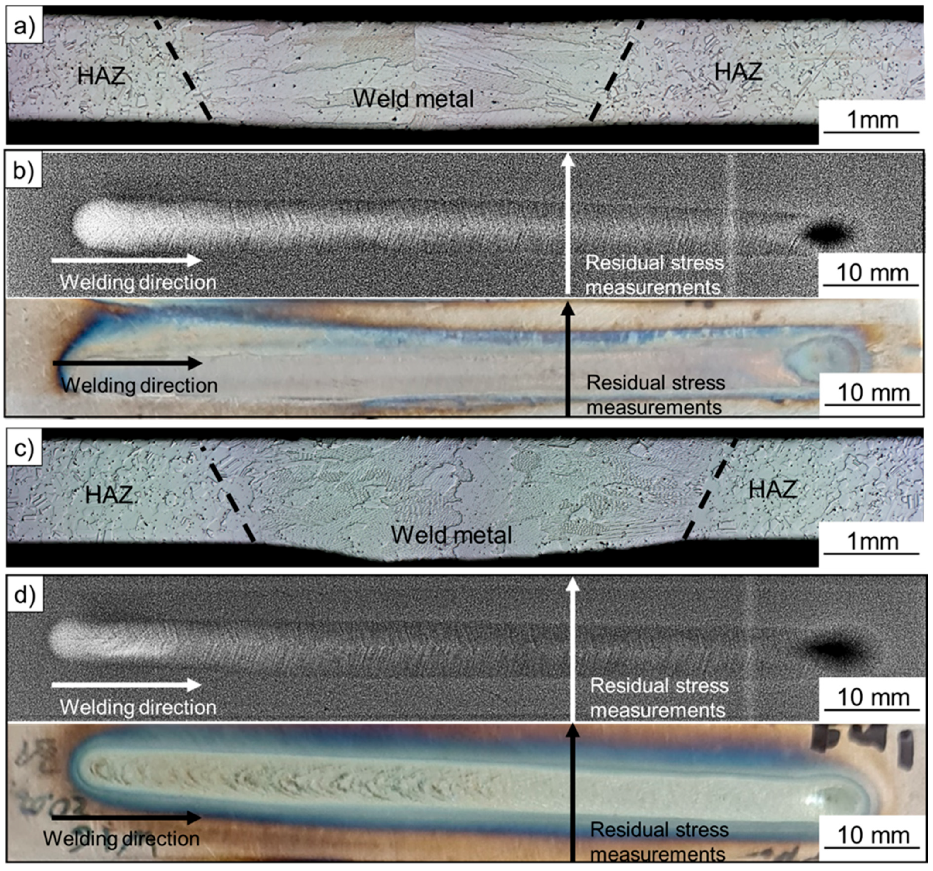
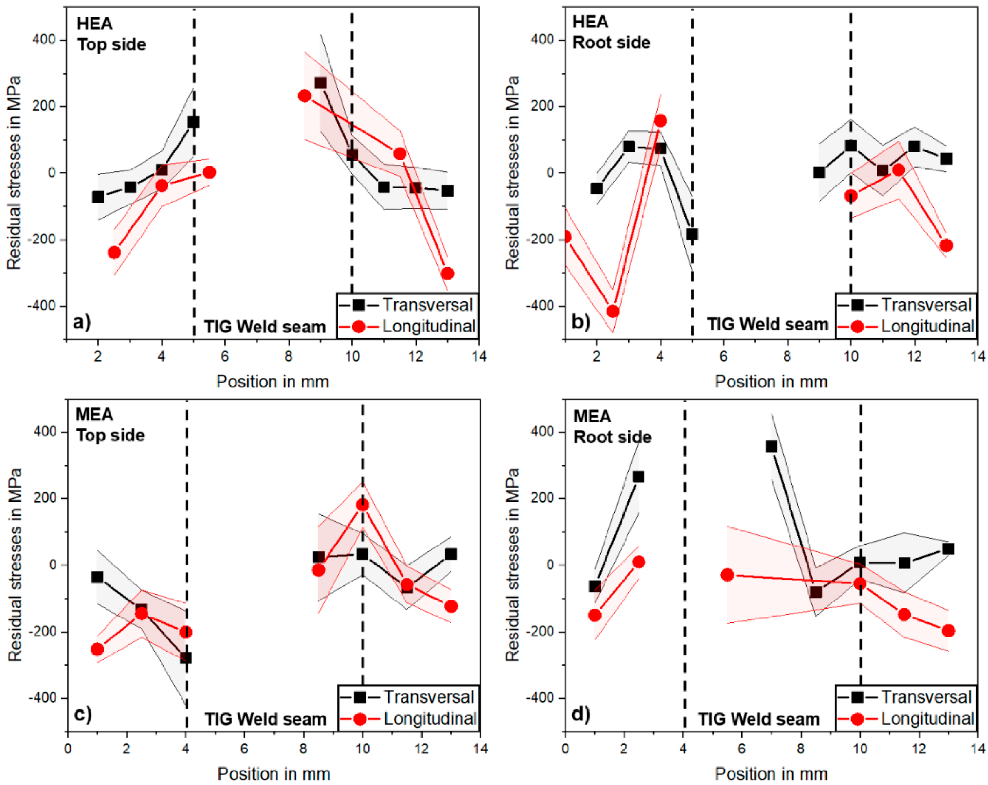
3.1. TIG Welding Experiments

Figure 2 shows the macros of the cross-section for the TIG welds of both alloys and the respective images of the X-ray radiographic inspection. Both welds exhibited no (unacceptable) imperfections (e.g., cracks). They showed full weld penetration for all welds, demonstrating that the welding parameters are suitable for this specific type of materials with 1 mm thickness. Dendritic solidification of the WM occurred, cf., Figure 2a,c, with large columnar grains. No considerable influence on the microstructure (growth of the recrystallized BM) was exhibited in the heat-affected zone (HAZ), i.e., the heat-influenced but non-melted region.
In Figure 3, the residual stress profiles of the welds at the top and root side of both alloys are shown. XRD analysis in the WM was, however, not always feasible, or led to very high deviations due to the columnar and large grains produced by the welding process for all specimen sides and alloys. For the HEA, the transverse residual stresses, cf., Figure 3a,b, were between −100 (i.e., compressive stresses) and 0 MPa on the top side of the BM, increasing in the HAZ and towards the WM to approx. +300 MPa (i.e., tensile stresses) being the Rp0.2 strength of the material (+273 MPa) [26]. On the root side, an almost mirrored behaviour was observed, with 0 to +100 MPa tensile residual stresses in the BM and decreasing residual stress values towards the WM down to approx. −200 MPa. This typically occurs because of restraint shrinkage and restraint angular distortion of the weld in connection with bending stresses. Hence, in the longitudinal direction at the top and root side of the weld, compressive stresses are dominating in the BM, which, according to commonly accepted residual stress models and concepts [14], occur in stable single-phase materials, such as austenitic steels, as a compensation for high tensile residual stresses in the WM due to shrinkage in the longitudinal direction of the weld, which is inhibited during cooling of the specimen. However, due to the large grain size of the WM, it was not possible to determine the residual stresses in these regions.
The MEA exhibited transverse residual stresses, cf., Figure 3c,d, between −100 MPa and 0 MPa on the top and root side of the BM, which increased in the HAZ towards the WM at the root side to approx. +300 MPa, this being the Rp0.2 strength of the material. On the top side, decreasing residual stress values towards the WM down to approx. −300 MPa was observed. It is assumed that this reversed behaviour of the MEA compared to the HEA welds can be attributed to a slightly deviating shrinkage behaviour. This may be caused by a larger weld zone width, for instance, and thus, to an impeded negative angular distortion of the weld specimen. The resulting bending stresses then led to higher tensile residual stresses in the weld area on the root side than in the top side area. The longitudinal residual stresses exhibited compressive values down to approx. −250 MPa in the BM, increasing to tensile stresses in the HAZ. Thus, a very similar behaviour as observed and discussed for the HEA welds can be stated.
The results show a behaviour to be expected for austenitic materials, which do not show a crystal lattice transformation [14,15]. The highest tensile residual stresses were measured in the weld and decreased with distance from the weld centre, and changed to compressive residual stresses.

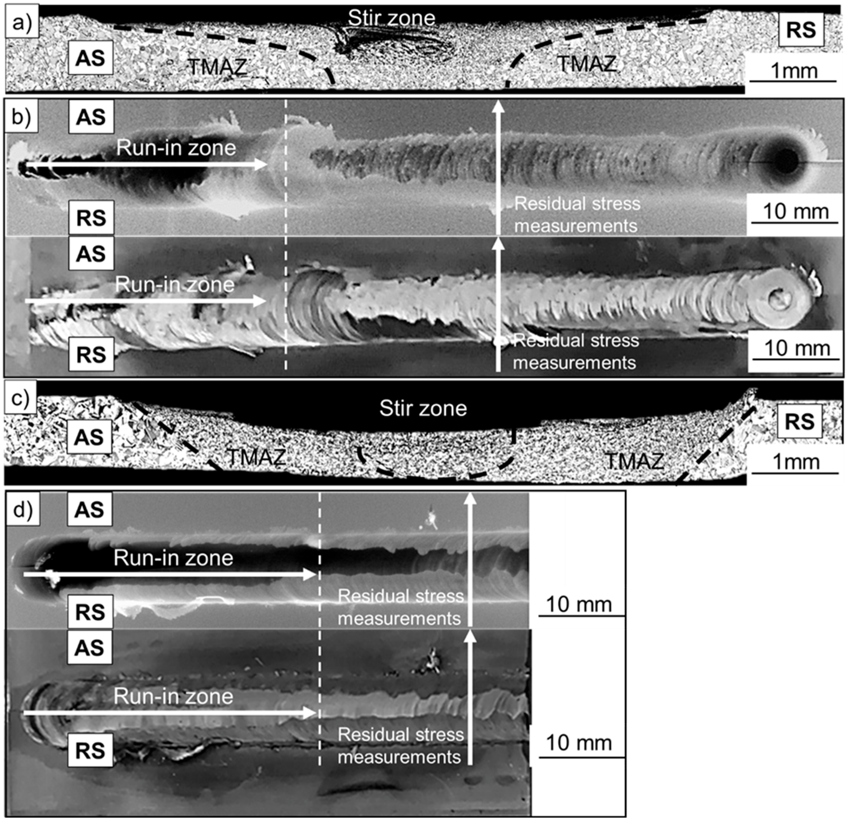
3.2. FSW Experiments

Figure 4 presents the macros of the cross-section for the FSW specimens of both alloys and the respective images of the X-ray radiographic inspection. Complete weld penetration with no weld defects, such as tunnel defects, cracks, or pores, was exhibited. The stirring zone, which is present up to the lower end of the weld, had a fine-grained structure due to the FSW-specific high plastic deformations, in accordance with [12]. The advancing side (“AS”, i.e., direction of tool rotation in welding direction) showed a “white band” due to very high deformation of the material combined with particles (W or La2O3 as the tool material) caused by tool wear, cf., [6]. This area is characterised in the literature by increased hardness [7], and may be a potential origin for premature component failure. The so-called thermo-mechanically affected zone (TMAZ) also showed grain refinement, and was more pronounced on the retreating side (RS, i.e., direction of tool rotation against the welding direction) than on the AS. The selected FSW process parameters and tools appeared to be well suited for processing the CoCrFeMnNi HEA. Similar welding results occurred for the CoCrNi MEA and a weld without recognisable weld imperfections. However, as can be seen from Figure 4c,d, a slightly higher compressive force or deeper depth of entry of the tool on/into the specimen was necessary to set the required temperature. As a result, a reduction in the weld thickness compared to the base metal was obvious. In contrast to the HEA, the TMAZ of the MEA weld extended over the entire sheet thickness, and no “white band” formed in the stir zone.
In Figure 5, the residual stress profiles of the HEA and MEA friction stir welds on the top and bottom sides are shown. Due to the significant grain refinement in the stir zone and TMAZ, small scatter bands of the analysed residual stresses in the weld zone are exhibited, in contrast to the TIG welds. Transverse residual stresses at the top and root side of the HEA welds showed values between 0 to −100 MPa in the weld (zones where pin and shoulder affected the weld). The residual stresses increased towards the base metal up to +100 MPa at the AS, and up to +200 MPa at the RS. The higher stresses at the RS are assumably due to the higher relative speed between the tool and workpiece during the welding process, in connection with higher heat input and higher initiation of restrained shrinkage during the cooling process.
In the weld zone of the HEA, longitudinal residual stresses of up to +300 MPa at the magnitude of the Rp0.2 strength of the material [26] occurred at top side, and up to +150 MPa at the root side, as a result of hindered shrinkage after welding due to the clamped specimens. The larger width of the weld zone at the top side effected higher welding stresses compared to the root side. In the direction of the BM, the longitudinal residual stresses decreased to values between −200 MPa and −350 MPa because of compensating compressive residual stresses. A similar result was obtained with the MEA welds. Due to the higher hardness of the material and the resulting higher necessary contact pressure of the welding tool in connection with a more pronounced weld zone and TMAZ extending over the entire specimen thickness, the residual stress profiles were higher and broader overall. The transverse residual stresses increased in the BM, especially on the upper side of the specimen, up to about +350 MPa (about Rp0.2 strength of the material). The longitudinal residual stresses also reached up to +350 MPa on the upper side of the specimen in the welding area and the HAZ, and +150 MPa on the root side of the specimen. Pronounced compensating residual compressive stresses up to -300 MPa in the BM were only observed on the root side in contrast to the HEA weld. At the RS of the upper side of the specimen, the longitudinal residual stresses remained in the tensile range at about +100 to +150 MPa.
These results are in good agreement with those of austenitic 304 L stainless steel [16,17]. In the weld, higher tensile stresses in the longitudinal direction than in the transverse direction on the upper side occurred. Furthermore, the stresses decreased with increasing distance from the welded zone towards compressive values at the HEA. However, in contrast to the literature [16,17], an increase in tensile residual stresses outside the weld in the transverse direction was observed, which is supposedly due to small specimen size and high restraints during welding.
The differences in the residual stress characteristics in both TIG and FSW process are due to the different origins of the residual stresses. In the case of TIG, this is primarily due to shrinkage restraint, and in the case of FSW, it is primarily due to the high plastic deformation. This is particularly evident in the pronounced directional dependence of the tensile residual stresses. With TIG, high tensile residual stresses were in the centre in both directions. For FSW, longitudinally high tensile residual stresses and transversely low tensile residual stresses were located in the centre. In the transversal direction, higher tensile residual stresses were found next to the weld seam.
It is difficult to draw a recommendation of which process (TIG or FSW) would be optimal in terms of residual stress formation in the shown materials. With TIG, the highest tensile residual stresses, which are expected to be most critical, could not be determined exactly in the weld centre, due to the large and orientated grains in the weld metal. Nonetheless, basically, both processes showed tensile residual stresses up to values at the magnitude of the yield strength. Differences were observed in the transverse direction. For FSW, the tensile residual stresses were increased in the base material; in contrast, for TIG, this was the case in the weld metal. In addition, the residual stress state could be influenced by a proper post-weld heat treatment. However, this needs to be investigated further, especially since no studies on the influence of heat treatment on the residual stress state in HEAs have been published so far.

4. Summary and Conclusions

The investigation of residual stresses due to TIG and FSW joining on a CoCrFeMnNi HEA and a CoCrNi MEA led to the following conclusions:
(1)
The results basically show that with the selected tool, process, and parameters, CoCrFeMnNi HEA and CoCrNi MEA welds can be produced that do not show any impermissible defects upon visual inspection and light microscopic examination of the transverse sections. In summary, both alloys showed good weldability using the TIG and FSW process, as stated in other studies.
(2)
Defect-free welds were obtained with specimens with considerable dimension and restraint conditions, allowing residual stress analyses to be carried out at the weld seams.
(3)
The columnar dendritic solidification (large, oriented grains) did not allow a proper determination of residual stresses by XRD in TIG WM. The high compensating longitudinal residual compressive stresses in the HAZ and the base metal indicate high tensile stresses up to the material strength in the TIG WM area of HEA and MEA; meanwhile, the transverse residual stresses in the base metal were low (approx. 0 MPa), and increased at the top side in the weld area and decreased on the root side into compression (HEA), or vice versa (MEA).
(4)
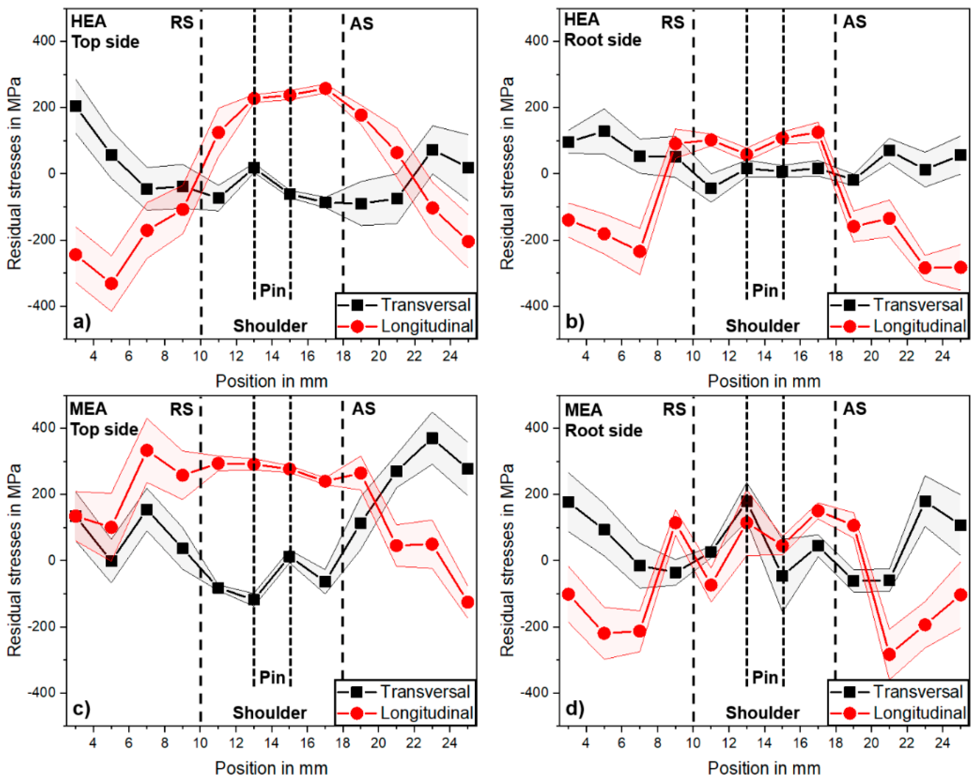
The fine-grained structure of friction stir WM allowed accurate residual stress analysis. The longitudinal FSW-generated residual stresses for both MEA and HEA were similar to the TIG welds, with compressive stresses (base material) and tensile stresses in yield strength level (WM). The higher force for FSW processing of the harder MEA resulted in a significantly wider residual stress profile, transverse to the welding direction. In contrast to the TIG, the transverse residual stresses (WM) were close to 0 MPa, and increased in the direction of the base metal, in the MEA, up to the yield strength level.

Author Contributions

Conceptualization, T.R. and D.S.; methodology, T.R. and D.S.; formal analysis, T.R.; investigation, T.R.; resources, T.R. and D.S.; data curation, T.R.; writing—original draft preparation, T.R. and D.S.; writing—review and editing, T.R., D.S. and M.R.; visualization, T.R. and D.S.; supervision, D.S. and M.R.; project administration, T.R. All authors have read and agreed to the published version of the manuscript.

Funding

This research received no external funding.

Acknowledgments

This study was carried out within the project “SURDIA—Surface Degradation of Innovative Alloys” at Bundesanstalt für Materialforschung und -prüfung (BAM), Berlin, Germany. The authors would like to thank G. Laplanche (Ruhr-Universität Bochum, Germany) and M. Schneider (MTU Aero Engines Munich, Germany) for providing the test materials; G. Oder, M. Grunwald, J. Biermann, T. Michael, A. Boerner, and D. Stock (all with BAM) for the metallography, X-ray radiographic, EDM, and support during the experiments.

Conflicts of Interest

The authors declare no conflict of interest.

References

  1. Yeh, J.W.; Chen, S.K.; Lin, S.J.; Gan, J.Y.; Chin, T.S.; Shun, T.T.; Tsau, C.H.; Chang, S.Y. Nanostructured high-entropy alloys with multiple principal elements: Novel alloy design concepts and outcomes. Adv. Eng. Mater. 2004, 6, 299–303. [Google Scholar] [CrossRef]
  2. Manzoni, A.M.; Glatzel, U. High-Entropy Alloys: Balancing Strength and Ductility at Room Temperature. Ref. Modul. Mater. Sci. Mater. Eng. 2020, 2, 441–453. [Google Scholar] [CrossRef]
  3. Miracle, D.B.; Senkov, O.N. A critical review of high entropy alloys and related concepts. Acta Mater. 2017, 122, 448–511. [Google Scholar] [CrossRef] [Green Version]
  4. Rhode, M.; Richter, T.; Schroepfer, D.; Manzoni, A.M.; Schneider, M.; Laplanche, G. Welding of high-entropy alloys and compositionally complex alloys-an overview. Weld. World 2021, 65, 1645–1659. [Google Scholar] [CrossRef]
  5. Laplanche, G.; Kostka, A.; Reinhart, C.; Hunfeld, J.; Eggeler, G.; George, E.P. Reasons for the superior mechanical properties of medium-entropy CrCoNi compared to high-entropy CrMnFeCoNi. Acta Mater. 2017, 128, 292–303. [Google Scholar] [CrossRef]
  6. Park, S.; Nam, H.; Na, Y.; Kim, H.; Moon, Y.; Kang, N. Effect of Initial Grain Size on Friction Stir Weldability for Rolled and Cast CoCrFeMnNi High-Entropy Alloys. Met. Mater. Int. 2020, 26, 641–649. [Google Scholar] [CrossRef]
  7. Park, S.; Park, C.; Na, Y.; Kim, H.-S.; Kang, N. Effects of (W, Cr) carbide on grain refinement and mechanical properties for CoCrFeMnNi high entropy alloys. J. Alloys Compd. 2019, 770, 222–228. [Google Scholar] [CrossRef]
  8. Richter, T.; Giese, M.; Rhode, M.; Schroepfer, D.; Michael, T.; Fritsch, T. Influence of Surface Preparation on Cracking Phenomena in TIG-Welded High and Medium Entropy Alloys. J. Manuf. Mater. Process. 2021, 6, 5. [Google Scholar] [CrossRef]
  9. Nam, H.; Park, S.; Chun, E.-J.; Kim, H.; Na, Y.; Kang, N. Laser dissimilar weldability of cast and rolled CoCrFeMnNi high-entropy alloys for cryogenic applications. Sci. Technol. Weld. Join. 2019, 25, 127–134. [Google Scholar] [CrossRef]
  10. ISO/TR 581:2005; Weldability—Metallic materials—General Principles. Beuth publishing: Berlin, Germany, 2005.
  11. Xu, N.; Song, Q.; Bao, Y. Microstructure evolution and mechanical properties of friction stir welded FeCrNiCoMn high-entropy alloy. Mater. Sci. Technol. 2019, 35, 577–584. [Google Scholar] [CrossRef]
  12. Heidarzadeh, A.; Mironov, S.; Kaibyshev, R.; Çam, G.; Simar, A.; Gerlich, A.; Khodabakhshi, F.; Mostafaei, A.; Field, D.P.; Robson, J.D.; et al. Friction stir welding/processing of metals and alloys: A comprehensive review on microstructural evolution. Prog. Mater. Sci. 2020, 117, 100752. [Google Scholar] [CrossRef]
  13. DIN EN ISO 6520—2; Einteilung von Geometrischen Unregelmäßigkeiten an Metallen, Pressschweißungen. Beuth Verlag GmbH: Berlin, Germany, 2001.
  14. Nitschke-Pagel, T.; Wohlfahrt, H. Residual Stresses in Welded Joints—Sources and Consequences. Mater. Sci. Forum 2002, 404–407, 215–226. [Google Scholar] [CrossRef]
  15. Zerbst, U. Application of fracture mechanics to welds with crack origin at the weld toe—A review. Part 2: Welding residual stresses. Residual and total life assessment. Weld. World 2019, 64, 151–169. [Google Scholar] [CrossRef]
  16. Reynolds, A.P.; Tang, W.; Gnaupel-Herold, T.; Prask, H. Structure, properties, and residual stress of 304 L stainless steel friction stir welds. Scr. Mater. 2003, 48, 1289–1294. [Google Scholar] [CrossRef]
  17. Zhu, X.K.; Chao, Y.J. Numerical simulation of transient temperature and residual stresses in friction stir welding of 304 L stainless steel. J. Mater. Process. Technol. 2004, 146, 263–272. [Google Scholar] [CrossRef]
  18. Singh, K.; Singh, G.; Singh, H. Review on friction stir welding of magnesium alloys. J. Magnes. Alloy. 2018, 6, 399–416. [Google Scholar] [CrossRef]
  19. Richter, T.; Schröpfer, D.; Rhode, M.; Börner, A. Rührreibschweißen von Hoch- und Mittelentropie-Legierungen. In Tagungsband 4. Symposium Material Technik; Clausthaler Znetrum für Materialtechnik: Clausthal Zellerfeld, Germany, 2021; p. 974. [Google Scholar]
  20. ISO 6507-1:2018; Metallische Werkstoffe– Härteprüfung nach Vickers—Teil 1: Prüfverfahren. Beuth Verlag GmbH: Berlin, Germany, 2018.
  21. Richter, T.; Schroepfer, D.; Rhode, M.; Boerner, A.; Neumann, R.S.; Schneider, M.; Laplanche, G. Influence of machining on the surface integrity of high- and medium-entropy alloys. Mater. Chem. Phys. 2022, 275, 125271. [Google Scholar] [CrossRef]
  22. Laplanche, G.; Volkert, U.F.; Eggeler, G.; George, E.P. Oxidation Behavior of the CrMnFeCoNi High-Entropy Alloy. Oxid. Met. 2016, 85, 629–645. [Google Scholar] [CrossRef]
  23. Withers, P.J.; Turski, M.; Edwards, L.; Bouchard, P.J.; Buttle, D.J. Recent advances in residual stress measurement. Int. J. Press. Vessel. Pip. 2008, 85, 118–127. [Google Scholar] [CrossRef]
  24. Zaddach, A.J.; Niu, C.; Koch, C.C.; Irving, D.L. Mechanical Properties and Stacking Fault Energies of NiFeCrCoMn High-Entropy Alloy. Jom 2013, 65, 1780–1789. [Google Scholar] [CrossRef]
  25. Laplanche, G.; Gadaud, P.; Bärsch, C.; Demtröder, K.; Reinhart, C.; Schreuer, J.; George, E.P. Elastic moduli and thermal expansion coefficients of medium-entropy subsystems of the CrMnFeCoNi high-entropy alloy. J. Alloys Compd. 2018, 746, 244–255. [Google Scholar] [CrossRef]
  26. Wu, Z.; David, S.A.; Leonard, D.N.; Feng, Z.; Bei, H. Microstructures and mechanical properties of a welded CoCrFeMnNi high-entropy alloy. Sci. Technol. Weld. Join. 2018, 23, 585–595. [Google Scholar] [CrossRef]
Figure 1. Welding experiment setup: (a) TIG, (b) FSW and (c) tool goemetrie.
Jmmp 06 00147 g001
Figure 2. Macros of the weld cross-section of the TIG welds for the HEA (a) and MEA (c), and the respective images of the X-ray radiographic inspection and surface images for the HEA (b) and MEA (d).
Jmmp 06 00147 g002
Figure 3. Longitudinal and transversal residual stress profiles of the TIG welds of HEA at weld top (a) and root (b) side, and of the MEA at weld top (c) and root (d) side.
Jmmp 06 00147 g003
Figure 4. Macros of the weld cross-section of the friction stir welds for the HEA (a) and MEA (c), and the respective images of the X-ray radiographic inspection and surface images for the HEA (b) and MEA (d).
Jmmp 06 00147 g004
Figure 5. Longitudinal and transversal residual stress profiles of the friction stir welds of HEA at weld top (a) and root (b) side, and of the MEA at weld top (c) and root (d) side.
Jmmp 06 00147 g005
Table 1. Chemical composition and hardness (HV 0.5) of both alloys used in the welding experiments.
at.%CoCrFeMnNiHV0.5
HEA19.720.719.720.119.9130 ± 3
MEA33.034.3--32.7187 ± 6
Table 2. Welding parameters for TIG welding tests.
Basic Current Peak Current Arc VoltageShielding Gas
35 A90 A10 VI1-Ar/25 l × min−1
Pulse frequencyWelding speedHeat inputRoot shielding gas
4 Hz300 mm × min−10.133 kJ × mm−1R1-ArH-7.5
Electrode typeElectrode diameterArc length
WR022.4 mm2.5 mm
Table 3. FSW parameters.
Rotation SpeedWelding SpeedInclination Angle
3000 min−1100 mm × min−1
Test implementationShielding gasTool material
Position controlledNo shielding gasW-alloy with
1.5 wt% La2O3
Table 4. Parameters for XRD residual stress analysis.
Measuring ModeRadiationDetectorDiffraction Line2Θ Angle
sin2ψMn-KαLinear solid-state (311)156°
Collimator ᴓTube powerψ–tiltingψ-stepMeasuring time
3 mm30 kV/6.7 mA0° bis ± 45°92 s
Publisher’s Note: MDPI stays neutral with regard to jurisdictional claims in published maps and institutional affiliations.

