1. Introduction
As an advantageous materials joining method, friction stir welding (FSW) has been included in many premier engineering designs across the aerospace, nautical, energy, automotive, and other industries. The process, invented by The Welding Institute (TWI), includes a welding tool, comprised of a shoulder and concentric probe, that is plunged onto a seam while rotating [
1,
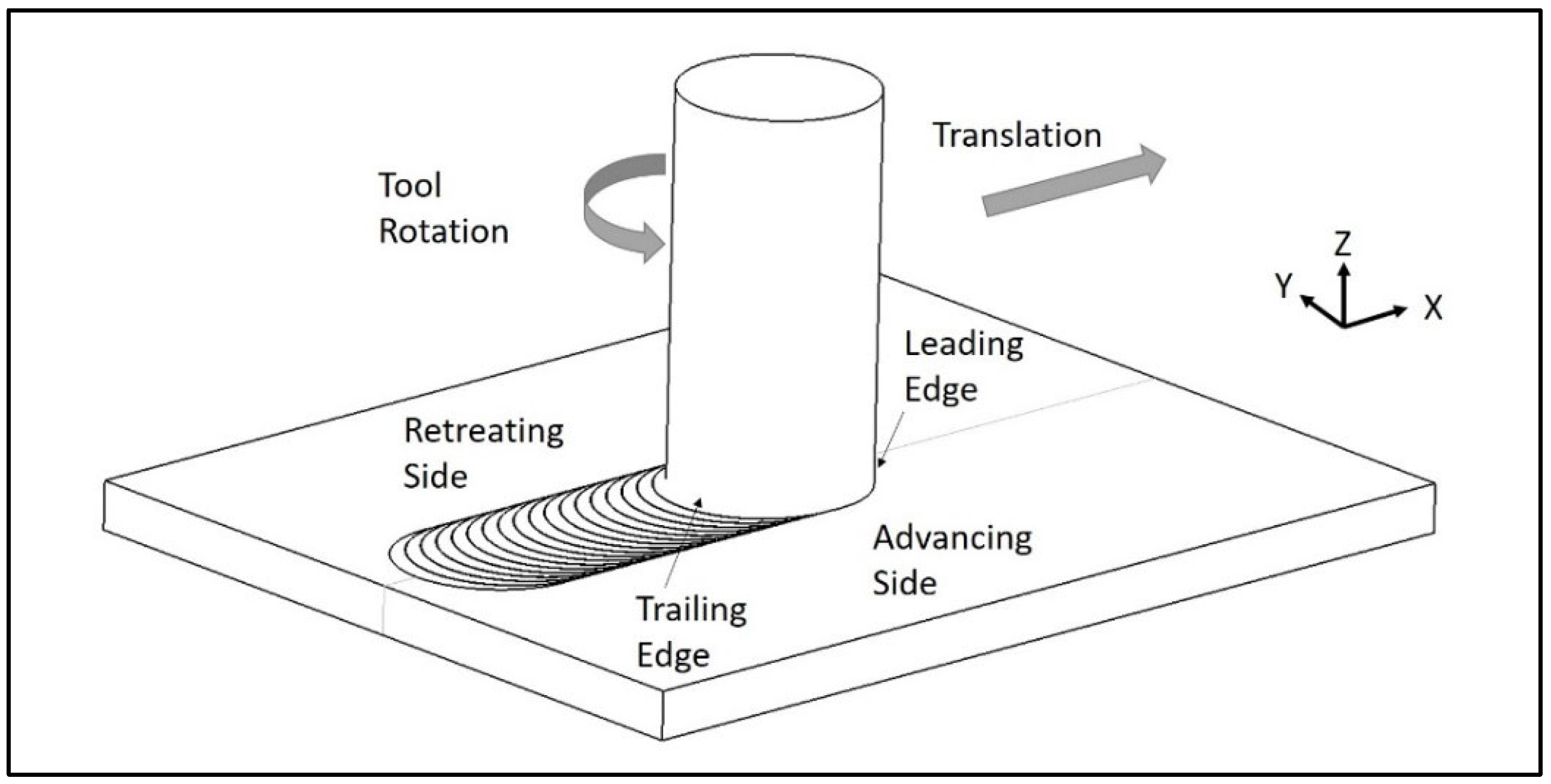
2]. Once the shoulder has engaged the workpieces then the tool traverses in a defined path. The heat from friction and plastic deformation coupled with the forging force of the tool results in a consolidated joint between the two workpieces. An example schematic of FSW is shown in
Figure 1. FSW can be applied to other workpiece configurations such as lap, T-joint, and others for a wider range of applications [
3]. Since there are no process gases, no wires nor consumables, and the process has been shown to require less energy than traditional fusion welding, this solid-state welding process is defined as an environmentally friendly metals joining process [
4]. Although FSW provides a very elegant solution to join a myriad of materials and combinations, careful implementation of the process is executed to ensure a metallurgically sound bond between the workpieces. Many researchers have developed models to replicate the FSW process in order to determine correct welding parameters such as spindle speed, welding speed, tool tilt, and others [
5,
6,
7]. Other researchers have correlated defect size to welding parameters to select parameters that minimize defect presence [
8,
9].
Industries that use any type of welding often require a non-destructive evaluation (NDE) method to verify that joints are defect-free [
10]. Many researchers have investigated different NDE methods to locate defects in FSW including: acoustic emission analysis, thermal image analysis, eddy current probe analysis, ultrasonic and phased array evaluation, liquid penetrant evaluation, and radiographic analysis [
11,
12,
13,
14,
15,
16,
17,
18,
19]. Ultrasonic and radiographic NDE are used as the standard for many industries [
20]. Most of the NDE methods listed above are all secondary manufacturing processes and increase the cost to manufacture products because of additional time, machinery, training, labor, or costs associated with evaluation by a third-party company. In the early development of FSW, the process was more readily applied in the aerospace industry, where production volumes are significantly lower than in other industries such as the automotive industry. In the last 10 years, significant developments have pushed FSW to the point that it is a viable material joining method for high-volume industries. Within a high-volume production setting, small improvements in scrap or cycle time manifest extreme cost savings. Reducing the time for NDE for a high-volume application would be very beneficial to any manufacturer [
21]. To capture the potential savings in secondary NDE methods, in-process NDE, which evaluates the welding forces from the tool spindle, has been under development since 2004 [
22]. Most of these approaches focus on defining a link between specific frequencies in force measurements to internal defects. Because the analysis of welding forces could be implemented during the welding process, there is great potential to reduce secondary process costs associated with more traditional NDE methods.
Several evaluations of in-process force-based NDE methods have been reported with varying success in identifying volumetric FSW defects. Balasubramanian demonstrated that feedback forces in the
X-axis and
Y-axis directions are periodic in nature, and that striations of material flow match peaks of the process forces [
23]. Later, Morihana used discrete fast Fourier transforms (FFT) on the
X-axis and
Y-axis forces and found a correlation between subharmonic amplitude peaks and volumetric defects. In these studies, the spindle speed was defined as the fundamental frequency [
22,
24]. Boldsaikhan continued this work by developing a program that used an artificial intelligence (AI) to build a neural network (NN) designed to be trained to identify spectral patterns that were related to defects [
25]. Later, a validation of Boldsaikhan’s program was performed by Britos. Britos made a comparison between radiography and ultrasound NDE methods to the NN method. The results of this study found that NN was more sensitive in detecting smaller voids than the other NDE methods and was 92.7% accurate overall [
10,
26]. Recently, others have also used artificial intelligence to analyze the frequency content of force signals to detect defects in FSW [
27,
28,
29]. This development has also included in-line applications of this technology for industry [
30]. However, all studies reporting the use of a NN required training for every combination of material, welding machine, thickness of material, and parameters. This is largely due to the fact that the neural networks are trained to recognize specific connections between exact frequencies and defects that would be altered if any variation from the training set was made. As such, this methodology relies on a deterministic link between a single force response to the formation of a defect, and any deviation from the training set negates the entire correlation. As stated by Babalola [
31], industry needs a NDE method that can be applied in multiple materials, thicknesses, and be easily adopted by a manufacturing line. Since statistical neural networks limit the understanding of why certain spectral data are related to defects, several more recent studies have focused on understanding a physics-based approach to deterministically link spindle force response to the formation of internal defects. Franke studied the influence that tool geometry has on the spectral data from in-process forces. This study showed that if a tool’s pin was not aligned with the axis of rotation, then larger oscillations occurred in the force signals. In addition, if the shoulder was not orthogonal to the axis of rotation, then extra shifts in the force data would occur each revolution with the changing shoulder depth [
32]. Guan noted a similar finding by simulating and measuring forces of eccentric motion of a FSW tool [
33]. Finally, Franke noted how machine compliance would affect how the force signals respond and are measured while material is being welded, implying that the application of the same defect detection method would need to be tailored to the specific machine and force measurement system based on variations of compliance from machine to machine.
The studies cited above have built a foundation that recognizes how force-based analysis could be an extremely cost-effective detect defection method in industrial FSW. However, the focus of all previous in-process NDE methodologies focused on a deterministic link between specific in-process force spectra to defect formation. In reality, variation of machine compliance, process parameters associated with active force or temperature control, and regular in-process development all eliminate the use of a deterministic approach to in-process force-based defect detection. The ideal NDE method would eliminate post processes and be general enough to work across a wider range of welding environments. Development to achieve such an NDE method should include a wide range of welding speeds. In the experiments from the cited studies above, the average welding speed is 650 mm/min in mostly heat-treatable aluminum alloys including: AA7075–T6 and T7, AA2024–T3 and AA6061–T6 with thicknesses ranging from 4 mm to 6.35 mm [
22,
24,
25,
32,
34]. In order to be applicable to industrial application, research should also include applications that join thinner materials at faster welding speeds [
35], which are particularly relevant to high-volume industries such as the automotive industry.
The approach of the current work moves away from a discrete understanding that a particular frequency is associated with the formation of a defect by recognizing that in-process force response to FSW is stochastic by nature. This recognition, that force response to FSW is stochastic, enables a detection methodology that is no-longer tied to a discrete link between specific force spectra and the formation of a defect. An evaluation of power spectral density (PSD) of force spectra to indiscriminately link responses of process forces to non-defective and defective regions is presented herein. The use of PSD enables an evaluation of weld forces even amidst dynamic process changes and variation in boundary conditions, which was previously not achievable using discrete spectral analysis. The goal of the current work is to demonstrate a more robust methodology for applying in-process, force-based NDE for FSW. The purposes of the current study are: to introduce a novel inline welding process of force-based defect detection in FSW using PSD values calculated from the welding forces and to evaluate the accuracy of the proposed methodology for defect detection in a variety of scenarios.
2. Methodology
Friction stir “butt” welds, produced from work hardenable AA5754-O [
36] with dimensions of 525 mm × 50 mm × 3.8 mm, were evaluated for this study.
Figure 2 depicts an example weld. Position control was used for all welding with a constant spindle speed of 1600 RPM (26.67 Hz). All welds were manufactured on a Bond Technologies (Elkhart, IN, USA) supported B&R controlled RM FSW machine with a maximum capability of 2250 RPM spindle speed, 3500 mm/min welding speed, 100 kN forge load, 45 kN limit for all other axes, 10 degrees backward tilt, and workspace of 3 m × 0.02 m × 0.8 m. The traverse speed and welding tilt varied throughout the experiments and are included in
Table 1. The clamping method is shown in
Figure 3. Dowel pins and set screws constrained the material in plane to the welding direction, and two mild steel bars constrained the material downward by three toe clamps per bar. Five welds were made in each of the parameter sets shown in
Table 1, resulting in 30 total welded panels. The welding tool was made from H13 tool steel with a flat, two start scrolled shoulder, 12 mm in diameter. The threaded pin had three flats 120 degrees apart, a base diameter of 6 mm, and a length of 3.1 mm with a 10-degree taper. All welds were produced in a “bead on plate” configuration with the tool pin smaller than the material thickness, in an effort to protect the FSW tool and machine.
The
X-axis,
Y-axis
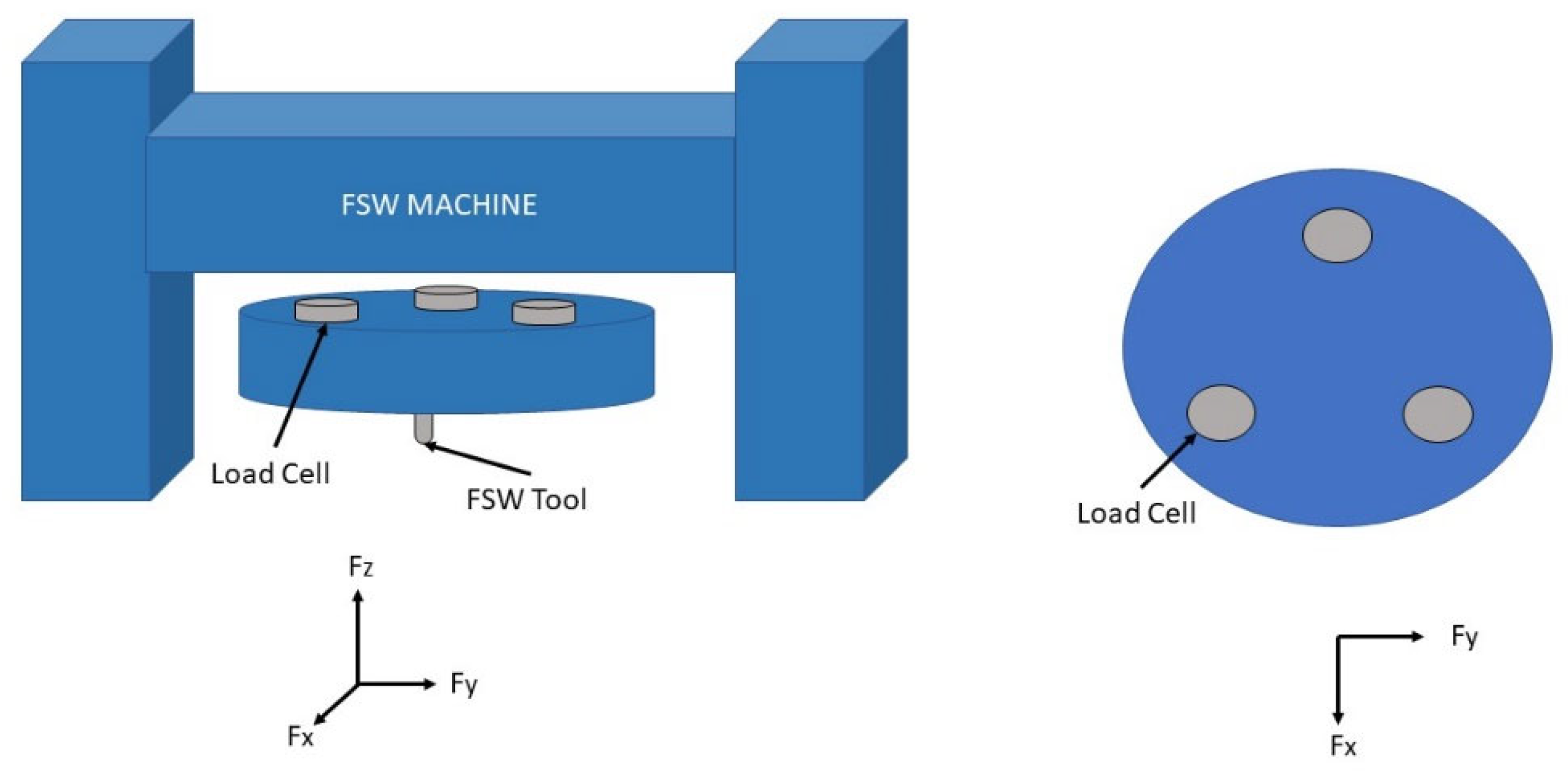
Z-axis forces and torque were sampled at a frequency of 1250 Hz. These measurements were obtained from three Kistler 9078C tri-directional load cells that are placed 120 degrees apart in between the frame of the machine and the tool as depicted in
Figure 4.Each load cell measures the three Cartesian directional forces. Other researchers have used linear dynameters [
34] in between the workpiece and fixture to measure in process forces or force measurement tables [
33]. Many current industry FSW machines only measure force along the tool axis, often called the
Z-axis force. Past force-based NDE methods use
Y-axis directional force. Thus, many current industrial machines would need to be retrofitted, or need additional exterior force measurement systems, to use past force-based NDE methods.
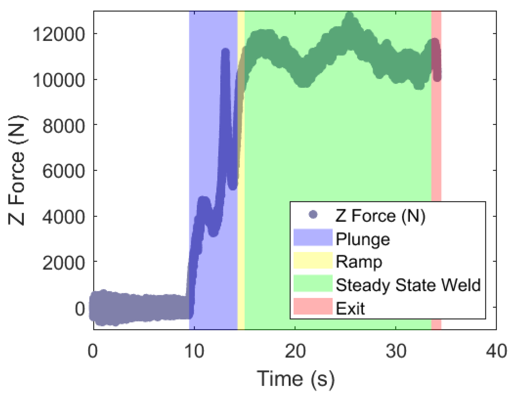
There are four segments of the weld with distinct force profiles. The first segment is the plunge of the tool into the material, the second segment is the time required for the machine to ramp up to a commanded welding speed, the third segment is a steady state part of the weld during which the traverse speed of the tool is fixed, and the final segment is the tool exit, as displayed in
Figure 5. The raw force data from the load cells were analyzed after the signals were truncated and binned. The data were truncated starting at the beginning at the steady state condition and ends at the end of the steady state segment of the weld.
Next, the truncated data were binned. The purpose of binning the signal is to create small enough data sets, so each bin included a portion of the signal that has a nonvariant mean. Reducing the size of the bins also increases the fidelity of frequency content calculations. The binned data sets are used in a spectrogram calculation, which outputs a set of values that represent the power content in a range of frequencies within a time step. PSD calculations for a specific frequency bin,
, are equivalent to the squared FFT amplitude,
, normalized by the size of the frequency bin,
, as found in Equation (1).
PSD values were used, instead of FFT amplitude values, to: (1) eliminate the effects of different sample bin sizes and (2) to better compare the stochastic effects in the physical welding process. In contrast, all previous spectral NDE methods have used Fourier Transform amplitude data to compare defective and non-defective welds to define a detection method in friction stir welds.
PSD calculations require equal time steps in between measurements. The transition from an analog to digital signals of the raw measured data included inconsistent time steps that averaged to 1 kHz. Therefore, linear interpolation between points was done to create a dataset that had a consistent time step of 0.0004 s, as if all signals were sampled at 2.5 kHz. Then the spectrogram function in MATLAB calculated the one-sided PSD data [
37]. The parameters used in this function were a bin size of 2000 data points and an 85% overlap, to obtain high x position fidelity. These parameters yielded time bins that were 0.12 s apart, or a PSD value every 6 mm at the fastest traverse speed, and frequency bins that were 1.2 Hz apart. If the bin size had been larger, then longer portions of the signal would have been evaluated for each calculation, increasing the distance between position data points that could be correlated to a defect. In addition, if a lower fidelity sample rate had been used then higher frequencies would not have been captured in the data.
Two-dimensional radiographic images were acquired from Avonix Imaging, Maple Grove, MN, USA. The following equipment was used to image the samples: M2 system, internally designed and built; Nikon (Tokyo, Japan) 225 kv microfocus x-ray tube; and a Varex 1621 amorphous silicon flat panel detector (Salt Lake City, UT, USA). Image J and Adobe Photoshop were the two programs used to equate grey scales and stich the images of a single weld together. These x-ray images provided the spatial location of any defects. Thus, equally spaced distance defect logic vectors were built accordingly, with “1” interpreted as defect and “0” as defect-free. Logical vectors that represented defect locations were manually extracted from each image and converted from pixels to millimeters. After radiographic imaging, cross-sectional metallography quantified the area of a defect. An optical microscope, Olympus SZX12 (Tokyo, Japan) running Leco Paxit 2 software, provided the cross sectional images.
3. Results and Discussion
Numerous authors have demonstrated that a reduction of heat in a friction stir weld may yield wormholes or void defects in the stir zone [
24,
38]. Although 3.4 mm-thick AA5754-O is commercially welded using FSW at speeds above 2000 mm/min and spindle speeds near 1500 RPM [
39], defects were necessary to examine the PSD data associated with them. As such, a reduction of the weld temperature was sought by increasing transverse speed to yield defects in the weld. In addition, a lower tilt was used to decrease the pressure on the trailing side of the tool, which reduces the necessary downward force required to consolidate the material and avoid weld defects [
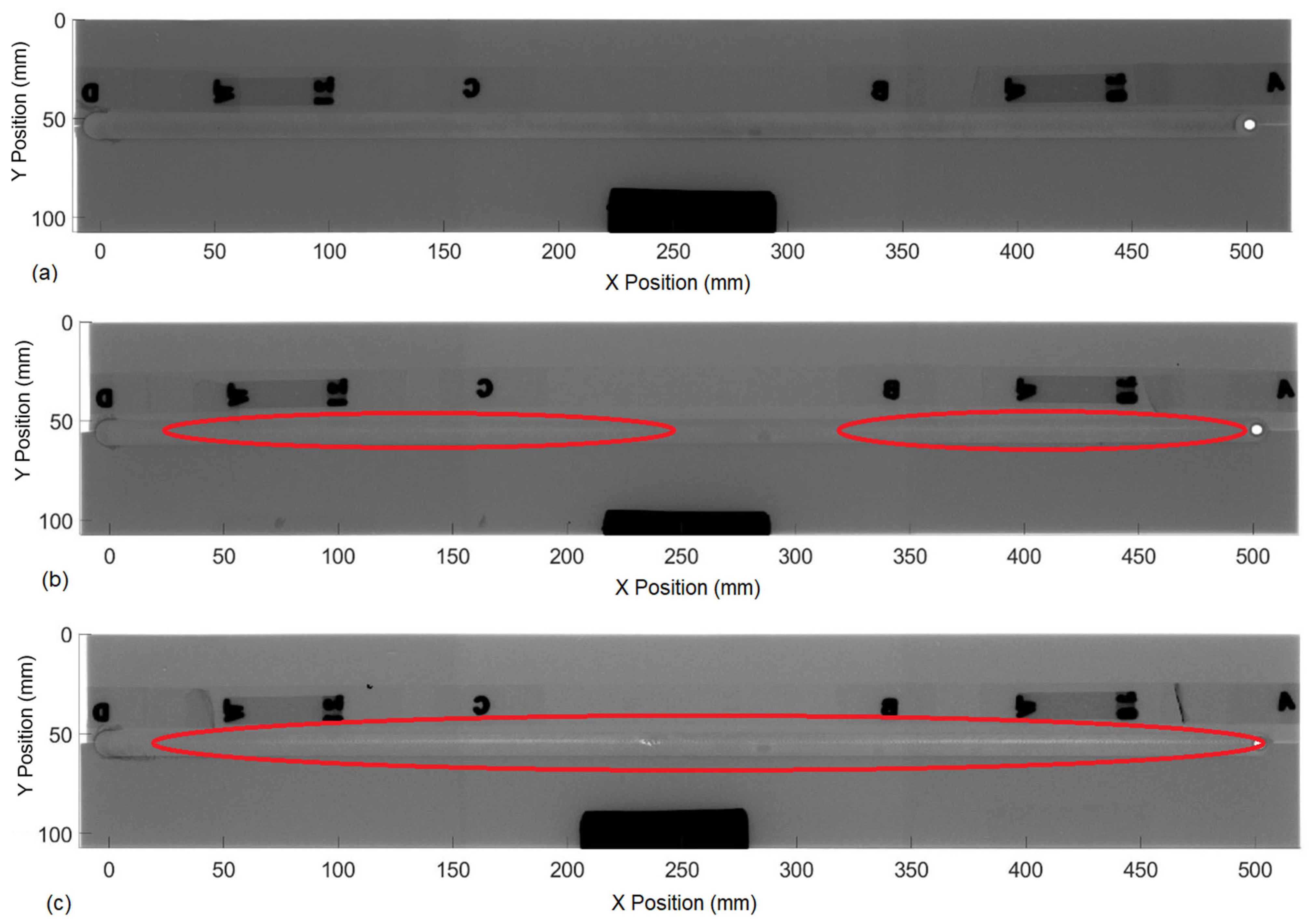
40]. These two changes to the welding parameters assured defects in the stir zone for several of the welding parameters evaluated herein. Examples of varying weld quality are found in
Figure 6. Through this discussion an example weld from the dataset will used to highlight trends found throughout. Image 6b shows that a volumetric defect opens, near 60 mm, then closes at 250 mm. Another defect later opens near 350 mm and closes at 470 mm.
The X-ray images confirmed the repeatability of each parameter set and their resulting weld quality. In addition, they provided the locations of volumetric voids; thus, enabling the ability to extract cross section samples at desired locations and to measure the defect area. An example of an optical micrograph from the weld depicted in
Figure 6c at X Position 470 mm is shown in
Figure 7. Using optical micrographs, defect sizes ranged from 0.003 mm
2 to 0.6 mm
2. However, the X-ray images were only capable of defining voids with a width of approximately 0.27 mm or larger. Using optical micrographs at the extremes of the X-ray images defect definition, defect heights ranged from 0.08 mm to 0.6 mm. Thus, the X-ray images were able to define volumetric voids whose areas were approximately 0.02 mm
2 or larger.
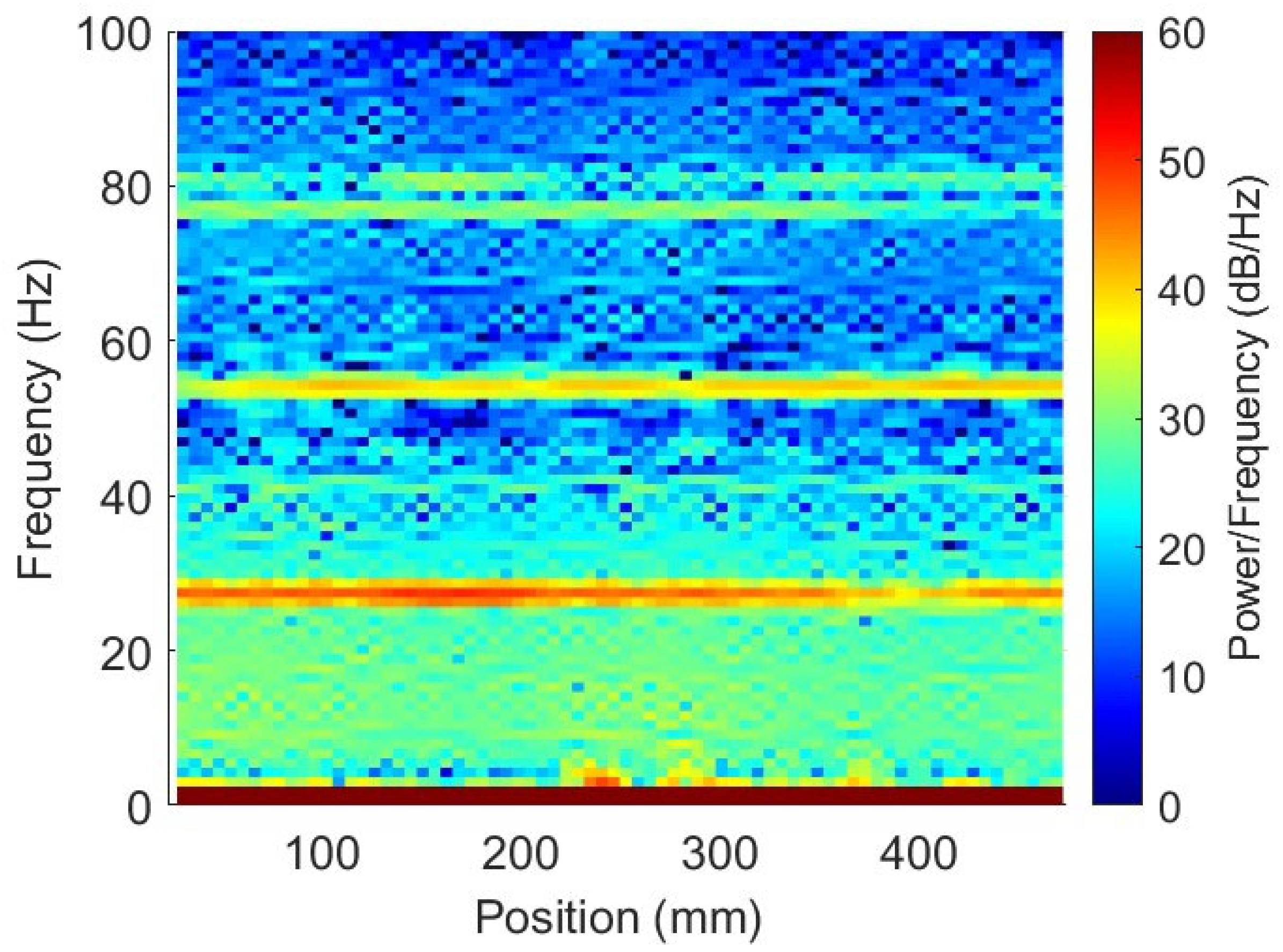
Spectrogram calculations were made in tandem with the X-ray image analysis, using the MATLAB spectrogram function and were plotted [
37]. An example of a spectrogram plot is found in
Figure 8. This function outputs three data sets: first, an array that lists the midpoint of each time bin; second, an array that lists the midpoint of each frequency bin; and third, a matrix of PSD values that corresponds to the time and frequency bins arrays. The raw data was used to convert time to
X-axis position. This conversion made the comparison between the spectrograms and the radiographic images simpler. These three outputs create a three-dimensional plot that renders the spectral changes of the welding forces for the entire weld. Each force and torque signal, from all welds, yielded a total of 120 spectral maps.
Once both the logical defect vectors and the spectral maps were built for each weld, a correlation coefficient was calculated between every combination of defect logic vector and every force or torque PSD vector for every frequency bin that is under the Nyquist frequency (0–600 Hz). The correlation coefficients were calculated using the “corrcoef” function in MATLAB. The resulting correlation coefficients identified that low frequency bins for the
Y-axis and
Z-axis forces consistently correlated to defect presence with a value greater than 0.7, or less than −0.7 for a negative correlation. There was not a consistent correlation between defect presence and the
X-axis force or torque PSD datasets. The validation of
Y-axis force spectral data correlating with defect presence is similar to Morihana’s findings [
22]. However, this is the first time that
Z-axis force spectral data has been reported to be correlated to defect presence.
The frequency bins that correlated to defect presence were analyzed to observe the differences between a defective weld and a non-defective weld. The negative correlation between defect presence and
Z-axis force spectral data suggested that defect-free welds resulted in higher spectral values than defective welds; and the positive correlation between
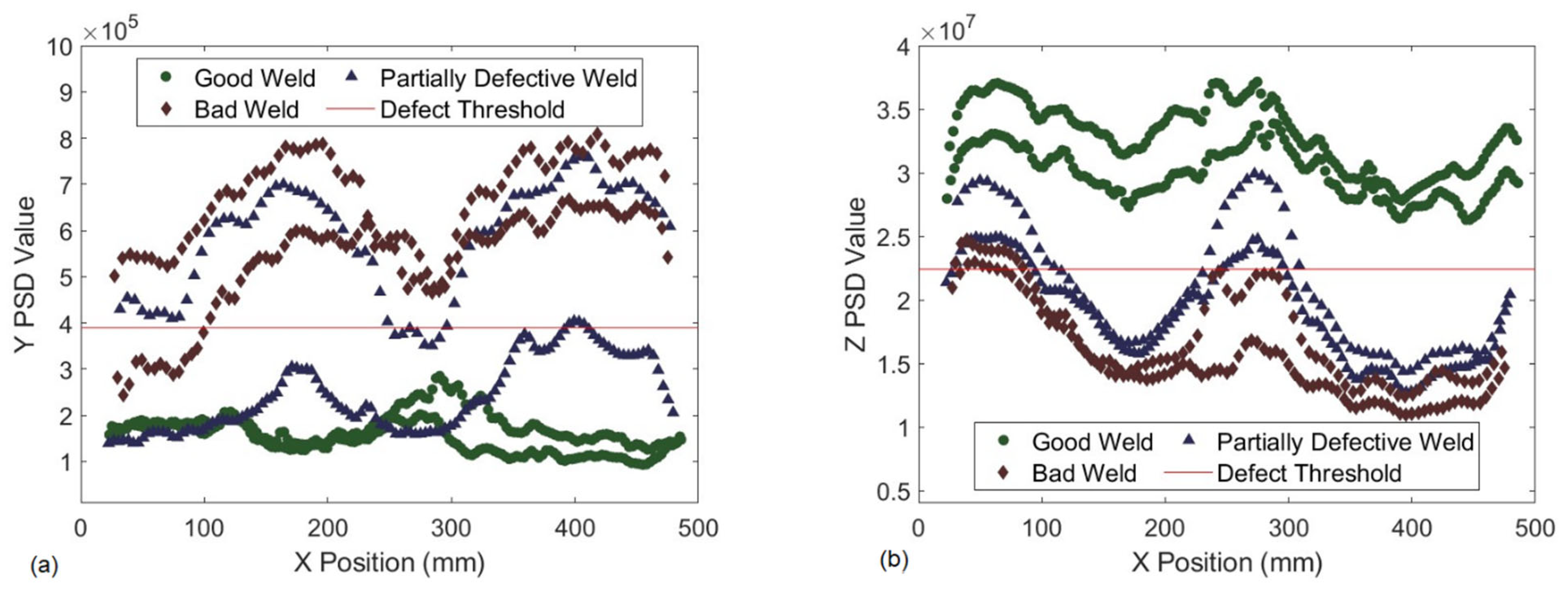
Y-axis force spectral data and defect presence suggested the opposite trend. Three out of the five welds per parameter set were used to find a threshold that could predict defect presence along the other two welds for each parameter set. The two test welds for each of the parameter sets with an arbitrary PSD value threshold are found in
Figure 9. Weld 6b, from
Figure 6, is the top blue triangle curve in
Figure 9. The arbitrary
Z-axis force PSD threshold in this plot is 2.25 × 10
7 . In the beginning of the weld the
Z-axis force PSD value is greater than the threshold until about 100 mm, predicting no defects from the start of the weld until 100 mm. The
Z-axis force PSD value stays beneath the threshold until about 230 mm, predicting a defect in that portion of the weld. From 230 mm until 350 mm the threshold suggests no defect in the weld. Near 350 mm the
Z-axis force PSD values cross the threshold again, assuming a defect again through the remainder of the weld. These predictions closely align with the defect location found in the radiographic image shown in
Figure 6. There is some error where the PSD thresholds do not match exactly with the defect location; however, slightly increasing or decreasing the threshold could reduce the error.
Das found that defective welds have higher PSD values than non-defective welds and that a defect detection method could be built analyzing force PSD values, similar to the Y PSD correlation found in this study [
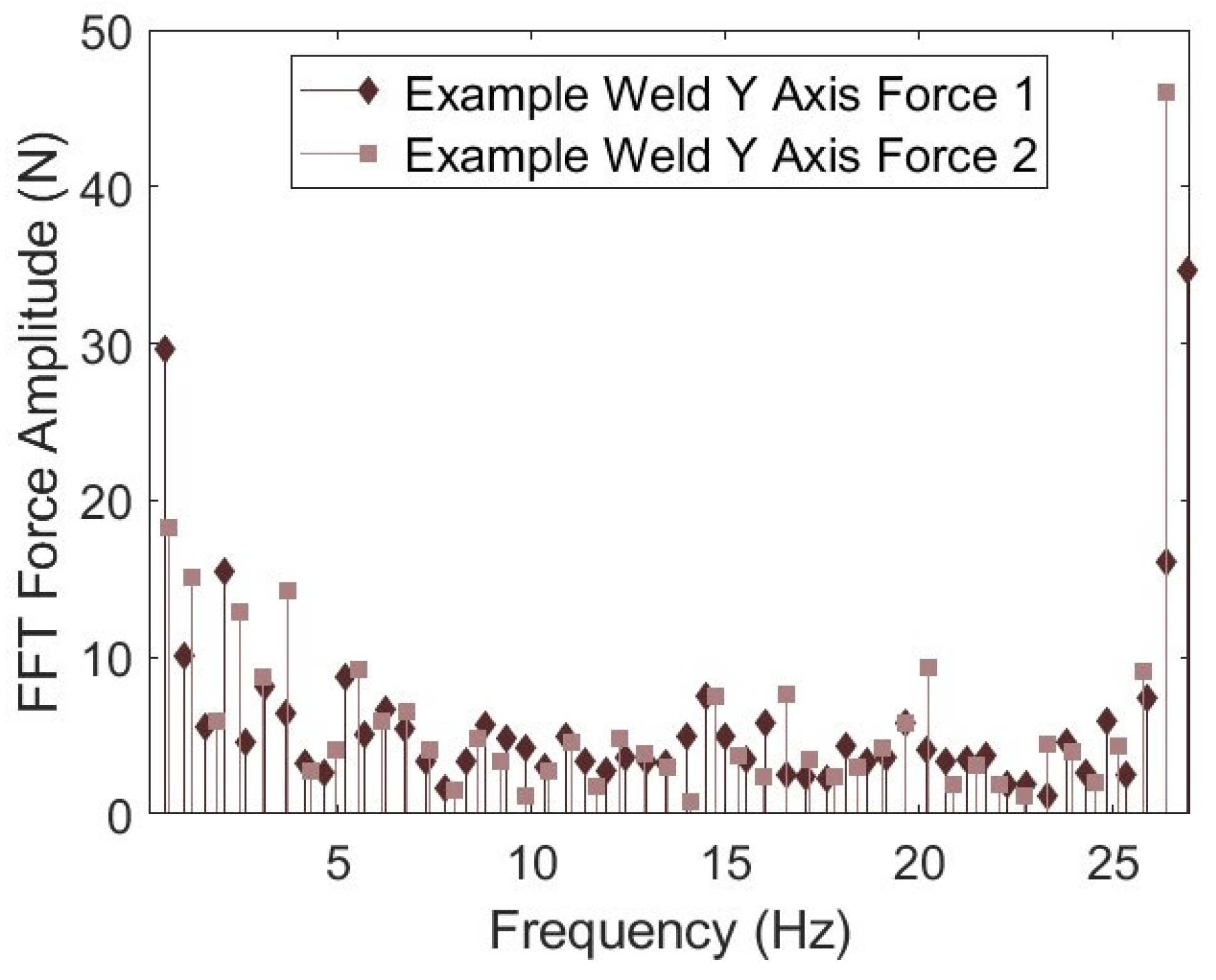
41]. However, a fully developed method using this ideology had not yet been completed until this work. The benefit of using the spectrogram function is that PSD calculations are normalized by the bin size. Thus, the noise in the signal is scaled to the contents of the corresponding bin allowing better observation of the stochastic effects of the welding process. Additionally, the spectrogram function provides a consistent frequency step across different lengths of data caused by different welding speeds of similar weld lengths. An example is shown in
Figure 10 where the FFT amplitude of the two defective welds from
Figure 9 are plotted across frequencies below the spindle speed (26.67 Hz). In this plot, the difference between the spectrograms PSD vs. FFT amplitude calculations that can be observed. The first is that the amplitude calculations are dependent on the length of the force data. Thus, the frequencies that the amplitudes are evaluated at are different depending on the amount of data provided for the calculation. This phenomenon would affect the ability to detect defects when welding speeds change, which causes different amounts of data for the same length of weld and sample frequency. Second, the difference between values at the same, or similar frequencies, range from minute to an order of magnitude different. This inconsistency limits the ability to determine defect presence per frequency and amplitude from weld to weld. However, a PSD threshold is not subject to these two issues. In addition, a PSD threshold can be tailored to accommodate the application. To find the “best” threshold, the minimum and maximum PSD values from all 30 welds were found for both the
Y and
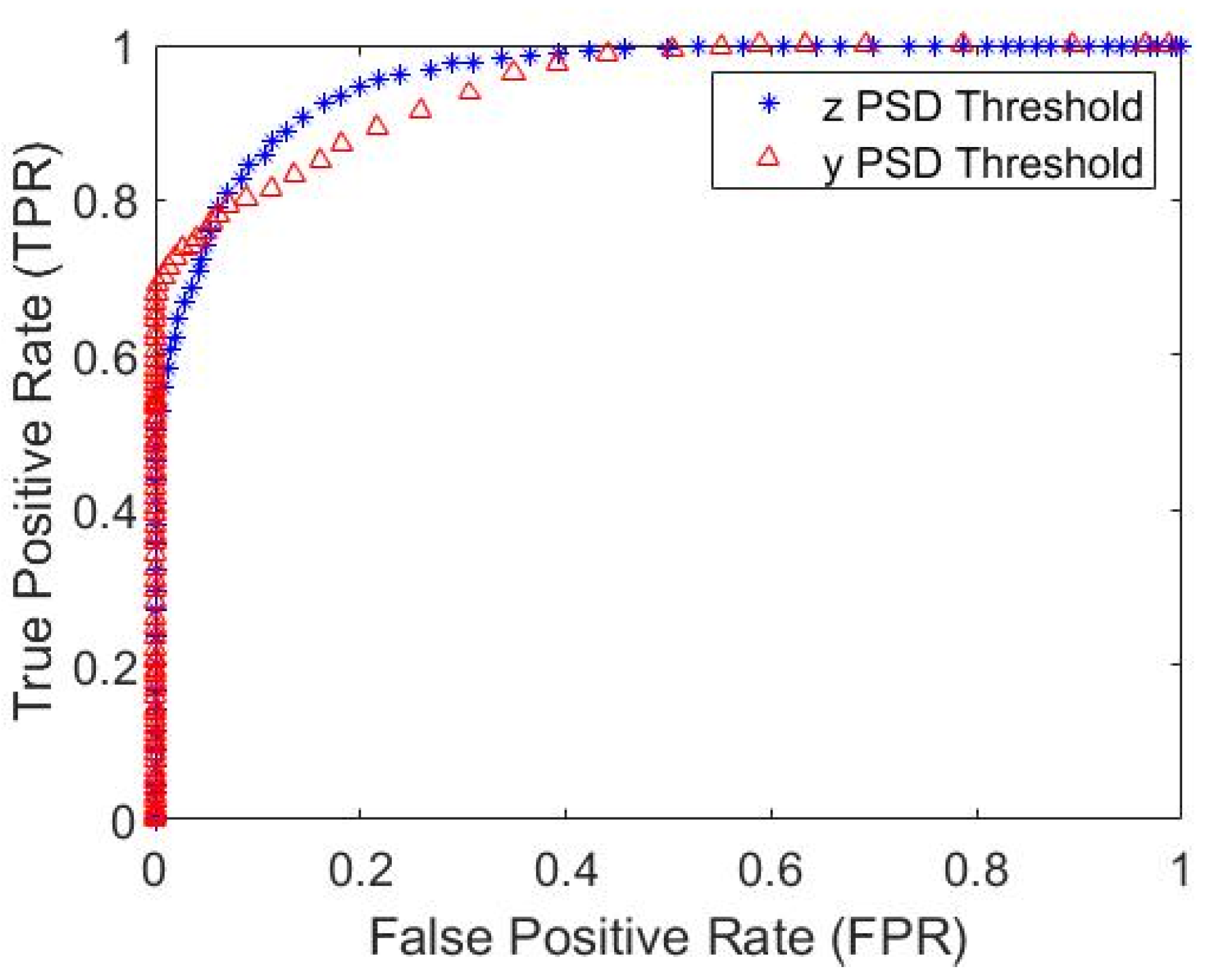
Z datasets. A total of 100 even steps between them were generated. Next, each of the 100 thresholds’ predictions and the actual defect logical vector for each weld were used to calculate a confusion matrix for each threshold. A receiver operating characteristic (ROC) curve was created, as seen in
Figure 11, from this data to showcase the differences in predicting defects using either the
Z-axis PSD or
Y-axis PSD.
The ROC plot indicates the performance of each threshold. A perfect threshold would show the true-positive rate (where the threshold correctly detects a defect—TPR) is one and the false-positive rate (where the threshold labels a defect free weld defective—FPR) is zero, which is the top left corner of the ROC plot. This perfect threshold would define every defect as a defect, 100% true positive rate, without any false positives. In most real-world applications, it is difficult to achieve a perfect threshold. Thus, many applications will choose the threshold that is the shortest distance from the upper left-hand corner in an ROC plot.
Figure 11 displays that the
Z-axis force ROC curve has slightly more ideal thresholds than the y ROC curve with a performance of 80% true positive rate and 11% false negative rate (FPR). The most ideal threshold for the
Y-axis force PDS data preforms with 70% true positive rate and 0% false negative rate. The trade-off with reducing the false positive rate is the true positive rate also decreases.
The performance of these thresholds separately is not accurate enough for industrial use; however, combining these thresholds significantly increases the ability to detect defects at any given point in the weld. All of the
Z-axis force and
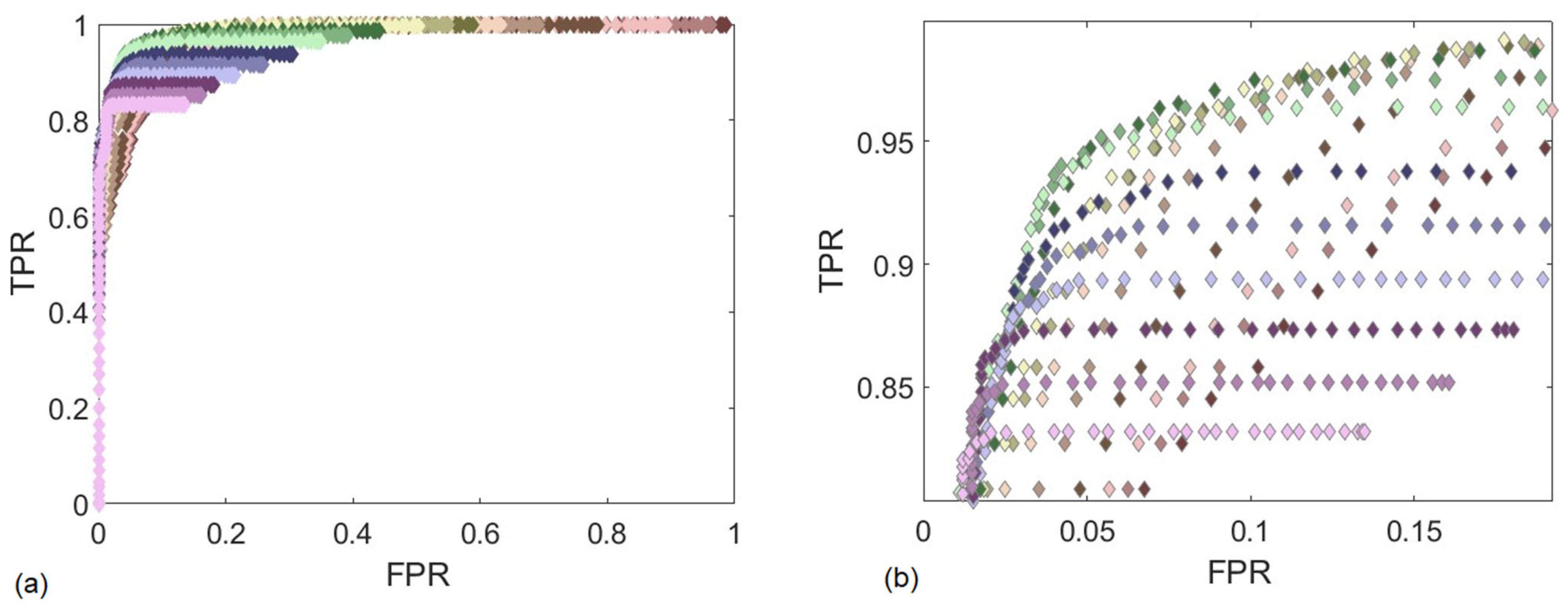
Y-axis force thresholds were combined to build a more robust ROC. The 25 best-performing ROC curves are plotted in
Figure 12. The combined, multi-axial threshold uses the logic that if the weld’s
Y-axis force PSD value was higher than the corresponding threshold
and the weld’s
Z-axis force PSD value was lower than the corresponding threshold there was a defect at that location. This combination resulted in a combined threshold that could predict defects with a 94% TPR and a 4.2% FPR.
To compare the performance of these ROC curves to another spectral NDE method, Brito’s study of Boldsaikhan’s NN resulted in 92.8% TPR and 3.6% FPR. This performance of the combined ROC curve would be sufficient in a manufacturer setting. However, in many applications the weld is an integral part of a joint; thus, if even a small section of the weld is defective the whole part is qualified unusable. Thus, additional logic was used in the combined threshold regime to apply to a weld as a whole and not spatially, or as a Go, No Go test. If
any of the
Y-axis force PSD values of a weld were greater than the threshold and if
any of the
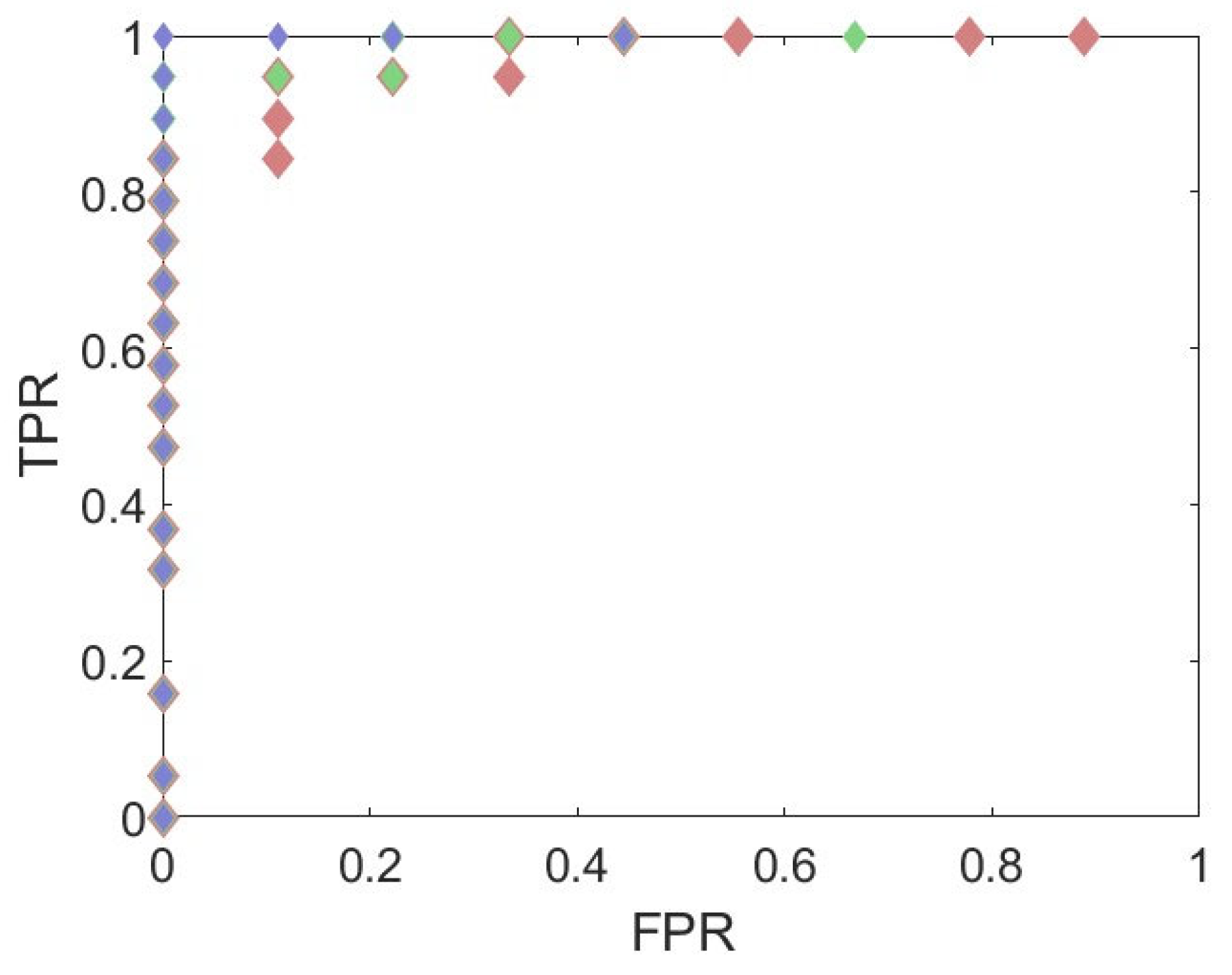
Z-axis force PSD values of a weld were lower than the corresponding threshold, then the weld has a defect and should not be used. The resulting ROC curve for this application of the thresholds are found in
Figure 13. The Go, No-Go multi-axial PSD test is 100% capable of detecting whether or not a weld is defective without false positives.
This is the first work that has related the Z-axis force to FSW defects. This finding is valuable to many manufactures who may not have the ability to measure the X-axis and Y-axis forces currently on their welding machines. In addition, these ROC plots provide the flexibility for a manufacturer to determine the best threshold for their product and the statistics best for their production. If the spatial location of the defect along the weld axis is required, or if a single part is suspect, then the use of different logic can be used. This NDE method could also be used alongside current NDE if desired.
The authors hypothesize that this NDE method may be unusable when the defect size is a significant portion of the material thickness. Thicker materials with similar defect sizes may not produce the same capability for detection. In addition, the threshold method applies to a particular tool and work piece material. However, the threshold holds true even with different parameter settings such as welding speed or machine tilt. Other force-based NDE methods, previously reviewed, required that any changes to the welding environment required additional training welds to recalibrate the system. This NDE method could be applied to other welding environments after limited in-house testing. A particular weld, with a specific tool and material, would need to be repeated to have good and bad welds. Images of this batch would be required to synthesize the second to lowest bin of spectral data to build a threshold. Once this threshold is set, a post-process NDE of a weld’s data would yield whether that weld has a defect or is defect-free. This threshold would then qualify for a similar weld that is made with the same material and tool.
