Article

Experimental and Numerical Investigations of the Deep Rolling Process to Analyze the Local Deformation Behavior of Welded Joints

by
Steffen Heikebrügge
1,*,
Bernd Breidenstein
1,
Benjamin Bergmann
1,
Christian Dänekas
2 and
Peter Schaumann
2
1
Institute of Production Engineering and Machine Tools, Leibniz University Hannover, An der Universität 2, 30823 Garbsen, Germany
2
Institute for Steel Construction, Leibniz University Hannover, ForWind, Appelstrasse 9A, 30167 Hannover, Germany
*
Author to whom correspondence should be addressed.
J. Manuf. Mater. Process. 2022, 6(3), 50; https://doi.org/10.3390/jmmp6030050
Submission received: 14 March 2022 / Revised: 6 April 2022 / Accepted: 8 April 2022 / Published: 20 April 2022

Abstract

:
Welded joints show a comparably low fatigue strength compared to the base material. Thus, different post-weld treatment methods are used to enhance the fatigue strength of welded joints. A promising method to enhance the fatigue strength of metallic components is the deep rolling process, but this has rarely been applied to welds. For the qualification of the deep rolling process as an effective post-weld treatment method, knowledge about its influence on the surface and subsurface properties at the fatigue critical weld toe is necessary. Here, geometrical and metallurgical inhomogeneities lead to complex contact states between deep rolling tools and weld toes. Thus, for a first analysis of the local deformation behavior during deep rolling of welded joints, experimentally and numerically generated deep rolling single tracks are compared. Cyclic strain-controlled tests to determine the material behavior were carried out for the numerical analyses using finite element simulation. The presented study shows that it is possible to describe the local deformation of welded joints during deep rolling using finite element simulation. A correct depiction of material behavior is crucial for such an analysis. It was shown that certain irregularities in material behavior lead to lower coincidences between simulation and experiment, especially for the investigated welds, where only low differences in hardness between base material, heat-affected zone, and filler material were found.

1. Introduction

In steel construction or mechanical engineering, many metallic structural parts are joined by a welding process. During welding with filler material, geometrical and metallurgical notches are created at the transition from weld bead to base material, called the weld toe [1]. Due to heat input during welding and subsequent cooling, shrinkage and phase transformation processes may additionally create fatigue detrimental residual stresses [2]. These circumstances mean that the fatigue resistance of welded joints is often lower than that of the base material. Lower fatigue resistance of welded joints makes it necessary to increase wall thicknesses of components and thus increases material costs. Another approach to increase the fatigue resistance of welded joints is post-weld treatment processes. In the past, different post-weld treatment processes such as tungsten inert gas welding, burr grinding, high-frequency mechanical impact treatment, or shot peening have been investigated in detail [3,4,5,6]. Most of the processes show a positive influence on the surface and subsurface properties in the weld toe leading to an increase in fatigue resistance. The processes, e.g., round the weld toe, decrease surface roughness, increase local hardness, or induce compressive residual stresses and thus lead to a pronounced increase in fatigue strength.
Another post-treatment process that combines the positive effects listed above is deep rolling. The deep rolling process is widely used in mechanical engineering to enhance the fatigue strength of different metallic components like crankshafts, wheel flanges, or axles [7]. The process is mostly used in automated process chains due to targeted adjustment of process parameters, thus making it interesting for automated manufacturing of, for example, monopiles of offshore wind turbines made of structural steel. To the authors’ knowledge, only a few detailed studies regarding the influence of deep rolling on surface and subsurface properties and the resulting fatigue resistance of welded joints are present. The studies are limited to investigations on the influence of deep rolling or burnishing on the surface and subsurface properties of tungsten inert gas welded construction steel S690QL (1.8928) [8] and stainless steel X2CrNiMo17-12-2 (1.4404) [9]. Additionally, there are investigations available on the influence of the deep rolling process on friction stir welded aluminum AlCu6Mn (EN AW-2219-T8751) [10], friction stir welded aluminum AlZnMgCu1.5 (EN AW 7075-T651) [11], and butt-welded AlMg4.5Mn0.7 (EN AW 5083) [12]. All of the investigations presented found a significant decrease in roughness, increase in hardness, and increase in compressive residual stresses. None of the articles focus on understanding the deformation principles of action during the deep rolling of welded joints and, consequently, the formation mechanisms of the addressed surface and subsurface properties.
In deep rolling, especially hydrostatic deep rolling, a ceramic ball is pressed against the workpiece surface using a medium, often common machining cooling lubricant provided by an external hydraulic unit. According to ideal Hertzian contact relations, a multiaxial stress state forms between the ball and the workpiece. The acting stress state results in elastoplastic deformations of the underlying material, which leads to deformed roughness peaks. If the ratio of acting stresses to material strength is high enough, a new formation of the workpiece surface occurs, showing an imprint of the ball and thus making it possible to predict the newly generated surface after deep rolling analytically [13,14]. Furthermore, it has been shown for several different steel materials and states that not only with sufficient acting stresses but also with an increasing number of rollovers, the geometry of generated deep rolling tracks increases in depth and width [15]. This makes it possible to describe a process-specific (depending on ball diameter and process forces) track depth by analytical equations to use the deep rolling process for material characterization when correlating the specific track depth with the material hardness.
None of the presented investigations focuses on the deformation behavior of welded joints during the deep rolling process. At welded joints, an initial inhomogeneous material state across the weld is present. Understanding the deformation behavior of the different material state sections would significantly contribute to understanding the deep rolling process applied on welded joints. For a detailed analysis of the multiaxial stress state and the resulting multiaxial strain state induced by the deep rolling process, simulations using the finite element method (FEM) have been conducted in the past [7] and are the current object of research [16,17,18]. They enable a description of the deep rolling process not often conducted before by analytical calculation of the stress state according to linear elastic Hertzian formulas, but by a more realistic subsurface stress state considering elastoplastic material behavior. The main focus of these current investigations is the correlation between the acting subsurface material stresses and the resulting material modification using FEM. Objective variables in the workpiece are, for example, the von Mises equivalent stress acting in the depth profile or the elastoplastic equivalent strain. They are correlated with the resulting maximum in-depth compressive residual stresses enabling a prediction of residual stress depth profiles by knowing the acting mechanical process loads.
For the correct numerical representation of the deep rolling process on welded joints, knowledge of the simulation settings is necessary. In the past, the process was simulated two-dimensionally (2D) and three-dimensionally (3D) in both quasi-static and explicit dynamic models, with explicit 3D models more accurately representing the generated subsurface properties [7]. For the analysis of stress states and subsurface properties, linear hexahedral mesh elements with directionally different edge lengths between 25 μm and 250 μm were used for the discretization of the subsurface of the workpieces [16,17,19]. The balls used in deep rolling consist of silicon nitride and were modeled as rigid bodies since their Young’s modulus (approx. 400 GPa) is significantly higher compared to those of the treated steel workpieces (approx. 200 GPa). Furthermore, the frictional contact was described as either frictionless or via the friction law of Coulomb with friction coefficients up to μ = 0 . 1 . The coefficients were determined from process force measurements during experiments.
A prerequisite for the correct prediction of the subsurface states is the knowledge of material behavior. Due to the high plastic deformation of the surface and subsurface during the deep rolling process, the strain hardening behavior of the workpiece material must be known. For this purpose, different material models of various metal materials were used, such as Johnson-Cook [20] or elastoplastic with isotropic hardening [21]. The elastoviscoplastic material model developed by Lemaitre and Chaboche (LC) was used most frequently [16,17,19,22]. This model combines the isotropic and non-linear kinematic hardening mechanisms that can occur in metals during repeated plastic deformation. Both hardening mechanisms can occur during the deep rolling process, too. Thus, the usage of the LC model enables relatively high coincidences between simulated and experimentally created surface and subsurface properties.
The state of knowledge shows that the deep rolling process is a promising method to enhance the fatigue strength of welded joints. Nevertheless, it has not been investigated in detail before for this use. To get a deeper understanding of the contact relations between the deep rolling ball and the fatigue critical weld toe, FE simulations are necessary since simple analytical calculations or experimental investigations are not sufficient for a description. The reasons for this are the inhomogeneous geometry at the weld toe and the inhomogeneous material state. The presented study focuses on the deformation behavior of welded joints by investigating resulting single track geometries after repeated deep rolling experimentally and numerically. First, the investigations were conducted on milled and polished welded joints to omit complex load states resulting from inhomogeneous weld toe geometry. Therefore, the focus of this study is on material behavior. The presented findings can be used as a first step into load-adapted tailoring of surface and subsurface properties of welded joints by deep rolling.

2. Materials and Methods

2.1. Preparation of Specimens

The specimens investigated in this study consist of six layers of submerged arc welded (SAW) construction steel S355G10+M (1.8813). The joining process was conducted on large sheets (2200 × 600 × 19 mm3) in an industrial environment. The filler material used for the automated welding process was S2MoTiB. The chemical composition of base material (BM) and filler material (FM), measured by optical emission spectroscopy, is depicted in Table 1.
Specimens were extracted from large welded sheets by water jet cutting. After extraction, the filler material was removed by face milling with an extensive supply of coolant to avoid influencing the subsurface properties of the welded joints. For better optical characterization of the generated single tracks, the specimens were carefully ground and polished by hand up to arithmetic mean surface roughness of Sa = 1.7 µm. A cross-section of the weld and the final specimen geometry is depicted in Figure 1.

2.2. Investigations of Material Behavior

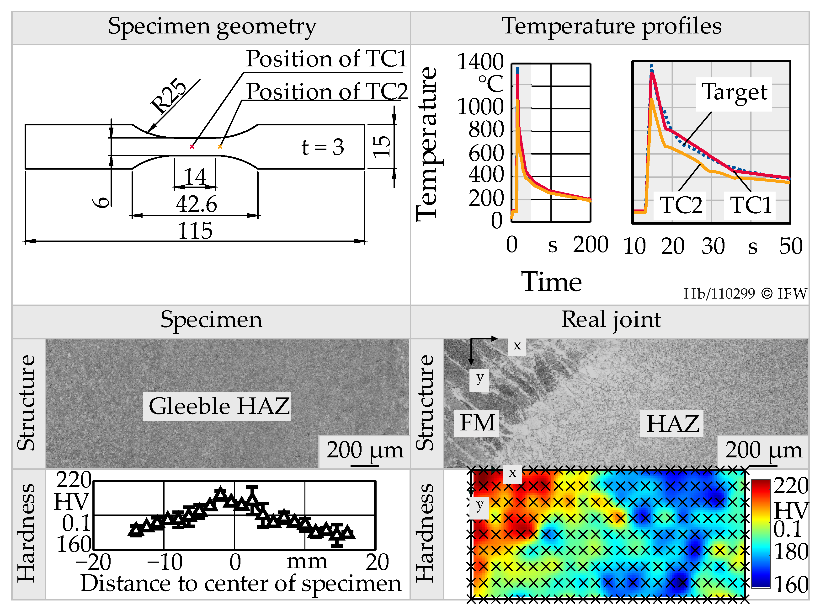
For calibration of the material model, strain-controlled material tests are necessary and were thus carried out. Because no specimens can be extracted from the heat-affected zone (HAZ), a thermomechanical simulation of the welding process is also necessary and was carried out. Thus, four specimens made of base material have been extracted from the large metal sheets, as shown in the upper left of Figure 2.
These specimens were used for a thermomechanical simulation using temperature measurements that have been conducted directly at the edge of the prepared groove during the welding of the last two layers. Temperatures were measured by K-type thermocouples during real joining processes (Target) and thermomechanical simulations (TC1, TC2). The thermomechanical simulations were conducted on a Gleeble® 3800-GTC manufactured by Dynamic Systems Inc. Measured (Target) and simulated (TC1) temperature profiles show relatively good accordance, with both having a t8/5 time (cooling time from 800 °C to 500 °C) of approx. 13.5 s. TC2 was used to receive information about the temperature gradient along the centerline of the specimen. Profiles of TC2 show lower peak temperatures, different cooling rates, and a shorter t8/5 time of approx. 10.5 s, see upper right of Figure 2.
To compare real HAZ and simulated HAZ, cross-sections of two specimens have been prepared, and hardness measurements using a Qness Q10A+ by ATM Qness GmbH have been conducted. The use of a specimen geometry with a tapered cross-section during the conductive heating of the thermomechanical simulation led to a slight gradient in hardness and microstructure along the centerline of the specimen, see bottom left of Figure 2. The gradient in hardness and microstructure is also visible in real joints, going from a hardness of 200 HV0.1 near the FM to a slightly softened area with a hardness of 160 HV0.1, see bottom right x-direction of Figure 2.
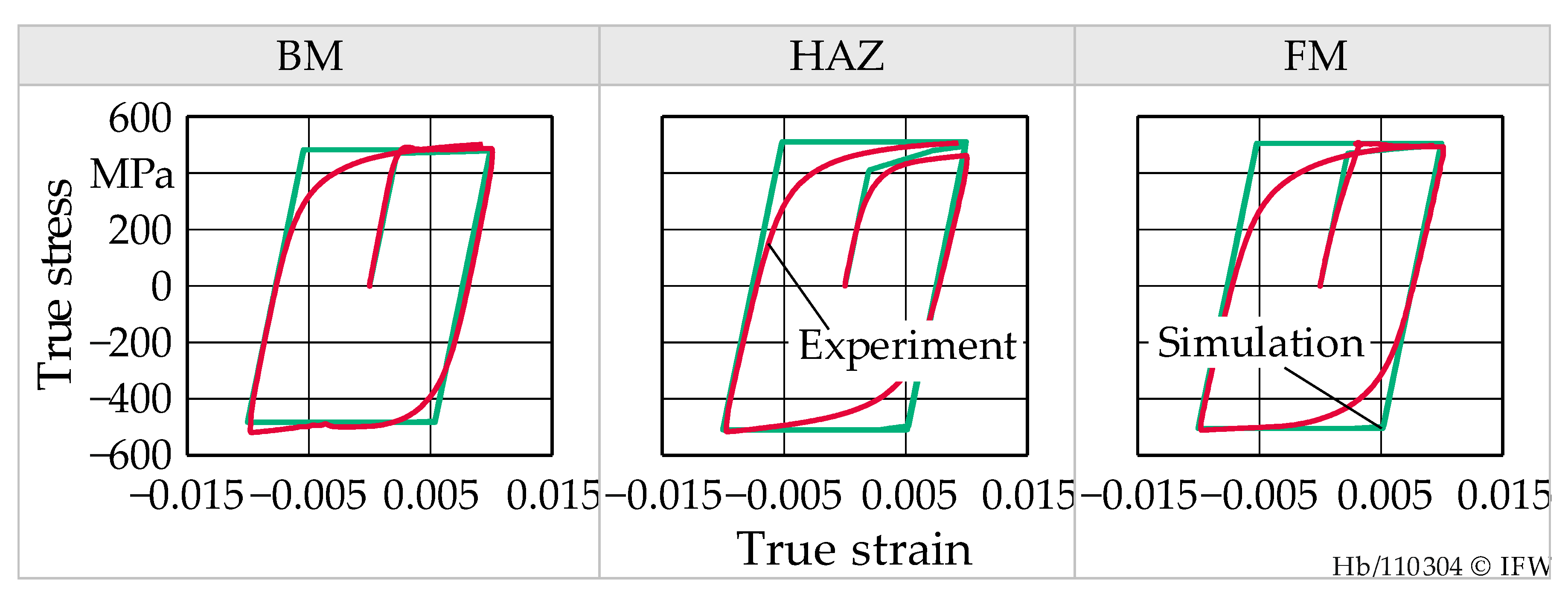
Additionally, two specimens were extracted from the filler material and the base material. Subsequently, strain-controlled material tests with a maximum strain of ε max = 1   % have been conducted with specimens extracted from BM, HAZ, and, FM. For the calibration of multilinear isotropic hardening, the first quarter cycle of the material tests was used. The calibration procedure resulted in the parameters listed in Table 2. Young’s modulus was set to E = 210 GPa and Poisson’s ratio to ν = 0 . 3 for any material state. Combinations of calibrated yield stresses σ y and plastic strains ε pl are depicted in Table 2. The parameters were validated using a single element model, see green hysteresis in Figure 3. Due to the isotropic hardening, the onset of plasticity in the negative and positive half-cycle is achieved when σ y 2 is exceeded. This leads to a slight overestimation of true stresses in simulation when the specimens in the experiment already showed yielding. Nevertheless, stress values at the minimum and maximum strain are depicted by the multilinear isotropic hardening model.

2.3. Deep Rolling of Single Tracks

To validate the numerical simulations, deep rolled single tracks were generated experimentally using hydrostatic deep rolling tools. The experiments were conducted using a Heller MC16 machine tool. Rolling pressure was provided by an external hydraulic unit using conventional machining cooling lubricant with 7% oil content. The resulting process forces were measured by a calibrated three-component dynamometer type 9257 B manufactured by Kistler Instrumente AG (Winterthur, Switzerland). For the multiple tracks, the ball diameter db, rolling pressure pr, and the number of rollovers N were varied, as shown in Table 3. Rolling velocity was set to vr = 5 m/min. For statistical validation, three tracks for each process parameter combination were generated.
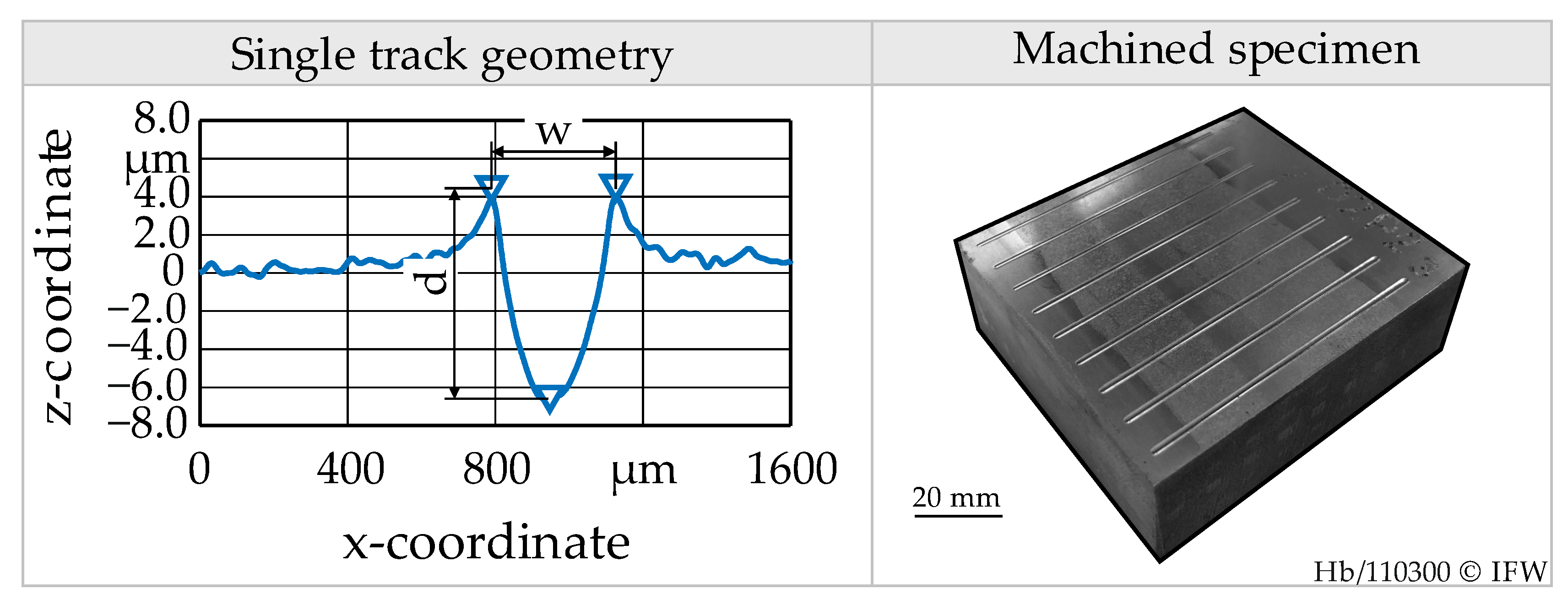
The deep rolled single tracks were characterized by the indentation width w and the indentation depth d. They were measured with the optical topography measurement system Alicona Infinite Focus G5 (Raaba, Austria). For every evaluation of the geometry parameters w and d, an area of 1600 × 1600 µm2 was measured. Afterward, five equidistant 2D profiles were extracted. Roughness and waviness were separated by a robust Gaussian filter with a cut-off wavelength of λ c = 0.05   mm . The evaluation of track geometry was performed in MATLAB R2019b by The Mathworks Inc. (Natick, MA, USA). Indentation depth was calculated by the difference between the lowest z-coordinate and mean height of the two formed peaks. The geometry of the single tracks and a machined specimen are shown in Figure 4.

2.4. Numerical Simulation

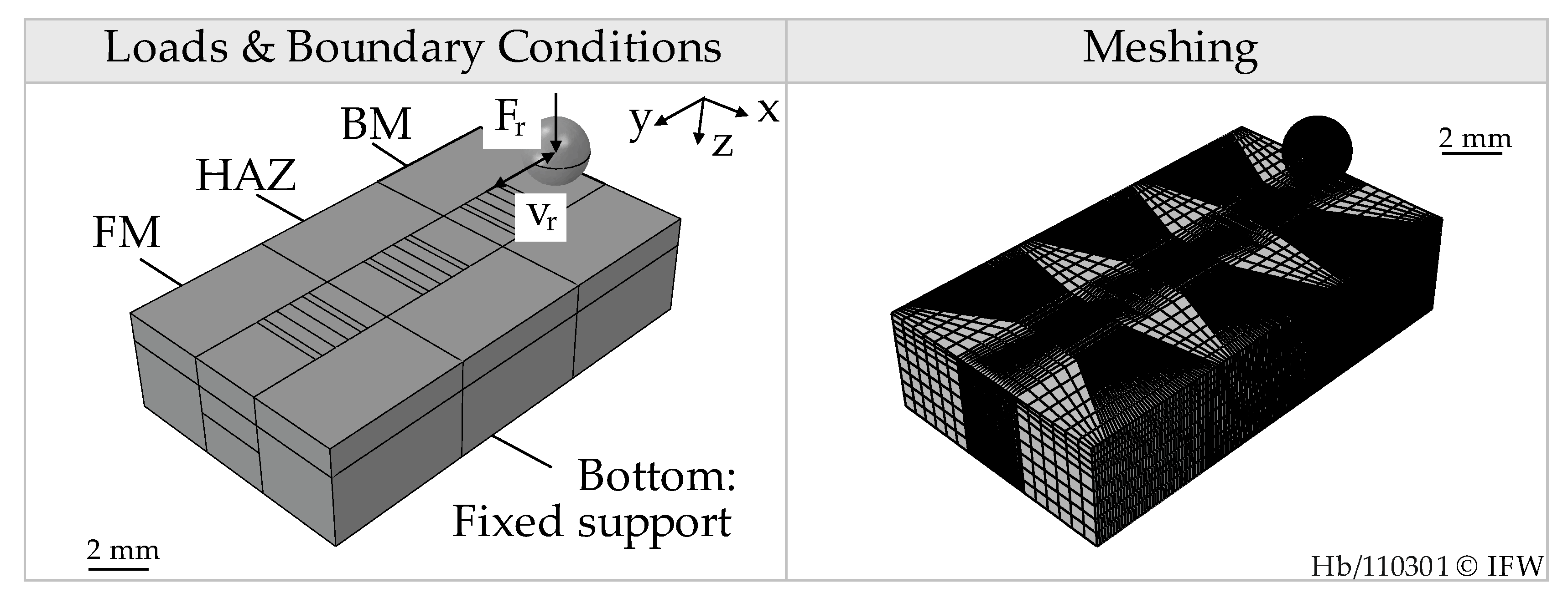
Numerical investigations were conducted using the commercial FE software package Abaqus/Explicit 2017 by Dassault Systèmes SE (Vélizy-Villacoublay, France). For simplification purposes, the specimen was modeled as a three-sectioned cuboid, see left of Figure 5. Cuboids were partitioned to achieve a finer meshing along the deep rolling tracks. At the top surface of each cuboid, additional partitions were integrated to evaluate the generated single tracks at four distinct edges. In general, the dimensions chosen were smaller than the ones of the real specimen to save computational time. Mass scaling was set to a factor of 256, likewise to save computational time. The specimen was meshed using C3D8R hexahedral elements. The ball was modeled as ideally stiff and meshed with R3D4 quadrilateral elements. The minimum edge length of the mesh of the specimen was 50 µm up to a distance from the surface of z = 1000 µm. Afterward, a progressive meshing increasing from 100 µm to 200 µm was implemented to avoid stiffness irregularities. For the first simulations, the material of the specimen was assigned using simple multilinear isotropic hardening according to Table 2 for the single zones of the welded joint.
Geometric nonlinearity was taken into account. The bottom of the specimen was assigned a fixed support. Hard contact was assigned with the ball surface as master and the workpiece surface as a slave. Friction was modeled according to Coulomb with a coefficient of μ = 0 . 1 . The coefficient was derived from process force measurements by determination of the ratio of feed force to rolling force. Isotropic elastic slip with a coefficient of γ = 0 . 005 % was chosen to take possible stick-slip behavior during the process into account and improve solution accuracy. To establish contact, a small rolling force of F r = 10   N was applied. In the subsequent step, measured process forces shown in Table 4 were applied to the ball. Afterward, the linear movement of the ball was realized with the rolling velocity of real experiments. After finishing the number of rollovers, the force was reduced to zero, and the ball lifted from the workpiece. The solution of the model was conducted at the high-performance computing cluster of the Leibniz University Hannover. For every solution, 16 cores and 128 GB of RAM were used.
The extraction of the generated track geometry was performed using a python script, and the evaluation was performed in MATLAB R2019b by The Mathworks Inc. with the same evaluation method as for the experimentally generated single tracks.

3. Results

3.1. Experimentally Determined Single Track Geometries

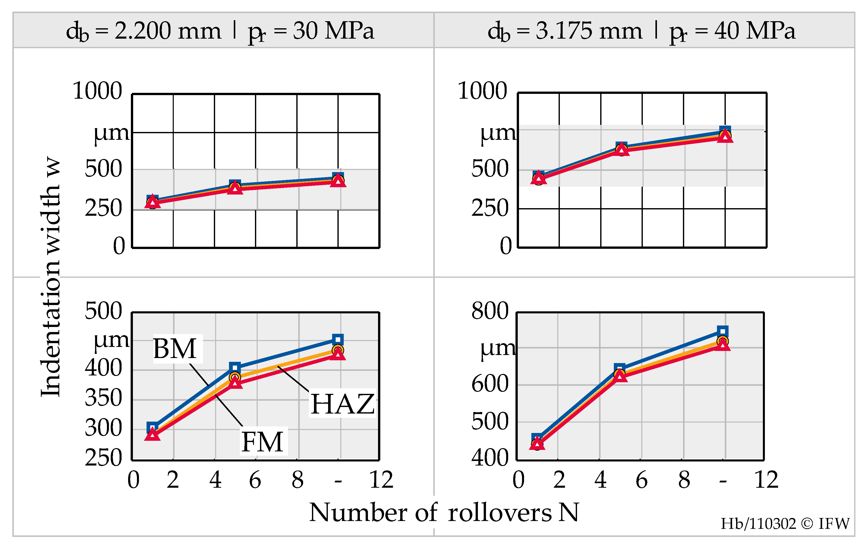
To estimate the influence of the different material regions of the welded joint on the single track geometry, the track width w was evaluated depending on the number of rollovers for two-parameter combinations, see Figure 6. The track widths are more sensitive to changes in repeated mechanical process loads, and, thus, the track depths are not presented in detail.
The results show that regardless of the acting mechanical stresses or parameter combinations used, BM has the softest material state by allowing the highest track widths already with one rollover. Track widths and depths of HAZ and FM follow in descending order. During the welding process, a thermomechanical stressing of the BM near the joining zone occurs. According to metallurgical principles, a different microstructure and thus material strength is generated in this heat-affected zone. This can also be explained by the hardness measurements seen in Figure 2, where the HAZ shows a gradient in hardness towards BM and FM being the hardest.
By repeated mechanical stressing through the deep rolling ball, hardening takes place, thus, the increase in track width and depth is finite. This hardening mechanism depends on the material state and can be characterized by the difference in track width and depth between the different numbers of rollovers. For example, for a ball diameter db = 2.200 mm, it can be seen that the increase in track width from N = 1 to N = 5 is the highest for BM, followed by HAZ and FM, varying from Δ w D 1 P 1 , BM , 1 5 = 100.9   μ m to Δ w D 1 P 1 , FM ,   1 5 = 87.6   μ m . During further processing from N = 5 to N = 10, an increase in track width is almost the same for BM, HAZ, and FM, with an average increase of Δ w D 1 , P 1 , 5 10 = 47.3   μ m and a low deviation of 1.12 µm.
For a ball diameter db = 3.175 mm, the hardening occurs differently. Here, the increase in track width from N = 1 to N = 5 is the same for the three material states, with an average of Δ w D 2 P 1 , 1 5 = 186.4   μ m and a deviation of 3.4 µm. From N = 5 to N = 10 the increase in track width is different. For BM, an increase of Δ w D 1 P 1 , BM , 1 5 = 101.8   μ m is observed, whereas the FM shows an increase of Δ w D 1 P 1 , BM , 1 5 = 85.0   μ m . The differences in increase are due to the different hardening behaviors of the different material states, which can be explained by an analysis of the mechanical load history of certain mesh nodes stressed during single track generation. Thus, an implementation of the correct hardening behavior of BM, HAZ and, FM for the numerical simulations is crucial.

3.2. Numerically Determined Single Track Geometries

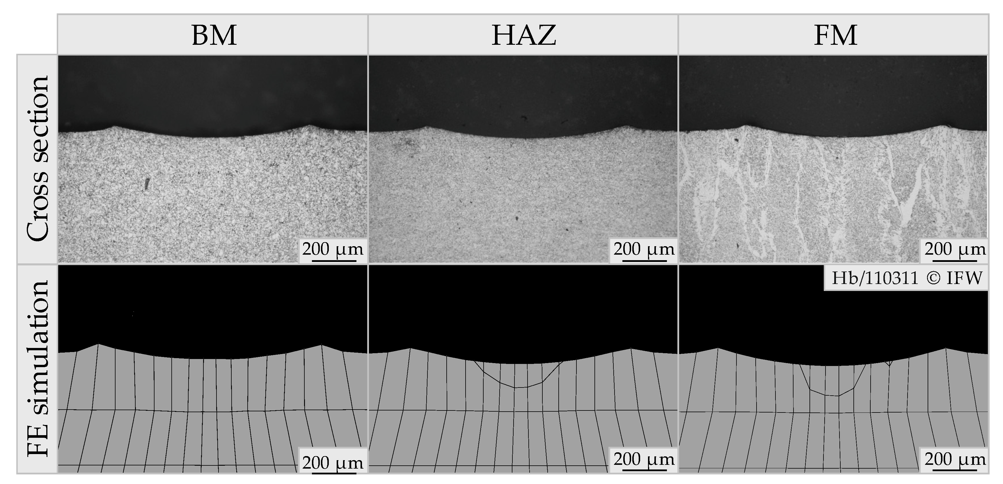
In general, the FE simulation can depict the deformation behavior of the different zones of the welded joint. This can be seen in an exemplary depiction of single track geometries obtained from cross-sections and FE simulations in Figure 7.
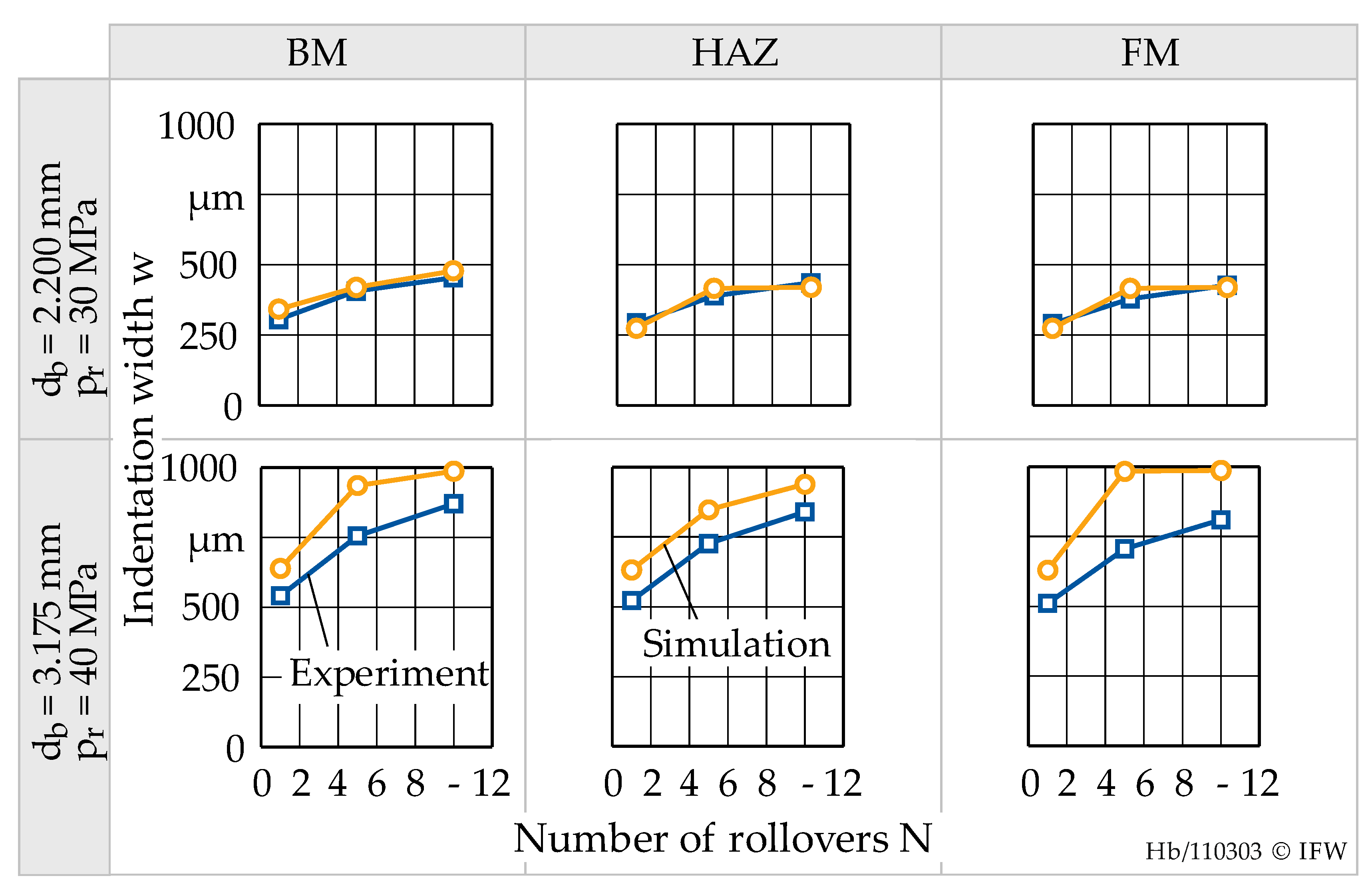
To validate the numerical process simulation and to be able to describe the deformation behavior, numerically determined single track geometries are quantitatively compared with experimentally determined geometries in Figure 8.
It is evident that the track geometries are coinciding for ball diameter db = 2.200 mm and rolling pressure pr = 30 MPa. They are overestimated in simulation for ball diameter db = 3.175 mm and rolling pressure pr = 40 MPa. The average coincidence for smaller ball diameter db = 2.200 mm throughout all simulations conducted is 94%. For ball diameter db = 3.175 mm, the average coincidence drops to a value of 79%.
There might be two reasons for lower coincidences. First, simple isotropic hardening can not describe the real hardening mechanism of the different material states. This describes the discrepancy between simulation and experiment for higher mechanical stressing, where the hardening of the material takes place more intensively. Second, the meshing of the specimens is not appropriate. During high mechanical stressing in combination with elastoplastic material behavior, a relatively high distortion of the surface near finite elements was observed. As such, it is stated, that the chosen element size of 50 µm × 50 µm is too fine for the chosen tool-process parameter combination. This is supported by the findings from finite element simulations of, for example, shot peening. Here, recommendations for the ratio of the surface mesh size to experimentally determined indentation diameter were developed. They vary from 1:10 to 1:20 [23]. In the presented FE deep rolling process simulations, the ratio is 1:9 for db = 2.200 mm or 1:17 for db = 3.175 mm. A coarser mesh might lead to a more precise depiction of the generated single-track geometries.

4. Discussion

In the investigations presented, the deep rolling process was used to describe the local deformation behavior of welded joints for the first time. Experimental investigations of the deep rolling process have shown that for the investigated welds, differences in deformation behavior between base material, the heat-affected zone, and filler material can be detected. Furthermore, their hardening behavior, meaning the difference in the increase in track geometry for an increasing number of rollovers, is different. These findings complement the study of Wielki et al. [15]. They found that the deep rolling process can be used to describe the deformation or hardening behavior of different Fe-based steels (from 158 to 833 HV1), allowing a specific track depth to be calculated depending on the used deep rolling tool diameter db and pressure pr. This specific track depth depends on the chosen material hardness, where a higher hardness leads to a lower specific track depth. This enables the deep rolling process to be used as a suitable descriptor for the material properties of the machined workpiece. Regarding the investigated welded joint, the gradient in hardness across the joint (from 160–220 HV0.1) is not as high as the range of material hardness investigated by Wielki et al. Thus, the differences in track geometries between the material states are comparably smaller but can be detected.
Regarding the simulations conducted, the coincidences with the experimental results are lower for higher rolling pressure and bigger ball diameter. This is due to the relatively high distortion of finite elements. Nevertheless, for lower rolling pressures, the coincidences with experimental results are comparably high. This is already achieved by using a multilinear isotropic hardening model. The necessity of a thermophysical simulation of the heat-affected zone for finite element simulation of deep rolling of welds was shown. For the heat-affected zone, the derived material properties are plausible due to the comparably high t8/5 times leading to a softened heat-affected zone that can also be seen in hardness measurements. This coincides with the state of the art for the derivation of welded joint material properties [1]. Schubnell et al. show that comparably low t8/5 times of approx. 4 s during thermomechanical simulation lead to coarser grains and higher material hardness or strength than the base material of different structural steel grades. This is also following time-temperature transformation relationships known from the metallurgy. This explains that simulated heat-affected zones in the study presented with t8/5 times of approx. 13.5 s show partly lower material strengths than the base material.
In the past, no numerical investigations of the deep rolling process for an application on welded joints have been conducted. Most of the numerical investigations regarding welded joints focus on high-frequency mechanical impact treatment (HFMI) [24,25]. Here it is shown that for a prediction of surface and subsurface properties of welds after treatment, it is mandatory to implement the correct material behavior of the different material states found across the welded joint. This will also be necessary for numerical simulations of the deep rolling process applied to welded joints. Here, new relationships between acting mechanical process loads, the deformation behavior of the complex-shaped weld toe, and the resulting surface and subsurface properties can be derived.

5. Conclusions

From the investigations presented, the following conclusions can be drawn:
Different material states across the welded joint show different material properties and hardening behavior that can be characterized by the deep rolling process
An implementation of the different material properties must be used for a numerical simulation of the deep rolling process on welded joints, with a validation directly depending on the quality of the results from material investigations
Simple multilinear isotropic hardening is not sufficient, but able to describe the yield and hardening behavior during multiple deep rolling
Future research will be conducted on a detailed depiction of the correct material properties. This includes the derivation of Lemaitre Chaboche or Mechanical Threshold Stress model parameters from strain-controlled Incremental Step Tests and Constant Amplitude Tests. This will be used to describe the complex stress state acting during the deep rolling of the weld toe by simulating the process applied to real weld geometries. This is mandatory to link the functional fatigue performance of the welded joints, which will be quantified by fatigue tests, with the acting mechanical process loads during the deep rolling process, the resulting weld toe geometry, and the induced surface and subsurface properties.

Author Contributions

Conceptualization, S.H.; methodology, S.H.; software, S.H.; validation, S.H.; formal analysis, S.H.; investigation, S.H.; resources, S.H. and C.D.; data curation, S.H.; writing—original draft preparation, S.H.; writing—review and editing, S.H., B.B. (Bernd Breidenstein), B.B. (Benjamin Bergmann), C.D. and P.S.; visualization, S.H.; supervision, B.B. (Bernd Breidenstein), B.B. (Benjamin Bergmann), P.S.; project administration, B.B. (Bernd Breidenstein), B.B. (Benjamin Bergmann) and P.S.; funding acquisition, S.H., B.B. (Bernd Breidenstein), B.B. (Benjamin Bergmann), C.D. and P.S. All authors have read and agreed to the published version of the manuscript.

Funding

This research was funded by the German Federation of Industrial Research Assosciations (AiF), grant numbers 20626/N and 21496/N and the “Sieglinde Vollmer Stiftung”.

Data Availability Statement

Data from the study presented can be received from the corresponding author upon request.

Acknowledgments

The authors thank the German Federation of Industrial Research Associations (AiF) for the financial support of the project “Deep rolled welds—Increased fatigue strength of welded joints in wind energy by deep rolling”, grant number 20626/N, and the project “Fatigue strength of butt joints of high-strength fine-grained offshore construction steels with and without post-treatment for the construction of offshore wind turbines”, grant number 21496/N. Both projects are part of the program for promoting industrial cooperative research (IGF) based on a decision by the German Bundestag. The projects were initiated and are organized by the Research Association for Steel Application (FOSTA). Additionally, the authors would like to thank the “Sieglinde Vollmer Stiftung” for the financial support of this research work.

Conflicts of Interest

The authors declare no conflict of interest.

References

  1. Schubnell, J.; Discher, D.; Farajian, M. Determination of the static, dynamic and cyclic properties of the heat affected zone for different steel grades. Mater. Test. 2019, 61, 635–642. [Google Scholar] [CrossRef]
  2. Zinn, W.; Scholtes, B. Residual stress formation processess during welding and joining. In Handbook of Residual Stress and Deformation of Steel, First Print; Totten, G.E., Howes, M.A.H., Inoue, T., Eds.; ASM International: Novelty, OH, USA, 2002; pp. 391–396. [Google Scholar]
  3. Harati, E.; Svensson, L.-E.; Karlsson, L.; Hurtig, K. Effect of HFMI treatment procedure on weld toe geometry and fatigue properties of high strength steel welds. Procedia Struct. Integr. 2016, 2, 3483–3490. [Google Scholar] [CrossRef] [Green Version]
  4. Hensel, J.; Eslami, H.; Nitschke-Pagel, T.; Dilger, K. Fatigue Strength Enhancement of Butt Welds by Means of Shot Peening and Clean Blasting. Metals 2019, 9, 744. [Google Scholar] [CrossRef] [Green Version]
  5. Pedersen, M.M.; Mouritsen, O.Ø.; Hansen, M.R.; Andersen, J.G.; Wenderby, J. Comparison of Post-Weld Treatment of High-Strength Steel Welded Joints in Medium Cycle Fatigue. Weld. World 2010, 54, 208–217. [Google Scholar] [CrossRef] [Green Version]
  6. Lieurade, H.; Huther, I.; Lefebvre, F. Effect of weld quality and postweld improvement techniques on the fatigue resistance of extra high strength steels. Weld. World 2008, 52, 106–115. [Google Scholar] [CrossRef]
  7. Delgado, P.; Cuesta, I.I.; Alegre, J.M.; Díaz, A. State of the art of Deep Rolling. Precis. Eng. 2016, 46, 1–10. [Google Scholar] [CrossRef]
  8. Farajian, M.; Barsoum, Z.; Kromm, A. Residual Stress Engineering in Fatigue Resistant Welds. Mater. Sci. Forum 2013, 768–769, 613–619. [Google Scholar] [CrossRef]
  9. Thanakulwattana, W.; Nakkiew, W. Residual Stress Analysis in Deep Rolling Process on Gas Tungsten Arc Weld of Stainless Steel AISI 316L. Key Eng. Mater. 2021, 880, 23–28. [Google Scholar] [CrossRef]
  10. Prevéy, P.; Mahoney, M.W. Improved Fatigue Performance of Friction Stir Welds with Low Plasticity Burnishing: Residual Stress Design and Fatigue Performance Assessment. Mater. Sci. Forum 2003, 426–432, 2933–2940. [Google Scholar] [CrossRef]
  11. Baisukhan, A.; Nakkiew, W. Sequential Effects of Deep Rolling and Post-Weld Heat Treatment on Surface Integrity of AA7075-T651 Aluminum Alloy Friction Stir Welding. Materials 2019, 12, 3510. [Google Scholar] [CrossRef] [Green Version]
  12. Schubnell, J.; Farajian, M. Fatigue improvement of aluminium welds by means of deep rolling and diamond burnishing. Weld. World 2021, 66, 699–708. [Google Scholar] [CrossRef]
  13. Denkena, B.; Krödel, A.; Heikebrügge, S.; Meyer, K.; Pillkahn, P. Surface topography after deep rolling with milling kinematics. Prod. Eng. 2021, 15, 587–593. [Google Scholar] [CrossRef]
  14. Denkena, B.; Abrão, A.; Krödel, A.; Meyer, K. Analytic roughness prediction by deep rolling. Prod. Eng. 2020, 14, 345–354. [Google Scholar] [CrossRef]
  15. Wielki, N.; Heinz, N.; Meyer, D. Characterizing the Local Material Properties of Different Fe-C-Cr-steels by Using Deep Rolled Single Tracks. Materials 2020, 13, 4987. [Google Scholar] [CrossRef] [PubMed]
  16. Kinner-Becker, T.; Sölter, J.; Karpuschewski, B. A simulation-based analysis of internal material loads and material modifications in multi-step deep rolling. Procedia CIRP 2020, 87, 515–520. [Google Scholar] [CrossRef]
  17. Kinner-Becker, T.; Hettig, M.; Sölter, J.; Meyer, D. Analysis of internal material loads and Process Signature Components in deep rolling. J. Manuf. Sci. Technol. 2021, 35, 400–409. [Google Scholar] [CrossRef]
  18. Kuschel, S.; Kinner-Becker, T.; Zmich, R.; Sölter, J.; Meyer, D. Modelling and Simulation of Mechanical Loads and Residual Stresses in Deep Rolling at Elevated Temperature. J. Manuf. Mater. Processing 2021, 5, 76. [Google Scholar] [CrossRef]
  19. Lyubenova, N.; Baehre, D. Finite Element Modelling and Investigation of the Process Parameters in Deep Rolling of AISI 4140 Steel. J. Mater. Sci. Eng. B 2015, 5, 277–287. [Google Scholar] [CrossRef] [Green Version]
  20. Majzoobi, G.H.; Teimoorial Motlagh, S.; Amiri, A. Numerical simulation of residual stress induced by roll-peening. Trans. Indian Inst. Met. 2010, 63, 499–504. [Google Scholar] [CrossRef]
  21. Lim, A.; Castagne, S.; Wong, C.C. Quasi-static Process Modelling of Deep Cold Rolling on Ti-6Al-4V. Mater. Res. Proc. 2016, 2, 7–12. [Google Scholar] [CrossRef] [Green Version]
  22. Trauth, D.; Klocke, F.; Mattfeld, P.; Klink, A. Time-efficient Prediction of the Surface Layer State after Deep Rolling using Similarity Mechanics Approach. Procedia CIRP 2013, 9, 29–34. [Google Scholar] [CrossRef] [Green Version]
  23. Bagherifard, S.; Ghelichi, R.; Guagliano, M. A numerical model of severe shot peening (SSP) to predict the generation of a nanostructured surface layer of material. Surf. Coat. Technol. 2010, 204, 4081–4090. [Google Scholar] [CrossRef]
  24. Foehrenbach, J.; Hardenacke, V.; Farajian, M. High frequency mechanical impact treatment (HFMI) for the fatigue improvement: Numerical and experimental investigations to describe the condition in the surface layer. Weld. World 2016, 60, 749–755. [Google Scholar] [CrossRef]
  25. Ernould, C.; Schubnell, J.; Farajian, M.; Maciolek, A.; Simunek, D.; Leitner, M.; Stoschka, M. Application of different simulation approaches to numerically optimize high-frequency mechanical impact (HFMI) post-treatment process. Weld. World 2019, 63, 725–738. [Google Scholar] [CrossRef]
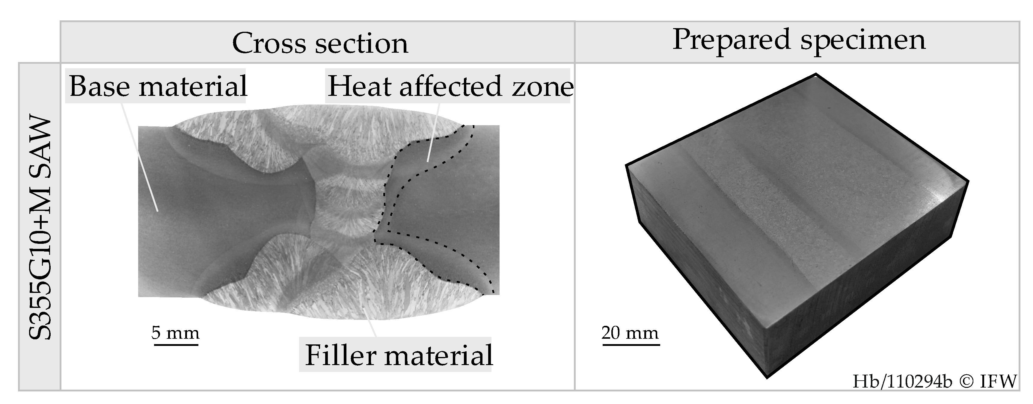
Figure 1. Cross-section of weld and specimen geometry.
Jmmp 06 00050 g001
Figure 2. Specimen geometry, thermomechanical simulation, and comparison of hardness and microstructure.
Jmmp 06 00050 g002
Figure 3. Comparison of stress-strain hysteresis for multilinear isotropic hardening models.
Jmmp 06 00050 g003
Figure 4. Single-track geometry and machined specimen.
Jmmp 06 00050 g004
Figure 5. Loads, boundary conditions, and meshing of deep rolling FE-model.
Jmmp 06 00050 g005
Figure 6. Evaluation of experimentally determined track widths for two parameter combinations.
Jmmp 06 00050 g006
Figure 7. Comparison of experimentally and numerically determined single track geometries for d b = 3.175   mm , p r = 40   MPa and N = 10.
Jmmp 06 00050 g007
Figure 8. Comparison of experimentally and numerically determined indentation widths for two different parameter combinations.
Jmmp 06 00050 g008
Table 1. Chemical composition of base material and filler material.
MaterialElement 1CAlSiCrMnCoNiNbWBTiCuMo
S355G10+MWt. %0.050.030.360.361.340.020.030.040.02----
S2MoTiBWt. %0.05-0.430.071.55-0.18--0.010.140.050.19
1 Fe balanced.
Table 2. Calibrated isotropic hardening parameters of the multilinear model.
Material StateYield Stress σ y 0 σ y 1 σ y 2 Plastic Strain ε pl 0 ε pl 1 ε pl 2
BMMPa470475483%00.51.0
HAZ410480510
FM470490505
Table 3. Process parameters used in experimental investigations.
Ball Diameter db [mm]Rolling Pressure pr [MPa]Number of Rollovers N [-]
2.2000; 3.17530; 401; 5; 10
Table 4. Experimentally measured process forces F r [N] used in the simulation.
Rolling Pressure pr [MPa]Ball Diameter db [mm]
2.2003.175
3063.583.3
40173.2231.4
Publisher’s Note: MDPI stays neutral with regard to jurisdictional claims in published maps and institutional affiliations.