Article

Improvement of Cooling Effect and Dimensional Accuracy of Wire and Arc Additive Manufactured Magnesium Alloy by Active-Cooling-Based Contacting Copper Blocks

by
Hideaki Nagamatsu
* and
Hiroyuki Sasahara
Department of Mechanical Systems Engineering, Tokyo University of Agriculture and Technology, 2-24-16 Naka-cho, Koganei-shi, Tokyo 184-8588, Japan
*
Author to whom correspondence should be addressed.
J. Manuf. Mater. Process. 2022, 6(2), 27; https://doi.org/10.3390/jmmp6020027
Submission received: 18 January 2022 / Revised: 17 February 2022 / Accepted: 18 February 2022 / Published: 24 February 2022
(This article belongs to the Topic Additive Manufacturing)

Abstract

:
Wire and arc additive manufacturing (WAAM) employing a magnesium (Mg) alloy is superior in terms of safety, energy efficiency, and deposition rate when compared with a process that utilizes lasers and powder materials. However, problems with WAAM employing an Mg alloy include poor dimensional accuracy due to low viscosity of the molten Mg alloy. In addition, since Mg alloys cause a combustion reaction with water, an effective cooling method, such as direct water cooling, cannot be applied. In this study, a solid contact-based active cooling method employing copper blocks with high thermal conductivity was proposed to improve the dimensional accuracy and cooling efficiency of fabricated objects using AZ31. Moreover, the proposed method renders it possible to fabricate a wall structure with high flatness as the molten AZ31 solidifies upon direct contact with the flat surface of copper blocks. In addition, the copper blocks harboring an internal water circulation system achieved a higher cooling efficiency and shortened the interval cooling time between the deposition of subsequent layers. Meanwhile, it was discovered that the arc deflected toward the copper blocks, not onto the substrate or the previous layer when the wire tip approached too close to the blocks.

1. Introduction

In recent years, industrial fields such as aerospace and automotive industries have required improvements in the fuel efficiency of transportation equipment and reductions in product weight in terms of both materials and manufacturing technology. Regarding materials, lightweight materials are widely used to replace denser materials [1,2]. In particular, magnesium (Mg) alloys possess great advantages, such as being the lightest metal material employed in manufacturing, as well as high specific strength and stiffness [3]. Regarding manufacturing technology, product weight can be reduced by additive manufacturing (AM), an advanced free-form fabrication technology, relative to the weight of products produced with conventional technology. Therefore, the development of Mg alloy products using AM has attracted attention within a wide range of industrial fields and has been demonstrated using powder bed fusion (PBF [4]), directed energy deposition (DED [5]), binder jetting [6], and friction surfacing [7]. However, most laser energy is reflected due to the low absorption of Mg [8], thus an AM process employing a laser as a heat source bears poor energy efficiency and entails the risk of equipment failure. In addition, handling fine Mg powder with great care is crucial owing to its flammable and explosive properties.
Wire and arc AM (WAAM) technology uses a welding arc as a heat source, which is much more energy efficient and exhibits a much higher deposition rate than laser-based DED, and welding wire as the filler metal, which is regarded much safer than PBF. Hence, WAAM provides a suitable AM technique for fabricating Mg alloys. Previous researchers who had investigated WAAM of Mg alloys used tungsten inert gas (TIG) or metal inert gas (MIG) as welding power sources reported the effects of different kinds of welding power sources and welding parameters on the bead shape, mechanical properties, and metallography of fabricated Mg alloy structures [9,10,11,12,13,14,15,16]. However, WAAM using an Mg alloy exhibits a lower dimensional accuracy compared with other materials or to AM technology due to the physical properties of Mg and the heat-input process of WAAM. Mg exhibits a low melting point and low surface tension, thus molten Mg bears low viscosity. Compared to aluminum (Al), Mg contains a similar melting point, 0.6 times the thermal conductivity, 0.7 times the specific heat, and 1.7 times the electrical resistance, meaning that the molten volume of Mg is twice that of Al for the same input heat [17]. Therefore, an Mg alloy bead contains a large amount of welded metal parts and a tendency toward a shallow penetration depth. In addition, WAAM objects tend to become hotter than objects produced by other AM methods, and the dimensional accuracy of the fabricated objects tends to decrease. This is due to higher thermal energy deposited into the molten material and a larger amount of material deposited per layer in WAAM compared with other AM methods. Thus, the dimensional accuracy of WAAM with an Mg alloy tends to deteriorate compared with other materials or AM methods. However, few previous studies have focused on improving the dimensional accuracy of WAAM employing an Mg alloy.
The solidification speed of molten metal bears a great influence on the dimensional accuracy of WAAM-fabricated objects, and it is known that their thermal management is important. Figure 1 schematically illustrates the general types of cooling strategies to improve the dimensional accuracy and thermal diffusion of WAAM objects. Figure 1a illustrates free convection cooling (FCC). FCC represents the simplest and most referenced approach, in which the object is cooled by the atmosphere during an appropriate interpass cooling time known as the dwell time. Heat in the fabricated objects is transferred and radiated to the atmosphere, and then is conducted to a substrate with large heat capacity [18,19]. However, the thermal performance of this method is low, and in order to sufficiently lower the interpass temperature, the dwell time must be extended, resulting in the prolongation of the whole fabrication process regardless of WAAM achieving a high deposition rate.
Figure 1b shows an active cooling method using air jets, or highly pressurized air which is sprayed onto the fabricated object to remove laminar flow, thus achieving a greater cooling effect and shorter dwell time than FCC [20,21,22]. William et al. [20] applied active-air cooling to the WAAM process using carbon steel and reported that it suppressed the gradual increase in interpass temperature compared to FCC. However, they also reported a limit to the effectiveness of this cooling strategy by convective heat transfer.
Figure 1c displays a method of direct water cooling using a water bath. In this method, a WAAM object is fabricated in a water bath and the interpass temperature is controlled by raising the water level depending on the height of the object so as to maintain a constant distance between the fabrication point and the water surface. Since the heat transfer to the water is much higher than that to the air, the object can be cooled more effectively [23,24,25,26]. Uwe R et al. [24] applied four cooling methods—natural air cooling, air jet cooling, aerosol cooling, and water cooling—to the WAAM process using steel materials and found that water cooling proved the most effective method. With direct water cooling, however, a fabricated object may be prone to hydrogen or oxygen contamination. In particular, it is impossible to apply direct water cooling to the WAAM with Mg alloy since Mg in a high-temperature state may explode or severely combust upon contact with water. Thus, these cooling strategies bear their own merits and demerits, and no innovative method has been established yet to improve both the dimensional accuracy and efficiency of the whole fabrication process of WAAM using an Mg alloy.
Therefore, we focused on the active cooling method shown in Figure 1d, which improves the dimensional accuracy and heat dissipation of WAAM by contacting the solid structures with the molten metal [27,28]. Direct contact of a solid bearing a high thermal conductivity with molten Mg alloy is expected to provide a strong cooling effect and dimensional accuracy to fabricated Mg alloy objects while avoiding combustion. Fang L et al. [27] improved the cooling effect and dimensional accuracy of WAAM-wall structures using an Al alloy and employing the developed heat transportation structure based on the thermoelectric cooling technique. Zhang A et al. [28] used pure copper plates with high thermal conductivity as a heat transportation object and observed that the copper plates could minimize hydrogen pores and improve the ultimate tensile strength of the WAAM wall structure of Al alloys. However, these previous studies investigated the cooling effect only on Al alloys, not Mg alloys. In addition, the influence of processing parameters on the cooling performance of the used heat transportation object has not been observed. In particular, it is expected that a sequential arc discharge or high input heat decreases the cooling performance of the heat transportation object. Furthermore, the heat transportation objects comprised of pure copper with a high electrical conductivity can cause arc deflection and an irregular bead geometry, but these concerns have not been discussed.
In this study, a Solid Contact-based Active Cooling system using pure copper blocks (SCAC) is proposed to improve the dimensional accuracy and the cooling effect of the WAAM wall structure using an Mg alloy. The wall structure of the Mg alloy is fabricated by depositing molten metal into a gap between the two copper blocks fixed on both sides of the fabrication path. Pure copper, with its high thermal conductivity, is suitable as a backing plate to increase the cooling rate of the Mg alloy [29,30]. In addition, SCAC with an internal water circulation (SCACW) is developed to further improve the cooling effect. Water-cooling copper can restrain the molten pool without melting of the copper even in an electrogas arc welding process under extremely high input heat conditions [31]. Thus, the purpose of this study is to investigate the influences of the proposed active cooling methods—SCAC and SCACW—on the dimensional accuracy and cooling effect of a WAAM wall structure of Mg alloy. Section 3 describes the experimental results and discussion of this paper and is organized as follows: Section 3.1 evaluates the influence of the arc length and the positional relationship between the wire tip and the copper blocks on the arc deflection, bead formation, and penetration. Section 3.2 presents the temperature state of the fabricated walls of Mg alloy and the used copper blocks during FCC, SCAC, and SCACW. Finally, the effect of the fabrication parameters and the proposed cooling methods on the dimensional accuracy of the fabricated walls of Mg alloy are provided in Section 3.3.

2. Materials and Methods

2.1. Materials Used

The component values of the wire material are shown in Table 1. The substrate and wire are both an Mg alloy equivalent to AZ31, and the dimensions of the substrate measure 150   mm   ×   40   mm   ×   5   mm.
The physical properties of the copper blocks adapted as the heat transportation structures are shown in Table 2. The copper blocks used are equivalent to JIS standard C1100P. Figure 2 displays three kinds of copper blocks with different dimensions designated as types A, B, and C. The dimensions of the types A, B, and C measure 200   mm   ×   15   mm   ×   10   mm , 200   mm   ×   15   mm   ×   15   mm , and 200   mm   ×   22   mm   ×   22   mm with a long hole of Φ 14.5 mm, respectively. Type A was employed for the fabrication process from the first several layers, while types B and C were used for SCAC and SCACW, respectively. The details of these applications are discussed in Section 2.3.

2.2. WAAM System

The schematic and actual appearance of the WAAM system used are shown in Figure 3. By manually raising the mini jacks located at both ends of the apparatus, the positions of the two copper blocks can be adjusted along the Z-axis, so that the molten Mg alloy maintains constant contact with the copper blocks according to the height of the fabricated wall. In addition, the two spacers fixed by the copper blocks provided a uniform width space. The width of the space between the copper blocks (W) was adjusted by exchanging the spacers.
An MIG welder (WB-P500L, DAIHEN Corporation, Osaka, Japan) provided the power source. The WAAM system consists of three orthogonal axes, and the trajectory of the welding torch (BTA300-30, DAIHEN Corporation, Osaka, Japan) attached to the Z-axis plate is controlled by a computer numerical control (CNC) system. In MIG welding, the curved wire, which plays the role of the electrode, is fed from the contact tube. The curvature of the wire tip increases in proportion to the contact tube to work distance (CTWD) [32]. Therefore, W and CTWD are important parameters in determining the positional relationship between the wire tip and the copper blocks.
Type C was connected to an external water tank through a water pipe adapter and hose as shown in Figure 4. Cooling water equivalent to room temperature (about 12 °C) remained in constant circulation inside the copper blocks via an electric pump. The volume flow rate and the flow velocity of cooling water were 3 × 10 4   m 3 / s and 1 . 9   m / s , respectively.

2.3. Fabrication Process

In SCAC or SCACW, CTWD must be controlled to within 16   ±   2 . 5 mm to prevent discharging the arc to the copper block (the relationship between CTWD and arc deflection is explained in detail in Section 3.1), and the fabricated wall must bear a uniform fabrication height. In general, the molten metal deposited at the end tends to hang down and the height of the fabricated object tends to be nonuniform between the center and the end in the WAAM process due to the lower thermal diffusivity of the end portion compared to the center portion [11,33]. Figure 5a displays the travel direction. In this study, a bead with 5 mm length from the end was fabricated first, followed by fabrication of a bead with 75 mm length from the opposite side. As shown in Figure 5b, when one end of the part was partially formed with a lower height, additional fabrication was performed on the part. Furthermore, the fabrication height was rendered uniform by reversing the torch travel direction for each odd- and even-numbered layer.
Figure 6 shows a schematic diagram of the application and the timing of the replacement of the copper blocks. The height of the copper block applied to the first layer must be lower than the torch tip to the substrate distance. The available range of CTWD is 16   ±   2 . 5 mm, and the contact tube setback is 6 mm as shown in Figure 3b. Therefore, type A copper blocks with a 10 mm height were employed in the fabrication from one to several layers; this height was sufficient to apply type B with a 15 mm height and type C with a 22 mm height, as shown in Figure 6a. After several layers were fabricated, the walls were cooled to below 30 °C by free convection, as illustrated in Figure 6b. Following this, type A was exchanged for type B or type C and fabrication restarted, as shown in Figure 6c. The dimensional accuracy and temperature of the fabricated walls refer to the fabrication process using type B or C.

2.4. Processing Parameters

Table 3 displays the common processing parameters. The deposition rate measured 774 cm3/h, which is very high compared to other AM fabrication cases.
Table 4 shows the individual processing parameters of all fabrication experiments conducted in this study. Test No. 0 refers to all parameters of a single bead or wall structures fabrication experiment. In this experiment, the influence of CTWD, W, and the average output voltage (U) on arc deflection, bead formation, and bead penetration was investigated. Numbers 1 to 16 refer to the test numbers of the fabricated-wall structures to observe the effect of the proposed cooling methods and fabrication parameters on the cooling effect and dimensional accuracy of the fabricated wall. In this experiment, W, travel speed (TS), and dwell time (t) were focused on.

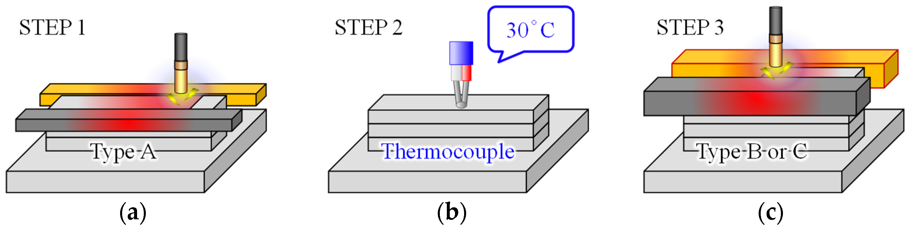
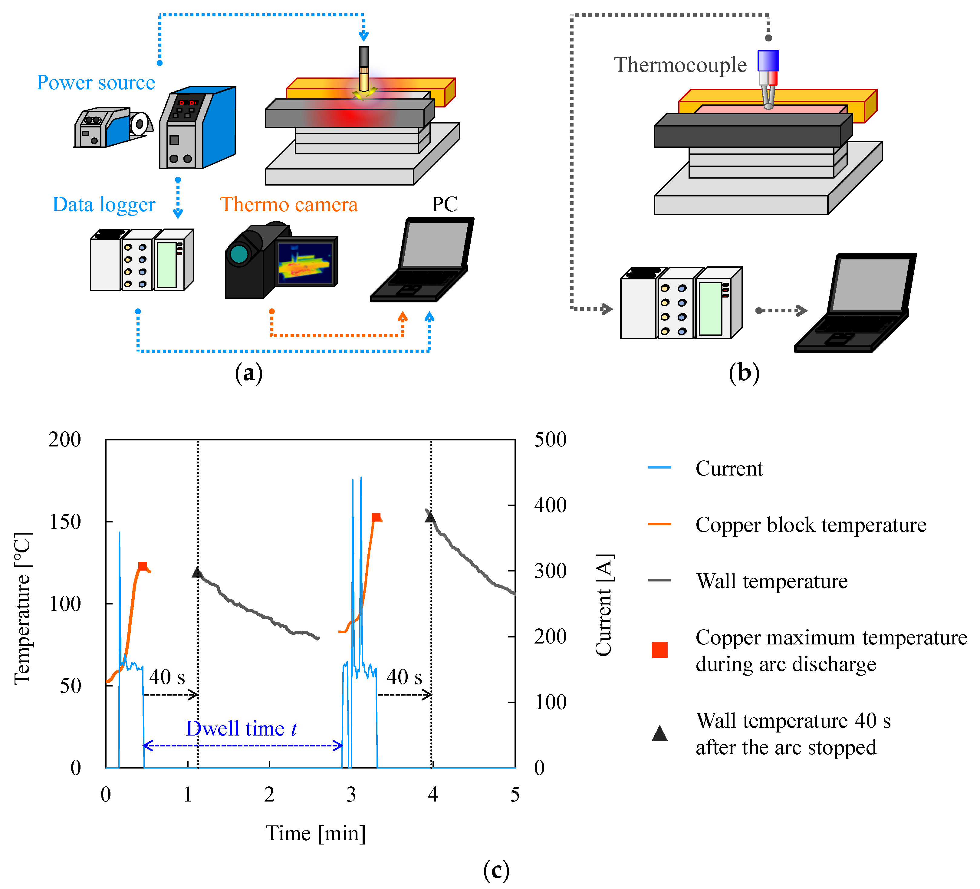
2.5. Measurement and Evaluation of Temperature History of Fabricated Walls and Copper Blocks

To verify the cooling effect of this method on the fabricated walls, (i) the temperature of the copper block during arc discharge and (ii) the interpass temperature of the top surface of the fabricated walls were measured. A schematic diagram of the measurement setup for (i) and (ii) are shown in Figure 7a,b, respectively. Figure 7c illustrates an example of the measurement history regarding the current and temperature of the copper block and the fabricated wall. In the case of (i), the maximum temperature of the copper block was measured with a thermal imaging camera (T630sc, Teledyne FLIR LLC, Wilsonville, OR, USA). The emissivity was set as 0.94 since the copper blocks were coated with a black body spray with 0.94 emissivity prior to the experiment as shown in Figure 3a and Figure 4a. The center of the side surface of the copper block represented the sampling area. In the case of (ii), the interpass temperature history of the fabricated walls was measured with a K-type thermocouple (TH-8292-2, Three High Corp., Ltd., Kanagawa, Japan), and not a non-contact form of measurement. This was performed since a WAAM-fabricated object using AZ31 is entirely covered with black powder generated during arc discharge [34], which would prevent the measurement of the emissivity of the fabricated Mg alloy object. The temperature history was corrected with a data logger and unit (NR600 and NR-TH08, Keyence Corp., Osaka, Japan). The measurement data 40 s after the arc ceased exhibited the representative values of the layers. Current waveforms were obtained from the current output terminal located on the back of the welding power supply and were recorded using NR600. The current waveforms were used to determine the interpass temperatures of the fabricated objects in addition to the actual dwell time for each layer.

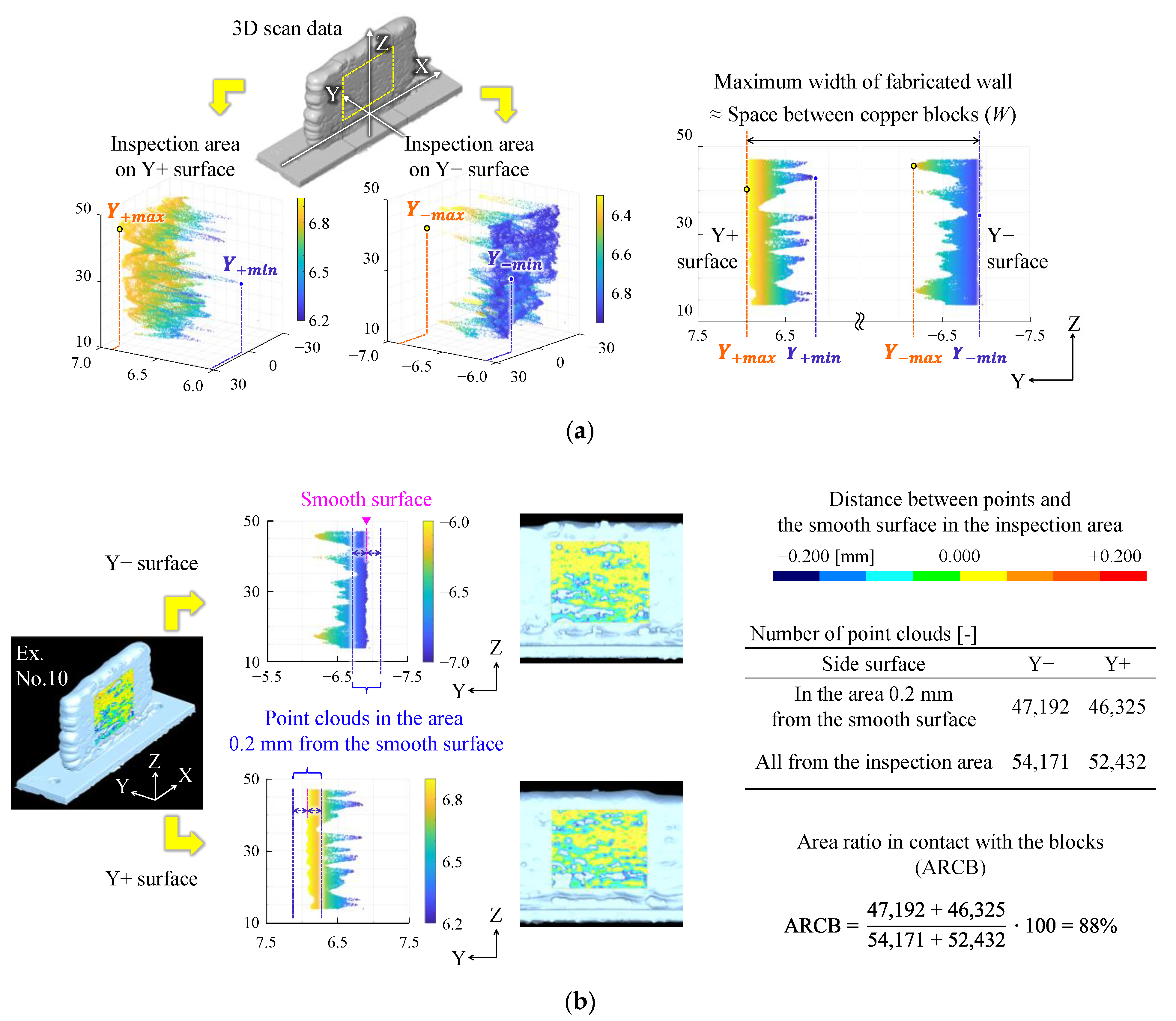
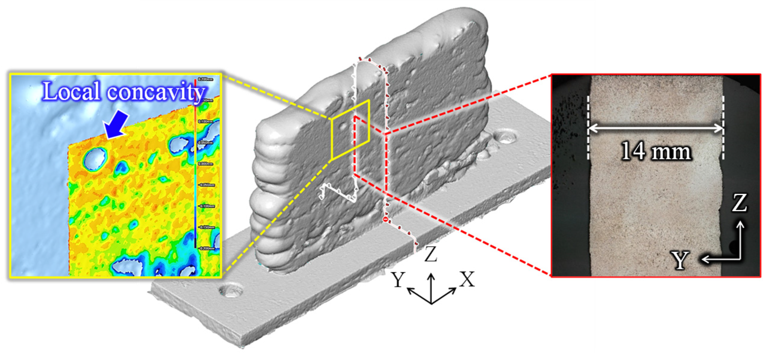
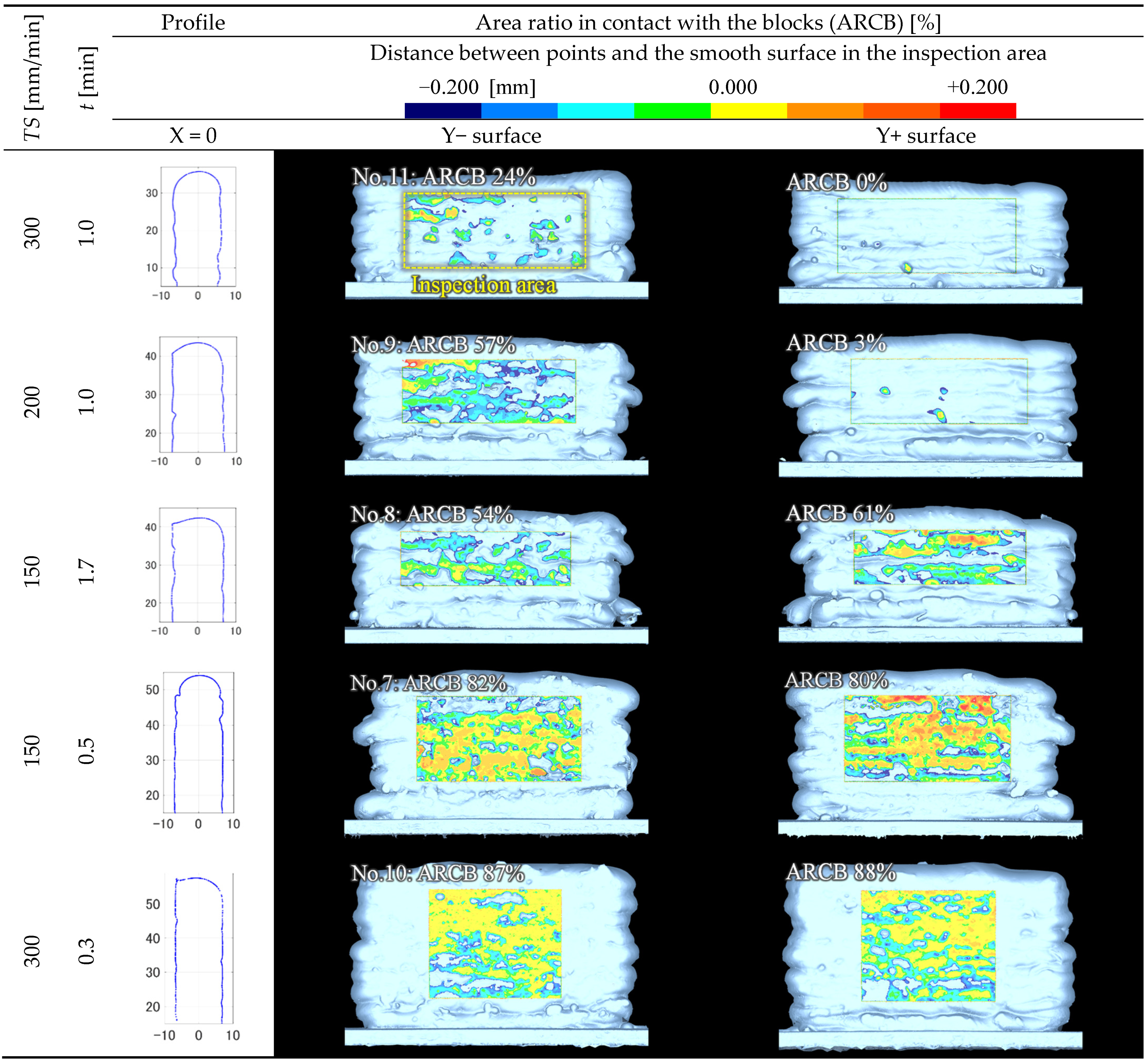
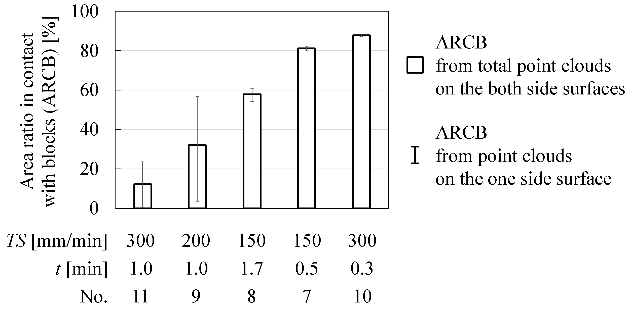
2.6. Measurement and Evaluation of Dimensional Accuracy

The dimensional accuracy for WAAM is generally evaluated on the basis of multiple cross-sectional profiles [35]. In this paper, the dimensions of the entire fabricated objects were measured to evaluate the shape more accurately with a three-dimensional (3D) coordinate measuring machine (VL300, Keyence Corp., Osaka, Japan). In the proposed methods, the width of the fabricated wall equates approximately to W. Therefore, the surface unevenness and the Area Ratio in Contact with the Blocks (ARCB) were evaluated to compare the dimensional accuracy between the fabricated walls of different widths. The calculation of the surface unevenness and ARCB are shown in Figure 8a,b, respectively. The X-, Y-, and Z-axes are along the longitudinal, width, and height directions, respectively. The inspection area represents the −30 ≤ X ≤ 30 [mm] area of the fabricated part comprised of type B or C. The surface unevenness and ARCB were calculated from the point cloud data located on the side surface in the inspection area.
The surface unevenness refers to the average of the maximum difference between the concave and convex portions of the two side surfaces. When the maximum and minimum values of the Y coordinates of the point cloud data located on the Y+ and Y− sides are Y + max , Y + min , Y max , and Y min , respectively, the surface unevenness is calculated from the following equation.
Surface   unevenness = ( Y + m a x Y + m i n ) + | Y m a x Y m i n | 2
ARCB represents the ratio of the total number of point clouds in the area 0.2 mm from the smooth surface uniformed by the copper block to the total number of all point cloud data in the inspection area as shown in Figure 8b.

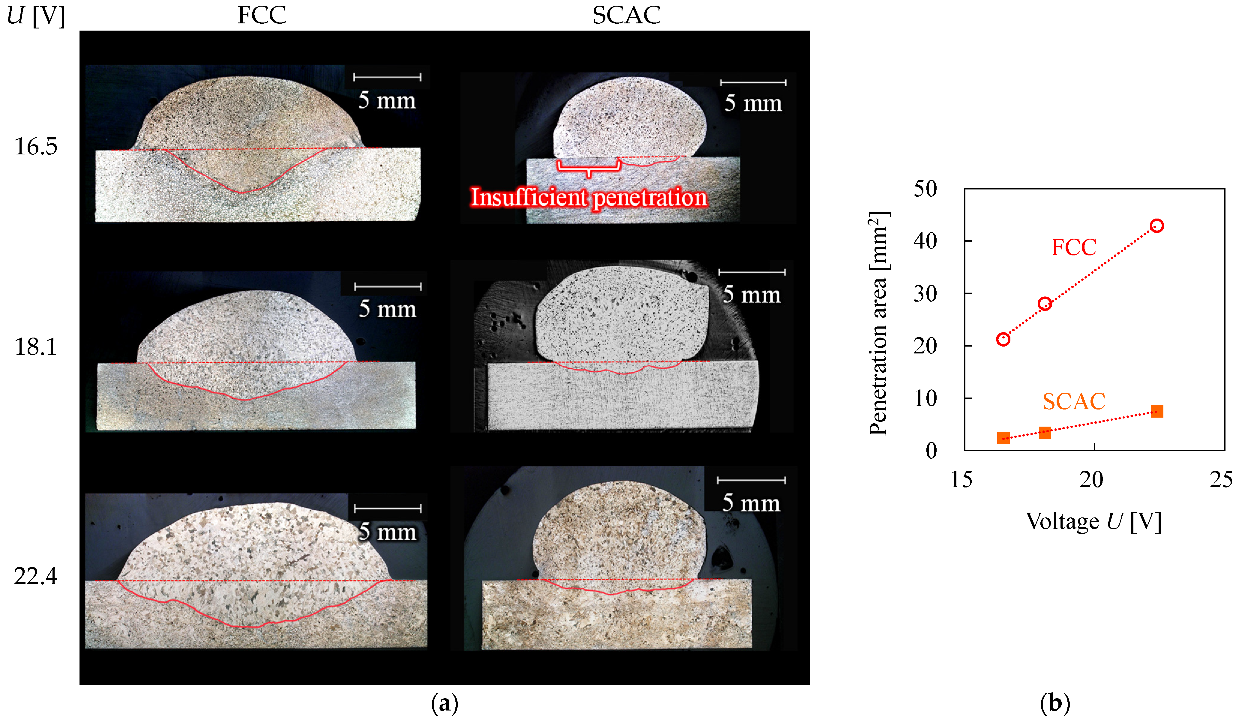
2.7. Measurement of Penetration Area of AZ31 Bead

The cross sections of the resin-filled specimens were polished with SiC papers (1000 and 2000 grit), after cutting an 80 mm length near the center of the bead via electrical discharge machining. Subsequently, the cross section of the specimen was polished again with 6 and 1 µm diamond grains. The polished surfaces of the specimens were macro-etched in a mixture of 5 g picric acid, 5 mL acetic acid, 10 mL diluted water, and 100 mL ethanol at room temperature for about 20 s to clear the penetration boundary. After macro-etching, the penetration area was measured using a digital microscope (VHX-6000, Keyence Corp., Osaka, Japan).

3. Results and Discussion

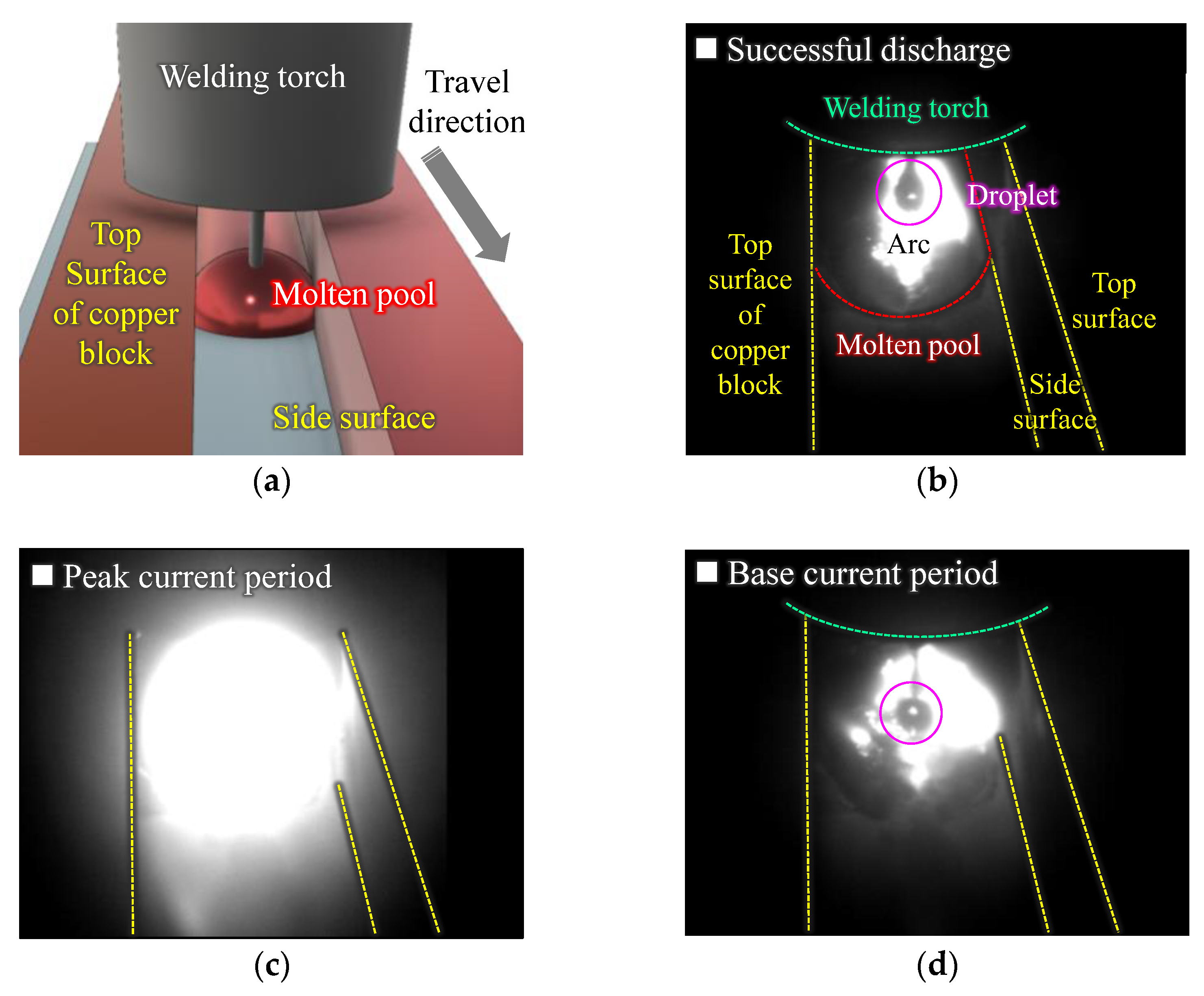
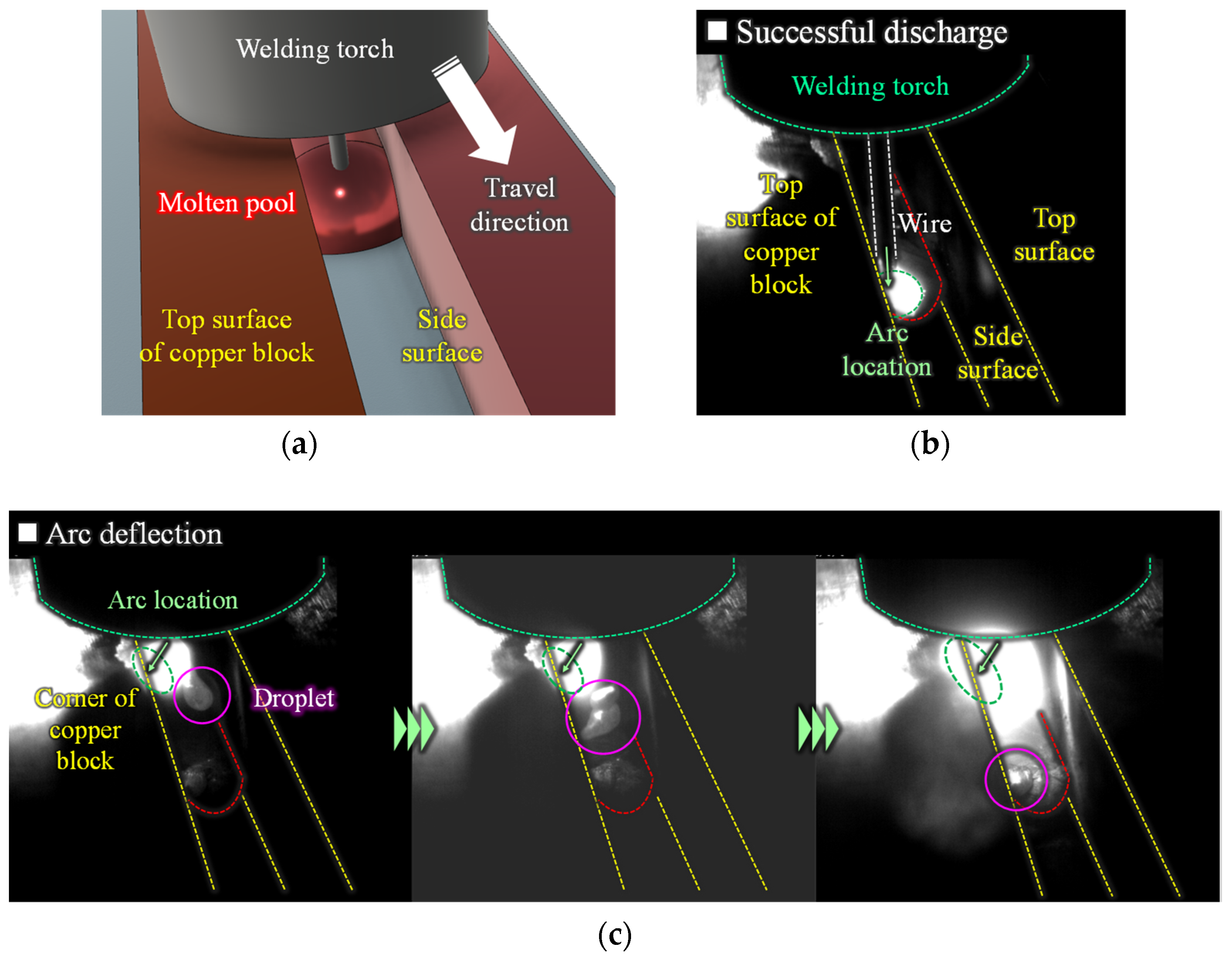
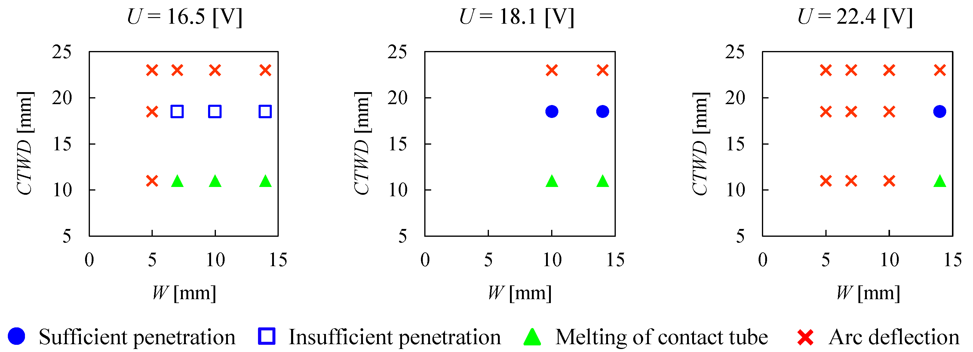
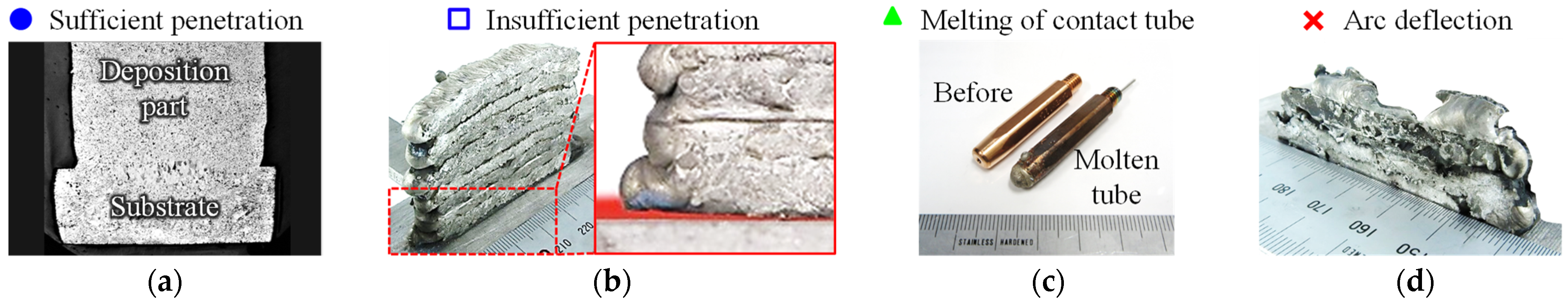
3.1. Effects of the Copper Blocks on Arc Deflection and Bead Formation

First, the effects of W on the arc and the molten pool are described. When W ≥ 10 [mm], the arc generated normally. The observation by high-speed camera (IDP-ExpressR2000, PHOTRON LIMITED., Tokyo, Japan) of droplet transfer during stable discharge is shown in Figure 9. The experimental conditions are W = 14 [mm], CTWD = 18.5 [mm], and U = 22.4 [V]. Figure 9b illustrates that the arc was generated between the wire tip and the substrate and that droplets formed at the wire tip. The droplets grew larger with each pulse period (Figure 9c) and transferred to the molten pool on the substrate (Figure 9d). This droplet transfer is typical of globule migration and is caused by the physical properties of Mg [36]. In general, the thermal pinch effect triggers the droplets formed at the tip of the wire to transfer. However, in the case of Mg alloy with low surface tension, the droplets did not release easily and tended to expand beyond the wire diameter.
On the other hand, when W ≤ 7 [mm], arc deflection toward the copper blocks was frequently observed due to the approach of the wire tip to the copper blocks. Figure 10 shows droplet transfer during a normal arc and an arc deflection under the experimental conditions: W = 7 [mm], CTWD = 18.5 [mm], and U = 22.4 [V]. Figure 10b illustrates a normal arc, and Figure 10c shows the discharged arc at the corner of the copper block. While the arc deflected, the molten pool on the base metal did not grow and the droplets that left the wire tip landed on the substrate, which subsequently solidified and accumulated. Therefore, W ≥ 10 [mm] exhibited the successful fabrication range of W to prevent arc deflection within this experimental environment.
Next, the effects of CTWD on the arc and bead formation are described. Figure 11 and Figure 12 show the effects of W, CTWD, and U on arc deflection, penetration, and bead formation of the Mg alloy using processing condition No. 0. The circle, square, triangle, and cross marks indicate sufficient penetration, insufficient penetration, melting of the contact tube, and arc deflection toward the copper blocks, respectively. In the case of CTWD = 23 [mm], the arc deflected toward the copper blocks due to the large curvature wire. The poor bead appearance is illustrated in Figure 12d. On the other hand, when CTWD = 11 [mm], the arc generated on the substrate successfully, but the feeding wire failed frequently due to melting of the contact tube as shown in Figure 12c. This illustrates that the electrode extension was insufficient for the arc length in CTWD = 11 [mm]. From the information above, CTWD was controlled to approximately 18.5 mm to prevent welding errors in the subsequent experiments.
Finally, the effects of U on arc deflection and bead penetration are described. As shown in Figure 11, an increase of U narrows the successful fabrication range. A higher U increased the arc length and caused arc deflection. Figure 13 shows the relationship between U and the bead penetration area by FCC or SCAC (CTWD = 18.5 [mm] and W = 14 [mm]). The penetration areas in both FCC and SCAC increase with an increase of U and the penetration area in SCAC is significantly smaller than that in FCC. In, SCAC and U = 16.5 [V], the fabricated bead bears the smallest penetration area and fusion failure as shown in Figure 13a. In the multilayer fabrication experiment using the same conditions, the edges of the fabricated walls detached easily from the substrate due to thermal stress as illustrated in Figure 12b.
Three factors may have contributed to the fusion failure. The first is the lowering of the temperature around the molten pool by the copper blocks. The cooling effect of the blocks on the fabricated object is described in Section 3.2. The second factor is that the molten metal flowing forward in the torch travel direction prevented arc discharge between the wire tip and the substrate. Generally, molten metal flows in the opposite direction of the torch travel direction due to Marangoni convection in the welding process [37]. The molten metal also spreads in the width direction as the surface tension of the molten pool decreases with increasing temperature. However, when the copper blocks are located at both ends of the fabrication path, the temperature at the end of the molten pool decreases due to contact with the copper blocks, and the molten metal is expected to solidify more quickly than FCC. In addition, copper blocks restrict the flow direction of the molten metal, especially in the width direction. Therefore, it is expected that the molten metal, which should flow backward, flowed forward in the torch travel direction, thus preventing the arc from discharging on the substrate. The third reason is that large spatters accumulated forward in the torch travel direction. The spatter which normally scatters in all directions was repelled by the copper blocks and accumulated in the gaps between them. In this case, both the accumulated spatter and substrate must be melted to achieve sufficient penetration between the substrate and the fabricated bead; a low voltage such as 16.5 V represents insufficient thermal energy.
Thus, the range of W ≥ 10 [mm], CTWD   18.5 [mm], 18.1 ≤ U ≤ 22.4 [V] describes the successful fabrication range to prevent arc deflection and fusion failure in the experimental environment of this study. In the experimental fabrication of multilayers described in Section 3.2 and Section 3.3, two conditions were adopted: (i) W = 14 [mm], U = 22.4 [V] and (ii) W = 10 [mm], U = 18.1 [V]. To fabricate wall structures with a width of less than 10 mm and without fusion failure, it is important to reduce spatter or wire curvature. For example, it is expected that TIG welding, which generates minimal spatter, can achieve this. Alternatively, establishing a current waveform control suitable for MIG welding using an Mg alloy, which realizes one pulse and one drop, may alleviate the limitations concerning the processing conditions applicable to SCAC.

3.2. Temperature of Fabricated Wall and Copper Block

First, the heat transfer performance of the copper block in SCAC and SCACW is described. Figure 14a shows the temperature history of the fabricated walls and the copper blocks in FCC, SCAC, and SCACW on the next-to-last layer during the interval. The processing conditions are W = 14 [mm], U = 22.4 [V], t     2 [min] (Numbers 4, 12, and 16). Figure 14b illustrates the direction of heat transmission during arc discharge and the dwell period in SCAC and SCACW. The temperatures of the copper block and fabricated walls decrease with time during the dwell period. The temperatures of the fabricated walls in FCC and SCAC at 40 s after the arc stops are 216 °C and 189 °C, respectively, and the temperature of the copper block in SCAC immediately after the arc stops is 235 °C. These results indicate that a portion of the heat energy added to the fabricated wall from the arc is effectively transferred from the fabricated wall to the copper block. However, the temperature decrease rate in SCAC was lower than that in FCC, and the fabricated wall in SCAC just before fabrication of the next layer is hotter than that in FCC. This is due to heat dissipation of the copper block being lower than that of the fabrication wall, and the heat is thus transferred from the hot copper block to the fabrication wall as shown in Figure 14b. It is expected that the direction of heat transfer between the solid copper block and the fabricated wall becomes reversed during arc discharge and within the dwell period. On the other hand, regarding SCACW, the temperature of the copper block immediately after the arc ceased measured 20 °C. The temperature of the fabricated wall 40 s after the arc stopped measured 124 °C. The temperatures of the copper block and the fabricated wall in SCACW were reduced by about 200 °C and 60 °C, respectively, compared to those in SCAC. It was considered that most of the heat energy transferred from the wall to the block subsequently transferred to the cooling water circulating inside the block as shown in Figure 14b. In addition, the block in SCACW was constantly maintained at room temperature regardless of the occurrence of an arc. Therefore, it seems the heat transfer performance of the block in SCACW was not impaired during arc discharge. This trend observed in the heat transfer performance of the copper blocks was confirmed under all processing conditions.
Figure 15 shows the temperature measurement results for each layer of the fabricated wall. The processing conditions in Figure 15a,b were W = 14 [mm], U = 22.4 [V], t     2 [min] (Numbers 4, 12, and 16) and W = 10 [mm], U = 18.1 [V], t     2 [min] (Numbers 2, 6, and 14), respectively. Figure 15c illustrates the average temperature of five layers: the fifth-from-last layer to the last layer. The fabricated wall temperatures are shown from highest to lowest in the order FCC, SCAC, and SCACW regardless of W. The temperature of the fabricated wall increases with the number of layers, but the rate of temperature increase near the last layer is lower than that at the beginning of fabrication. As shown in Figure 15c, the average temperatures of the walls with W = 14 [mm] in FCC, SCAC, and SCACW are 205 °C, 187 °C, and 132 °C, respectively, indicating that the copper blocks improved the heat dissipation of the walls.
Next, the effects of W on the fabrication wall and copper block temperatures are described. Figure 15c shows the average temperatures of the fabricated walls with W = 10 [mm] in FCC, SCAC, and SCACW are 199 °C, 161 °C, and 63 °C, respectively, which are generally lower than those of the walls with W = 14 [mm]. In particular, the average temperature of the wall with W = 10 [mm] in SCACW was about 70 °C lower than that for W = 14 [mm]. Figure 16 illustrates the maximum temperature of the copper block during arc discharge for each layer in SCAC and SCACW. In the case of SCAC with t = 2.0 [min], the maximum temperature of the copper block with W = 10 [mm] is higher than that with W = 14 [mm], as shown in Figure 16a. This is due to an increase in the bead height per layer with a decrease in the width of the fabricated wall, resulting in an increase in the contact area with the copper block. The bead heights per layer with W = 10 [mm] and W = 14 [mm] were 4.2 mm and 3.2 mm, respectively, and the 29% decrease in W resulted in a 24% increase in the bead height per layer. Therefore, increasing the contact area with the block was expected to improve the heat transferred to it.
Finally, the effects of t and TS on the temperature of the block are discussed. Figure 16a,b illustrates the temperature of the block in SCAC increased with a shorter t or lower TS. Notably, the temperature of the copper block was increased to about 600 °C during arc discharge by shortening t. In contrast, the maximum temperatures of the copper block with t = 0.3 [min] and t = 2.1 [min] in SCACW were 48 °C and 26 °C, respectively, with little difference in temperature. In addition, the copper block temperature decreased approximately to water temperature within a few seconds after the arc stopped. Therefore, the shortening of t bears little effect on the copper block temperature in SCACW.

3.3. Effects of Copper Block and Processing Parameters on Dimensional Accuracy

Figure 17 and Figure 18 illustrate the scan data of the walls fabricated by FCC, SCAC, and SCACW, and the measurement results of the surface unevenness of the walls by TS = 300 [mm/min], respectively. In all experiments with SCAC or SCACW, the copper blocks did not melt and were easily detached from the fabricated walls. Any potential metallurgical bond did not form at the interface between the copper block and fabricated walls of the Mg alloy due to the high thermal conductivity of pure copper and wide differences in physical and mechanical properties between Mg and copper [38].
First, a comparison between FCC and SCAC is described. In the case of FCC using a high heat input condition, TS = 150 [mm/min], a multilayer could not be fabricated even with the longest dwell time: t = 4.2 [min] (No. 1). The fabricated wall became extremely hot and the molten metal accumulated as the second layer flowed down to the substrate. When TS = 300 [mm/min], representing half of the input heat used in the previous condition, the multilayer could be fabricated (Numbers 3, 4). However, the surface unevenness increased significantly with shorter t, as shown in Figure 18. Therefore, to improve the dimensional accuracy of the fabricated wall in FCC, it is necessary to extend the dwell time for each layer, thereby enhancing the efficiency of the whole fabrication process. On the other hand, in the case of SCAC with TS = 150 [min] and t = 0.5 [min] (No. 7), 10 layers were successfully fabricated despite the shorter t compared to FCC. The surface unevenness of the fabricated wall by SCAC decreases significantly with decreasing t. In particular, the unevenness of the fabricated wall measured 2.6 mm in FCC with t = 2.5 [min] (No. 4), whereas it measured 0.8 mm in SCAC with t = 0.3 [min] (No. 10), indicating SCAC can achieve both a high efficiency of the whole fabrication process and dimensional accuracy. It is considered that the continuous heat input raised the temperature around the molten pool, resulting in the Mg alloy molten metal with low surface tension spreading over the entire space between the copper blocks.
The scan data and the cross section of the fabricated wall with the smallest surface unevenness in all experimental results are shown in Figure 19 (No. 10, SCAC, t = 0.3 [min], W = 14 [mm]). In the case of SCAC using t ≤ 0.5 [min], the formation of grooves on the boundary of each layer, a common observation in WAAM objects, was noted as barely forming. On the other hand, there were a number of local concavities with depths of about 1 mm. It is considered that the remelting of the large spatter which accumulated between copper blocks caused the formation of the local concavities. The collection of large spatter was remelted by the molten pool and the arc approaching from behind, but some spatter weakly melded with the fabricated wall was easily detached. Therefore, to improve the dimensional accuracy obtained by this method, it remains necessary to establish spatterless welding conditions or welding principles for Mg alloy.
Next, the effects of TS and t on the ARCB are discussed. The ARCB and scanning data of fabricated walls using the conditions SCAC and TS = 150, 200, and 300 [mm/min] are shown in Figure 20. Figure 21 illustrates that ARCB increases, and the uniformity of ARCB on both sides improves, with decreasing TS when t ≥ 1.0 [min] (Numbers 8, 9, and 11). These results are attributed to the increase in deposition rate and heat input per unit bead length by decreasing TS, which allows the expanded molten metal to contact the copper block uniformly. The near 0% ARCB on the Y+ side using the conditions TS = 200, 300 [mm/min] and t ≥ 1.0 [min] is attributed to a deviation in the position of droplet transfer due to the curvature of the wire tip. On the other hand, in the case of t ≤ 0.5 [min], ARCB exhibited great improvement compared to t ≥ 1.0 [min]. In particular, when TS = 300 [mm/min] (Numbers 10, 11), ARCB increased from 23% to 88% by shortening t from 1.0 min to 0.3 min, which is equivalent to the ARCB of a fabricated wall using the conditions TS = 150 [mm/min] and t = 0.5 [min] (No. 7). This suggests that continuous discharge promotes higher temperature in the fabricated wall more than an increase in heat input. From the above, it was identified that both sides of the wall can be smoothened by increasing the heat input or shortening t in SCAC.
Finally, the effects of W and the cooling water circulating inside the copper block on the dimensional accuracy of the fabricated wall are discussed. In the cases of SCAC and SCACW, the dimensional accuracy improves with a shortening of t, as shown in Figure 18. On the other hand, the surface unevenness of the fabricated wall becomes larger by SCACW than by SCAC; in addition, exhibiting a tendency to increase as W decreases. When focusing on t ≤ 0.5 [min] as illustrated in Figure 18, the levels of surface unevenness by SCACW with W = 14 [mm] and 10 [mm] are 0.3 mm and 0.7 mm greater than those of SCAC, respectively. The decrease in dimensional accuracy is attributed to the improved cooling performance of the copper block via internal water cooling. Figure 22 shows the scan data and cross section of the fabricated wall with the largest surface unevenness in SCACW (No. 14, SCACW, t = 2.1 [min], W = 10 [mm]). In the conditions using t ≥ 1 [min] or SCACW, grooves formed on the boundary of each layer. This is because the contact angle of the molten metal during solidification increases due to decreases in the temperature of the fabricated wall.
From these results, it was discovered the dimensional accuracy of the walls decreased as the cooling performance of the block improved. However, SCACW bears the potential to overcome issues in SCAC and to further improve both the dimensional accuracy and efficiency of the whole fabrication process of WAAM. Since the copper block in SCAC becomes hotter due to the shortening of t and an increase in the number of layers as shown in Figure 16a, the cooling performance may decrease significantly depending on the volume of the block. In contrast, the block in SCACW remained constantly below 50 °C so that the cooling performance in SCACW could be maintained even with more than 20 layers. This suggests that the grooves displayed in Figure 22 can be improved by further shortening t.
In future studies, multilayer experiments with t < 0.2 [min] in SCACW will be conducted. Regarding these experiments, in addition to dimensional accuracy, the grain size and mechanical properties of the fabrication walls will also be observed to assess the effectiveness of SCACW. In addition, a cold roller comprised of copper in place of a copper block, will be adapted as a heat transportation structure to increase the degrees of geometrical freedom of fabricated objects. The rolling process-assisted WAAM can achieve the fabrication of a large-scale component bearing a complicated curved surface [39]. Moreover, the high rolling load is effective for controlling residual stresses and distortion, and increasing the hardness of WAAM parts [40]. Eventually, SCACW will be implemented into the WAAM method using an Mg alloy to fabricate large-scale components such as a wing rib with a high deposition rate and dimensional accuracy.

4. Conclusions

In this study, a solid contact-based active cooling system using copper blocks (SCAC), and SCAC with an internal water circulation (SCACW), were proposed as new WAAM cooling methods for Mg alloys, in order to improve the dimensional accuracy and cooling efficiency. The following results were obtained.
(1)
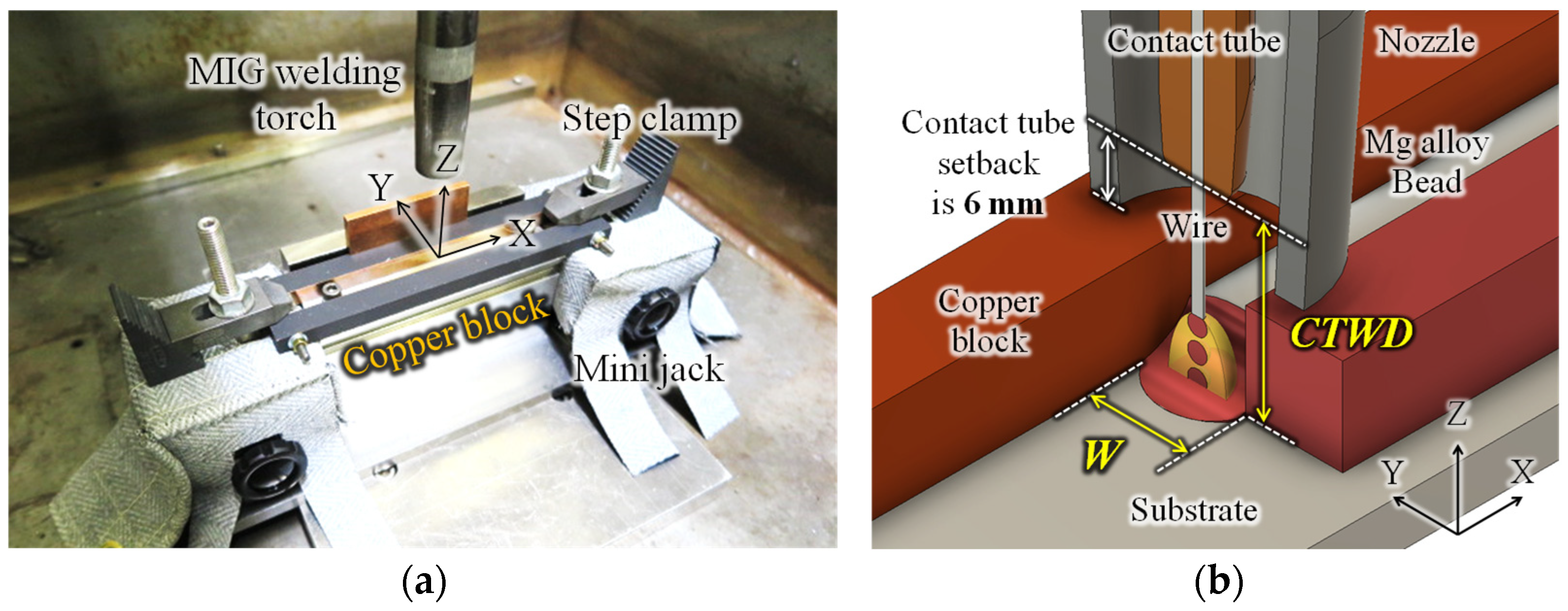
When the tip of the wire approached the copper blocks, an arc deflected toward the blocks and not onto the substrate or the previous layer, thus forming a bead with a poor appearance. Therefore, fabrication of a suitable bead remains important to control the contact tube to work distance and the width of the space between the blocks.
(2)
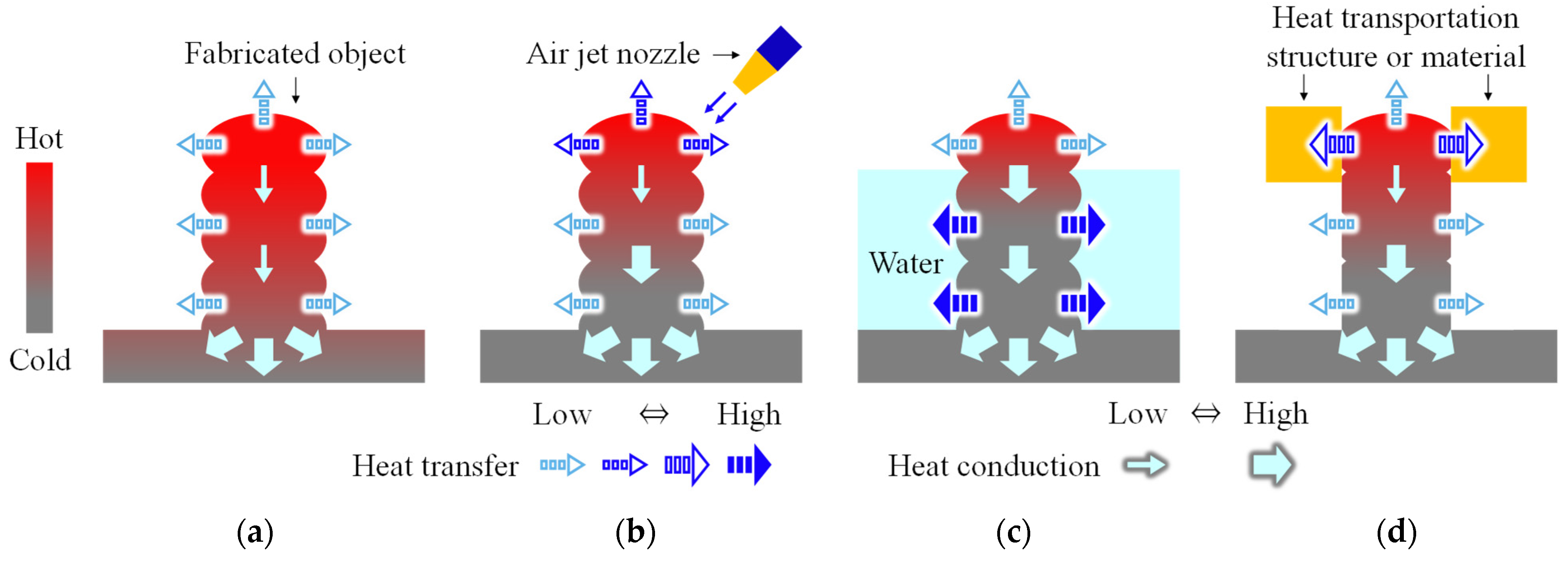
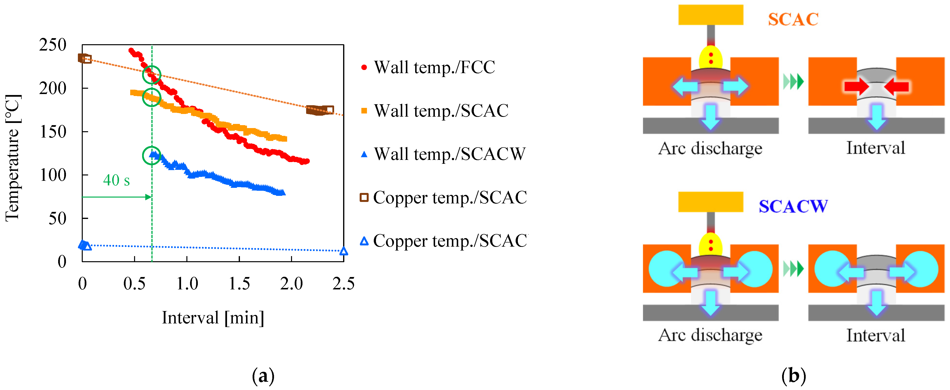
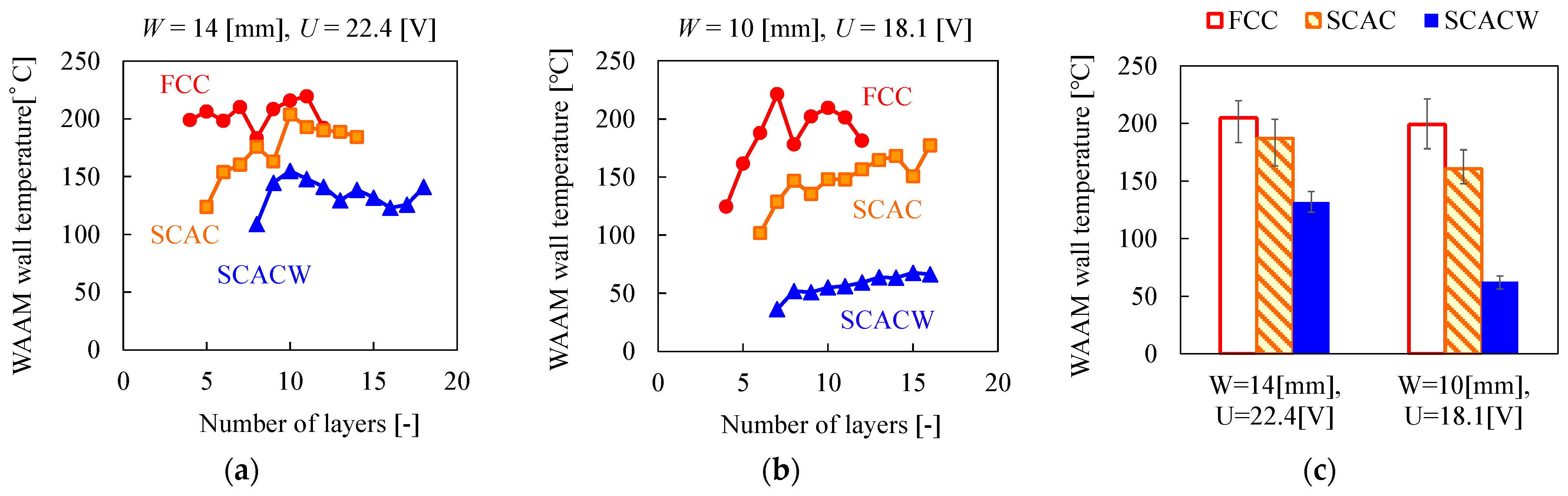
The interpass temperature decreased in the order of free convection cooling (FCC), SCAC, and SCACW, indicating that the fabrication wall cooled upon contact with the copper block.
(3)
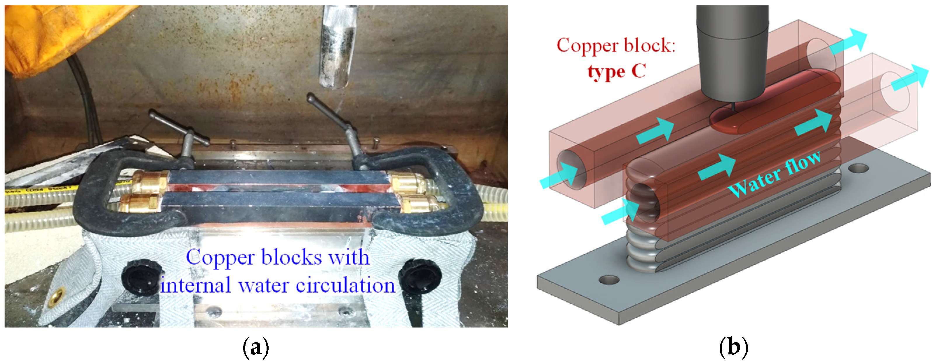
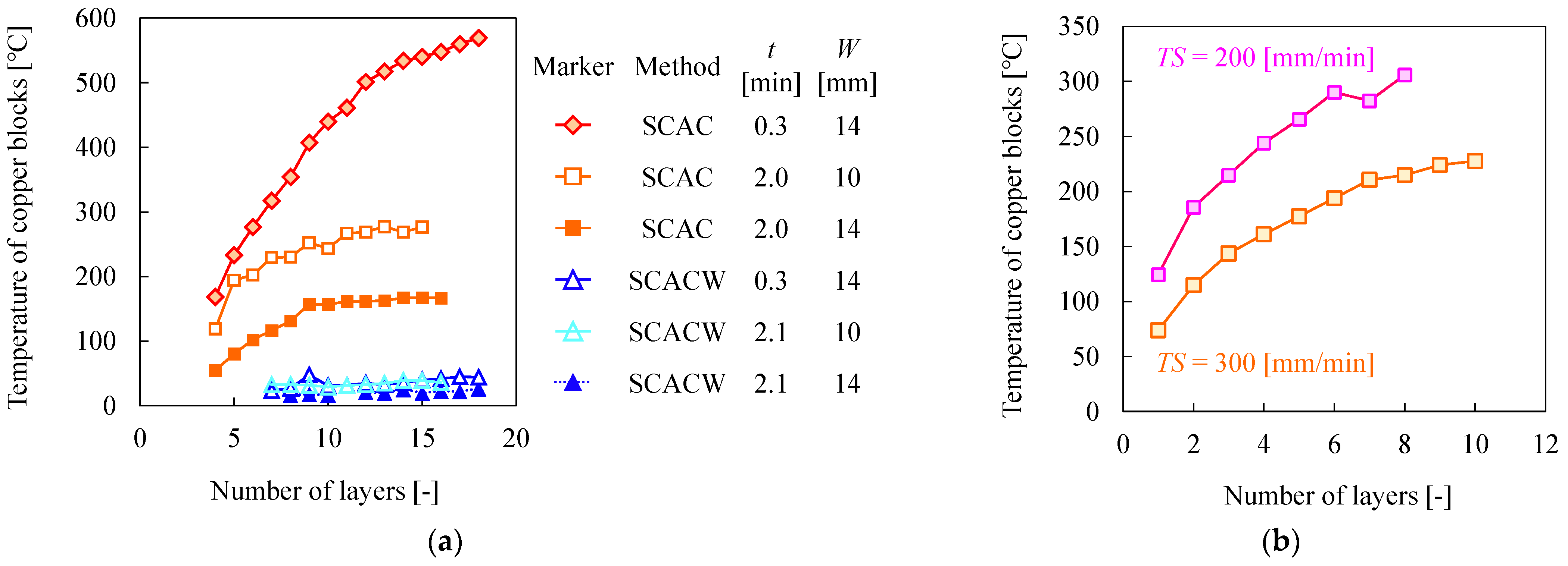
In the case of SCAC, the temperature of the copper block at the time of arc discharge increased to approximately 600 °C by shortening the dwell time. In contrast, the block temperature remained constantly below 50 °C in the case of SCACW. This indicates that the block’s cooling performance can be maintained via cold water circulating inside the block.
(4)
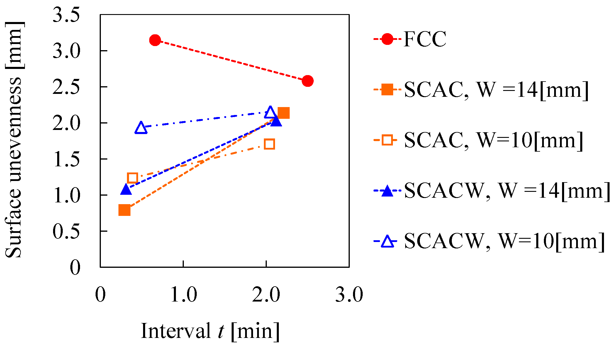
In the case of FCC, dwell time extension is required for stable fabrication. In contrast, regarding SCAC and SCACW, the dimensional accuracy of the walls improved as dwell time shortened.
(5)
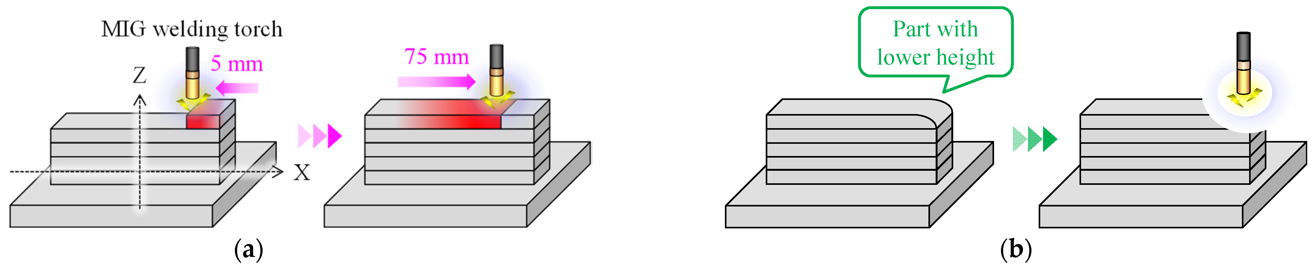
The bottom neck of the dimensional accuracy of the walls in SCAC results from the remelting of a collection of large spatter generated during arc discharge. Meanwhile, in SCACW, the grooves between the layers formed due to the copper block’s excessively higher cooling performance compared to the temperature of the WAAM object. Therefore, to further improve dimensional accuracy, it remains necessary to prevent spatter and to deposit Mg alloy continuously.

Author Contributions

Conceptualization, H.N. and H.S.; Data curation, H.N.; Funding acquisition, H.N. and H.S.; Investigation, H.N.; Methodology, H.N.; Project administration, H.N. and H.S.; Resources, H.S.; Supervision, H.S.; Visualization, H.N.; Writing—original draft, H.N.; Writing—review & editing, H.N. and H.S. All authors have read and agreed to the published version of the manuscript.

Funding

This work was supported by KAKENHI (19H02038) and Grant-in-Aid for JSPS Fellows (20J11467).

Acknowledgments

We acknowledge Japan Fine Steel Co., Ltd. for supplying the Mg alloy wire.

Conflicts of Interest

The authors declare no conflict of interest.

Glossary

AMAdditive Manufacturing
WAAMWire and Arc Additive Manufacturing
PBFPowder Bed Fusion
DEDDirected Energy Deposition
MIGMetal Inert Gas
TIGTungsten Inert Gas
CNCComputer Numerical Control
3DThree dimensional
FCCFree Convection Cooling
SCACSolid Contact-based Active Cooling using copper blocks
SCACWSolid Contact-based Active Cooling using copper blocks with an internal Water circulation
ARCBArea Ratio in Contact with Blocks
TSTravel Speed
CTWDContact Tube to Work Distance
WWidth of space between copper blocks
UAverage output voltage
tDwelling time per layer

References

  1. Mordike, B.L.; Ebert, T. Magnesium Properties-Applications-Potential. Mater. Sci. Eng. A 2001, 302, 37–45. [Google Scholar] [CrossRef]
  2. Kumar, D.; Phanden, R.K.; Thakur, L. A Review on Environment Friendly and Lightweight Magnesium-Based Metal Matrix Composites and Alloys. Mater. Today Proc. 2021, 38, 359–364. [Google Scholar] [CrossRef]
  3. Yang, Y.; Xiong, X.; Chen, J.; Peng, X.; Chen, D.; Pan, F. Research Advances in Magnesium and Magnesium Alloys Worldwide in 2020. J. Magnes. Alloys 2021, 9, 705–747. [Google Scholar] [CrossRef]
  4. Wei, K.; Gao, M.; Wang, Z.; Zeng, X. Effect of Energy Input on Formability, Microstructure and Mechanical Properties of Selective Laser Melted AZ91D Magnesium Alloy. Mater. Sci. Eng. A 2014, 611, 212–222. [Google Scholar] [CrossRef]
  5. Liu, C.; Zhang, M.; Chen, C. Effect of Laser Processing Parameters on Porosity, Microstructure and Mechanical Properties of Porous Mg-Ca Alloys Produced by Laser Additive Manufacturing. Mater. Sci. Eng. A 2017, 703, 359–371. [Google Scholar] [CrossRef]
  6. Salehi, M.; Seet, H.L.; Gupta, M.; Farnoush, H.; Maleksaeedi, S.; Ling, M.; Nai, S. Rapid Densification of Additive Manufactured Magnesium Alloys via Microwave Sintering. Addit. Manuf. 2020, 37, 101655. [Google Scholar] [CrossRef]
  7. Nakama, D.; Katoh, K.; Tokisue, H. Some Characteristics of AZ31/AZ91 Dissimilar Magnesium Alloy Deposit by Friction Surfacing. Mater. Trans. 2008, 49, 1137–1141. [Google Scholar] [CrossRef] [Green Version]
  8. Al-Kazzaz, H.; Medraj, M.; Cao, X.; Jahazi, M. Nd:YAG Laser Welding of Aerospace Grade ZE41A Magnesium Alloy: Modeling and Experimental Investigations. Mater. Chem. Phys. 2008, 109, 61–76. [Google Scholar] [CrossRef]
  9. Guo, Y.; Quan, G.; Jiang, Y.; Ren, L.; Fan, L.; Pan, H. Formability, Microstructure Evolution and Mechanical Properties of Wire Arc Additively Manufactured AZ80M Magnesium Alloy Using Gas Tungsten Arc Welding. J. Magnes. Alloys 2021, 9, 192–201. [Google Scholar] [CrossRef]
  10. Wang, P.; Zhang, H.; Zhu, H.; Li, Q.; Feng, M. Wire-Arc Additive Manufacturing of AZ31 Magnesium Alloy Fabricated by Cold Metal Transfer Heat Source: Processing, Microstructure, and Mechanical Behavior. J. Mater. Process. Technol. 2021, 288, 116895. [Google Scholar] [CrossRef]
  11. Yang, X.; Liu, J.; Wang, Z.; Lin, X.; Liu, F.; Huang, W.; Liang, E. Microstructure and Mechanical Properties of Wire and Arc Additive Manufactured AZ31 Magnesium Alloy Using Cold Metal Transfer Process. Mater. Sci. Eng. A 2020, 774, 138942. [Google Scholar] [CrossRef]
  12. Bi, J.; Shen, J.; Hu, S.; Zhen, Y.; Yin, F.; Bu, X. Microstructure and Mechanical Properties of AZ91 Mg Alloy Fabricated by Cold Metal Transfer Additive Manufacturing. Mater. Lett. 2020, 276, 128185. [Google Scholar] [CrossRef]
  13. Takagi, H.; Sasahara, H.; Abe, T.; Sannomiya, H.; Nishiyama, S.; Ohta, S.; Nakamura, K. Material-Property Evaluation of Magnesium Alloys Fabricated Using Wire-and-Arc-Based Additive Manufacturing. Addit. Manuf. 2018, 24, 498–507. [Google Scholar] [CrossRef]
  14. Shen, X.; Ma, G.; Chen, P. Effect of Welding Process Parameters on Hybrid GMAW-GTAW Welding Process of AZ31B Magnesium Alloy. Int. J. Adv. Manuf. Technol. 2018, 94, 2811–2819. [Google Scholar] [CrossRef]
  15. Guo, J.; Zhou, Y.; Liu, C.; Wu, Q.; Chen, X.; Lu, J. Wire Arc Additive Manufacturing of AZ31 Magnesium Alloy: Grain Refinement by Adjusting Pulse Frequency. Materials 2016, 9, 823. [Google Scholar] [CrossRef] [PubMed] [Green Version]
  16. Zhang, H.; Hu, S.; Wang, Z.; Liang, Y. The Effect of Welding Speed on Microstructures of Cold Metal Transfer Deposited AZ31 Magnesium Alloy Clad. Mater. Des. 2015, 86, 894–901. [Google Scholar] [CrossRef]
  17. Gale, W.F.; Totemeier, T.C. Smithells Metals Reference Book, 8th ed.; Butterworth-Heinemann: Oxford, UK, 2004. [Google Scholar]
  18. Zhao, H.; Zhang, G.; Yin, Z.; Wu, L. A 3D Dynamic Analysis of Thermal Behavior during Single-Pass Multi-Layer Weld-Based Rapid Prototyping. J. Mater. Process. Technol. 2011, 211, 488–495. [Google Scholar] [CrossRef]
  19. Montevecchi, F.; Venturini, G.; Grossi, N.; Scippa, A.; Campatelli, G. Idle Time Selection for Wire-Arc Additive Manufacturing: A Finite Element-Based Technique. Addit. Manuf. 2018, 21, 479–486. [Google Scholar] [CrossRef]
  20. Hackenhaar, W.; Mazzaferro, J.A.E.; Montevecchi, F.; Campatelli, G. An Experimental-Numerical Study of Active Cooling in Wire Arc Additive Manufacturing. J. Manuf. Process. 2020, 52, 58–65. [Google Scholar] [CrossRef]
  21. Le, V.T.; Mai, D.S.; Paris, H. Influences of the Compressed Dry Air-Based Active Cooling on External and Internal Qualities of Wire-Arc Additive Manufactured Thin-Walled SS308L Components. J. Manuf. Process. 2021, 62, 18–27. [Google Scholar] [CrossRef]
  22. Kozamernik, N.; Bračun, D.; Klobčar, D. WAAM System with Interpass Temperature Control and Forced Cooling for Near-Net-Shape Printing of Small Metal Components. Int. J. Adv. Manuf. Technol. 2020, 110, 1955–1968. [Google Scholar] [CrossRef]
  23. Kamioka, T.; Abe, T.; Ishikawa, S.; Sasahara, H. Influence of the Cooling Method of the Molten Pool on the Laminating Characteristics in Direct Metal Lamination by Using Arc Discharge. Trans. Jpn. Soc. Mech. Eng. Part C 2012, 78, 282–291. [Google Scholar] [CrossRef] [Green Version]
  24. Reisgen, U.; Sharma, R.; Mann, S.; Oster, L. Increasing the Manufacturing Efficiency of WAAM by Advanced Cooling Strategies. Weld. World 2020, 64, 1409–1416. [Google Scholar] [CrossRef]
  25. Da Silva, L.J.; Teixeira, F.R.; Araújo, D.B.; Reis, R.P.; Scotti, A. Work Envelope Expansion and Parametric Optimization in Waam with Relative Density and Surface Aspect as Quality Constraints: The Case of Al5mg Thin Walls with Active Cooling. J. Manuf. Mater. Process.g 2021, 5, 40. [Google Scholar] [CrossRef]
  26. Da Silva, L.J.; Souza, D.M.; de Araújo, D.B.; Reis, R.P.; Scotti, A. Concept and Validation of an Active Cooling Technique to Mitigate Heat Accumulation in WAAM. Int. J. Adv. Manuf. Technol. 2020, 107, 2513–2523. [Google Scholar] [CrossRef]
  27. Li, F.; Chen, S.; Shi, J.; Zhao, Y.; Tian, H. Thermoelectric Cooling-Aided Bead Geometry Regulation in Wire and Arc-Based Additive Manufacturing of Thin-Walled Structures. Appl. Sci. 2018, 8, 207. [Google Scholar] [CrossRef] [Green Version]
  28. Zhang, A.; Xing, Y.; Yang, F.; Zhang, X.; Wang, H.; Yu, T. Development of a New Cold Metal Transfer Arc Additive Die Manufacturing Process. Adv. Mater. Sci. Eng. 2021, 2021, 9353820. [Google Scholar] [CrossRef]
  29. Patel, V.; Li, W.; Liu, X.; Wen, Q.; Su, Y.; Shen, J.; Fu, B. Tailoring Grain Refinement through Thickness in Magnesium Alloy via Stationary Shoulder Friction Stir Processing and Copper Backing Plate. Mater. Sci. Eng. A 2020, 784, 139322. [Google Scholar] [CrossRef]
  30. Del Valle, J.A.; Rey, P.; Gesto, D.; Verdera, D.; Jiménez, J.A.; Ruano, O.A. Mechanical Properties of Ultra-Fine Grained AZ91 Magnesium Alloy Processed by Friction Stir Processing. Mater. Sci. Eng. A 2015, 628, 198–206. [Google Scholar] [CrossRef] [Green Version]
  31. Chen, Y.; Fang, C.; Yang, Z.; Wang, J.; Wu, M.; Chen, S. A Study on Sidewall Penetration of Cable-Type Welding Wire Electrogas Welding. Weld World 2017, 61, 979–986. [Google Scholar] [CrossRef]
  32. Henckell, P.; Gierth, M.; Ali, Y.; Reimann, J.; Bergmann, J.P. Reduction of Energy Input in Wire Arc Additive Manufacturing (WAAM) with Gas Metal Arc Welding (GMAW). Materials 2020, 13, 2491. [Google Scholar] [CrossRef] [PubMed]
  33. Venturini, G.; Montevecchi, F.; Bandini, F.; Scippa, A.; Campatelli, G. Feature Based Three Axes Computer Aided Manufacturing Software for Wire Arc Additive Manufacturing Dedicated to Thin Walled Components. Addit. Manuf. 2018, 22, 643–657. [Google Scholar] [CrossRef]
  34. Sanders, P.G.; Keske, J.S.; Leong, K.H.; Kornecki, G. High Power Nd:YAG and CO2 Laser Welding of Magnesium. J. Laser Appl. 1999, 11, 96–103. [Google Scholar] [CrossRef]
  35. Kazanas, P.; Deherkar, P.; Almeida, P.; Lockett, H.; Williams, S. Fabrication of Geometrical Features Using Wire and Arc Additive Manufacture. J. Eng. Manuf. 2012, 226, 1042–1051. [Google Scholar] [CrossRef]
  36. Zhang, Z.D.; Liu, L.M.; Song, G. Welding Characteristics of AZ31B Magnesium Alloy Using DC-PMIG Welding. Trans. Nonferrous Met. Soc. China 2013, 23, 315–322. [Google Scholar] [CrossRef]
  37. Gu, Y.; Hua, X.; Ye, D.; Li, F.; Ma, X.; Xu, C. Numerical Simulation of Hump Suppression in High-Speed Triple-Wire GMAW. Int. J. Adv. Manuf. Technol. 2016, 89, 727–734. [Google Scholar] [CrossRef]
  38. Liming, L.; Shengxi, W.; Limin, Z. Study on the Dissimilar Magnesium Alloy and Copper Lap Joint by TIG Welding. Mater. Sci. Eng. A 2008, 476, 206–209. [Google Scholar] [CrossRef]
  39. Xie, Y.; Zhang, H.; Zhou, F. Improvement in Geometrical Accuracy and Mechanical Property for Arc-Based Additive Manufacturing Using Metamorphic Rolling Mechanism. J. Manuf. Sci. Eng. 2016, 138, 111002. [Google Scholar] [CrossRef]
  40. Hönnige, J.R.; Colegrove, P.A.; Ganguly, S.; Eimer, E.; Kabra, S.; Williams, S. Control of Residual Stress and Distortion in Aluminium Wire + Arc Additive Manufacture with Rolling. Addit. Manuf. 2018, 22, 775–783. [Google Scholar] [CrossRef] [Green Version]
Figure 1. General kinds of cooling strategies and heat dissipation during wire and arc additive manufacturing (WAAM). (a) Free convection cooling (FCC). (b) Air jet active cooling. (c) Water-based active cooling. (d) Solid contact-based active cooling.
Jmmp 06 00027 g001
Figure 2. Three types of copper blocks; Type A: 200 mm × 15 mm × 10 mm, Type B for SCAC: 200 mm × 15 mm × 15 mm, Type C for SCACW: 200 mm × 22 mm × 22 mm with a long hole of Φ 14.5 mm.
Jmmp 06 00027 g002
Figure 3. Solid contact-based active cooling using copper blocks (SCAC). (a) Experimental setup. (b) Schematic setup.
Jmmp 06 00027 g003
Figure 4. SCAC with an internal water circulation (SCACW). (a) Experimental setup. (b) Schematic setup.
Jmmp 06 00027 g004
Figure 5. Deposition strategy for wall structure of Mg alloy. (a) Travel direction for odd layers. (b) Additional deposition on the lower edge point.
Jmmp 06 00027 g005
Figure 6. Application and timing of the replacement of the copper blocks. (a) Fabrication process from first layer to several layers using type A copper. (b) Free convection cooling. (c) Fabrication process using type B or C.
Jmmp 06 00027 g006
Figure 7. Schematic diagram of the measurement setup for the current waveforms and temperatures of the fabricated object and the copper block. (a) Temperature measurement of a copper block during arc discharge. (b) Interpass temperature measurement of top layer during the dwell period. (c) Example of the measurement history of the arc current and temperatures of the copper block and the fabricated wall.
Jmmp 06 00027 g007
Figure 8. Measurement and evaluation of dimensional accuracy of the fabricated wall by a 3D scanner. (a) Graphical explanation of the calculation of surface unevenness. (b) Graphical explanation of the calculation of the area ratio in contact with the blocks (ARCB).
Jmmp 06 00027 g008
Figure 9. High-speed images of arc generation and droplet transfer using the conditions needed for sufficient penetration (space between copper blocks (W) = 14 [mm], average output voltage (U) = 22.4 [V], metal inert gas (MIG) welding contact tube to work distance (CTWD) = 18.5 [mm]). (a) Angle of view. (b) Growing droplet at the wire tip during base current period. (c) Peak current period. (d) A large droplet transferred to the molten pool.
Jmmp 06 00027 g009
Figure 10. High-speed images of arc generation and droplet transfer using inadequate conditions with arc deflection (W = 7 [mm], U = 22.4 [V], CTWD = 18.5 [mm]). (a) Angle of view. (b) Successful arc generation on the substrate. (c) Arc discharged at the corner of the copper block.
Jmmp 06 00027 g010
Figure 11. Effects of W, CTWD, and U on welding penetration and arc deflection by SCAC.
Jmmp 06 00027 g011
Figure 12. (a) Cross-section of the multilayer wall showing sufficient penetration. (b) Incomplete fusion between the substrate and the fabricated wall. (c) Melting of the contact tube by arc heat. (d) Poor appearance resulting from arc deflection.
Jmmp 06 00027 g012
Figure 13. Relationship between voltage and penetration area in FCC or SCAC (W = 14 [mm], CTWD = 18.5 [mm]). (a) Cross sections of the fabricated single bead. (b) Measurement results of the penetration area.
Jmmp 06 00027 g013
Figure 14. Heat transfer performance of the copper block in SCAC and SCACW. (a) Interpass temperature history of WAAM walls and copper blocks on the next-to-last layer during the interval (W = 14 [mm], U = 22.4 [V], dwell time ( t )     2 [min]). (b) Direction of heat transmission during arc discharge and interval in SCAC and SCACW.
Jmmp 06 00027 g014
Figure 15. Interpass temperatures of fabricated walls 40 s after stopping the arc. (a) W = 14 [mm], U = 22.4 [V], t     2 [min]. (b) W = 10 [mm], U = 18.1 [V], t     2 [min]. (c) Average temperature of five layers: the fifth-from-last layer to the last layer.
Jmmp 06 00027 g015
Figure 16. Maximum temperature of coppers blocks during arc discharge. (a) Effect of the copper block, W, and t (TS = 300 [mm/min]). (b) Effect of torch feed speed (TS) (SCAC, W = 14 [mm], U = 22.4 [V], t     1 [min]).
Jmmp 06 00027 g016
Figure 17. Appearance and scan data of all fabricated walls.
Jmmp 06 00027 g017
Figure 18. Influences of interval time t and SCAC on surface unevenness (U = 22.4 [V], TS = 300 [mm/min]).
Jmmp 06 00027 g018
Figure 19. Fabricated wall with the smallest surface unevenness in all experiments (No. 10, SCAC, t = 0.3 [min], W = 14 [mm], U = 22.4 [V], TS = 300 [mm/min]).
Jmmp 06 00027 g019
Figure 20. Appearance of fabricated walls with color distribution to show ARCB (SCAC, W = 14 [mm], U = 22.4 [V]).
Jmmp 06 00027 g020
Figure 21. Influences of TS and t on ARCB (SCAC, W = 14 [mm], U = 22.4 [V]).
Jmmp 06 00027 g021
Figure 22. Fabricated wall with the largest surface unevenness and grooves formed on the boundary of each layer in SCACW (No. 14, SCACW, t = 2.1 [min], W = 10 [mm], U = 18.1 [V], TS = 300 [mm/min]).
Jmmp 06 00027 g022
Table 1. Chemical composition of the AZ31 magnesium (Mg) alloy wire (mass%).
MaterialAlZnMnSiFeCuNiMg
AZ312.50.70.20.300.0050.050.005Bal.
Table 2. Physical properties of the copper blocks used equivalent to JIS standard C1100P.
PropertiesUnitValue
Specific heat-385
Coefficient of expansion10−6·K17.7
Thermal conductivityW/(m·K)391
Electroconductivity%IACS≥97
Liquidus temperature°C1083
Solidus temperature°C1065
Table 3. Common processing parameters.
ParametersUnitName or Value
Welding machine-DAIHEN P500L
Welding mode-DC pulse
Average output currentA106
Deposition ratecm3/h774
AZ31 wireFeed speedm/min11.4
Diametermm1.2
Shielding gasAr%99.99
Flow rateL/min25
Table 4. Individual processing parameters.
Active Cooling
Method
Test
No.
Width of Space between
Copper Blocks
Contact Tube to Work
Distance
Average
Output
Voltage
Travel
Speed
Dwelling Time
Per Layer
Number
of Layers
WCTWDUTSt
- mmmmVmm/minmin-
Solid contact-based active cooling using copper blocks (SCAC)05,
7,
10,
14
11.0,
18.5,
23.0
16.5,
18.1,
22.4
150-1 to 10
Free convection cooling (FCC)1-18.522.41504.22
2-18.518.13002.112
3-18.522.43000.712
4-18.522.43002.512
SCAC51018.518.13000.414
61018.518.13002.016
71418.522.41500.510
81418.522.41501.710
91418.522.42001.010
101418.522.43000.318
111418.522.43001.012
121418.522.43002.214
SCAC with an internal water circulation (SCACW)131018.518.13000.516
141018.518.13002.116
151418.522.43000.322
161418.522.43002.119
Publisher’s Note: MDPI stays neutral with regard to jurisdictional claims in published maps and institutional affiliations.

