Article

A Comparative Study on Fatigue Response of Aluminum Alloy Friction Stir Welded Joints at Various Post-Processing and Treatments

by
Soran Hassanifard
and
Ahmad Varvani-Farahani
*
Department of Mechanical and Industrial Engineering, Ryerson University, 350 Victoria Street, Toronto, ON M5B 2K3, Canada
*
Author to whom correspondence should be addressed.
J. Manuf. Mater. Process. 2021, 5(3), 93; https://doi.org/10.3390/jmmp5030093
Submission received: 24 July 2021 / Revised: 11 August 2021 / Accepted: 18 August 2021 / Published: 20 August 2021
(This article belongs to the Special Issue Frontiers in Friction Stir Welding and Processing)

Abstract

:
The present study examines the fatigue of friction stir welded (FSW) aluminum 6061, 7075, 1060 joints followed by (i) in situ and sequential rolling (SR) processes, (ii) plastic burnishing (iii) solution-treatment artificial aging (STA), (iv) local alloying through depositing thin copper foils, and (v) inserting alumina powder in the weld nugget zone (NZ). The microstructural features and fatigue life of post-processed joints were compared with those of as-welded joints. The in situ rolling technique offered simultaneous rolling and welding operations of aluminum joints, while through the sequential rolling process, the top surface of FSW joints was rolled after the welding process. The fatigue life of in situ rolled samples was increased as the ball diameter of welding tool increased. The fatigue life of friction stir welded joints after a low-plasticity burnishing process was noticeably promoted. The addition of 1 wt.% alumina in the NZ of joints resulted in a significant elevation on fatigue life of friction stir spot welded joints, while an increase in alumina powder to 2.5 wt.% adversely affected fatigue strength. Weld NZ was alloyed through the insertion of copper foils between the faying surfaces of joints. This localized alloy slightly improved the fatigue life of joints; however, its effects on fatigue life were not as influential as STA heat-treated or in situ rolled joints. The microstructure of weld joints was highly affected through post-processing and treatments, resulting in a substantial influence on the fatigue response of FSW aluminum joints.

1. Introduction

Friction stir welding (FSW), which is a prevalent permanent method of joining thin metal sheets, is widely used in different industrial sectors, such as automotive, aerospace, and marine. In the FSW technique, (i) a non-consumable rotating tool with interfacing surfaces is used to generate adequate frictional heat required to join metal sheets, and (ii) the stirring process by means of pin tool plays a crucial role in generating a plastically deformed zone around the pin. This technique is employed to fabricate spot welds on overlapped metal sheets and is referred as friction stir spot welding (FSSW). Excellent mechanical properties, lower possibility of distortion, less hot cracking, low residual stresses, and short welding time have classified FSW as an unprecedented technique over other traditional welding methods [1]. The most important advantage of this class is to join dissimilar materials while preserving excellent mechanical properties [2,3]. FSW structures are often subjected to severe repetitive loadings in service, causing abrupt failure due to the fatigue phenomenon. In an attempt to improve the fatigue resistance of friction stir welded joints, researchers have proposed several techniques including adding nano/micro particles to the weld nugget to create a local metal matrix composites (MMCs) [4,5,6,7], optimizing welding process parameters [8,9,10,11,12] through tool shape and operation rate, introducing novel welding tools with different geometrical features [13,14,15,16,17], inducing compressive residual stresses by means of different methods of cold working [18,19,20,21,22,23], and weld joint post-heat treatment [24,25,26].
Further techniques [4,5,6,7] improved the mechanical properties of the joints through the addition of sufficient amounts of powders/particles into the stirred zone (SZ) of FSW/FSSW joints. Enami et al. [4] added alumina particles to the nugget zone of FSSW aluminum 2024-T3 joints. They reported that adding alumina powder could increase the ultimate tensile strength of the joints up to 23%. Hong et al. [5] reinforced the FSSW joints of dissimilar aluminum alloy samples by adding graphite particles into the nugget zone of the joints. They showed that adding a sufficient amount of graphite particles into the SZ of joints enhanced the tensile strength and toughness values of joints significantly. Bahrami et al. [6] reinforced Al 7075 FSW joints by adding SiC powder in the SZ of weld joints. They showed that addition of well-dispersed SiC powder in the SZ of the weld region could improve tensile strength and fatigue life of joints significantly. Through inserting thin metallic foils between the faying surfaces of Al 7020 weld segments, as shown by Lenin et al. [7], particles of the foil material were dispersed in the SZ followed during the FSW operation, leading to an improvement in mechanical properties of joints. They showed that the alloying process through dispersing a 10 μm zinc foil in the weld region of Al 7020 FSW joints could enhance the tensile strength and impact energy of test specimens.
To optimize the FSW process parameters and further improve mechanical properties, Ren et al. [8] studied FSW joints of Al–Mg–Si alloy plates at different tool transverse speeds. They reported higher tensile strength at a tool traverse speed of 400 mm/min as compared with that at 100 mm/min. Premkumar et al. [9] and Babu et al. [10] tested several FSW joints to propose an optimized set of welding process parameters to achieve better mechanical properties. Lombard et al. [11] optimized FSW process parameters in order to achieve defect-free FSW joints of Al 5083-H321 alloy with highest tensile and fatigue strengths. They found that tool rotational speed was the key factor controlling static and fatigue resistances of joints. Palanivel et al. [12] studied the influence of tool rotational speed and pin geometry on microstructural features and tensile properties of dissimilar FSW joints of Al 5083-H111 and Al 6351-T6 alloys. They found that both parameters played key roles governing the microstructures and tensile strength of joints. FSW samples fabricated by the tool with rotational speed of 950 rpm and square pin profile possessed the highest tensile strength.
The impact of tool geometry/shape on mechanical properties of FSW joints was studied by Ugender et al. [13]. They compared conic-shaped pin tool with simple cylindrical pin tool and concluded that joints fabricated using conic-shaped pin possessed greater ultimate tensile strength values than those fabricated by simple cylindrical pin tool. Su and Wu [14] examined the impact of tool geometry on the plastic flow of Al 2024-T4 FSW joints. In their work, three series of tools with rectangular, triangular, and circular pin shapes were examined. They suggested that due to a refinement in microstructure within the SZ, the largest plastic flow in weld segments was achieved by triangular-shaped pin. The effects of tool geometrical parameters on mechanical properties of FSW joints of Al 6061-T6 joints and dissimilar FSW joints of Al 2024 and Al 7075 were further discussed in Refs. [15,16,17].
Cold working and low-plasticity burnishing (LPB) techniques are effective ways to induce compressive residual stresses in weld regions to improve fatigue strength of FSW/FSSW joints. Hassanifard et al. [18] introduced a novel technique to enhance the fatigue life of aluminum 7075-T6 FSSW joints. They inserted a pin with a relatively larger diameter of the FSSW keyhole in order to induce compressive residual stresses around the hole where the most susceptible point for fatigue cracking existed. This led to an improvement in fatigue life. Through the LPB technique, compressive residual stresses were induced on the top surface of weld segments, resulting in an increase in both static and fatigue strengths of joint specimens [19]. This improvement in mechanical properties of burnished samples of FSW joints has been also verified by Jayaraman et al. [20] and Huang et al. [21]. Prevey et al. [22] studied the effects of LPB process and the residual stress distributions developed by LPB operation in titanium alloy samples. They suggested that the LPB process resulted in better corrosion and fatigue resistance. A recent study [23] verified that the burnishing process on Al 2050 FSW joints decreased the average surface roughness value noticeably, resulting in an improvement in the hardness and fatigue strength of joints.
As an alternative way to reduce undesired tensile residual stresses in weldments, various post-weld heat treatments (PWHT) have been adapted by researchers. Ravi et al. [24] proved that PWHT enhanced fatigue strength of steel welded joints significantly. Edwards and Ramulu [25] suggested that PWHT resulted in an improvement in both ductility and fatigue strength of FSW joints of Ti-6Al-4V. Hassanifard et al. [26] simulated the residual stress distribution in FSW samples of Al 6061-T6 joints after the STA heat treatment processing. They showed that the STA heat treatment reduced the tensile residual stresses induced due to the FSW operation significantly, improving the fatigue strength of joints.
Despite the extensive amount of research in the literature dealing with overall mechanical characteristics of FSW/FSSW joints, the lack of information regarding fatigue response of joints subjected to certain post manufacturing processes is evident. This study intends to address different aspects of the post-processing parameters on fatigue performance and microstructural features of FSW aluminum joints. The influence of cold working processes, heat treatment, and alloying in FSW samples with copper foils, as well as adding alumina powder in the nugget regions of FSSW joints, on the fatigue life and microstructures of aluminum joint samples was studied. The present study further discusses post-processing techniques and their influential parameters adopted by engineers in practice to achieve greater resistance of FSW/FSSW joints undergoing severe cyclic loads.

2. Materials and Methods

Among the potential metallic materials to undergo FSW joining operation, aluminum 1060, 6061 and 7075 alloys have received widespread attention in the automotive and aerospace industries due to their excellent mechanical properties. In this study, the influence of various types of post-processing and treatments on the fatigue performance of friction welded aluminum joints were independently examined: (i) the influence of cold working including in situ/sequential rolling (SR) techniques and the LPB process on the fatigue performance of joint samples was examined, (ii) the microstructural features and fatigue life of joint samples after solution-treatment artificial aging were scrutinized, and (iii) the impact of insertion of copper foils between the faying surfaces and depositing Al2O3 powder to form local MMCs is tested to, respectively, evaluate the fatigue life of FSW and FSSW joints. Joint samples were fatigue tested to the failure stage and fracture surfaces of aluminum joints were investigated through scanning electron microscopy (SEM). Tensile and fatigue tests were conducted using respectively a 25 kN SANTAM STM tensile test machine manufactured in Iran, and a 250 kN Zwick/Roell servo-hydraulic fatigue test machine manufactured in Germany.

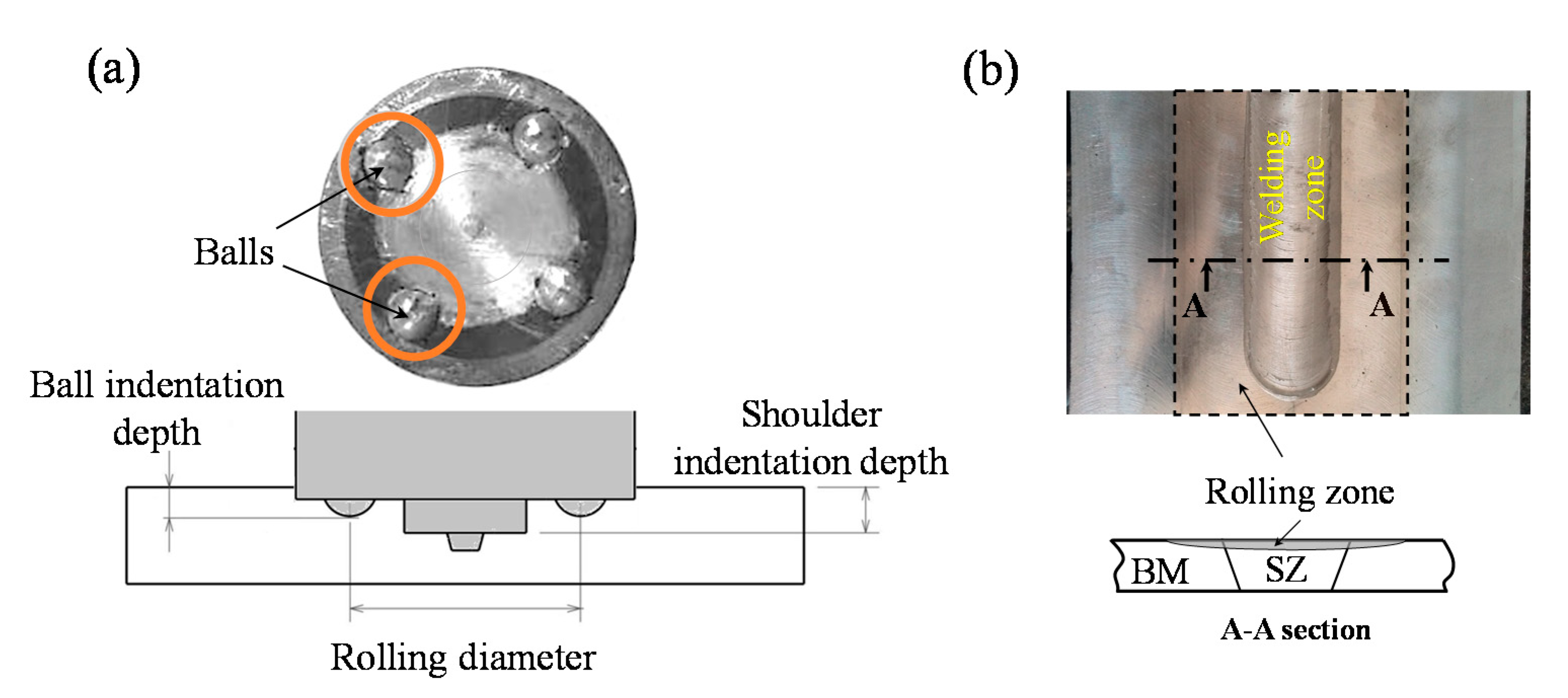
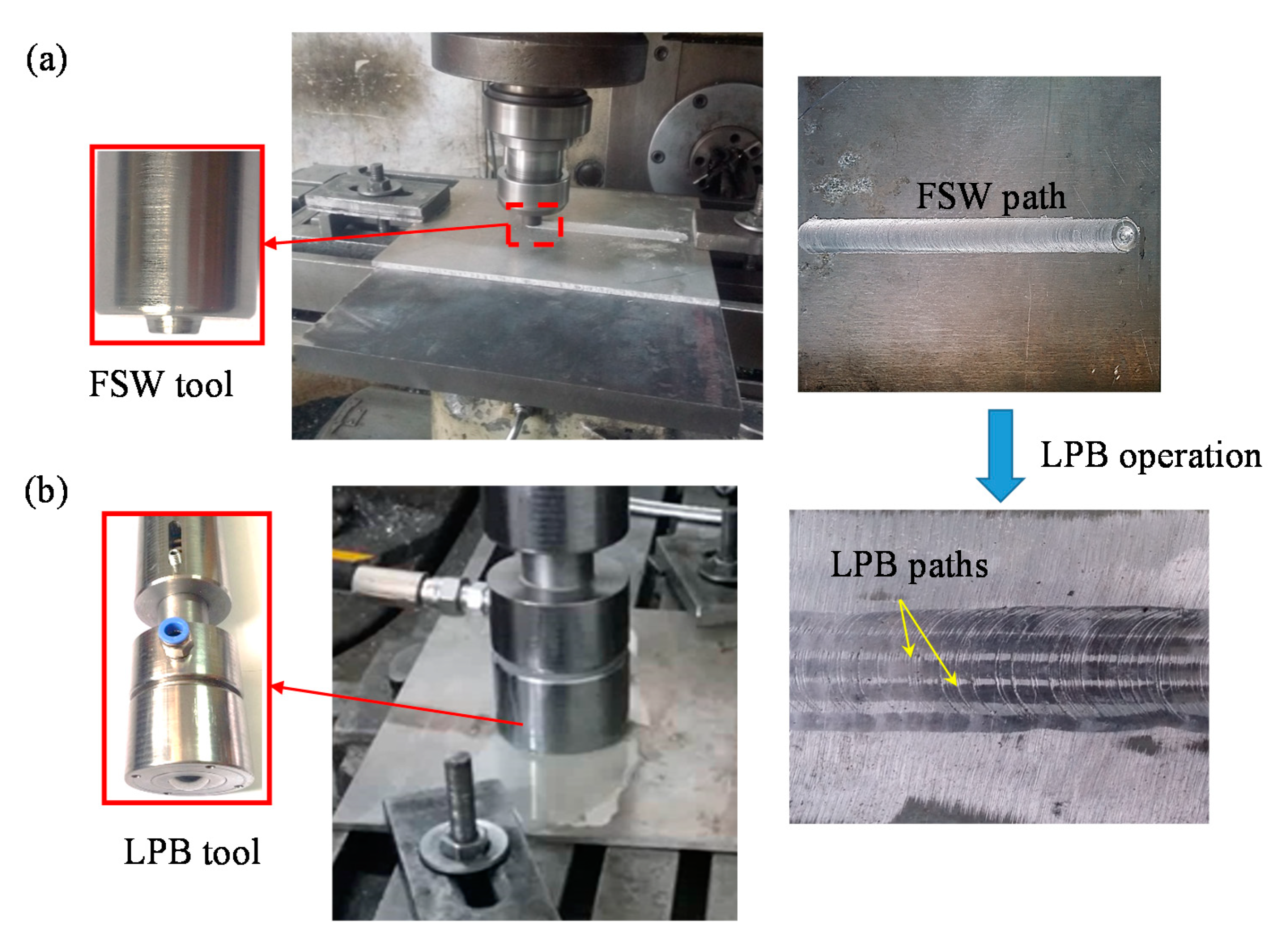
2.1. Cold Working Processes

In order to induce compressive residual stresses and improve fatigue life of joints, two different cold working processes of the in situ/sequential rolling process as well as the LBP technique were carried out on the friction stir welded samples. The in situ/sequential technique was performed on joint samples by means of a custom-made tool with four balls. Two sets of balls with diameters of 6 and 8 mm were taken to further study the effects of ball diameter on fatigue performance. The ball indentation value was selected in such a way that the shoulder penetration maintained its constant depth of 1 mm during the operation through changing gaskets from 0.05 to 0.7 mm. An optimum value for the rolling diameter was found to be equal to 34 mm. While the sequential technique rolled the top surface of friction stir welded joints after the completion of welding process, the in situ rolling process was carried out simultaneously with the FSW operation. The in situ/sequential rolling operation on FSW joints was discussed in detail in Ref. [27]. The rolling tool shape and geometry as well as the rolled joint are presented in Figure 1.
The LPB cold working technique was post-processed on paths of Al 7075-T6 FSW samples to study the effect of induced residual stress on fatigue of burnished joints. To this end, a cylindrical LPB tool was designed and utilized to apply two constant-load magnitudes of 3 and 4 kN on the top surface of joint samples by means of a mechanism of a spring and controlling oil pressure in the back of the tool ball. The diameter of the ball was taken as 30 mm to burnish the entire SZ and HAZ [19]. The LPB process was implemented on five paths reciprocally. Figure 2 presents the LPB tool and the burnished area of the welded joint.

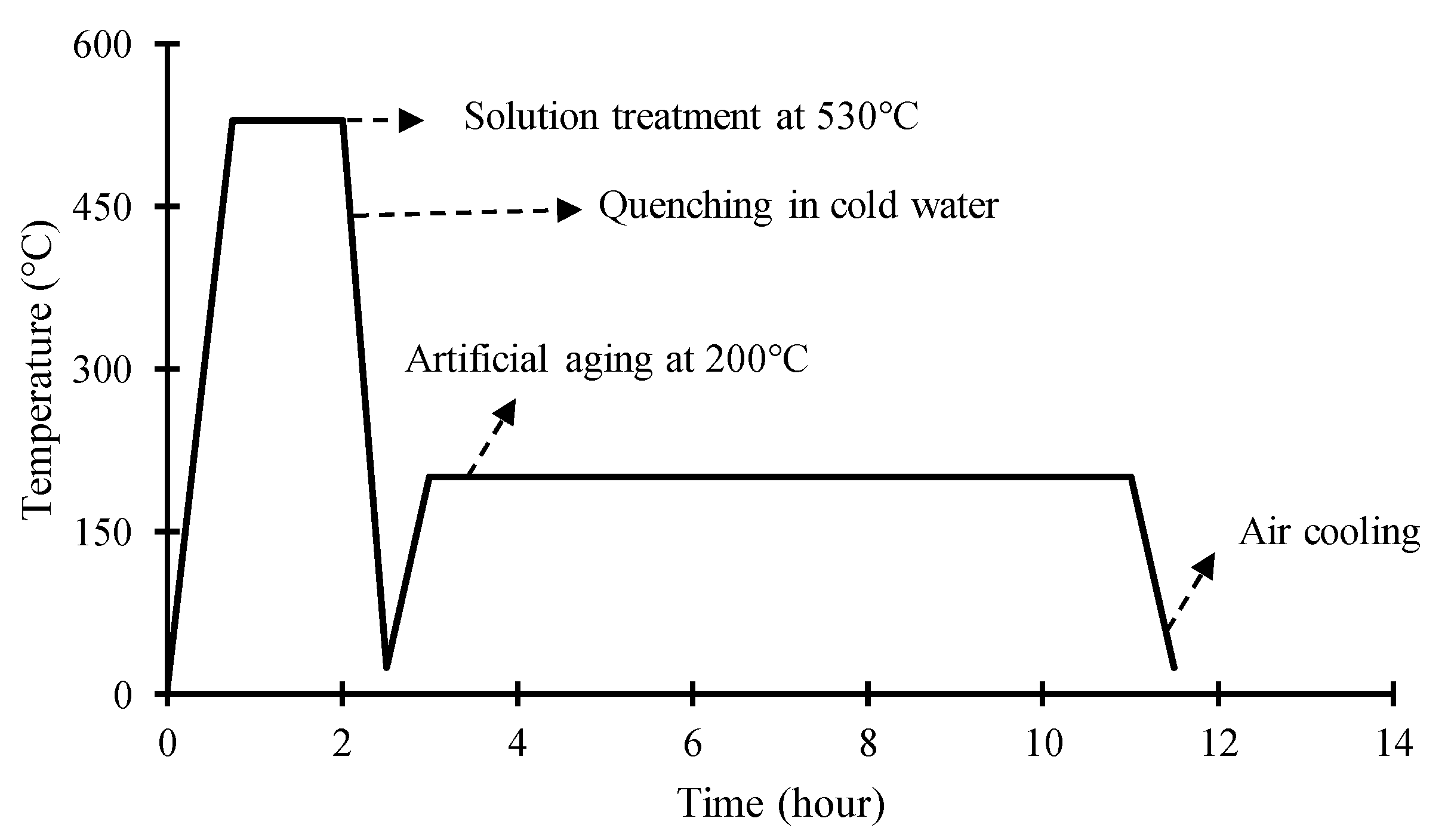
2.2. Post-Weld Heat Treatment

Al 6001-T6 FSW joints were solution heat-treated to examine the fatigue response of joints before and after STA post-processing. The solution heat-treating stage was followed by artificial aging. Figure 3 schematically presents the sequence of the heat-treatment of aluminum joints over the length of the aging time.
The length of aging time over the second step of heat-treatment was controlled to enlarge grain size and disperse second phase precipitates uniformly within main matrix. The quenching of joint samples from 530 °C over the first stage of heat treatment followed by a rapid quenching resulted in a supersaturated solid phase at room temperature. The aging stage was conducted in an intermediate temperature of 200 °C, enabling grains to grow and precipitates to disperse uniformly over a given length of time.

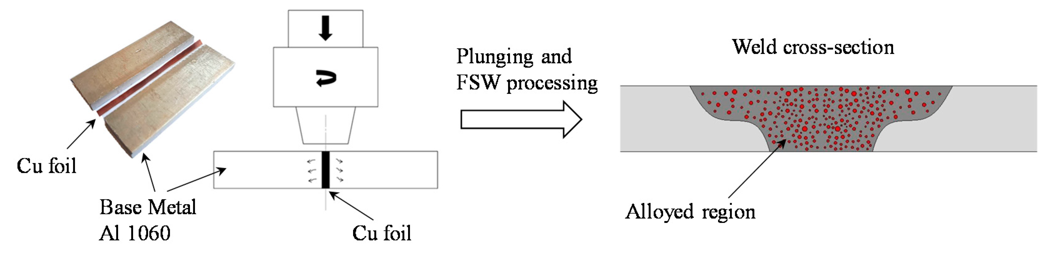
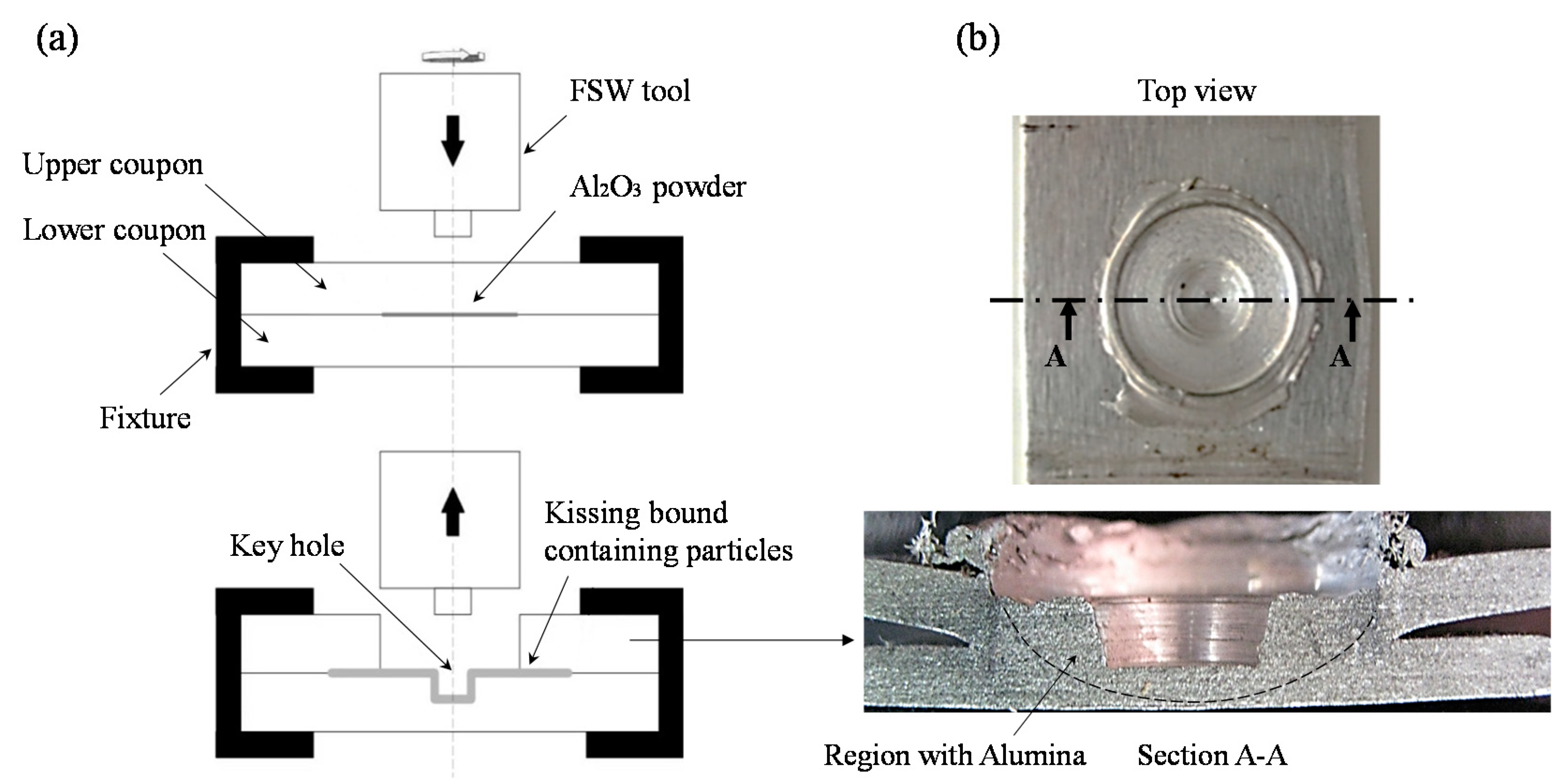
2.3. Alloying and Creating Local MMCs

The effects of inserted thin copper foils with thicknesses of 100 and 200 μm between the faying surfaces of joint sheets were studied to assess fatigue response of Al 1060-H16 FSW joints. The operation of the FSW process in the presence of a thin copper foil between the faying surfaces of sheet joints constructed a localized alloy in the weld central region, affecting the static and fatigue strengths of aluminum joints. Schematic views of the alloying process as well as the joint samples are shown in Figure 4.
Depositing Al2O3 powder into the weld nugget of Al 7075-T6 joints fabricated a local metal matrix composite in the weld region. Alumina particles with sizes ranging between 10 and 20 nm were deposited in the weld region. Joint samples were reinforced with 1 and 2.5 wt.% alumina powder to examine the influence of alumina on the fatigue lives of joint samples. The process of creating MMC through the addition of alumina powder in the weld nugget is schematically shown in Figure 5. Figure 5a presents the process of the insertion of alumina powder between aluminum sheets followed by the FSSW operation. The joint sample in Figure 5b was then prepared to perform the fatigue test under uniaxial loading cycles.
The details on the process parameters and friction welding operations, including the rotational speed (RS), linear transverse speed (LTS), tool tilt angle, pin and shoulder diameters/lengths for conducted tests on aluminum joints, are tabulated in Table 1.

3. Results and Discussion

3.1. Tensile Test Results

To study the influence of post-processing techniques on the mechanical properties of FSW/FSSW joins, quasi-static tensile tests were conducted on joint samples. Figure 6 presents the static stress–strain curves for base-metal as well as post-processed aluminum joint samples.
While the in situ rolling technique and the STA heat treatment noticeably enhanced the ultimate tensile strength of post-processed FSW samples, the sequential rolling technique and the LPB operation showed no major impact on the tensile strength of joints (See Figure 6b). This is attributed to the fact that plastic deformation after FSW operation is not as influential as in situ process in grain refinements.
The impact of inserting 100 μm-thick copper foil between the faying surfaces of the FSW joints on tensile strength was greater than that of 200 μm-thick copper foil. Due to the solubility limit of copper in the aluminum matrix, the brittle intermetallic compound was generated in the SZ, resulting in a slight decrease in the tensile strength of joints with the 200 μm-thick Cu foil as compared to those with the 100 μm-thick Cu foil.
Depositing 1 wt.% alumina particles in the NZ of FSSW joints improved both the tensile strength and ductility as compared to those of as-welded samples. Addition of 2.5 wt.% alumina particles, however, resulted in a slight reduction in the tensile strength and also adversely affected the ductility. Adding large amounts of particles in the NZ of FSSW joints not only caused the agglomeration of particles in the stirred zone, but also reduced the joint area, resulting in a reduction in strength and ductility.
The tensile test results of aluminum joint samples including ultimate tensile strength and elongation examined in this study are listed in Table 2. The details of the testing conditions are found in Refs. [19,26,27,28].

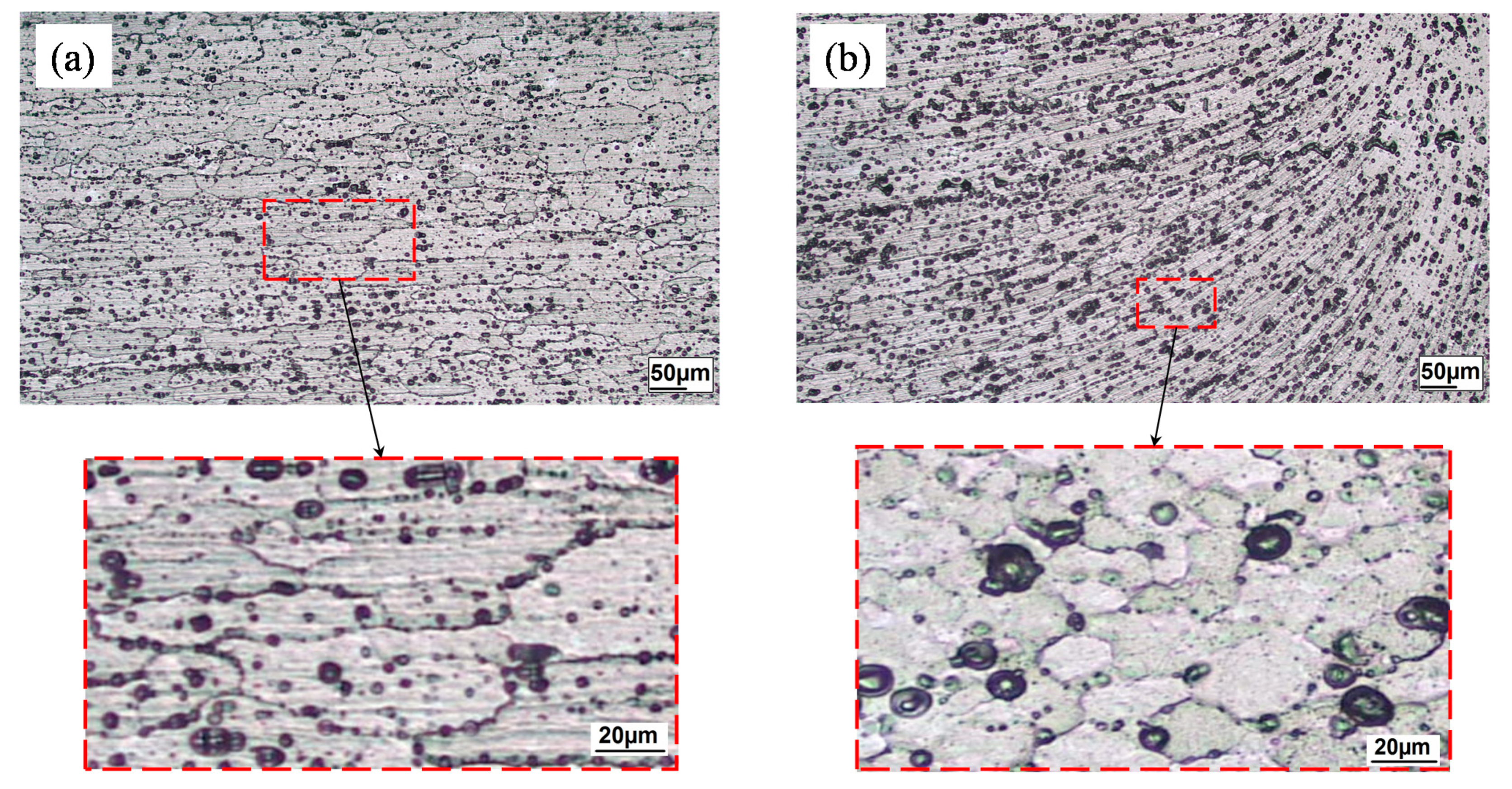
3.2. Microstructural Features of Joint Samples

Post-processing and heat treatment of aluminum FSW/FSSW joints have noticeably influenced microstructural features within weld regions, affecting the fatigue strength and fracture surface of tested joints. Grains and grain boundaries within the weld regions of FSW/FSSW joints were examined through the use of optical microscopy with a magnification of 1000×. Figure 7 presents microstructures within HAZ of the advancing side of the joints that underwent in situ rolling and that of as-welded joints. This figure shows that in situ rolled joints not only possessed more uniformly dispersed second phase particles in the rolled regions, but also formed more refined grains within the HAZ. Aluminum joints post-processed through LPB operation and sequential rolling techniques resulted in no significant grain refinement, while joints undergoing the in situ rolling technique demonstrated substantial evidence of grain size reduction. This difference can be attributed to the fact that both LPB and SR operations were conducted after FSW joints were cooled down, as opposed to in situ operation.
The burnishing process only affected the grain direction in a narrow region near the top surface of welded samples. Figure 8 illustrates the grain orientation in a typical burnished sample in the HAZ region near the top surface of the sample. As evidenced in Figure 8, grains aligned parallel to the burnishing direction. Except for this change in the microstructure, no other modifications were observed in the microstructure as compared with as-welded samples.
The STA heat treatment tends to form a supersaturated solid solution phase, and the precipitated particles act as obstacles against dislocation movement, resulting in a higher strength of the weld area. It also generates more refined grains within the HAZ. This further improved the strength of joints after STA post-processing, as shown in Figure 6d. Figure 9 depicts microstructures of the STA heat-treated and as-welded samples within the HAZ in the advancing side of the joint, in which the average grain size of the as-welded FSW joint and the heat-treated joint were found to be 96 and 64 μm, respectively.
The local alloying process of the FSW joints by inserting thin copper foils altered the microstructures of the weld regions, affecting the static and fatigue response of aluminum joints. For the inserted 200 μm-thick copper foil between the faying surfaces of welded aluminum sheets, the separation of copper particles from the aluminum matrix created a porous microstructure in the weld stirred zone, leading to lower joint strength as compared to the joint alloyed with 100 μm-thick copper foil. This drop in tensile strength is evident in Figure 6e.
Depositing a sufficient amount of uniformly dispersed alumina particles in the NZ of aluminum 7075-T6 FSSW joints influenced the microstructure of joint samples. Figure 10 presents the distribution of, respectively, 1 and 2.5 wt.% alumina particles in the NZ of FSSW joints. As seen in Figure 10b, particle agglomerations in the case of 2.5 wt.% alumina in the NZ was the primary reason for the lower strength as compared to joints with 1 wt.% alumina powder as of Figure 6f. Although the NZ in the FSSW joints is not always counted as a weakened region, it suffers cracking, especially when joints undergo cyclic loads. The cracking response highly depends on applied load levels. At high cyclic load levels and in the presence of tensile loads, nuggets experience pull-out or even lap-shear fracture modes [29,30].

3.3. Fatigue Test Results

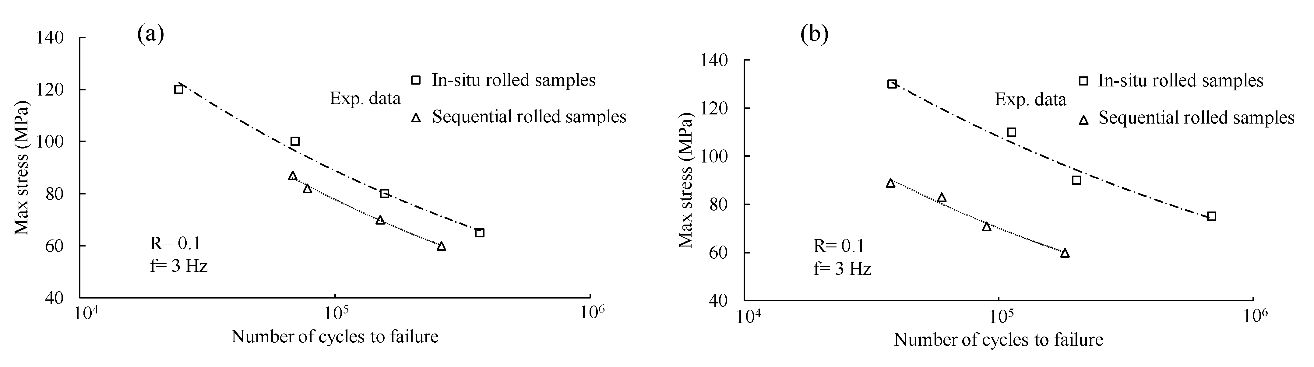
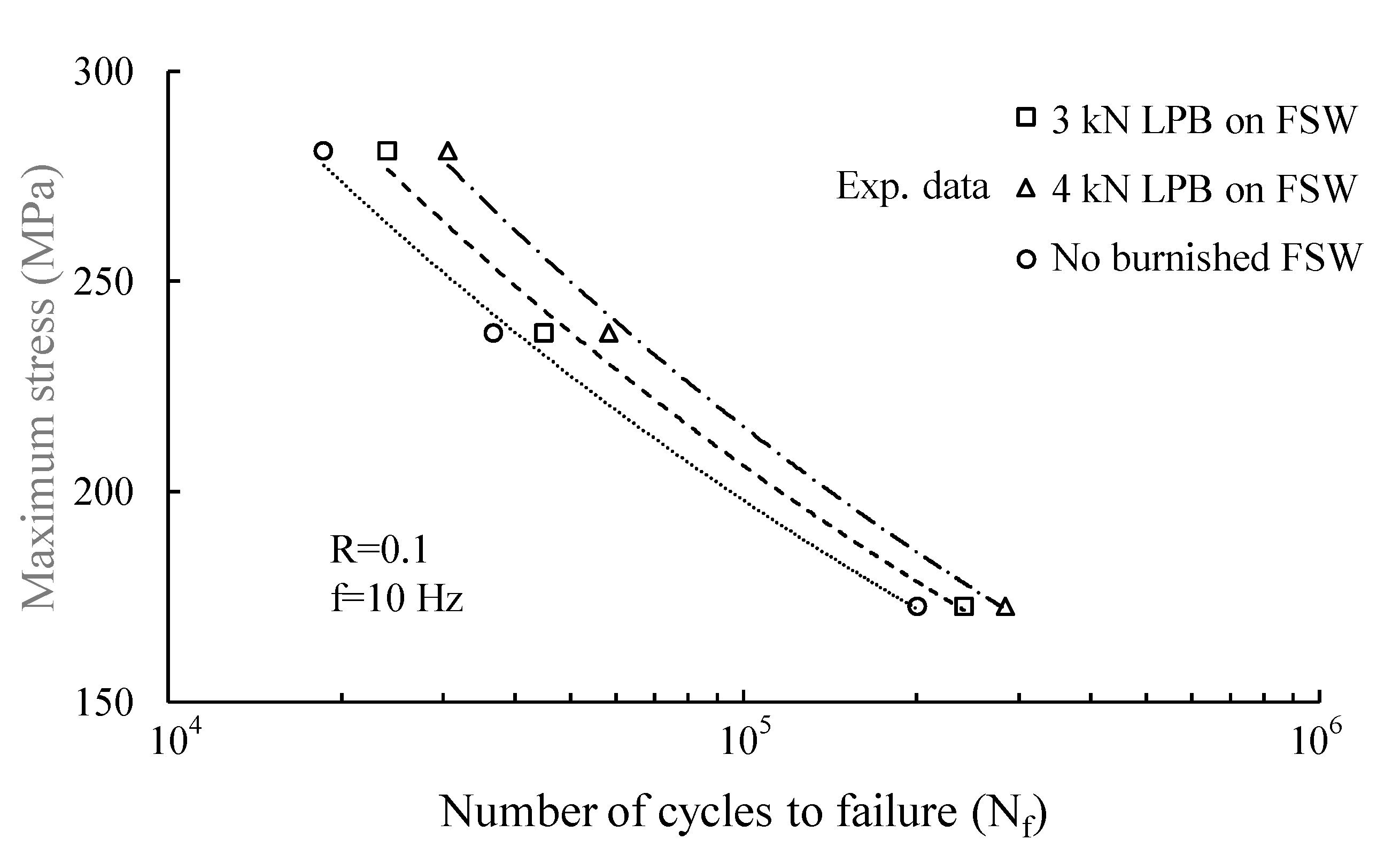
3.3.1. Fatigue Life of Cold Worked Samples

Fatigue tests conducted on several FWS and FSSW aluminum joints revealed how influential the post-processing is. Stress-controlled fatigue tests were conducted at a stress ratio of R = 0.1 to avoid buckling. The FSW fatigue samples were cut from the welded sheets in such a way that cyclic loads were applied perpendicular to the weld seam. The width of the samples was taken to be 25 mm. The lap-shear configuration was used for FSSW fatigue testing. Figure 11, Figure 12, Figure 13, Figure 14 and Figure 15 present stress–fatigue life (S–N) data experimentally obtained for aluminum joints post-processed through in situ/sequential rolling, burnishing, STA heat-treatment, alloying through copper foils and alumina particles. Figure 11 presents the influence of in situ and sequential cold rolled joint samples with different welding tool ball diameters of 6 and 8 mm. The larger tool ball resulted in greater weld region deformation and induced compressive residual stress leading to longer fatigue lives. In situ rolled joint samples achieved longer life cycles to failure than those joints undergoing the sequential rolling process. In situ rolled samples were rolled, while aluminum samples were welded. The fatigue lives of in situ rolled joints was found to be as high as 10 times those of sequentially rolled samples with the tool ball with a diameter of 8 mm (see Figure 11b). This magnitude in life factor reduced to 2 times for the tool ball with a diameter of 6 mm in Figure 11a.
The higher temperature of rolling in in situ rolled joints reduced defects on the weld region over the rolling process. However, micrographs of sequential rolled joints holding worm-hole defects [27] resulted in lower fatigue life of sequentially rolled FSW joints. In contrast, the finer particle dispersion and smaller grain size formed in in situ rolled joints improved the fatigue lives of aluminum joints noticeably.
The low-plasticity burnishing process of friction stir welded joints improved the fatigue lives of aluminum joints by as high as 28% and 57%, respectively, under vertical forces of 3 and 4 kN as compared with those of unburnished joints, as presented in Figure 12.
Joints burnished through the friction stir processing operation with a vertical force of 4 kN demonstrated longer fatigue lives as compared with those burnished with a 3 kN downward force. This is associated with the greater induced compressive residual stresses over the depth of samples burnished with a 4 kN force [19]. It was observed that following the in situ rolling process, the fracture position in rolled samples moved from the HAZ to the SZ. This could be associated with decreased grain size within the HAZ due to the rolling operation [27]. The failure of LPBed samples, on the other hand, took place at different sites. It was observed that the LPB process shifted the failure point about 7 mm toward the base metal.

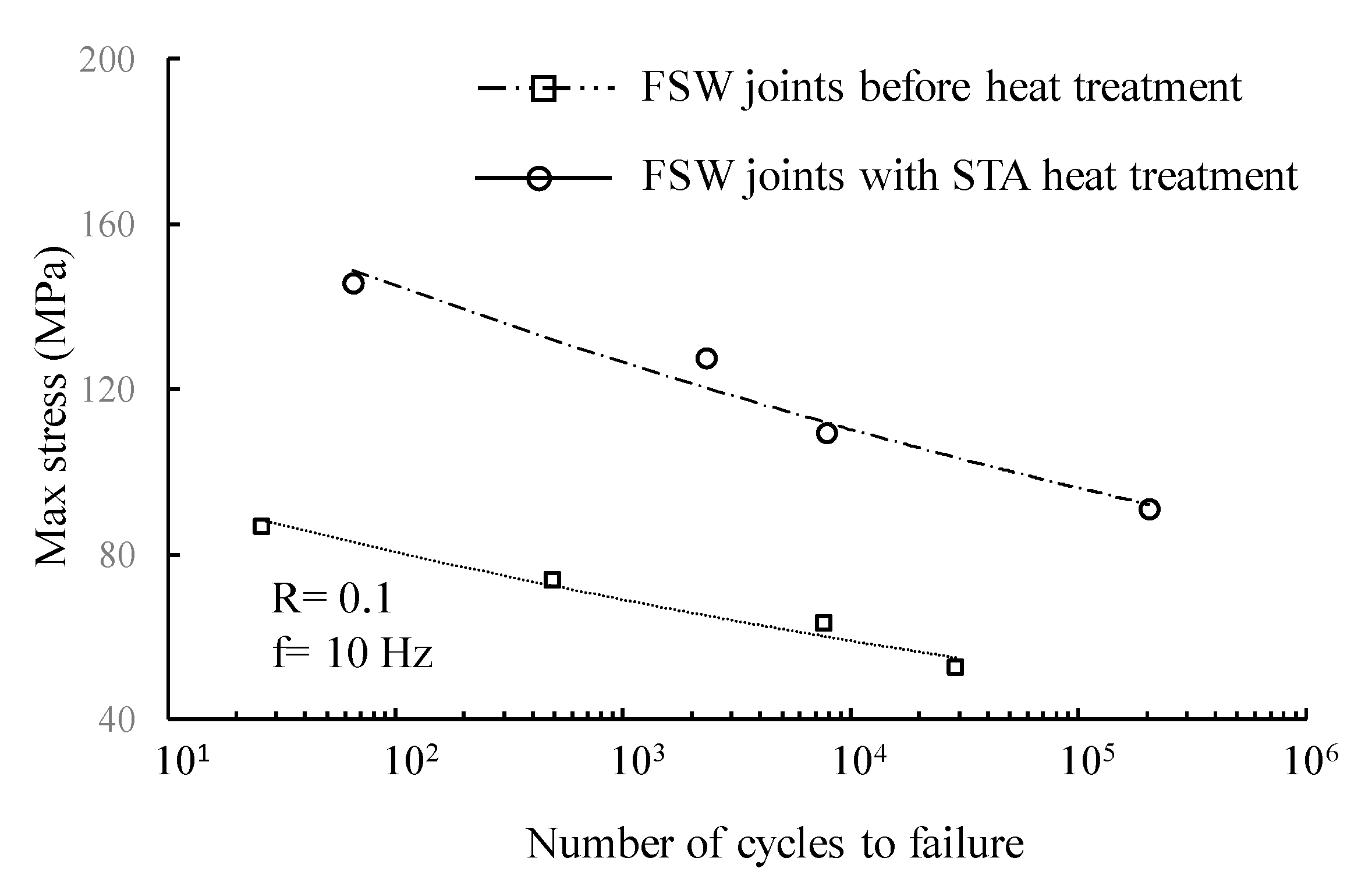
3.3.2. Fatigue Life of Heat-Treated FSW Joints

Figure 13 presents the applied stress versus fatigue life data of Al 6061-T6 FSW joints before and after STA heat-treatment process.
The STA heat treatment improved fatigue life of joints dramatically in Figure 13. The lower fatigue lives of as-welded samples could be attributed to the fact that there were no precipitated second-phase particles in the aluminum matrix to hinder dislocation motion [26].

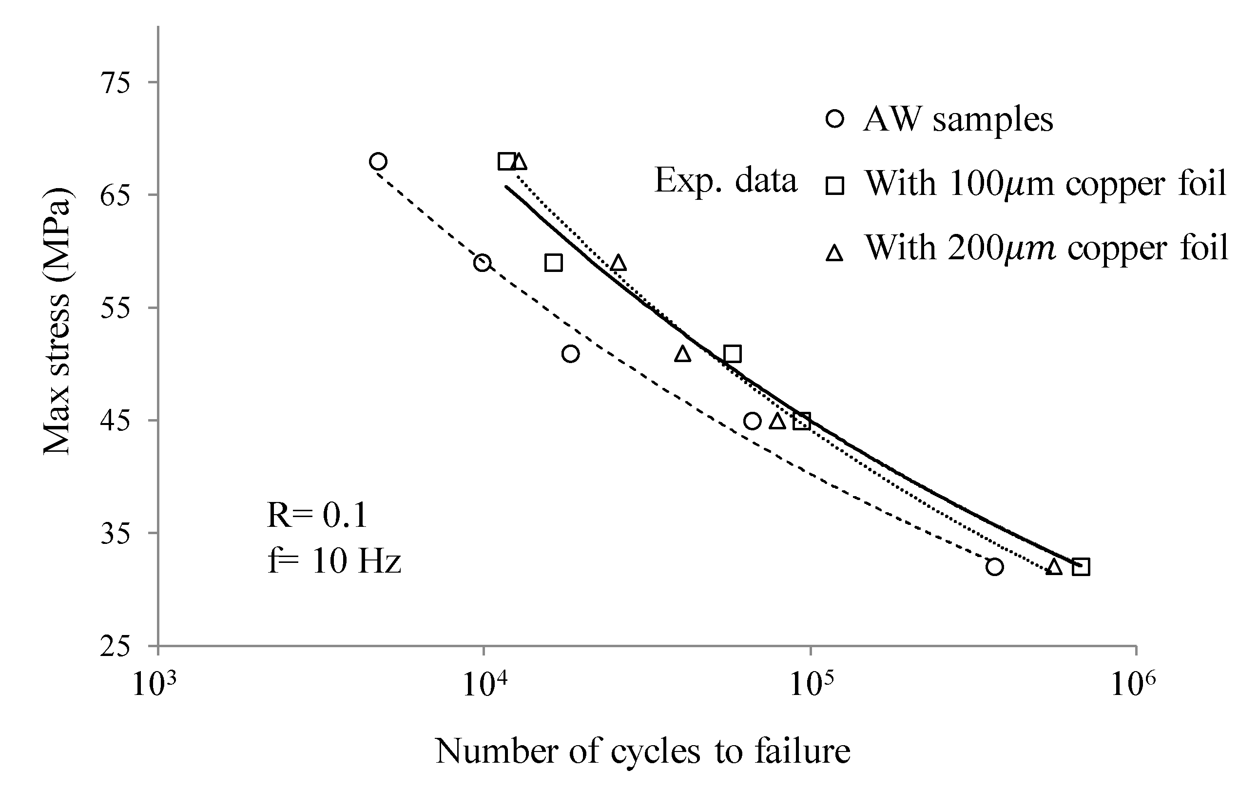
3.3.3. Fatigue Life of Alloyed FSW Joints with Copper Foils

Figure 14 presents fatigue life of Al 1060-H16 FSW joints before and after inserting copper foils between faying surfaces. This figure shows an increase in the fatigue life of joints as copper foils were placed in the SZ of FSW joints. Joint samples with 100 μm-thick copper foil in the SZ resulted in slightly better fatigue lives as compared with those joints with copper foils of 200 μm in thickness. Microstructural observation of weld regions of aluminum joints with 200 μm-thick copper foils revealed the presence of worm-like defects in the weld central region, resulting in a small drop in fatigue life.

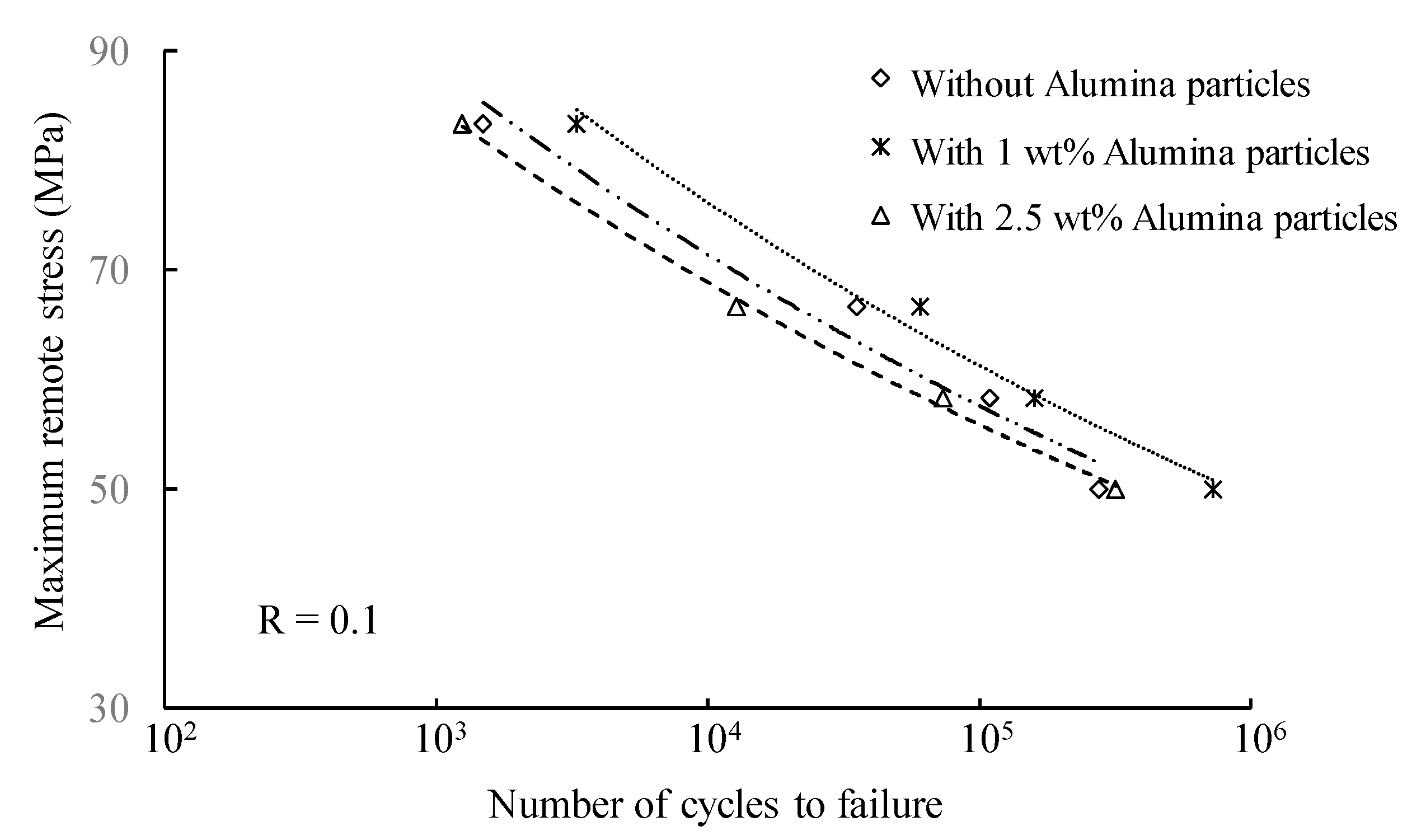
3.3.4. Fatigue Life of Reinforced FSSW Joints with Alumina Particles

Figure 15 presents S–N curves for as-welded FSSW joints and those joints with deposited alumina powder of 1 and 2.5 wt.% in the nugget zone.
Joints with localized MMC containing 1 wt.% alumina particles in the NZ possessed higher fatigue lives as compared with those joints with 2.5 wt.% alumina. The addition of 2.5 wt.% alumina particles in the stirred zone of FSSW joints adversely affected the fatigue strength of joints as compared with as-welded samples. The lack of dispersion of alumina powder in the base metal and the formation of alumina agglomerations in the nugget region hindered the formation of the weld joints, firmly resulting in a drop in the fatigue life of the joint samples.

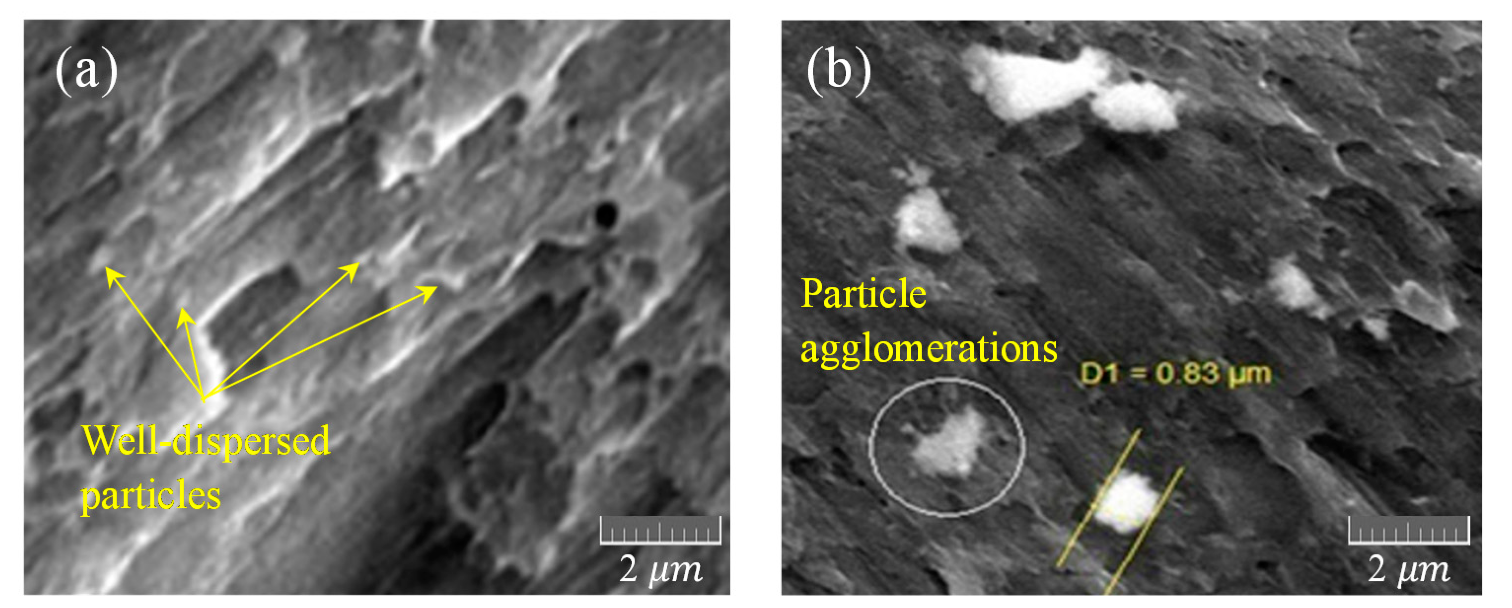
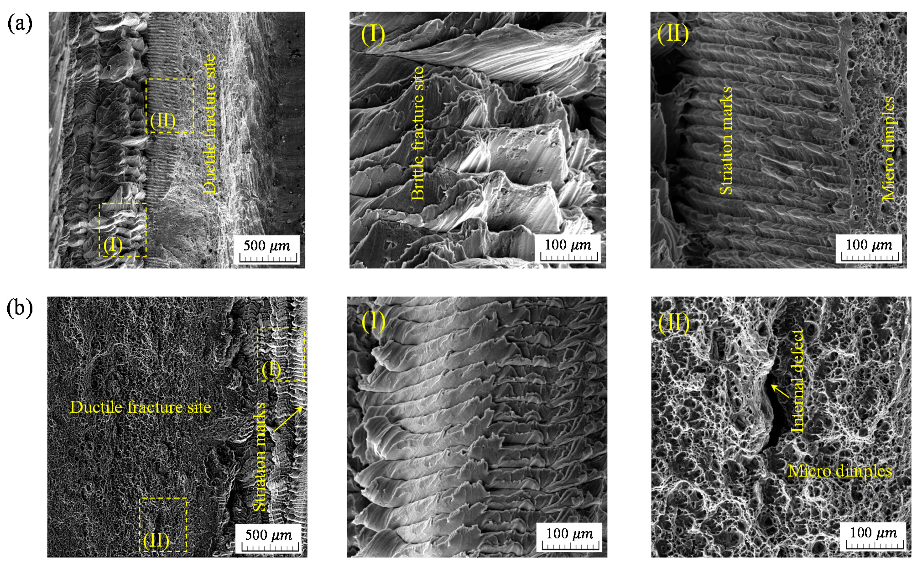
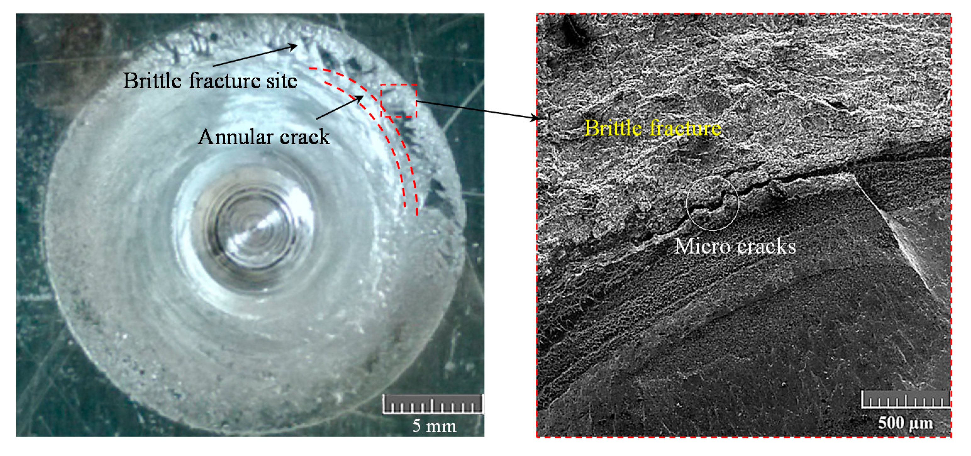
3.4. Fracture Surfaces of Failed Joints

Post-processing operations substantially influenced the microstructure and fracture surface of friction stir welded aluminum joints failed through fatigue loading cycles. Scanning electron microscopy (SEM) was employed to detect features on the fracture surfaces of joints. The fracture surface of in situ rolled joints is shown in Figure 16. Fatigue cracks were nucleated from the interface of HAZ and weld seam in the advancing side of joints then final failure occurred with brittle fracture mode. Figure 16b separates ductile and brittle fracture regions. In situ rolled joints possessed larger areas with dimples (Figure 16c) as compared with those of as-welded joint samples (Figure 16a). No significant difference was seen in the fracture surfaces of the samples rolled with different ball diameters of 6 and 8 mm.
The STA heat treatment altered the features of the fracture surface on joints that failed, as evidenced in Figure 17. Ductile fracture mode and related dimples on the fracture surface of joints post-processed with STA heat-treatment were found to be larger than those of as-welded joints. Heat-treatment of joints uniformly distributed precipitates throughout weld regions. This resulted in a greater fatigue performance. The evidence of second-phase particles Mg2Si over the aging process was detailed in references [31,32]. Fracture surfaces within a ductile mode consisted of dimples, while those with a brittle mode show striation marks on the welded joints in this figure.
Inserting a thin copper foil between the faying surfaces of the aluminum 1060-H16 FSW sheet joints impacted the fatigue response and fracture surface of welded joints. Figure 18a–c illustrate, respectively, the features of the fracture surface of as-welded FSW joints and joints alloyed with thin copper foils with thicknesses of 100 and 200 μm. The size of the area with a brittle fracture surface on the as-welded FSW joint appeared to be larger than that of the joint alloyed with copper foil. This led to a reduction in energy absorption during loading cycles and consequently shorter fatigue lives as compared with those joints with 100 μm-thick foil within the SZ. Inserting thicker copper foil with a thickness of 200 μm, however, caused a separation of copper particles from the aluminum matrix, leaving a porous microstructure, resulting in a slight reduction in fatigue strength. Figure 18a shows that in the absence of copper foil, the fracture surface of aluminum joint consists of a brittle fracture mode with vertical striations and marks. Insertion of 100 μm-thick copper foil between the faying surfaces diffused within both surfaces and alloyed the joint within SZ. This resulted in a ductile fracture mode with dimples appearing on the fracture surface. As copper foil increased in thickness to 200 μm, the fracture surface deviated to ductile and porous fracture features.
Inclusion of alumina particles in the NZ affected the cracking manner of FSSW joints undergoing fatigue loading cycles. FSSW joints containing 1 wt.% alumina particles experienced circumferential cracks followed by either a crack propagation along sheet joints or partial nugget pull-out and lap-shear failure. The samples containing 2.5 wt.% alumina particles experienced lap-shear failure or nugget pull-out in the upper sheet depending on the applied load level. Figure 19 depicts a typical lap-shear failure caused by propagating annular cracks followed by a brittle fracture.
The fatigue of joints fabricated through the friction stir welding operation is highly influenced by post-processing and treatments. While cold rolling and burnishing of welded joints can improve the mechanical properties and fatigue of joints, the sequence of rolling, temperature during the rolling operation, welding tool and geometry, and the magnitude of loads applied on the weld seam during the rolling and burnishing operations are influential parameters. The in situ rolling process generated large areas of ductile fracture mode and refined grains within the HAZ of FSW aluminum joints. Both rolling and burnishing induced compressive residual stresses within the weld region or reduced tensile residual stresses due to welding operation, resulting in promoted durability of joints against fatigue failure. A larger ball diameter in this post-processing method further improved the rolling pressure and contact surface, resulting in an efficient material flow in the process. The LPB or sequentially rolling techniques were conducted on the top surfaces of the weld samples after welding operation and cooling down, causing less dynamic recrystallization and grain refinement as compared with those of in situ rolled samples. A phase delay between welding and rolling/burnishing processes not only generated defects on the microstructure; it also adversely affected the fatigue strength of the joints. It is believed that the induced compressive residual stresses due to the LPB operation can vary over the depth of FSW samples, resulting in a delay in fatigue crack nucleation. The magnitude of transverse residual stresses perpendicular to the weld seam was found to be insignificant by Hassanifard et al. [19] and De Giorgi et al. [33]. These stresses, however, altered during loading cycles and affected fatigue strength noticeably [19]. Sun et al. [34] showed that the residual stresses induced by the FSW operation, especially those appeared in the upper surface over cyclic process, impacted fatigue and cracking. The STA heat treatment as a post-processing step on the aluminum welded joint noticeably reduced tensile residual stresses due to the welding process and formed a more uniform microstructure within the HAZ. The PWHT has developed cleavage facets on the tensile fracture surface, leading to an improvement in fatigue durability of the welded joints. Aluminum joints were alloyed with thin copper foils inserted between the faying surfaces of aluminum sheet joints during FSW process resulting in a formation of ductile dimples in the SZ. The massive formation of ductile dimples within the SZ region was taken as an index of fatigue strength of joints. Inserting thicker copper foils in the SZ, however, hindered the further solid solution of copper particles in aluminum matrix, resulting in the formation of larger unsolved particles of copper and brittle intermetallic in the SZ. This is related to the solubility limit of copper substance in aluminum matrix [28]. A well-dispersed and sufficient amount of alumina particles within NZ of FSSW joints further boosted the tensile and fatigue resistances of aluminum joints. However, an excess of alumina particles tends to form agglomeration. An extra amount of 2.5 wt.% alumina particles resulted in a significant reduction in the ductility and fatigue strength of Al 7075-T6 joints.
The choice of post-processing technique to improve the durability and fatigue life of FSW joints is of prime concern in the design and manufacturing of machinery parts and structures. The inclusion of these techniques is essential for the safe design of load-bearing components in service. While the current study examined the effect of various post-processing techniques and treatments on fatigue performance of aluminum joints, the authors believe that more testing and experiments are required to comprehensively address influential parameters on fatigue response of FSW aluminum joints.

4. Conclusions

Post-processing techniques such as the in situ/sequential rolling process, the LPB operation, STA heat treatment, inserting thin copper foils between the faying surfaces of FSW sheet joins, and finally creating MMC through depositing alumina powder into the nugget zone of FSSW joints were studied to evaluate the microstructure and fatigue life of FSW/FSSW joints. Post-processing and treatments resulted in an increase in fatigue lives of joint samples. Examination of fracture surface of joint samples failed under fatigue cycles revealed that joints undergoing in situ rolling process, the STA heat treatment, and inserted with copper foils between the faying surfaces of the sheet joins during FSW operation demonstrated larger areas of a ductile mode of fracture with the related dimples on the fracture surfaces, leading to improved fatigue strength as compared with as-welded samples. Agglomeration of the particles in the case of FSSW joints containing 2.5 wt.% alumina was the main reason for thew smaller weld area, resulting in shorter fatigue lives. Adopting a set of optimized process parameters and modifying FSW tool geometry noticeably influenced the mechanical properties and efficiency of welded joints. The fatigue lives of the FSW/FSSW joints were further enhanced through post-processing techniques and treatments. These techniques enable engineers to design joints with greater strength and durability. The choice of post-processing and treatments on the welded joints highly influence the design safety, durability, and fatigue life of aluminum joints subjected to cyclic loading conditions.

Author Contributions

Conceptualization, methodology, validation, investigation, data analysis, writing—review and editing, S.H. and A.V.-F.; supervision; A.V.-F.; funding acquisition, A.V.-F. All authors have read and agreed to the published version of the manuscript.

Funding

This research was funded by NSERC, grant number RGPIN-2016-04957.

Data Availability Statement

The data presented in this study are available on request from the corresponding author. The data are not publicly available due to its complex nature.

Acknowledgments

Authors acknowledge financial supports through Natural Sciences and Engineering Research Council (NSERC) of Canada. Special thanks to A. Ghiasvand; A. Nabavi-Kivi; H. Mousavi; H.A. Reyhani; H. Alipour M. Mohammadpour; H.A. Rashid; for materials testing and experiments.

Conflicts of Interest

The authors declare no conflict of interest. The funder had no role in the design of the study; in the collection, analyses, or interpretation of data; in the writing of the manuscript, or in the decision to publish the results.

References

  1. Thomas, W.; Nicholas, E.; Needham, J.; Murch, M.; Temple-smith, P.; Dawes, C. Friction Welding. US Patent No. 5460317, 1997. [Google Scholar]
  2. Chang, W.S.; Chun, C.K.; Kim, H.J.; Cho, H.J.; Kim, T.K. Mechanical and micro structural properties of friction spot joined 5052 and 6111 Al Alloys. J. Mater. Sci. Forum 2008, 580–582, 435–438. [Google Scholar] [CrossRef]
  3. Gerlich, A.; Su, P.; North, A.; Bendzsak, T.H. Intermixing in dissimilar friction stir spot welds. J Metall. Mater. Trans. A 2007, 38, 584–595. [Google Scholar]
  4. Enami, M.; Farahani, M.; Farhang, M. Novel study on keyhole less friction stir spot welding of Al 2024 reinforced with alumina nanopowder. Int. J. Adv. Manuf. Technol. 2019, 101, 3093–3106. [Google Scholar] [CrossRef]
  5. Hong, S.T.; Das, H.; Oh, H.S.; Al Nasim, M.; Chun, D.M. Combination of nano-particle deposition system and friction stir spot welding for fabrication of carbon/aluminum metal matrix composite joints of dissimilar aluminum alloys. CIRP Ann. Manuf. Technol. 2017, 66, 261–264. [Google Scholar] [CrossRef]
  6. Bahrami, M.; Helmi, N.; Dehghani, K.; Givi, M.K. Exploring the effects of SiC reinforcement incorporation on mechanical properties of friction stir welded 7075 aluminum alloy: Fatigue life, impact energy, tensile strength. Mater. Sci. Eng. A 2014, 595, 173–178. [Google Scholar] [CrossRef]
  7. Lenin, A.W.A.; Periyasamy, N.; Lincy, G. Influence of interlayer thickness (Zn) on the properties of Al 7020 FSW joints. Mater. Res. 2016, 19, 817–823. [Google Scholar] [CrossRef] [Green Version]
  8. Ren, S.R.; Ma, Z.Y.; Chen, L.Q. Effect of welding parameters on tensile properties and fracture behavior of friction stir welded Al–Mg–Si alloy. Scr. Mater. 2007, 56, 69–72. [Google Scholar] [CrossRef]
  9. Premkumar, P.; Ruskin, B.A.; Yogesh Krishnan, P.R. Influence of tool pin profile in underwater friction stir welding of aluminum 6061 alloy, IOP Conference Series: Materials Science and Engineering. In Proceedings of the International Conference on Technological Advancements in Materials, Design, Manufacturing and Energy Sectors (ICTAMDMES’20), Chennai, India, 20–21 February 2020; Volume 923. [Google Scholar]
  10. Babu, S.; Elangovan, K.; Balasubramanian, V.; Balasubramanian, M. Optimizing friction stir welding parameters to maximize tensile strength of AA2219 aluminum alloy joints. Met. Mater. Int. 2009, 15, 321–330. [Google Scholar] [CrossRef]
  11. Lombard, H.; Hattingh, D.G.; Steuwer, A.; James, M.N. Optimising FSW process parameters to minimise defects and maximise fatigue life in 5083-H321 aluminium alloy. Eng. Fract. Mech. 2008, 75, 341–354. [Google Scholar] [CrossRef]
  12. Palanivel, R.; Koshy Mathews, P.; Murugan, N.; Dinaharan, I. Effect of tool rotational speed and pin profile on microstructure and tensile strength of dissimilar friction stir welded AA5083-H111 and AA6351-T6 aluminum alloys. Mater. Des. 2012, 40, 7–16. [Google Scholar] [CrossRef]
  13. Ugender, S.; Kumar, A.; Reddy, A.S. Experimental investigation of tool geometry on mechanical properties of friction stir welding of AA 2014 aluminium alloy. Procedia Mater. Sci. 2014, 5, 824–831. [Google Scholar] [CrossRef]
  14. Su, H.; Wu, C.S.; Bachmann, M.; Rethmeier, M. Numerical modeling for the effect of pin profiles on thermal and material flow characteristics in friction stir welding. Mater. Des. 2015, 77, 114–125. [Google Scholar] [CrossRef]
  15. Elangovan, K.; Balasubramanian, V.; Valliappan, M. Influences of tool pin profile and axial force on the formation of friction stir processing zone in AA6061 aluminium alloy. Int. J. Adv. Manuf. Technol. 2008, 38, 285–295. [Google Scholar] [CrossRef]
  16. Yuvaraj, K.; Varthanan, P.A.; Haribabu, L.; Madhubalan, R.; Boopathiraja, K. Optimization of FSW tool parameters for joining dissimilar AA7075-T651 and AA6061 aluminum alloys using Taguchi Technique. Mater. Today: Proc. 2020, 45, 919–925. [Google Scholar]
  17. Ghiasvand, A.; Hassanifard, S.; Saadi, S.; Varvani-Farahani, A. Tensile properties and microstructural features of friction stir welded Al 6061 joints fabricated by various dual-pin tool shapes. Sci. Technol. Weld. Join. 2021, 26, 493–502. [Google Scholar] [CrossRef]
  18. Hassanifard, S.; Mohammadpour, M.; Rashid, H.A. A novel method for improving fatigue life of friction stir spot welded joints using localized plasticity. Mater. Des. 2014, 53, 962–971. [Google Scholar] [CrossRef]
  19. Hassanifard, S.; Mousavi, H.; Varvani-Farahani, A. The influence of low-plasticity burnishing process on the fatigue life of friction-stir-processed Al 7075-T6 samples. Fatigue Fract. Eng. Mater. Struct. 2019, 42, 764–772. [Google Scholar] [CrossRef]
  20. Jayaraman, N.; Prevéy, P.S.; Mahoney, M. Fatigue life improvement of an aluminum alloy FSW with low plasticity burnishing. In Proceedings of the 132nd TMS Annual Meeting, San Diego, CA, USA, 2 March 2003. [Google Scholar]
  21. Huang, Y.; Wan, L.; Lv, S.; Zhang, J.; Fu, G. In situ rolling friction stir welding for joining AA2219. Mater. Des. 2013, 50, 810–816. [Google Scholar] [CrossRef]
  22. Prevéy, P.S.; Jayaraman, N.; Cammett, J. Overview of low plasticity burnishing for mitigation of fatigue damage mechanisms. In Proceedings of the 9th International Conference for Shot Peening, Paris, France, 6–9 September 2005. [Google Scholar]
  23. Rodríguez, A.; Calleja, A.; López de Lacalle, L.N.; Pereira, O.; González, H.; Urbikain, G.; Laye, J. Burnishing of FSW Aluminum Al–Cu–Li components. Metals 2019, 9, 260. [Google Scholar] [CrossRef] [Green Version]
  24. Ravi, S.; Balasubramanian, V.; Nasser, S.N. Influences of post weld heat treatment on fatigue life prediction of strength mis-matched HSLA steel welds. Int. J. Fatigue 2005, 27, 547–553. [Google Scholar] [CrossRef]
  25. Edwards, P.; Ramulu, M. Fatigue performance of friction stir welded Ti–6Al–4V subjected to various post weld heat treatment temperatures. Int. J. Fatigue 2015, 75, 19–27. [Google Scholar] [CrossRef]
  26. Hassanifard, S.; Nabavi-Kivi, A.; Ghiasvand, A.; Varvani-Farahani, A. Monotonic and fatigue response of heat-treated friction stir welded Al 6061-T6 joints: Testing and characterization. Mater. Perform. Charact. 2021, 10, 353–369. [Google Scholar]
  27. Hassanifard, S.; Reyhani, H.A.; Nabavi-Kivi, A.; Varvani-Farahani, A. An experimental study of rolled friction-stir-welded aluminum 6061-T6 joints subjected to static and fatigue loading conditions. J. Mater. Eng. Perform. 2020, 29, 4493–4505. [Google Scholar] [CrossRef]
  28. Hassanifard, S.; Alipour, H.; Ghiasvand, A.; Varvani-Farahani, A. Fatigue response of friction stir welded joints of Al 6061 in the absence and presence of inserted copper foils in the butt weld. J. Manuf. Process. 2021, 64, 1–9. [Google Scholar] [CrossRef]
  29. Shen, Z.; Ding, Y.; Chen, J.; Fu, L.; Liu, X.C.; Chen, H.; Guo, W.; Gerlich, A.P. Microstructure, static and fatigue properties of refill friction stir spot welded 7075-T6 aluminium alloy using a modified tool. Sci. Technol. Weld. Join. 2019, 24, 587–600. [Google Scholar] [CrossRef]
  30. Rosendo, T.; Tier, M.; Mazzaferro, J.; Mazzaferro, C.; Strohaecker, T.R.; Dos Santos, J.F. Mechanical performance of AA6181 refill friction spot welds under lap shear tensile loading. Fatigue Fract. Eng. Mater. Struct. 2015, 38, 1443–1455. [Google Scholar] [CrossRef]
  31. Fadaeifard, F.; Pakmanesh, M.R.; Esfahani, M.S.; Matori, K.A.; Chicot, D. Nanoindentation analysis of friction stir welded 6061-T6 Al alloy in as-weld and post weld heat treatment. Phys. Met. Metallogr. 2019, 120, 483–491. [Google Scholar] [CrossRef]
  32. Baghdadi, A.H.; Rajabi, A.; Selamat, N.F.; Sajuri, Z.; Omar, M.Z. Effect of post-weld heat treatment on the mechanical behavior and dislocation density of friction stir welded Al6061. Mater. Sci. Eng. A 2019, 754, 728–734. [Google Scholar] [CrossRef]
  33. De Giorgi, M.; Scialpi, A.; Panella, F.W.; De Filippis, L.A.C. Effect of shoulder geometry on residual stress and fatigue properties of AA6082 fsw joints. J. Mech. Sci. Technol. 2009, 23, 26–35. [Google Scholar] [CrossRef]
  34. Sun, G.; Wei, X.; Niu, J.; Shang, D.; Chen, S. Influence of residual stress on fatigue weak areas and simulation analysis on fatigue properties based on continuous performance of FSW joints. Metals 2019, 9, 284. [Google Scholar] [CrossRef] [Green Version]
Figure 1. (a) Rolling tool and schematic view of tool-joint; (b) top view of the rolled joint and its cross-section.
Jmmp 05 00093 g001
Figure 2. (a) The LPB tool and set up; (b) burnished paths on the Al 7075-T6 welded joint.
Jmmp 05 00093 g002
Figure 3. The STA treatment performed on FSW joints.
Jmmp 05 00093 g003
Figure 4. Schematic views of the alloying process through inserting thin copper foils between the faying surfaces of aluminum sheet joints.
Jmmp 05 00093 g004
Figure 5. (a) The process of creating MMC through adding alumina powder in the weld nugget of FSSW joints; (b) a typical FSSW joint sample with the A–A cross-sectional view.
Jmmp 05 00093 g005
Figure 6. Tensile stress–strain curves for Al 10160-H16, Al 6061-T6 and Al 7075-T6 examined in this study: (a) base-metal; (b) in situ vs. sequentially rolled joints; (c) LPB vs. non-burnished joints; (d) heat-treated vs. non-heat-treated joints; (e) joints with Cu foil vs. without Cu foil; (f) joints with alumina and without alumina powder.
Jmmp 05 00093 g006
Figure 7. Microstructures within the HAZ of welded joints for: (a) the as-welded sample; (b) the in situ rolled sample with 6 mm ball diameter; (c) the in situ rolled sample with 8 mm ball diameter.
Jmmp 05 00093 g007
Figure 8. Grain orientation in a burnished sample within the HAZ near the top surface of the sample.
Jmmp 05 00093 g008
Figure 9. Microstructures of the HAZ for: (a) the as-welded joint; (b) the STA heat-treated joint.
Jmmp 05 00093 g009
Figure 10. SEM images of distribution of alumina powder in aluminum 7075-T6 after FSSW procedure in: (a) the joint containing 1 wt.% alumina particles; (b) the joint with 2.5 wt.% alumina particles.
Jmmp 05 00093 g010
Figure 11. S–N curves of in situ rolled (IR) and sequential rolled (SR) for FSW joints: (a) ball size of d = 6 mm; (b) ball size of d = 8 mm.
Jmmp 05 00093 g011
Figure 12. S–N curves of LPBed joints and their comparison with that of friction stir processed samples.
Jmmp 05 00093 g012
Figure 13. Stress–fatigue life data of heat-treated FSW samples and their comparison with those of as-welded joints.
Jmmp 05 00093 g013
Figure 14. S–N curves of alloyed FSW samples with copper foil in the SZ and their comparison with that of as-welded samples.
Jmmp 05 00093 g014
Figure 15. S–N curves of MMC FSSW samples and their comparison with that of as-welded samples.
Jmmp 05 00093 g015
Figure 16. SEM images of fracture surface: (a) as-welded FSW samples; (b,c) in situ rolled FSW samples.
Jmmp 05 00093 g016
Figure 17. SEM images of fracture surface: (a) as-welded FSW joint sample; (b) STA heat-treated FSW joint sample.
Jmmp 05 00093 g017
Figure 18. SEM images of fracture surface: (a) as-welded Al 1060-H16 FSW sample; (b) FSW sample with 100 μm-thick copper foil in the SZ; (c) FSW sample with 200 μm-thick copper foil in the SZ.
Jmmp 05 00093 g018
Figure 19. A typical lap-shear failure in the FSSW joint.
Jmmp 05 00093 g019
Table 1. Process parameters for friction stir welding operations on aluminum joint samples.
Processing TypeMaterialWeld TypeSheet Thickness (mm)RS (RPM)LTS (mm/s)Tilt AngleShoulder Diameter (mm)Pin
Diameter (mm)
Pin Length (mm)
Cold workingIn situ/sequential rollingAl 6061-T6FSW514000.6-1862.6
LPB processingAl 7075-T6FSW514000.5–21862
Heat treatmentPWHTAl 6061-T6FSW514001.61864
Alloying/MMCInserting Cu foils in the faying surfaceAl 1060-H16FSW514000.62.5°206–8 cone-shaped4.8
Adding alumina powderAl 7075-T6FSSW21100--1862.5
Table 2. Tensile test results of FSW/FSSW samples before and after post-processing.
Joint SamplesUTS (MPa)Elongation (%)
In situ rolled sample with 6 mm balls1384.8
In situ rolled sample with 8 mm balls1555.9
Sequential rolled sample with 6 mm balls1212.7
Sequential rolled sample with 8 mm balls1152.4
As-welded sample1102.9
LPBed sample with 3 kN force3738.5
LPBed sample with 4 kN force3759.0
FSW sample before LPB process3698.9
STA heat-treated sample1823.2
As-welded sample1052.5
Alloyed sample with 100 μm-thick Cu foil1013.2
Alloyed sample with 200 μm-thick Cu foil882.3
As-welded sample681.9
MMC sample with 1 wt.% alumina powder1699.8
MMC sample with 2.5 wt.% alumina powder1393.9
FSSW sample without alumina powder1437.0
Publisher’s Note: MDPI stays neutral with regard to jurisdictional claims in published maps and institutional affiliations.

