1. Introduction
Shape memory alloys (SMAs) such as NiTi possess the capability to retrieve their original shape despite a significant degree of deformation under temperature and stress conditions. Hence, they are being used extensively as a functional material in engineering and medical applications [
1,
2]. The properties of SMAs, such as super-elasticity (SE) or shape memory effect (SM), are closely associated with the characteristics of martensitic transformation and the mechanical response of two distinct phases, martensite, and austenite [
3,
4,
5,
6]. Due to recent progress in modern material technology, the additive manufacturing (AM) technique is an effective way to fabricate complicated NiTi geometries with specified porosity, uniform composition, and suitable characteristics, in contrast to the difficulties affiliated with the traditional manufacturing methods [
7]. Among the various AM techniques, laser powder bed fusion (LPBF) is one of the most preferable. The LPBF process starts with spreading a thin layer of NiTi powder; then, a high-power density laser is used to melt and fuse the metallic powder. This cycle is repeated layer-by-layer with the help of a spreader and adjustable build platform until a complete part has been fabricated [
8].
Desirable characteristics of NiTi, such as good biocompatibility, low stiffness, excellent corrosion resistance, high wear resistance, high ductility, and strength properties are major concerns of interest [
9,
10,
11,
12,
13]. On the other hand, time-dependent plastic deformation and the creep mechanism in NiTi alloys have been explored by a few researchers [
14,
15]. The progressive deformation of material at constant stress or creep is a major challenge because it reduces the service life and efficiency of different components in many structural applications [
16,
17]. Although extensive investigations have been performed to evaluate the macroscopic mechanical properties of NiTi, characterization at small-scale volumes is very crucial because of its higher use in small-scale applications such as micro-electro-mechanical systems, medical stents, guide wires, or micro-actuators [
2,
18,
19]. Therefore, investigating the small-scale deformation behavior and creep mechanism of NiTi alloy is an extremely important issue to evaluate the lifetime or durability of advanced small-scale structures.
In general, the creep behavior of a material is characterized with the help of simple uniaxial tension or compression tests, but it cannot be adopted to small-scale structures. Although the conventional/classical creep tests are very time-consuming, the depth-sensing indentation testing approach (i.e., micro/nanoindentation) is regarded as a dependable, convenient, and non-destructive testing methodology to evaluate the creep behavior of a material [
20,
21,
22]. Through indentation creep tests, small-scale creep properties and their local changes can be evaluated, which are applicable to micro- or nanoscale structures as well as comparatively large components as in the weld-heat-affected area where complicated microstructure gradients exist [
23]. The indentation creep is specified as the relative change of the indentation depth while the applied load stands constant. During the indentation creep test, the indenter retains its peak load through a specific period under a well-controlled state, and alterations in indentation depth (size) are monitored as a function of time [
24,
25]. Indentation creep was investigated by some researchers at high temperatures. Sadeghilaridjani et al. [
17] assessed the nanoindentation creep performance of two multi-principal element alloys, CoCrNi and CoCrFeMnNi, subjected to a temperature range of 298 K to 573 K under static and dynamic loads up to 1000 mN. The stress exponent of CoCrNi was found to decrease with a rise in temperature because of thermally activated dislocations; in contrast, the stress exponent was not sensitive to temperature because of dislocation glide-dominated deformation. Moreover, the stress exponent demonstrated a rise with the escalation of load. The phenomenon was ascribed to the greater generation of dislocation rate and their entanglement at the greater path. Additionally, Zhang et al. [
26] evaluated the time-dependent plastic deformation properties of IN-617 at higher temperatures of 400 °C and 800 °C through the nanoindentation technique. The creep mechanism was dominated by a dislocation climb that conformed to the microstructural observation. Stress exponent values were consistent with the literature, and indentation depth was found to be independent of the surface oxidation effect.
In this context, Kaur et al. [
27] investigated the room temperature nanoindentation creep of nano-grained NiTiW shape memory alloy thin films and interpreted the creep mechanism utilizing grain boundary mediated dislocation dynamics. In addition, Choudhary et al. [
28] carried out indentation creep tests to quantify the damping performance of NiTi/PZT thin film heterostructures at room temperature, and found a high damping capacity because of superelasticity in NiTi and strong piezoelectric effect in the PZT layer. Moreover, He et al. [
29] evaluated the room-temperature indentation creep behavior of a solution-treated 60 NiTi alloy manufactured by the hot isostatic pressing method. They reported that the dislocation movement is mainly responsible for the creep mechanism. However, the indentation creep response and the associated controlling mechanisms of additively manufactured NiTi alloy have not yet been explored. Therefore, the goal of this study is to investigate the constant load–hold indentation creep behavior of additive manufactured NiTi (in the printed and heat-treated states) and to make a comparison with the cast counter. Subsequently, associated quantitative measurements of creep parameters (creep displacement, creep rate, and creep stress exponent) and the correlation among the experimental and creep parameters, have been analyzed, discussed, and reported. The findings of this study will provide a baseline to study and compare the creep behavior of additively manufactured NiTi alloy with cast alloys in terms of heat-treated conditions.
2. Concept of Indentation Creep
Nanoindentation systems can be employed to evaluate the time-dependent mechanical responses through assessing the indentation load–displacement (
P-h) curves without hardness impression observation in a systematic way. The stress distribution beneath the Berkovich tip is intricate (high triaxial stress in the magnitude of GPa) compared to conventional creep tests, which results in a creep deformation of materials in ambient conditions below the recrystallization temperature. The high shear stress value under the indenter [
30] at a very small displacement facilitates overcoming the yield stress in a particular material. Between a variety of indentation creep testing methods, the constant load–hold technique is one of the most widely used [
31] because of its similarity with traditional uniaxial creep tests in terms of loading and holding sequences.
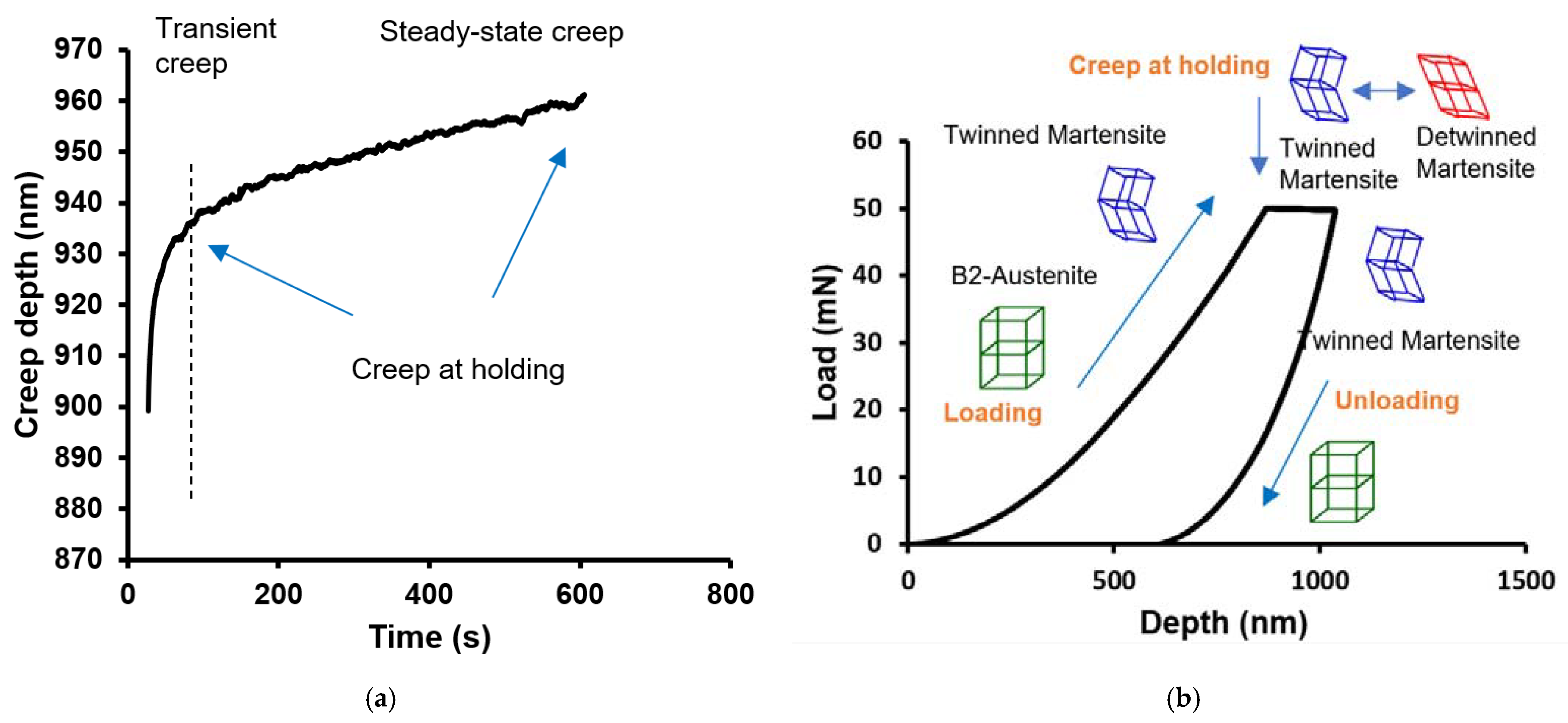
In the constant load–hold indentation creep test, after the loading stage, an extended dwell time is maintained at the maximum load and unloaded afterward (
Figure 1b). The stages of indentation creep are shown in
Figure 1a, where transient creep occurs at the time of loading and steady-state creep is achieved at the holding period. During the holding time, the increase in the penetration depth versus force and time is monitored and measured. Kaur et al. [
27] performed room temperature nanoindentation creep of nanograined NiTiW SMA thin films, and demonstrated that when the load was applied, the sample (preferably in the austenite phase) started transforming into martensite. On reaching a maximum load of 50 mN, austenite became fully martensite, as shown in
Figure 1b. Upon reaching the maximum load, samples became fully martensitic; the creep behavior has been studied during this period. At the holding time, the creep behavior is accompanied by the deformation of martensite to detwinned martensite when a permanent deformation takes place.
From the displacement change recorded during holding at the peak load, the change in stress during dwell time can be estimated. To evaluate the rate-dependent deformation behavior of material through the indentation method, an indispensable part is the quantification of the variation of indentation displacement as a function of time. In this study, the experimental data of the holding phase have been used to assess the creep behavior. The indentation stress can be defined as [
22]:
Here, P is the indentation load, h is the instantaneous contact depth, and R is the indenter tip radius due to blunting at the tip, which was 200 nm for the Berkovich indenter used in this study.
For Berkovich tips, the indentation strain rate can be written as [
22]:
Here,
is the indentation strain rate, h is the instantaneous indentation depth,
is the rate of indentation depth,
is the loading rate, and
P is the indentation load. The displacement rate is
at a constant creep, and the load can be obtained by fitting the displacement–time curve using an empirical equation [
32]:
where
h0 and
t0 are the initial depth and time during the creep period, respectively, and
a,
b, and
k are fitting constants.
The strain rate sensitivity of the flow stress is defined as:
With the “
m” value, apparent activation volume (
V*) can be obtained, which is the volume swept by dislocation from a ground equilibrium state to an activated state after deformation. The equation of the apparent activation volume is given as:
where
k is the Boltzmann constant, and
MT is the Taylor factor equal to
, and
σind is the indentation stress.
The stress exponent denoting creep mechanism (
n) is the slope of the double logarithmic strain rate–stress curve at isothermal conditions and is defined as [
32]:
3. Experimental Procedure
Ni
50.8Ti
49.2 (at.%) ingots obtained from Nitinol Devices and Components, Inc. (Fremont, CA, USA) were cut via an electro-discharge machine (EDM) to generate specimens with dimensions of 10 mm × 10 mm × 8 mm. Afterwards, to generate NiTi powder from the ingots, an electrode induction melting inert gas atomization process with TLS Technique GmbH (Bitterfeld, Germany) was employed. To fabricate the printed specimens from NiTi powder, a Phenix PXM (3D Systems, Wilsonville, OR, USA) LPBF machine equipped with a 300 W Ytterbium fiber laser was used. Two samples were fabricated for heat-treatment purposes. While fabricating the parts, the oxygen level inside the chamber was set to 1000 ppm to minimize impurities in the final components. The LPBF process parameters used for the fabrication of the samples are presented in
Table 1.
The Lindberg/Blue M Mini-Mite
TM (Model: TF55035A-1, Thermo Fisher Scientific, Waltham, MA, USA) tube furnace was used to heat-treat both the cast and printed samples. Before every heat treatment, the instrument was purged through Argon gas at a 90 cubic centimeters per minute (cm
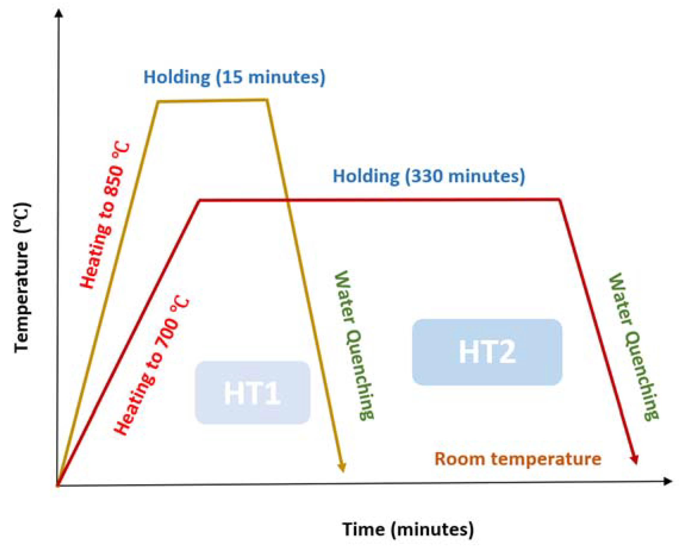
3/min) mass flow rate for 10 h. The vacuuming was performed to remove the water vapor and to prevent oxidation during the heat treatment. The UP150 controller was programmed to perform two different types of heat treatments, with a quick ramp up from room temperature to the set-point temperature and holding the temperature for a particular time. One heat treatment was for 15 min at a temperature of 850 °C followed by water-quenching, denoted by HT1. Another treatment was carried out for 5 h and 30 min at 700 °C followed by water quenching and is denoted by HT2. These heat-treatment parameters were chosen based on an ongoing study by our group that is focusing on achieving different microstructural and mechanical behavior because of heat treatment. Due to the rapid solidification nature of the LPBF process, there are residual stresses during the procedure that affect the final properties of the printed parts [
33]. Thus, there is a need for heat treatment to release the stresses within the fabricated samples. Based on previous experiences in the research group, these two sets of heat treatments (shorter and longer) were selected. For both the treatments the samples were quenched in water to cool them down to room temperature. The heat treatments have been illustrated below for a quick and easy understanding (
Figure 2).
The iMicro Nanoindenter from KLA Instruments (Milpitas, CA, USA) was utilized to evaluate the indentation creep behavior of both cast and printed samples in the heat-treated condition. For the indentation purpose, a Berkovich self-similar indenter was used. A customized standard ISO 14577 instrumented indentation method was employed to perform the creep tests. A maximum optimum load of 50 mN was applied on all samples with a loading rate of 2 mN/s. Next, the maximum load was held for a holding time of 600 s and then unloaded. Three indents were made on all samples with a 100 µm spacing between the indents. The data acquisition rate was customized at 100 Hz at the time of loading and unloading; 5 Hz was maintained during the holding time. The process parameters during the evaluation of indentation creep have been summarized in
Table 2.
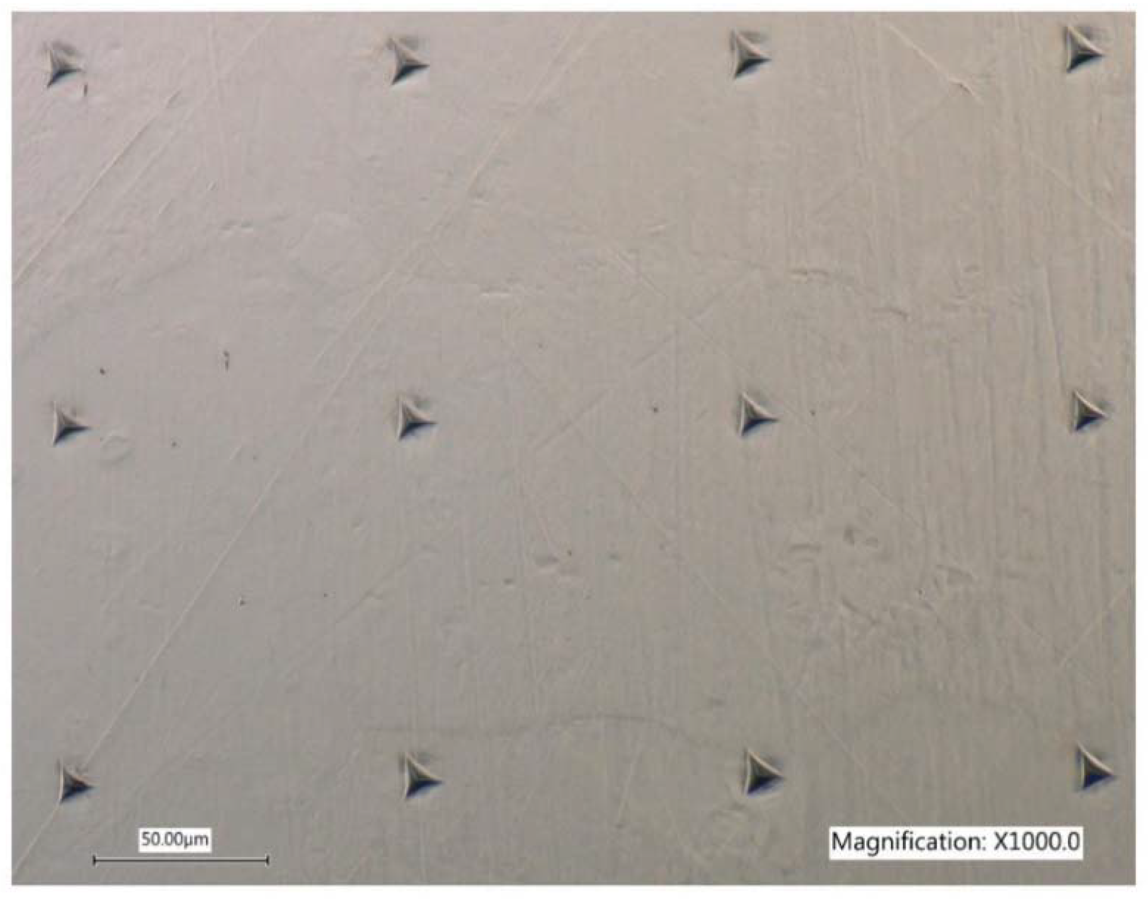
To perform simple indentation hardness tests for both cast and printed samples, the nano-indenter system equipped with the Berkovich indenter was utilized. A customized standard ISO method was employed with the same process parameters. The only difference was using the 3 s holding time in this case and keeping the data acquisition rate constant at 100 Hz all the time during the experiments. An array of 4 × 3 indents was made with a 100 µm spacing between the indents during the process. An illustration of the indentation tests with an array has been presented in
Figure 3. At a later stage before the indentation, the samples were mounted, ground, and polished with an auto-polisher to a mirror-like surface finish of 0.05 µm. Next, to reveal the microstructure, both the well-polished cast and printed samples were etched for 15 to 20 s. The etchant was made of HF, HNO
3, and distilled water with a ratio of 1:4:5, with volumes of 10 mL, 40 mL, and 50 mL, respectively. Microstructure and grain sizes of all materials, including cast and printed materials, were then examined through optical microscopy (OM).
4. Results and Discussions
Different process parameters in the AM technique could lead to different microstructural and thermomechanical behavior [
34,
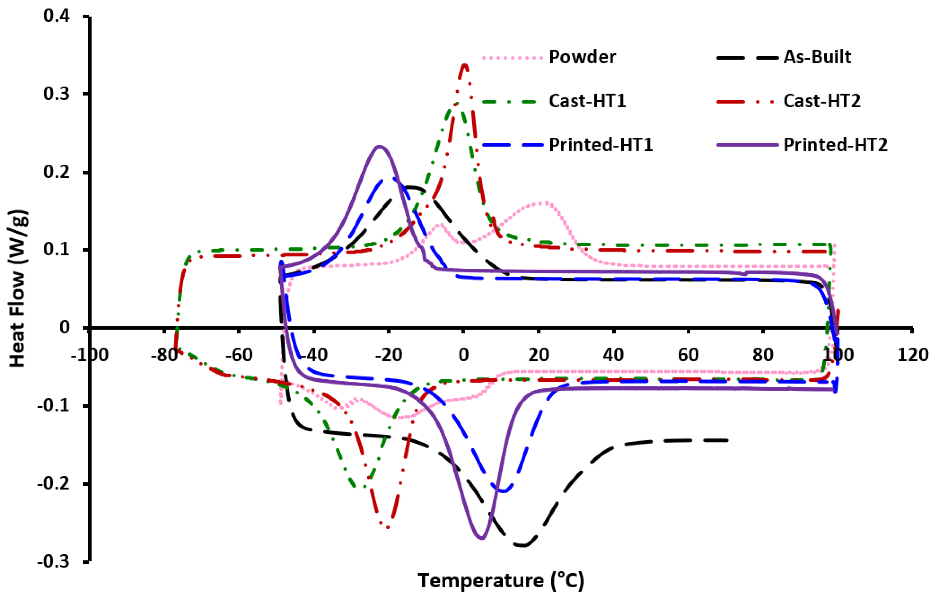
35]. Post-processing such as heat treatment can modify the thermomechanical behavior of the parts by changing the grain morphology and precipitations. Phase transformation temperatures were investigated for different fabrications and heat-treatment processes using differential scanning calorimetry (DSC). These phase transformation temperatures were then evaluated against the starting powder and the as-built sample. Corresponding DSC curves and characteristic temperatures (
Ms and
Af) for all samples are shown in
Figure 4 and
Table 3, respectively. It was found that the starting powder demonstrated a multi-stage phase transformation (both in forward and reverse transformation) that could be attributed to the presence of secondary phases which facilitate the formation of R phases [
36]. Thus, three peaks can be observed during the cooling segment, which are
B2→R,
R→B19′, and the remaining
R to B19′, respectively. At the same time, two peaks can be seen during the reverse transformation, resembling
B19′→R→B2 and
B19′→B2 in sequence [
37]. On the other hand, single-stage transformations were observed for the cast, powder-AM-fabricated and heat-treated samples.
The transformation temperatures (
Ms and
Af) were measured by the tangent line method. All samples except the as-built and powder showed an austenite finish temperature, indicating a fully austenitic structure at room temperature (pseudoelastic response). A variation in transformation temperatures (TTs) has been noticed between the cast and printed samples in the heat-treated condition. In general, printed samples showed higher TTs compared to the cast samples. This could be attributed to nickel evaporation during the powder preparation and the AM process. Between as-built and heat-treated printed samples, TTs dropped by about 15 °C and peaks were sharpened after the heat treatment. This can be explained by the dissolution of secondary phases that were formed during the SLM process after the heat treatment, yielding a more nickel-rich matrix [
38]. Saedi et al. [
38] investigated the influence of heat treatment on the thermomechanical response of Ni-rich NiTi alloys fabricated through SLM, and found that as-fabricated samples demonstrated higher TTs with broader peaks in comparison to cast ingot. It is acknowledged that the effect of matrix composition is crucial in defining the TTs of printed NiTi alloys. There are two prominent mechanisms in LPBF that give rise to subsequent compositional changes after fabrication: (1) Ni evaporation due to excessive heat; and (2) impurity pick-up. Ni has a lower evaporation temperature than titanium; hence, when associated with laser processing, Ni evaporates. This leads to a matrix composition with higher Ti content and the phase transformation temperatures increase [
39]. On the other hand, impurities deplete Ti from the matrix, resulting in a decrease in TTs. The balance between the two abovementioned mechanisms controls the increment/decrement of TTs for as-fabricated samples [
40]. Here, the nickel evaporation has a dominant effect and leads to the higher transformation temperature associated with printed samples and a lower transformation temperature of the cast samples. Although the initial nominal compositions for all the samples are the same, DSC results suggest that there is variation in the composition of the NiTi matrix. Hence, the compositional difference among the samples could give rise to variation in the creep performance.
4.1. Indentation-Derived Characteristics
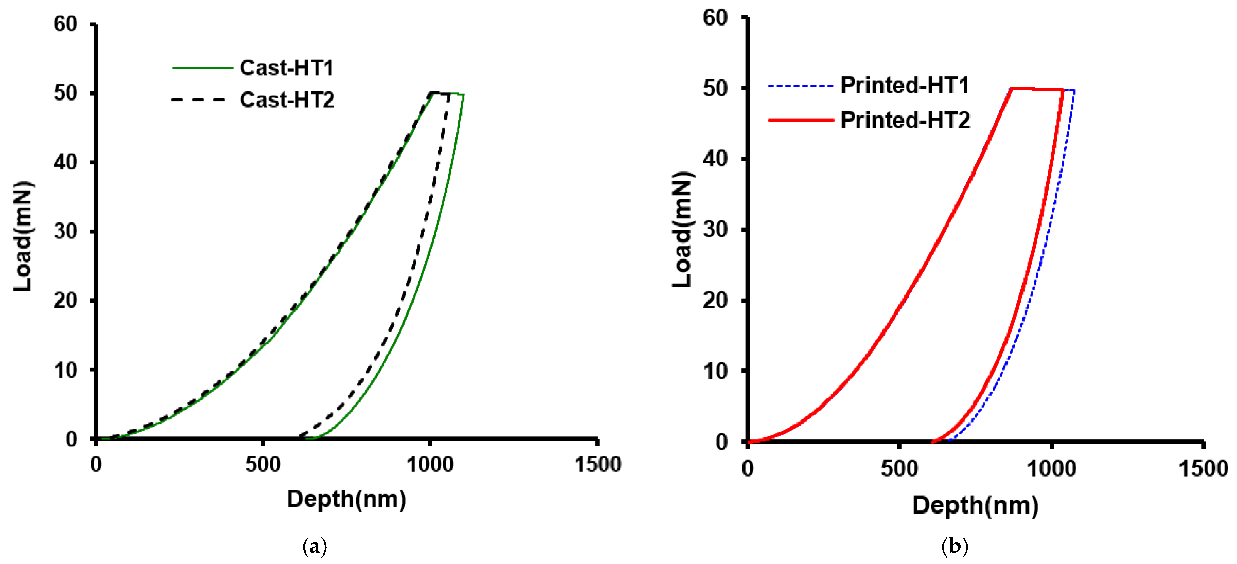
Figure 5 shows the representative creep
P-h (load versus displacement) curves for various NiTi samples at the peak load of 50 mN. Constant load-holding plateaus were noticed, in which the width differed from sample to sample based on the sample’s creep performance.
Figure 5a shows the typical creep
P-h curves for two heat-treated samples in cast conditions. Less displacement was required to achieve the same load for the cast-HT2 sample compared to the cast-HT1 sample. The characteristics of the load–depth curves conform to the hardness values, as found during the simple indentation tests, and have been presented in
Table 4. Shown in
Figure 5b are the
P-h curves of the printed materials, where printed-HT2, being harder, exhibits a smaller indentation depth as compared with the printed-HT1 sample. This is consistent with the hardness values found in simple indentation tests. It can be said that the samples exposed to longer heat treatments are harder than samples exposed to shorter heat-treatment periods.
4.2. Effect of Fabrication Method and Heat Treatment
To evaluate the effect of the fabrication method and heat treatment on the creep behavior of NiTi, it is very important to know the change in grain structures associated with each process. The microstructure of the fabricated parts depends upon the process parameters, in particular, the powder layer thickness, laser power, scanning speed, scanning path, etc., during the fabrication procedure through LPBF [
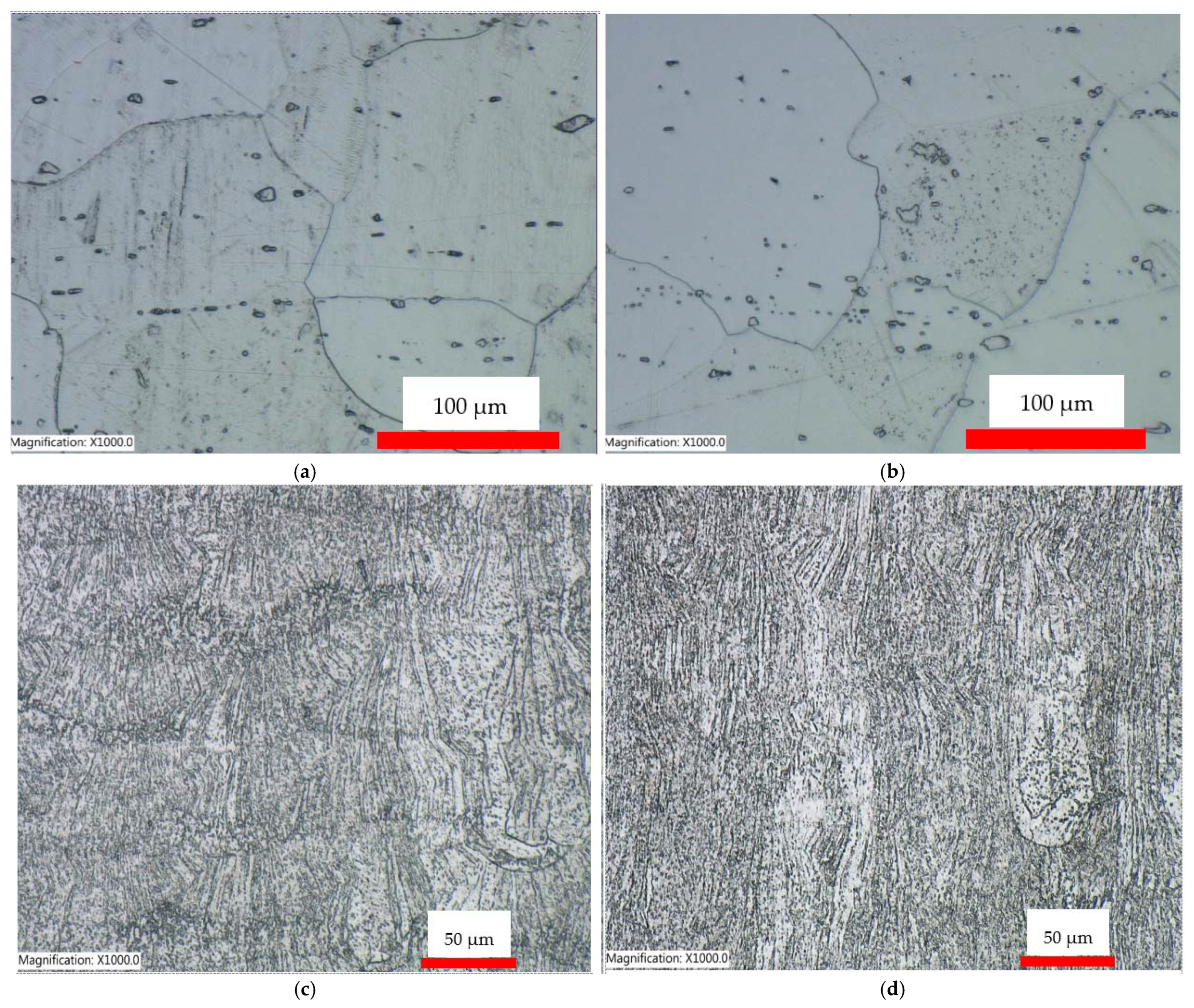
41]. The optical micrographs of cast-HT1, cast-HT2, printed-HT1, and printed-HT2 samples used in this study are presented in
Figure 6a–d. At room temperature, the heat-treated cast samples possessed a uniform microstructure with larger grain size (
Figure 6a,b). In contrast, non-uniform microstructure and columnar grains have been found in the printed samples in heat-treated conditions (
Figure 6c,d). These columnar grains in printed parts are comparatively smaller than the grains in cast samples because of the fast-cooling rate associated with the AM process.
Given the fact that materials with smaller grain sizes show better creep performance, printed samples should have better creep strength. However, additive manufacturing defects such as porosity, lack of fusion, etc., could manipulate this performance otherwise. Tadayyon et al. [
42] evaluated the deformation behavior of heat-treated Ni-rich NiTi alloys (51 NiTi) exposed to heat-treatment temperatures of 400, 500, 600 and 800 °C for 30 min followed by quenching in water. The resulting microstructure demonstrated a gradual coarser austenite structure (B2) phase, with the primary matrix containing a small number of precipitates. It was found that an increase in the heat-treatment temperature facilitated the grain growth and resulted in a coarser parent phase/austenite grain size with a wider size distribution. It is worth mentioning that at 800 °C, some of the newly formed grains grow over neighboring grains, giving rise to a greater range of size distribution. However, Eggeler et al. [
15] carried out an investigation on the microstructure of 50.7 at.% Ni alloy exposed to solution annealing at 850 °C for 15 min and subsequent water-quenching. The microstructure was found to consist of single-phase matrix material with oxide and carbide inclusions, but free of precipitates. This led to further investigation of the microstructure, i.e., whether samples containing precipitates, or no precipitates might create a difference in creep performance. Hence, the XRD analysis of cast and printed samples in heat-treated conditions has been carried out.
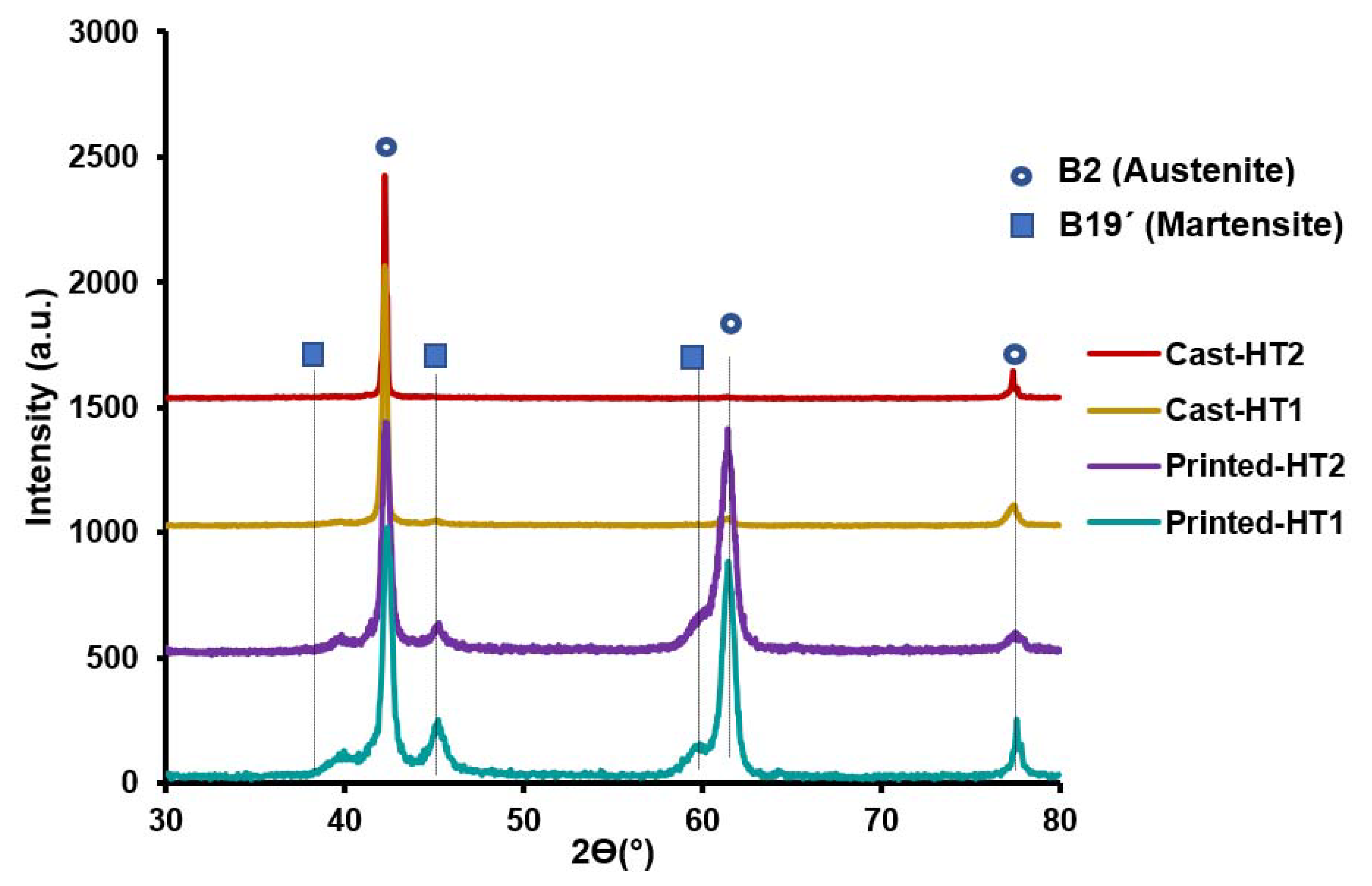
Figure 7 shows the XRD pattern of the cast and printed NiTi samples in the heat-treated condition. The XRD results are consistent with the DSC results reported earlier in this section. Based on the results, two groups of diffraction reflections can be observed in the spectra, where relatively stronger reflections are related to the austenite phase (B2) and the weaker reflections correspond to the martensite phase (B19′). Given that the integrated intensity of B2 austenite is higher everywhere compared to the B19′ martensite phase, it can be said that the B2 austenite is a dominant phase in the microstructure of all samples. The XRD spectra of all samples show that there was no significant change in the phases present in the microstructures of material, because B2 austenite and B19′ martensite has been observed in all samples. Although cast samples have mainly demonstrated the austenite phase, two distinguished reflections were observed for printed samples that corresponded to austenite and martensite phases. Hastuti et al. [
43] observed the formation of martensite in a NiTi alloy exposed to solution annealing and reported an associated discrepancy in Ni composition in the martensite which was formed directly from the solution-treated matrix. In short, heat-treated samples in printed condition demonstrated martensite reflections coupled with austenite reflections, whereas cast samples in heat-treated condition exhibited only austenite peaks. The reason could be that the A
f temperature, being close to room temperature, gives rise to the formation of martensite.
4.2.1. Indentation Creep Behavior
The stress distribution beneath the Berkovich tip is intricate (high triaxial stress in the magnitude of GPa) compared to conventional creep tests, which results in a creep deformation of materials even at room temperature. The high shear stress value under the indenter [
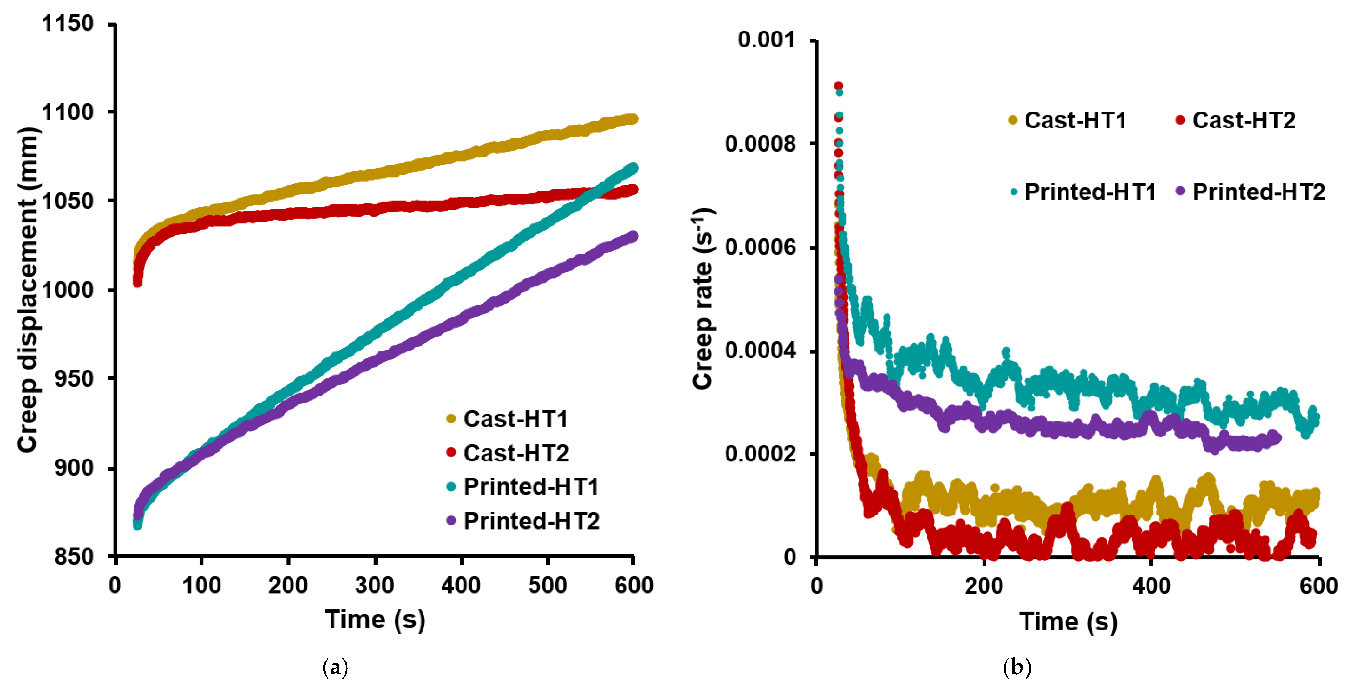
30] at a very small displacement facilitates overcoming the yield stress in a particular material and causes creep. The correlation between creep displacement and constant load-holding time under a maximum load of 50 mN for cast and printed NiTi samples with heat-treated conditions has been illustrated in
Figure 8a. Initially, every single curve experiences a sharp rise at the primary/transient creep stage. Afterwards, as the indenter penetrates the specimen, there is a linear rise in creep which brings on a steady-state creep, analogous to the uniaxial tensile/compression creep. For all cast samples in
Figure 8a, creep-induced displacement at the end of dwell time was higher for the cast-HT1 specimen (∼1100 nm), followed by the cast-HT2 specimen (∼1060 nm). In addition, for heat-treated samples in printed conditions, shown in the same figure, creep displacement for printed-HT1 and printed-HT2 samples reached ∼1070 nm and ∼1030 nm, respectively, at the end of the holding stage. One definite pattern has been observed for creep displacement of the heat-treated samples. Samples with a prolonged heat treatment (HT2) always exhibited a smaller creep displacement in contrast to samples exposed to a shorter heat-treatment period (HT1).
Indentation creep rates acquired using Equation (2) have been plotted versus holding time, as illustrated in
Figure 8b. At the outset, a sharp decline in creep (transient creep) has been observed according to an increase in the dwell time, and ultimately, a plateau trend or steady-state creep has been achieved. Even in the steady-state creep process, some features of work hardening can be seen as the creep rate decreases with time until eventual exhaustion. It has been observed from the figure that the time required to reach steady-state creep condition for all samples was the same, around 100 s. The cast-HT1 sample showed an initial sharp decrease in creep rate up to ∼0.0001 s
−1 followed by a nearly steady creep rate at holding time before steady-state creep, whereas the cast-HT2 sample demonstrated a lower creep rate of ∼0.00005 s
−1. In contrast, an earlier reduction in creep rate for the printed-HT1 sample has been found as ∼0.0003 s
−1 before the steady-state condition, whereas an initial sharp decrease in creep rate of up to ∼0.0002 s
−1 has been observed for the printed-HT2 sample. The reason for the distinct creep behavior of samples exposed to different heat-treatment periods could be attributed to heat-treatment time. A higher heat-treatment period results in coarser precipitates, thus yielding a harder sample compared to the samples exposed to shorter heat-treatment time. On another note, it was found that printed samples experienced more creep displacement and creep rate, in contrast to the cast samples. Additive manufacturing defects such as porosity, lack of fusion, etc., could be the main cause of this performance.
The reason for the distinct creep behavior of samples exposed to different heat-treatment periods could be attributed to the heat-treatment time. We found that printed samples experienced more creep displacement (less creep resistance). Structural defects associated with the additive manufacturing of NiTi and microstructural inhomogeneities inherited with the powder laser bed fusion process (pores/porosity and crack formation due to the presence of residual stress) could be the main cause of weaker creep performance of the printed parts. Annealing heat treatment between 800 and 1050 °C, however, eliminated the residual stress and established microstructural homogeneity. Additionally, aging at a particular range of temperatures from 300 to 700 °C helped in regaining the initial strength through the formation of Ni-rich precipitates. The hardening achieved through precipitation serves as a barrier for dislocation motion, thus improving the hardness and creep properties. Our findings are in agreement with Bridges et al. [
44], who investigated the creep performance of a cast and additively manufactured Ni-based superalloy. They observed an enhanced time-dependent property in the conventional casting material over the AM-processed material. Bridges et al. observed fewer intermetallic compounds (i.e., MC and M23C6 carbides) near grain boundaries which were responsible for reduced creep properties connected with the AM process. Furthermore, Banoth et al. [
45] investigated the creep performance of IN 939 in the cast and AM conditions with low- and high-temperature heat treatment. They reported that the creep life of the cast sample was better than the SLM sample, and attributed this trend to a low creep strain rate and bigger grain size associated with the cast material.
4.2.2. Indentation Size Effect (ISE) and Creep Stress Exponent (n)
The variation of indentation hardness/indentation stress concerning indentation depth/impression size during the indentation test is called the indentation size effect (ISE) [
46]. Generally, the ISE is ascribed to geometrically necessary dislocations (GNDs) within the plastic region, which are beneath the indents subjected to a strain through the mechanism-based gradient plasticity theory [
47]. When an indenter penetrates a material, GNDs are initiated to support the required lattice rotation in adapting the indenter shape with an additional dislocation density as opposed to being strained uniformly [
48]. GNDs could be aligned along non-easy slip crystal systems originating within a tiny zone beneath the indenter, engendering dissimilar burger vectors and mobility, serving as obstacles to ordinary dislocations. Thus, a joint effect from the abundance of GNDs along with a higher indentation loading rate gives rise to a substantial strain gradient or work hardening effect below the indenter. In addition, strain gradient could be influenced by a combined effort of indentation depth, temperature, and deformation rate [
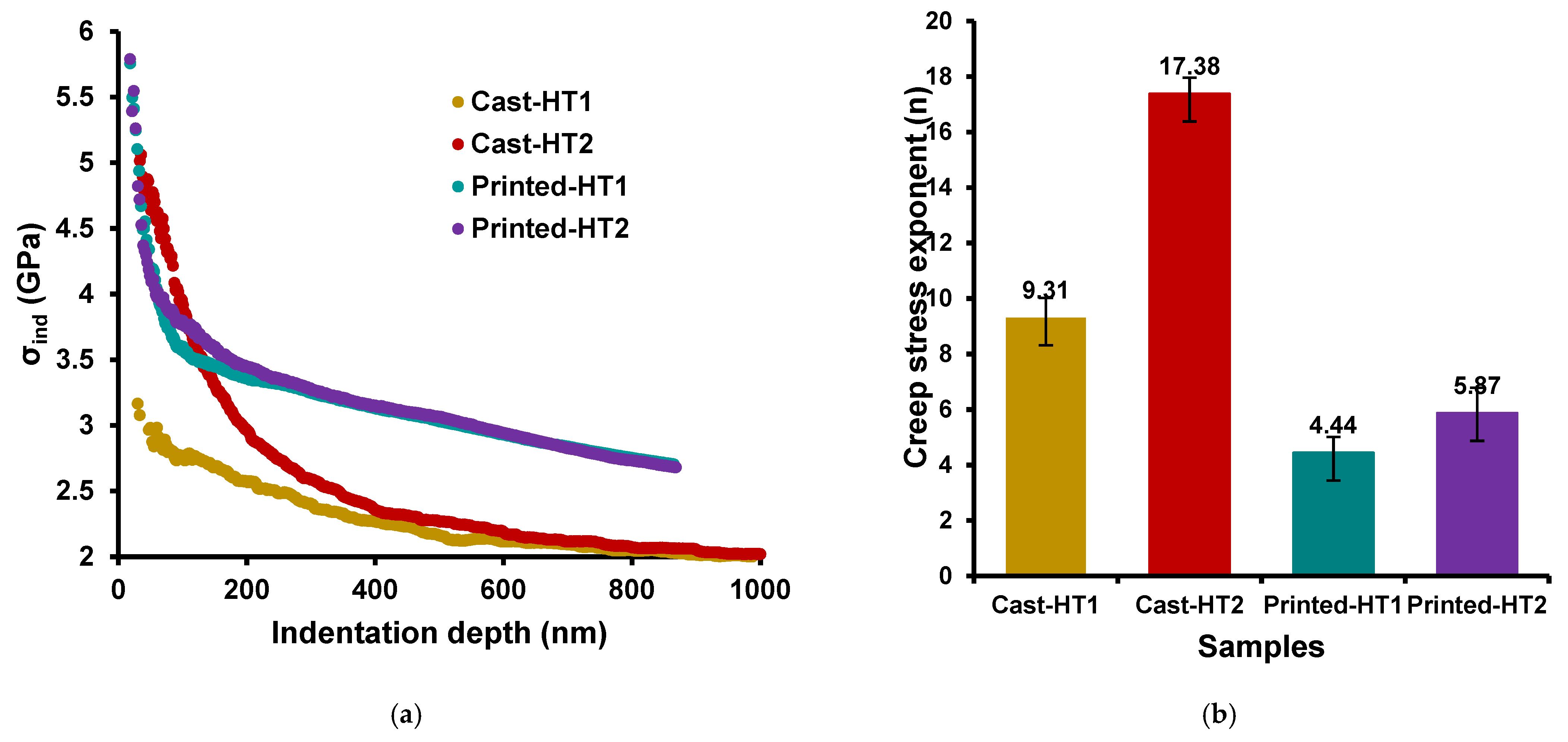
49]. Nevertheless, a decline in GNDs density and contribution is inevitable relative to a rise in indentation depth. Indentation stress vs. indentation depth curves are plotted in
Figure 9a. Substantial indentation size effects have been noticed for both cast and printed NiTi samples in heat-treated conditions. For a maximum load of 50 mN, observed indentation depths are the same for two heat-treated samples in cast conditions as well as in printed conditions. It has been observed that the heat-treated printed samples experienced a lower indentation depth compared to heat-treated samples in cast conditions.
The creep stress exponent (
n) is usually used to reveal the real creep properties along with deformation mechanisms taking place during the indentation test and relies upon the maximum indentation load. The stress exponent can be expressed as a combined function of microstructure, mobile dislocation density, and/or the activation area underneath the indenter [
50]. The range of
n-values is a standard in interpreting the dominant creep mechanism at ambient as well as at elevated temperatures. The stress exponents have been calculated from the slope of
against
curves using Equation (6) for different cast and printed samples in heat-treated conditions (
Figure 9b). Considering the
n values for this study, from the figure, all the values are greater than three for all samples and the creep mechanism is governed by dislocation movement (i.e., glide/climb) [
16]. In other words, the secondary stage of the creep behavior in the cast and printed NiTi samples in the heat-treated condition is dominated by the dislocation movement.
From
Figure 9b, it can be observed that the creep stress exponent value increases from 9.31 to 17.38 when the cast NiTi sample is exposed to a longer heat-treatment period, denoted by HT2, compared to the shorter heat-treatment period of HT1. In addition, an increase in the value of n from 4.44 to 5.87 has been noticed for heat-treated samples in printed conditions. These samples were exposed to HT1 and HT2 heat-treated conditions, respectively. There is a clear trend of a higher stress exponent value exposed to a longer heat-treatment (HT2) than shorter heat-treatment method (HT1). Furthermore, it can be deduced from
Figure 8b and
Figure 9b that the creep process exhibited the lower stress exponent when a sample had a higher steady creep rate. Conversely, the creep process exhibited higher stress exponents when it experienced a lower steady creep rate. Zhu et al. [
51] investigated the room temperature nanoindentation creep of nanoscale Ag/Fe multilayers and found the same trend between creep rates and stress exponent values.
