Article

Functional Analysis of Components Manufactured by a Sheet-Bulk Metal Forming Process

1
Institute of Manufacturing Technology, Friedrich-Alexander-Universität Erlangen-Nürnberg, 91058 Erlangen, Germany
2
Institut für Werkstoffkunde (Materials Science), Leibniz Universität Hannover, 30823 Garbsen, Germany
3
Engineering Design, Friedrich-Alexander-Universität Erlangen-Nürnberg, 91058 Erlangen, Germany
*
Author to whom correspondence should be addressed.
J. Manuf. Mater. Process. 2021, 5(2), 49; https://doi.org/10.3390/jmmp5020049
Submission received: 20 April 2021 / Revised: 6 May 2021 / Accepted: 11 May 2021 / Published: 17 May 2021

Abstract

:
Due to rising demands regarding the functionality and load-bearing capacity of functional components such as synchronizer rings in gear systems, conventional forming operations are reaching their limits with respect to formability and efficiency. One way to meet these challenges is the application of the innovative process class of sheet-bulk metal forming (SBMF). By applying bulk forming operations to sheet metal, the advantages of both process classes can be combined, thus realizing an optimized part weight and an adapted load-bearing capacity. Different approaches to manufacturing relevant part geometries were presented and evaluated regarding the process properties and applicability. In this contribution, a self-learning engineering workbench was used to provide geometry-based data regarding a novel component geometry with circumferential involute gearing manufactured in an SBMF process combination of deep drawing and upsetting. Within the comprehensive investigations, the mechanical and geometrical properties of the part were analyzed. Moreover, the manufactured components were compared regarding the increased fatigue strength in cyclic load tests. With the gained experimental and numerical data, the workbench was used for the first time to generate the desired component as a CAD model, as well as to derive design guidelines referring to the investigated properties and fatigue behavior.

1. Introduction

Due to increasing economic and ecologic restrictions and a rising demand for global sustainability, new products and technology approaches are necessary to meet the upcoming challenges [1]. Especially in the manufacturing industry, the development of innovative solutions is essential to meet requirements and emerging challenges. New approaches such as light-weight design and functional integration are applied to reduce weight on the one hand, and to increase the functionality on the other hand [2]. Consequently, conventional manufacturing processes are reaching their limits due to an increased complexity of the components and a lack in production efficiency. The innovative process class of sheet-bulk metal forming (SBMF) offers the possibility to meet these challenges by an efficient manufacturing of functional components with a shortened process chain and improved mechanical properties [3]. By applying bulk forming operations to sheet metal, the three-dimensional stress and strain states can be used to locally adjust the thickness or properties of the component. Within the Transregional Collaborative Research Centre 73 (TCRC 73), this process class is investigated fundamentally, applying different process approaches to manufacture components with varying geometric dimensions and functional elements. An overview of the possible geometries, as well as the corresponding manufacturing processes, are given in [4]. Furthermore, a comparison of the required forming force and the possible material volume by the different operations was presented. During the investigation, the conflict between the desired geometry and the process limits could be shown and the necessity of pre-calculated values referring to the mechanical properties and the performance in operation for an optimized component design could be demonstrated. Since the functional components are exposed to cyclic load during usage [5], the analysis and evaluation of the fatigue life is mandatory for characterizing the potential of an increased performance. In order to allow a future substitution of conventionally manufactured components with SBMF parts, the comparison between the initial material state and the work-hardened state as a consequence of cold forming appears reasonable.
Within this contribution, functional components with circumferential involute gearing manufactured by an SBMF process are investigated regarding their geometrical and mechanical properties. To generate a fundamental data basis and to ensure the manufacturability of the components, a geometry-based and a data-based approach are combined within the self-learning engineering workbench SLASSY. To support the design of complex components in the context of SBMF, a geometry-based approach, referring to the overview of different manufacturing processes in [4], should be implemented into the self-learning engineering workbench [6]. By fundamentally investigating and evaluating a process combination of deep drawing and upsetting to manufacture functional components with circumferential involute gearing, the mechanical and geometrical properties, as well as the fatigue life of the component, should be analyzed. Besides the use of a conventional blank of the mild deep drawing steel DC04 (1.0338 DIN EN 10130), the potential of process-adapted semi-finished products applied within the process combination should be evaluated. The applied methodology is exemplarily shown in Figure 1. In order to predict different characteristics on the basis of design parameters for possible geometries and to expand the applicability of the engineering workbench SLASSY within the context of SBMF, this contribution is concluded by a data-based analysis of the geometrical and mechanical properties.

2. Geometry-Based Approach within SLASSY

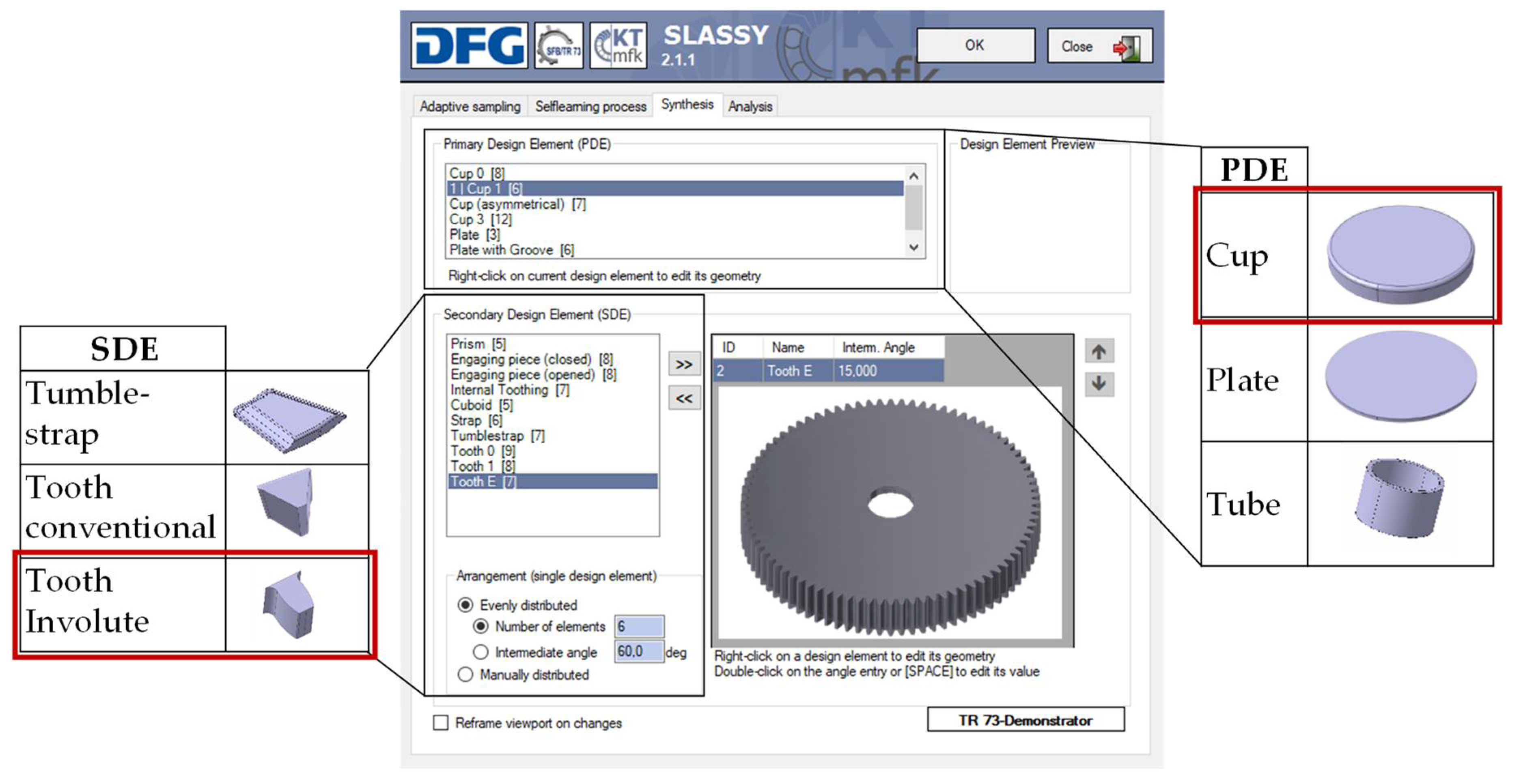
Since the process class of SBMF is characterized by a three-dimensional stress and strain state as well as material flow and a complex tool and process setup, the design of such components requires a comprehensive process and component understanding. In this context, the self-learning engineering workbench SLASSY was created. With its application in sheet-bulk metal forming, the synthesis between geometrical parameters and mechanical properties should be enabled [6]. The step of creating design rules with the help of different experimental investigations is thereby replaced by the possibilities of the workbench. SLASSY automatically extracts and presents relevant knowledge during the design process inside the CAD system used. For this purpose, techniques from direct and indirect knowledge acquisition are used. Moreover, machine learning methods are applied to extract implicit knowledge from simulation or experimental data by means of metamodels [7]. These models are a description of the correlation between the input product features, such as the geometry, and output product properties, such as the manufacturing parameters [6]. In the first step, developers design the SBMF part inside their CAD system with the support of the SLASSY workbench. This is the so-called synthesis step, which combines geometrical properties with the related manufacturing process. Sheet-bulk metal formed components can be configured by choosing a basic body element from a given set of primary design elements (PDE) such as flat or curved sheets or cups. Secondary design elements (SDE) such as carriers or gearings can be added to complete the functional component [6]. All presented functional components in [4] are implemented in the database and can be combined to create new parts independently. An overview of the desktop surface with exemplarily depicted elements and the described synthesis step is shown in Figure 2. The combination of the cup as a primary design element and the involute gearing as a secondary design element results in the depicted component on the bottom right side. The generated component is generated in the CAD system used according to the chosen elements and can then be further processed.
The second step of applying the workbench is the analysis step of the geometry parameters and mechanical properties considering the selected experimental results. In the following, the experimental investigation of the parts manufactured with the process combination of deep drawing and upsetting is presented. The main aspects in this context are the geometrical and mechanical properties, as well as the determination of the fatigue life of the sheet-bulk metal formed parts, as compared to conventionally manufactured components.

3. Mechanical Analysis

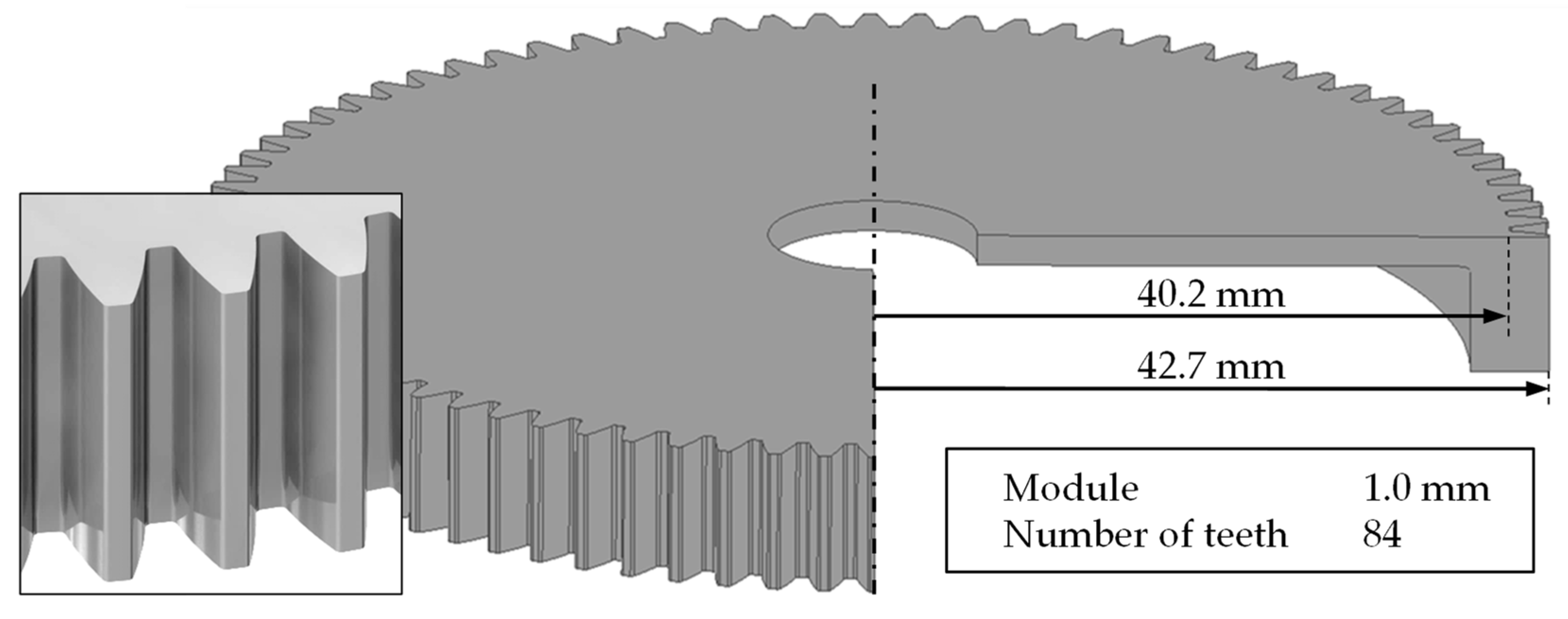
In contrast to the state of the art as described in [8], a combined deep drawing and upsetting process to manufacture functional components with a circumferential involute gearing was investigated in the present contribution, cf. Figure 3. The involute gearing featured a module of 1.0 mm with a tooth width of 2.5 mm, defined by the tip radius of 42.7 mm and the root radius of 40.2 mm. The total number of teeth was 84, which were evenly distributed around the circumference.
In this chapter, the experimental setup is explained for generating a basic process and component understanding. Furthermore, the forming results, as well as the possibilities for enlarging the forming limits within the described process, are presented.

3.1. Forming Process

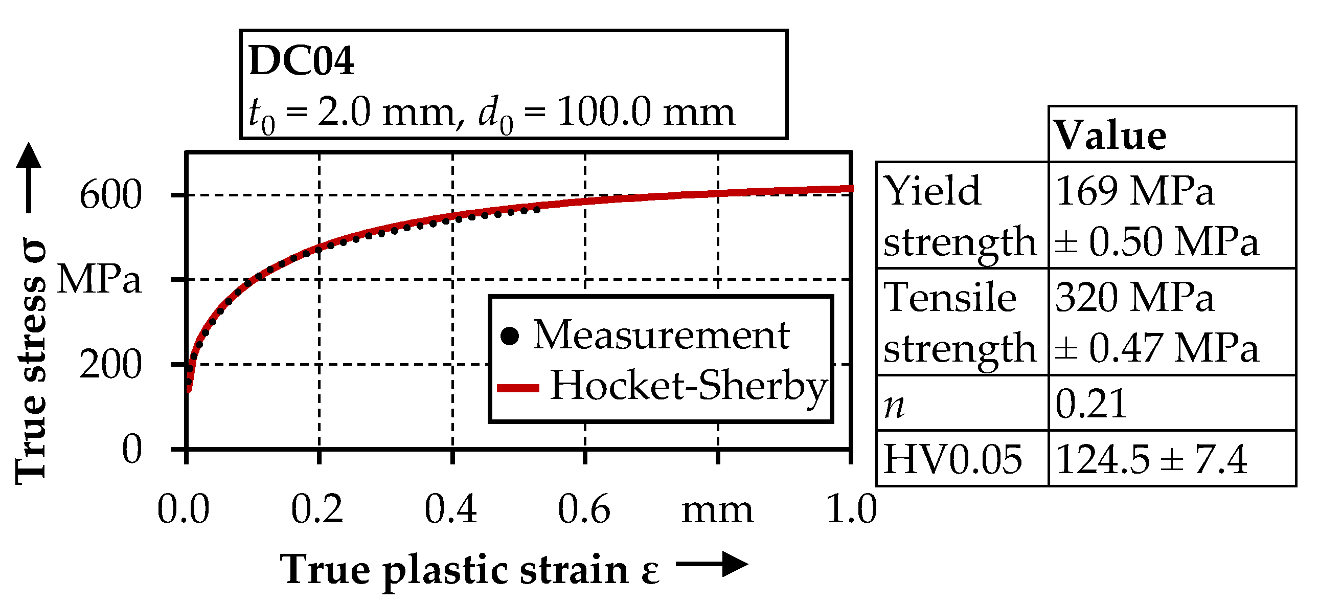
For the investigation, a mild deep drawing steel DC04 (1.0338) was used with an initial sheet thickness of t0 = 2.0 mm and an initial diameter of d0 = 100.0 mm. This steel is characterized by a high formability at medium strength and is used in automobile applications such as different chassis parts or narrow profiles. The mechanical properties of the material are presented in Figure 4. Besides the material parameters such as the yield strength, the flow curve is shown, which was generated by layer-compression tests and extrapolated with the Hocket–Sherby approach to enable a realistic material behavior in the context of SBMF processes with three-dimensional compressive stresses.
Within the TCRC 73, the process combination of deep drawing and upsetting to manufacture functional components with a demonstrator gearing was fundamentally investigated [8]. This investigation focused on the component with an involute gearing, thus differing in the process and tool setup, as presented in the following paragraph.
The setup of the combined, single-stage deep drawing and upsetting process is depicted in Figure 5. The tool consisted of a drawing punch, a drawing die, an upsetting punch, and an upsetting plate. The sheet was placed onto the drawing punch and clamped by the upsetting punch with a clamping force of FC = 400 kN. The deep drawing process began with an axial movement of the drawing die, which was controlled by the drawing force FD to form the cup wall. After reaching the upsetting plate, the upsetting process was initiated within the same stroke by the displacement of the drawing die as a consequence of an applied upsetting force FUp into the upsetting punch. Subsequently, the cup wall was reduced in height and a lateral material flow into the cavity located on the inner side of the drawing die was realized. The final height of the component depended on the defined forming force.

3.2. Forming Results

In the first step, a conventional blank with an initial sheet thickness of t0 = 2 mm was applied as a semi-finished product for the reference geometry. As presented in the previous chapter, the deep drawing operation was used to realize the basic cup shape of the component. After deep drawing, the cup height amounted to h = 14.78 mm. Due to the occurring stress and strain states, a material thinning at the drawing punch radius occured, analogous to [8]. The minimum sheet thickness amounted to tmin = 1.76 mm, whereas the maximum sheet thickness amounted to tmax = 2.02 mm due to tangential compression stresses in the lower area of the cup wall. Subsequently, the drawn cup was upset with a maximum upsetting force of FUp = 800 kN. The resulting part contour is presented in Figure 6. The cup height after upsetting amounted to h = 8.41 mm. Since the material volume provided by the conventional blank remained constant at Vconv = 6754 mm3, the form filling of the tooth area including the cup wall was only dependent on the desired cup height. Referring to a required material volume of Vreq = h × 932.7 mm3/mm, derived from the CAD-Model, the form filling with a height of h = 8.41 mm reached up to 86%. The contour of the experimentally manufactured part, however, showed large deviations to the target geometry. The buckling of the cup wall was identified as a major process failure for insufficient material volume in previous investigations [9], and required the application of process-adapted semi-finished products [8]. The other characteristic failure for the application of conventional semi-finished products was the folding of the material at the drawing punch radius, as shown in the depicted microstructure in Figure 5. The results of the micro hardness distribution demonstrated the increase of the hardness due to cold hardening in areas of high deformation, thus revealing an increase of 87% up to 233.4 ± 30.1 HV0.05.
Regarding the results referring to the use of a conventional blank, the process limits were clearly visible. To enable a near net-shape contour of the final part, the form filling, and thus the maximum material thickening, in the cup wall had to be increased by the application of process strategies in order to control the material flow.

3.3. Process Strategies to Enlarge the Form Filling

In order to avoid process failures during the manufacturing of the functional components, a defined control of the material flow was mandatory. Apart from the application of tailored surfaces on the tool side [10] or thermal grading [11], the use of rotational symmetric tailored blanks, products with process-adapted geometrical and mechanical properties, offers great potential [8]. Additionally, due to the adapted thickness profile of the semi-finished products, the die filling during the subsequent forming process can be increased. For the manufacturing of such tailored blanks with various thickness profiles, the two different sheet-bulk-metal forming processes of orbital forming and a circular flexible rolling process were investigated within the TCRC 73. In order to achieve the high process forces, which are typical for sheet-bulk-metal forming, both processes have incremental properties. Thereby, the orbital forming process is similar to a conventional upsetting process, with the difference being that one tool component is adjusted by a defined tumbling angle. In Figure 7a, the process setup is schematically shown for the initial position, as well as for the tumbling position. This tool concept was used in a TZP400/3 hydraulic deep-drawing press from Lasco with an additional tumbling plate. At the process beginning, the forming force F was applied by the upper punch, which had a defined punch angle, whereby the perpendicular axis was fixed in its position. Subsequently, the counterpunch, with die cavities as a counterpart of the tailored blank, moved with a defined tumbling motion and angle. The course of the tumbling angle depending on the number of tumbling cycles is shown in Figure 7b. It can be divided into three phases, the upcoming phase, where the tumbling angle is increased to the target value. Depending on the process setup, a maximum tumbling angle of 1° could be achieved. During the constant phase, the tumbling angle was held constant on the target value with a subsequent decrease to the initial position in the third phase. By using this process setup, tailored blanks with homogenous rotational and cyclic-symmetric thickness profiles [8], as well as discrete functional elements such as involute gearings perpendicular to the sheet plane or both-sided thickenings [12], could be manufactured. Thus, it offers potential for increasing the component quality, as well as for shortening the process chain.
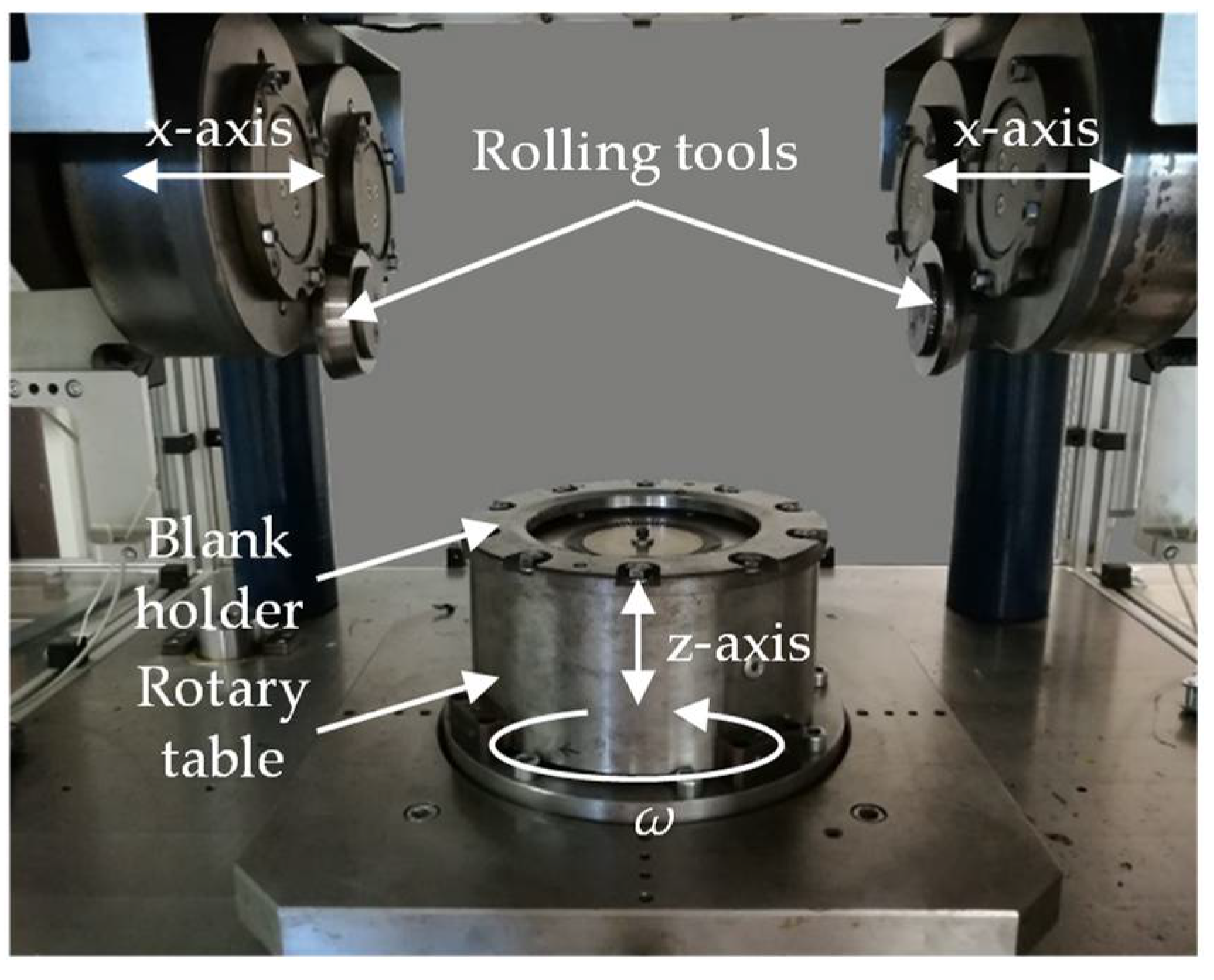
In addition to the orbital forming process, a new circular flexible rolling process was investigated within the TCRC 73. The fundamental principle of the rolling process is shown in Figure 8 and described in detail in [8]. At the process beginning, the initial blank was clamped onto the rotary table by a hydraulic blank holder. Just as in the orbital forming process, the rotary table had die cavities with the geometry of the counterpart of the target tailored blank geometry. Thereby, the rotary table could move infinitely along the z-axis and had an active rotatory drive. On the other side, the two rolling tools were only pivoted on the x-axis and could move in a linear direction. Due to a defined vertical roll displacement ∆t related to the surface of the blank superimposed with the rotational movement of the rotary table and the horizontal movement of the rolling tools, a defined material flow in the radial, axial, and tangential directions could be achieved. By mounting different rotary tables with varying geometries, the same tailored blanks as by using the orbital forming process could be manufactured. Compared to the orbital forming process, the advantage of the flexible rolling machine was the significant reduction of the contact area. Thus, the required forming force was reduced, with the advantage of extending the process limits for the formability of even higher strength materials.
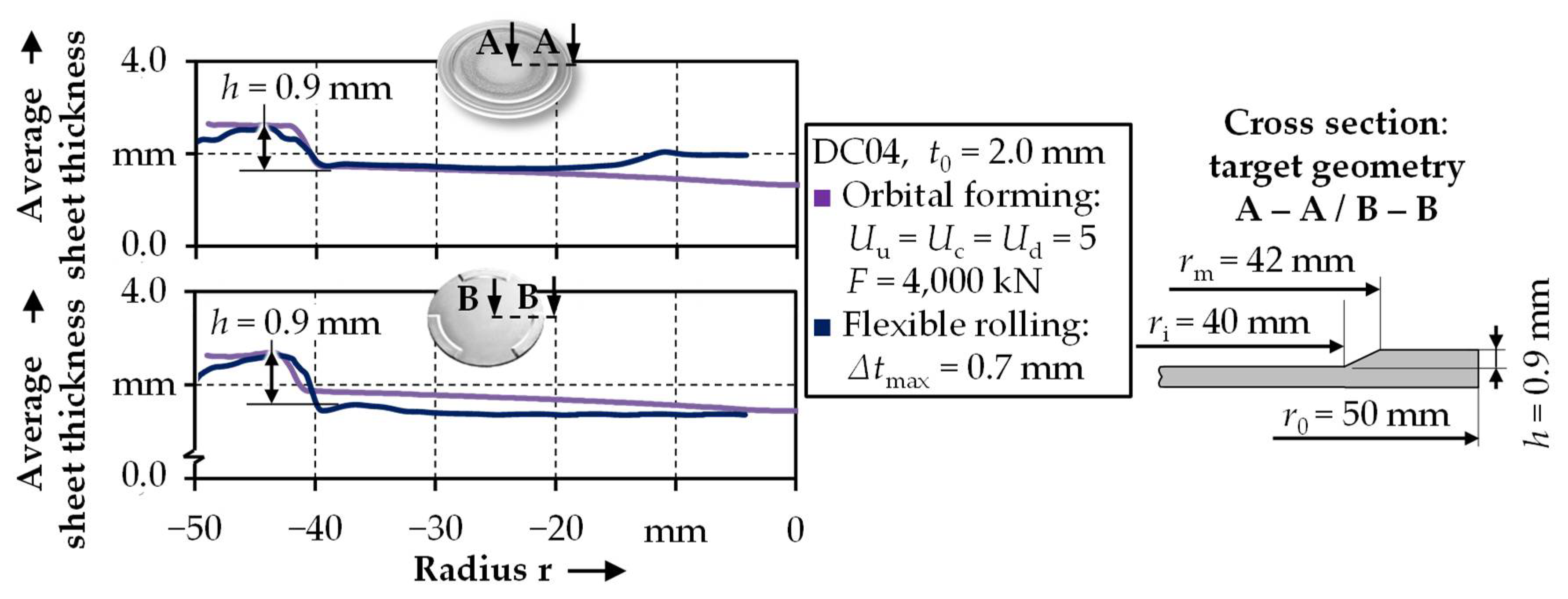
Depending on the process control strategy, similar thickening heights could be achieved with orbital forming [8], as well as with the flexible rolling processes [13]. In Figure 9, the average sheet thickness is shown for a rotational and a cyclic-symmetric tailored blank geometry. The respective target geometry is shown on the right side. While an average sheet thickness of tavg = 2.51 ± 0.51 mm was achieved by the tumbling of a rotational symmetric tailored blank, a thickening of tavg = 2.46 ± 0.47 mm could be achieved by the flexible rolling process. Especially when manufacturing a cyclic-symmetric tailored blank geometry, it can be seen that a more homogenous sheet thickness can be achieved in the thinned area for the flexible rolling process, since the center thinning effect is caused by the material flow during the orbital forming process.
The application of tool sided tailored surfaces can also be used for the targeted control of the material flow for the manufacturing of tailored blanks. Investigations in [14] have shown that an increase in the die filling can be achieved by applying high-feed milled surfaces. Depending on the orientation of the modified surface, the material flow can be improved or inhibited.
Comparing the overall results, the tailored blanks manufactured by orbital forming showed the highest average material thickness in the desired area. Therefore, the tailored blank was further processed in the combined deep drawing and upsetting process, aiming at improved part properties. After the deep drawing operation, the cup height amounted to h = 13.41 mm. Thus, the cup drawn from the tailored blank was more than 1.3 mm lower than the cup drawn from the conventional semi-finished product due to the cold hardening of the material and the reduced thinning at the drawing punch radius. In the subsequent upsetting operation, the cup height was reduced by applying a maximum upsetting force of Fmax = 800 kN to the drawn cup. According to the process description in Section 3.1, the material in the cup wall was forced to flow into the gear cavity. The additional material allocated within the manufacturing of the tailored blank enabled an improvement of the die filling and the reduction of the deviation to the target geometry, as presented in Figure 10.
By applying the orbital formed tailored blank in the investigated process chain, the provided volume in the outer segment reached VTB = 8152.5 mm3. Referring to the formula to calculate the required material volume Vreq = h × 932.7 mm3/mm and an actual cup height of h = 8.98 mm, the form filling could be increased to 98%.
The functional component showed only minor areas of insufficient die filling. This underlines the potential of the application of tailored blanks in SBMF processes. The microstructure depicted in Figure 10 confirms this potential, as both process failures were reduced by applying a tailored blank. Furthermore, the homogeneity of the hardness increased due to an improved material flow control. The average hardness value of 220.3 ± 22.9 HV0.05 represented a decrease of 6% compared to the hardness of the conventionally manufactured component.
Within this paragraph, the properties of the components, as well as the possibility of optimizing the target values, were presented. This geometrical and mechanical properties can be used as basic metadata for the engineering workbench. To comprehensively evaluate the industrial applicability of the components, investigations on the fatigue behavior were carried out.

4. Fatigue Life Testing and Modeling

In order to predict the fatigue life of the sheet-bulk metal formed components, a fatigue model was elaborated and parameterized. Subsequently, cyclic fatigue experiments were carried out on the components’ external toothing for validation. The fatigue model could then be used to calculate a fatigue life prediction for the work-hardened material state and also for the initial state of the DC04 mild steel. This is assumed to be a good indicator for comparing the benefits of the forming technology in contrast to manufacturing by machining. By implementing the fatigue model into the SLASSY workbench, the influence of alternative geometries to the components’ fatigue strength could be determined.

4.1. Fatigue Life Modeling

A fracture mechanical approach was used for predicting the fatigue life of the sheet-bulk metal formed components. To consider the elastic–plastic material behavior, the cyclic ∆J-integral approach [15], also referred to as the Z-integral approach [16], was employed. Thereby, the crack propagation per cycle da/dN was calculated depending on the elastic Wel,eff and plastic Wpl energy densities converted during one cycle (Equations (1) and (2)). This approach was established for unalloyed and low-alloy steels [17].
d a d N = C J · ( Z ) m J
Z = a · ( 2.9 · W el ,   eff + 2.5 · W pl )
The parameters CJ and mJ are material-dependent and can be determined from long crack growth experiments. By analyzing the stress–strain hysteresis in strain-controlled fatigue experiments, the elastic and plastic energy densities Wel,eff and Wpl can be determined. Wpl is provided by the area below the ascending hysteresis-branch [18]. The effective elastic energy density Wel, eff can be obtained from the effective stress amplitude Δσeff, for which the fatigue crack is opened and capable of growth, and from the Young’s modulus E as
W el ,   eff = Δ σ eff 2 2 E
The number of cycles to failure Nf can then be calculated by integrating the crack propagation from an initial crack length a0 to a given crack length af, which is used as the failure criterion:
N f = a f ( 1 m J ) a 0 ( 1 m J ) C J · ( 1 m J ) · ( 2.9 · W el ,   eff + 2.5 · W pl ) m J

4.2. Data Acquisition on Different Material States

Since the secondary form elements were too filigree to extract fatigue specimens and also possessed strongly graded properties (cf. hardness mapping in Figure 10), a material state had to be produced that featured mechanical properties similar to the components, as presented in more detail in [5]. For this purpose, sheet metal strips from DC04 were rolled from their initial sheet thickness of 3 mm to 1 mm using a two-roll rolling mill. In hardness measurements, this material state showed an average hardness of 193 HV10 (determined at 5 measuring points, standard deviation <3%) and agreed well with the hardness in the tooth root area of the component (cf. Figure 10).
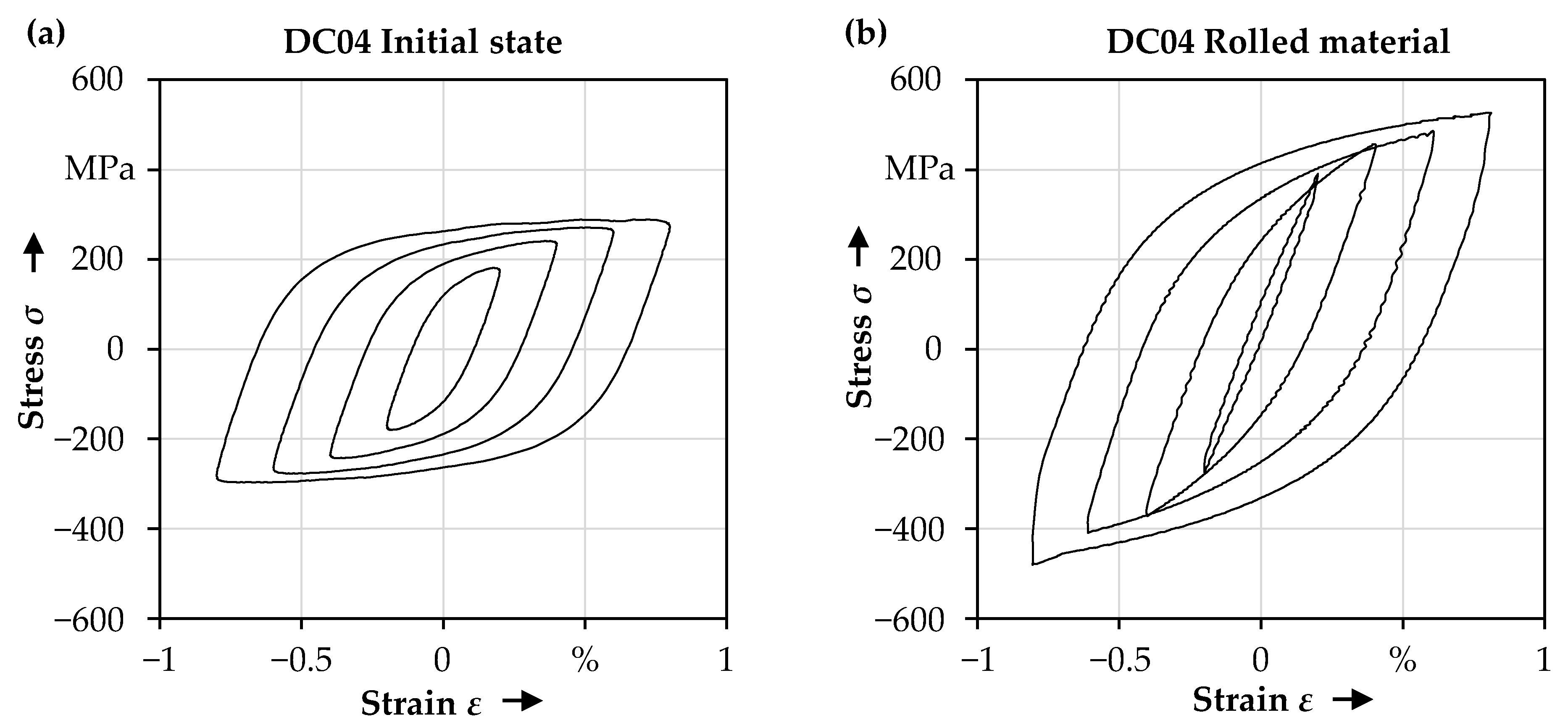
From these sheet metal strips, the specimens for strain-controlled fatigue experiments were extracted in the rolling direction, as schematically depicted in Figure 11a. Stress–strain hysteresis on those specimens were recorded during the fatigue tests at different strain amplitudes (∆ε/2 = 0.2% to 0.8%). The energy densities per cycle were calculated as described, and a cyclic stress–strain curve was determined that described the cyclic stress–strain behavior for the cyclically stabilized (here, cyclically softened) material state. In addition, such tests were carried out on the DC04 initial state to record the corresponding data.
For the fatigue experiments, a servo-hydraulic testing machine (MTS, Landmark 100 kN) and appropriate buckling supports were used to avoid the buckling of the specimens (cf. Figure 11b). Thereby, graphite spray was used to minimize the friction between the buckling support and the specimen. The tests were performed with a mean strain of εm = 0 (strain ratio Rε = −1) and a test frequency of 3 Hz. The hysteresis loops clearly show the increased strength of the rolled and work-hardened material condition compared to the initial state, see Figure 12.
Based on the upper reversal points of these hysteresis loops, cyclic stress–strain curves were determined as shown in Figure 13. These were employed as material data for the simulation of the resulting equivalent stress distribution at the form elements of the component under an assumed service load.

4.3. Fatigue Testing of the SBMF-Components

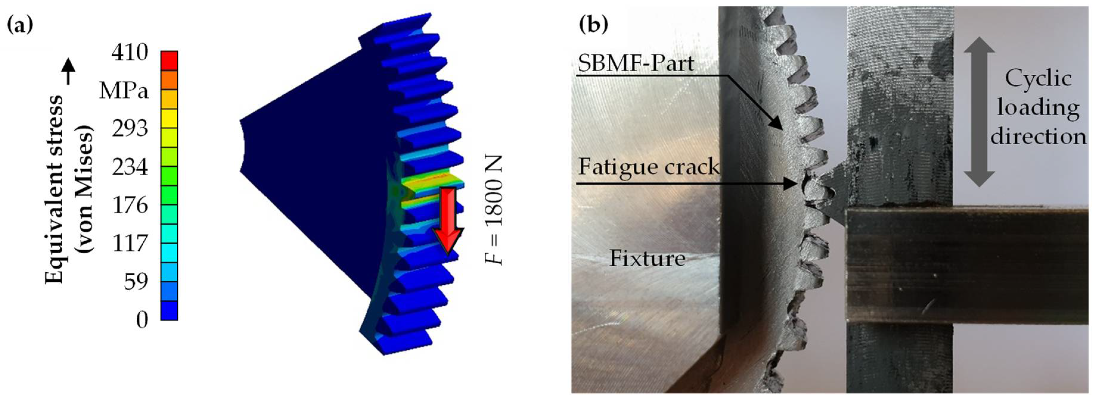
In the fatigue experiments, single teeth of the toothing were subjected to alternating loads. A test fixture was constructed that engaged one tooth and could be clamped in a universal testing machine, as shown in Figure 14. These experiments were performed employing force control at a frequency of 5 Hz. The tested components had a toothing height of 8.8 mm (corresponds to the overall z-height as shown in Figure 10) and were tested with load amplitudes between 900 N and 1800 N. In order to be able to plot the results in an SN-diagram, the resulting maximum tooth root stresses were calculated for these loads by a quasi-static simulation using the software Ansys, as exemplarily shown in Figure 14a. To estimate the equivalent stresses for the component, the cyclic stress–strain curves of the rolled material state shown in Figure 13 were used as the material data. The simulation yielded the largest equivalent stress in the area of the tooth root where the components in the tests also showed the occurrence of fatigue cracks, see Figure 14b.

4.4. Fatigue Life Prediction and Experimental Results

To calculate the fatigue life, the hysteresis loops recorded from the rolled material condition were evaluated and the corresponding values were used in Equation (4). For the crack propagation parameters, CJ = 6.4 × 10⁻⁹ mm/cycle and mJ = 1.48 were assumed. These values were determined in long-crack growth experiments on work-hardened DC04 and converted accordingly for the Z-integral approach [5]. These results corresponded to the expectations for low-alloy steels as reported in the literature [19].
The crack length at failure was set to af = 1 mm. To apply the fracture mechanics approach, crack growth starting from an initial crack length was assumed to occur in the first cycle. This initial crack length was considered to be in the order of the magnitude of microstructural defects such as ductile damage in the form of voids in the microstructure [20]. These voids are formed during the cold forming process and grow and coalesce to crack-like defects [21]. Several experiments on differently pre-loaded material states of DC04 steel have shown that these defects can have a size between a few nanometers up to more than 10 µm [22]. Furthermore, it could be shown that crack growth can indeed start from these defects [23]. In the present study, a mean initial crack length of a0 = 5 µm was chosen for the fatigue life calculation.
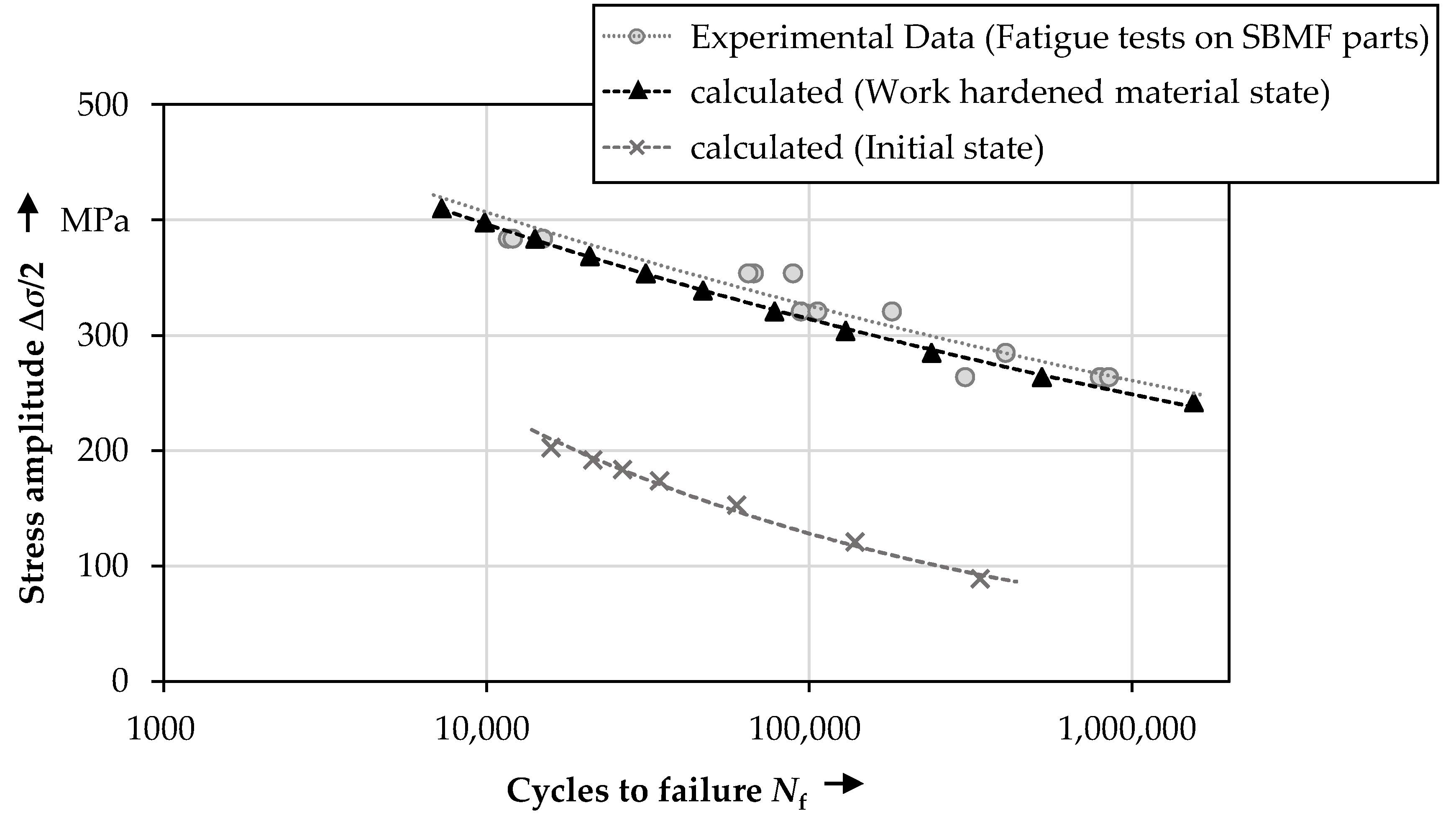
Employing these parameters, the calculated fatigue life corresponded well with the results of the fatigue experiments on individual teeth, as shown in Figure 15. For an optimal adaptation to the experimental results, a virtual initial crack length of about 2.5 µm could be determined by an inverse calculation. Thus, the crack length was in the range of microstructural defects, as they were caused by ductile damage. Here, performing further adaptions to the fatigue model was renounced, as the data available for an optimization were quite small. In general, the data points of the fatigue experiments (gray dots in Figure 15) showed a certain scattering, as was to be expected from the tests on the components. In this case, slight deviations of the mold filling or notches on the surface of the form elements had an influence on the fatigue life.
In order to evaluate the influence of work hardening due to the cold forming on the fatigue life, Figure 15 also shows a predicted SN-curve that resulted from the material data set for the DC04 in its initial state. Comparing the two material states, it can be seen that the bearable stresses could be approximately doubled. This shows that the work hardening due to the cold forming led to a significant increase in service life. Thus, it can be deduced that the performance in operation can be considerably increased by the forming process compared to manufacturing by, e.g., machining.

5. Data-Based Approach within SLASSY

In this section, the potential application of the findings from the previous chapters inside the engineering workbench SLASSY are shown. In the first paragraph, the functionality of the training of the metamodels based on the validated simulation data is described. The investigative part of this contribution is closed with a prediction of the analyzed component parameters and an optimization on the basis of the generated metamodels in order to generate a manufacturable part.

5.1. Metamodel Training

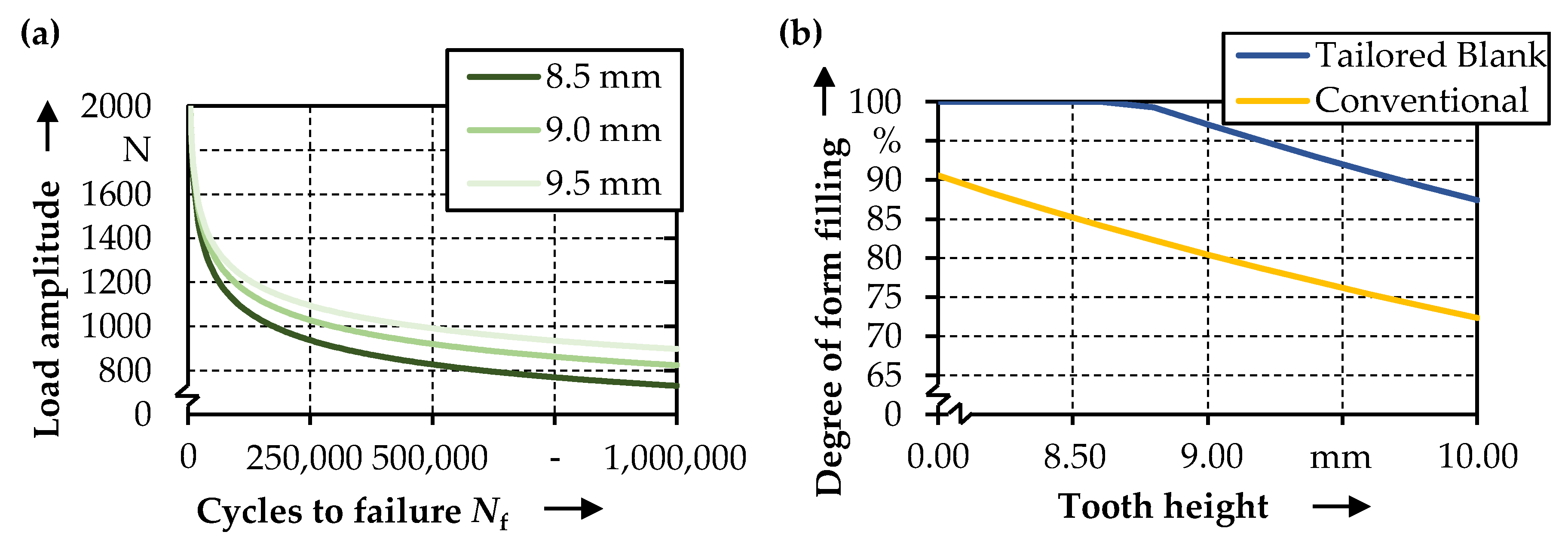
After the fatigue model was validated in the previous chapter and the findings regarding the degree of form filling were shown in Section 3, the tooth height could be identified as a relevant design parameter for the fatigue curve. To evaluate the influence of different parameter combinations, a simulation study was carried out as described in Section 4.3. Therefore, the tooth height was varied in five steps between 7 mm and 10 mm, also including the experimental result at 8.8 mm. These points could be used to train metamodels for the application inside SLASSY. Based on the five simulations carried out, the resulting load amplitude over cycles to failure was plotted and the resulting data points were extracted. These data were then stored inside a tabular dataset and used to train a metamodel. When a dataset was added for the first time for the training, the input (in this case, the tooth height) and targets (the load curve and the degree of form filling) had to be selected manually. Each time SLASSY was reopened, the initial dataset was checked for changes, and when new data were available, the model was trained with the updated dataset automatically. An exponential function showed the best potential to predict curves for arbitrarily selected tooth heights. After training, the metamodel was able to predict the resulting curve with an average coefficient of prognosis (CoP) [24] of 95.88% and a root mean squared error (RMSE) of ±85.7 N. A possible prediction of the trained metamodel for the resulting fatigue curve for a selected tooth height of 9.0 mm and two curves for the neighboring tooth heights with ±0.5 mm are shown in Figure 16a. To predict the degree of form filling, a dataset of tooth heights ranging between 8 mm and 10 mm and the resulting degree of form filling for a conventional blank, as well as for a tailored blank, was used. The results of chapter 3 were collected and stored inside SLASSY’s database. For the prediction of the degree of form filling, a decision tree regressor [25] was used within the metamodel, which basically consisted of an ensemble of linear models and was able to predict the data points with a coefficient of prognosis of 97.85% and a root mean squared error of ±2.05% for the degree of form filling. Both prediction qualities were estimated using an 80/20 train-test-split [26], which indicated an 80% use of the datapoints for training and 20% for the testing and evaluation of CoP and RMSE. Figure 16b shows the prediction of the degree of form filling for the conventional and the tailored blank. Lastly, the data and the metamodels were stored in tabular form inside SLASSY’s own SQL-based database. This is mandatory for subsequent retrieval and application.

5.2. Application inside SLASSY

In order to use the generated data for the evaluation of the geometrical parts, as shown exemplarily in Figure 2, a final analysis step inside SLASSY was required. With this step, the prediction of resulting product properties, for example, the load curve or the degree of form filling from known or given product characteristics (tooth height) was now possible [27]. For this step, the described metamodels were implemented into the database and the properties were displayed in the analysis table. As shown in Figure 2, the current geometric parameters such as the tooth height were transmitted into SLASSY directly from the CAD system; in the presented case, Dassault Systèmes CATIA V5-6R2013x. Afterwards, the database was then able to predict the resulting curve and degree of form filling in the analysis step. This was set up via a bidirectional interface described in [6]. The resulting curves and the degree of form filling could then be presented to the product developers via datasheets or plots, as in Figure 16.
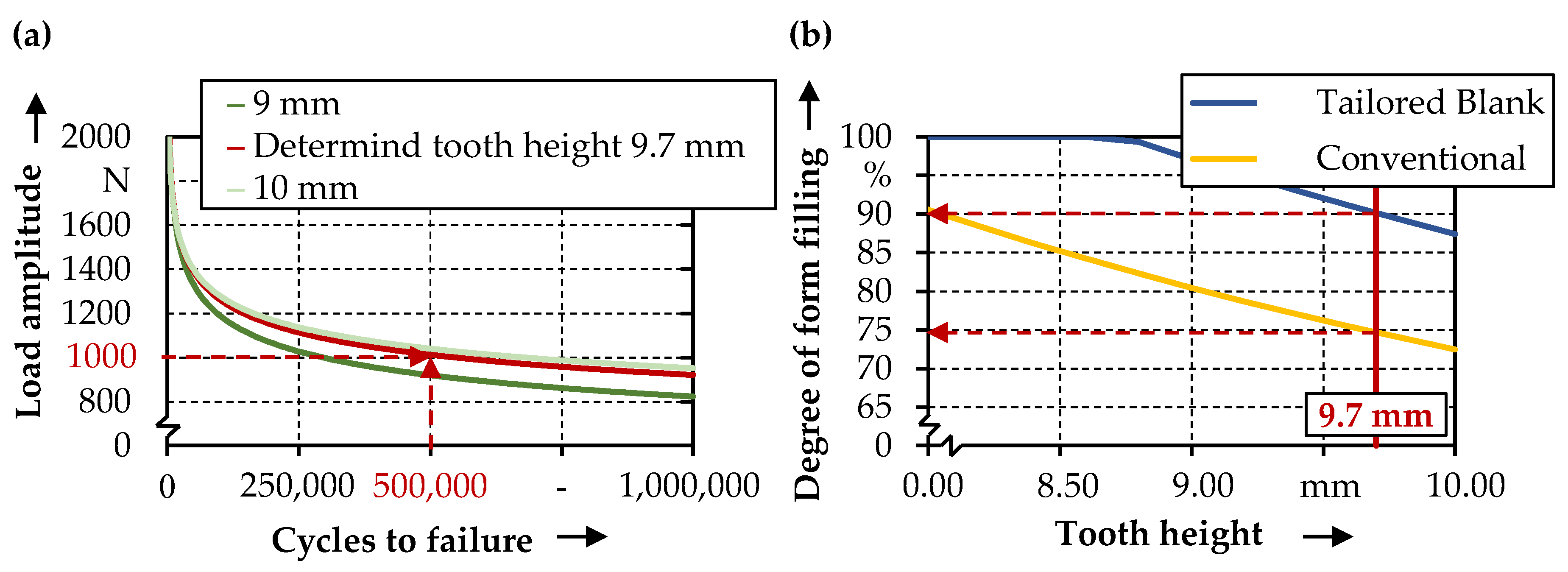
With the presented data-driven approach, it was possible to use the generated data inside SLASSY to optimize the current part design, regarding an ideal degree of form filling or fatigue life requirements with implemented optimization algorithms, as shown in [28]. By selecting a desired value of the investigated parameter, the data-driven approach enabled the determination of the respective geometrical parameters, as exemplarily shown in Figure 17a. For example, 1000 N was selected for a desired maximum load amplitude, and the minimum number of cycles to failure had to be 500,000. Thus, the tooth height was predicted at a value of 9.7 mm by the trained metamodels. As shown in Figure 17b, the degree of form filling only reached 74.7% using a conventional blank. In this case, for the previously described parameter combination, SLASSY could predict that a conventional blank was not feasible for realizing an acceptable degree of form filling. However, the system suggested the application of a tailored blank in the investigated process in order to reach an acceptable degree of form filling of 90.1%.

6. Discussion

Within this contribution, a fundamental process understanding of the combined deep drawing and upsetting process for manufacturing thin-walled functional components with circumferential gearing could be generated. In particular, the influence of the use of different semi-finished products on the forming results were investigated. Using a conventional blank made out of the mild deep drawing steel DC04, the material volume provided in the area of the later cup wall was not sufficient to allow a proper filling of the cavity, hence only reaching a maximum of 86%. Consequently, process failures such as buckling and folding could be detected, thus contributing to the results in [9] for a different geometry. An increasing material strength due to cold hardening during the forming operation represented another limiting factor for realizing the desired geometry, reaching an average of 233.4 ± 30.1 HV0.05, thus showing an increase of 87% compared to the initial hardness and revealing an inhomogeneous distribution across the cup wall, referring to the high standard deviation. In this context, the control of the material flow could be identified as a major challenge [4]. In order to increase the degree of form filling by adjusting the material flow into the cavity and to prevent the process failures, a new process strategy was applied. By using process-adapted semi-finished parts with a local material pre-distribution, the material could be provided in the required areas. Due to further available material volume, the form filling of the component could be increased up to 98%. The evaluation of the hardness distribution revealed a decreased average hardness value of 220.3 ± 22.9 HV0.05, thus supporting the material flow due to a reduced strength compared to the conventional blank. Furthermore, the homogeneity of the formed tooth in form of the standard deviation could be increased significantly, and the process failures could be prevented, thus confirming the results in [8]. The components manufactured out of a tailored blank offered the highest values for the degree of form filling, thus being identified as the most applicable for the subsequent investigation of the fatigue life.
To consider the performance of the components already in the design phase, the data of a fatigue model were provided for the SLASSY workbench. Therefore, the fatigue properties of the component could be simulated by means of a work-hardened material state that featured almost the same hardness as the components’ toothing. Assuming an initial crack length of 5 µm, a good agreement of the calculated fatigue life with the results of fatigue experiments could be achieved. Furthermore, the improvement of the fatigue properties due to the cold forming was shown here in comparison with a further data set for the material condition of the DC04 steel as received. By extending these data by further degrees of deformation as presented in [5], the fatigue model could be used to calculate a fatigue life prognosis for any work-hardened material state after forming. Implemented in the SLASSY workbench, this enabled the calculation of a fatigue life prognosis for any part geometry, considering the hardness of the respective form element after the forming process.
In order to implement the generated data into the workbench, a data-driven approach was applied. In this context, an exponential function for the prediction of the resulting curves for a given tooth height could be identified as the most promising approach regarding the prediction quality. For predicting the degree of form filling of either conventional or tailored blank designs, a decision tree regressor could be classified as sufficient, regarding the root mean squared error and the coefficient of prognosis. The presented metamodels were mathematical constructs to inter- or extrapolate between the data points, created in the simulation and experimental studies described previously. For this representation, it was possible to predict the resulting values for a selected input value, in this case, the tooth height. Moreover, both models showed acceptable prediction qualities for general usage, as their values of the coefficient of prognosis were well above 90%, and the root mean squared error was orders of magnitude lower than the total value. The presented methods offer the potential for application to various processes and different geometries within sheet-bulk metal forming, as previously presented in [6]. Based on the simulations and experimental studies, the presented metamodels can be used to optimize a given part design regarding its manufacturing properties inside SLASSY. For example, the values for optimization can be the degree of form filling or the desired load amplitude and cycles to failure. These metamodels can also be used in the context of rapid prototyping to generate different design alternatives for product developers. The presented methods can be applied to all different tooth and part designs within the context of sheet-bulk metal forming. To create metamodels for other geometries, the desired process or geometry parameter must be investigated for the respective geometry. Furthermore, the fatigue-life-model needs to be updated regarding the part design.

7. Conclusions

In this contribution, a fundamental analysis of the mechanical properties of components manufactured by sheet-bulk metal forming processes was carried out. To determine the fatigue life, a fatigue model was presented and validated by cyclic experiments on the functional form elements of the components. To allow the synthesis between the geometrical and mechanical properties of the parts, the self-learning engineering workbench SLASSY was trained with the help of metamodels to calculate the maximum achievable form filling, as well as the fatigue life, on the example of different component heights.
The main conclusions of this research can be summarized as follows:
  • A process combination of deep drawing and upsetting within sheet-bulk metal forming can be used to manufacture cup-like components with circumferential involute gearing. However, process failures in the form of folding and buckling were identified during the evaluation of the geometrical and mechanical properties. Since the required material volume in the area of the gearing was not sufficient, possibilities to enlarge the form filling are required.
  • By applying orbital formed semi-finished parts in the investigated process combination of deep drawing and upsetting, the maximum form filling can be increased significantly by up to 98%. Furthermore, the process failures can be prevented, and the homogeneity of the hardness distribution outlines the improved forming results.
  • The fatigue life of the components can be described well by employing the Z-integral approach. The mechanical properties of the sheet-bulk metal formed material state can be approximated by analyzing a similarly work-hardened state produced by rolling.
  • With an assumed initial crack length of 5 µm, the fatigue life is predicted well. By an inverse calculation, the virtual initial crack length was determined to be about 2.5 µm for an optimal fit to the experimental results. With these values, the initial crack length is in the range of the size of microstructural defects such voids that occur due to ductile damage.
  • The comparison of the predicted SN-curves for the initial state and the work-hardened material state shows that the fatigue life of the SBMF-components is significantly increased due to work hardening. This shows an advantage of the forming process compared to other manufacturing processes.
  • The findings regarding fatigue life could be modeled with the aid of exponential function based metamodels to allow for the prediction of arbitrarily selected part design parameters. The prediction quality is within an acceptable range, as it has shown a coefficient of prognosis of around 95%.
  • Moreover, the degree of form filling could be modeled, allowing for the prediction of different selected part design parameters. This data-driven approach allows for further investigations with different part designs or form elements.
In order to evaluate the transferability of the fatigue model used in combination with the data-driven approach of the workbench, further research should focus on the investigation of different geometries in the context of sheet-bulk metal forming. Furthermore, the database could be expanded by the application and evaluation of different material classes and strength levels within the presented setup.

Author Contributions

Conceptualization, A.H., R.S., M.V., M.L., H.-B.B., H.J.M., C.S., B.S., S.W. and M.M.; methodology, A.H., M.L., H.-B.B. and C.S.; software, A.H., H.-B.B. and C.S.; validation, A.H., H.-B.B. and C.S.; formal analysis, M.L., H.J.M., B.S., S.W. and M.M.; investigation, A.H., R.S., M.V. and H.-B.B.; resources, H.J.M., S.W. and M.M.; data curation, A.H., H.-B.B. and C.S.; writing—original draft preparation, A.H., R.S., M.V., H.-B.B. and C.S.; writing—review and editing, M.L., H.J.M., B.S., S.W. and M.M.; visualization, A.H., R.S., M.V., H.-B.B. and C.S.; supervision, M.L., H.J.M., B.S., S.W. and M.M.; project administration, M.L. and M.M.; funding acquisition, M.M. All authors have read and agreed to the published version of the manuscript.

Funding

This work is funded within the scope of the Transregional Collaborative Research Centre TCRC73 by the German Research Foundation under Grant number TRR73-68237143.

Institutional Review Board Statement

Not applicable.

Informed Consent Statement

Not applicable.

Data Availability Statement

The related data generated and analyzed for the contribution is available from the corresponding author on request. The related code for the metamodels, used within the workbench, is available from C. Sauer on request.

Acknowledgments

This study was supported by the German Research Foundation (DFG) within the scope of the Transregional Collaborative Research Centre on Sheet-Bulk metal forming (TCRC 73). It has been realized in particular with the help of the subprojects A1, B1, C6, and T02. Furthermore, special thanks go to the research group “Component Properties and Function” which is also active in the context of the TCRC 73 research compound.

Conflicts of Interest

The authors declare no conflict of interest.

References

  1. Kishawy, H.; Hegab, H.; Saad, E. Design for Sustainable Manufacturing: Approach, Implementation, and Assessment. Sustainability 2018, 10, 3604. [Google Scholar] [CrossRef] [Green Version]
  2. Gumpinger, T.; Jonas, H.; Krause, D. New Approach for Lightweight Design: From Differential Design to Integration of Function. In Proceedings of ICED 09, the 17th International Conference on Engineering Design, 6th ed.; Norell Bergendahl, M., Grimheden, M., Leifer, L., Skogstad, P., Lindemann, U., Eds.; Stanford University: Palo Alto, CA, USA, 2009; pp. 201–210. [Google Scholar]
  3. Mori, K.; Nakano, T. State-of-the-art of plate forging in Japan. Prod. Eng. Res. Dev. 2016, 10, 81–91. [Google Scholar] [CrossRef]
  4. Gröbel, D.; Schulte, R.; Hildenbrand, P.; Lechner, M.; Engel, U.; Sieczkarek, P.; Wernicke, S.; Gies, S.; Tekkaya, A.E.; Behrens, B.-A.; et al. Manufacturing of functional elements by sheet-bulk metal forming processes. Prod. Eng. Res. Dev. 2016, 10, 63–80. [Google Scholar] [CrossRef]
  5. Besserer, H.-B.; Nürnberger, F.; Maier, H.J. Fatigue Behavior of Sheet-Bulk Metal Formed Components. In Sheet Bulk Metal Forming; Merklein, M., Tekkaya, A.E., Behrens, B.-A., Eds.; Springer: Cham, Switzerland, 2021; pp. 412–433. [Google Scholar] [CrossRef]
  6. Sauer, C.; Schleich, B.; Wartzack, S. Simultaneous Development of a Self-learning Engineering Assistance System. In Sheet Bulk Metal Forming; Merklein, M., Tekkaya, A.E., Behrens, B.-A., Eds.; Springer: Cham, Switzerland, 2021; pp. 127–146. [Google Scholar] [CrossRef]
  7. Simpson, T.W.; Peplinski, J.D.; Koch, P.N.; Allen, J.K. Metamodels for Computer-based Engineering Design: Survey and recommendations. Eng. Comput. 2001, 17, 129–150. [Google Scholar] [CrossRef] [Green Version]
  8. Vogel, M.; Schulte, R.; Lechner, M.; Merklein, M. Process Combination for the Manufacturing of Toothed, Thin-Walled Functional Elements by Using Process Adapted Semi-finished Products. In Sheet Bulk Metal Forming; Merklein, M., Tekkaya, A.E., Behrens, B.-A., Eds.; Springer: Cham, Switzerland, 2021; pp. 1–29. [Google Scholar] [CrossRef]
  9. Magrinho, J.P.; Silva, M.B.; Martins, P.A.F. Injection by sheet-bulk forming. Precis. Eng. 2019, 59, 73–80. [Google Scholar] [CrossRef]
  10. Behrens, B.-A.; Tillmann, W.; Biermann, D.; Hübner, S.; Stangier, D.; Freiburg, D.; Meijer, A.; Koch, S.; Rosenbusch, D.; Müller, P. Influence of Tailored Surfaces and Superimposed-Oscillation on Sheet-Bulk Metal Forming Operations. J. Manuf. Mater. Process. 2020, 4, 41. [Google Scholar] [CrossRef]
  11. Wernicke, S.; Thier, U.; Hahn, M.; Tekkaya, A.E. Controlling material flow in incremental sheet-bulk metal Forming by thermal grading. Procedia Manuf. 2020, 50, 257–264. [Google Scholar] [CrossRef]
  12. Hetzel, A.; Lechner, M. Orbital Forming of Tailored Blanks for Industrial Application. In Sheet Bulk Metal Forming; Merklein, M., Tekkaya, A.E., Behrens, B.-A., Eds.; Springer: Cham, Switzerland, 2021; pp. 458–476. [Google Scholar] [CrossRef]
  13. Kopp, R.; Wiedner, C.; Meyer, A. Flexibly Rolled Sheet Metal and Its Use in Sheet Metal Forming. Adv. Mater. Res. 2005, 6–8, 81–92. [Google Scholar] [CrossRef]
  14. Lucas, H.; Denkena, B.; Grove, T.; Krebs, E.; Freiburg, D.; Biermann, D.; Kersting, P. Analysis of Residual Stress States of Structured Surfaces Manufactured by High-Feed and Micromilling. J. Heat Treat. Mater. 2015, 70, 183–189. [Google Scholar] [CrossRef]
  15. Dowling, N.; Begley, J. Fatigue Crack Growth During Gross Plasticity and the J-Integral. In STP590-EB Mechanics of Crack Growth; Rice, J., Paris, P., Eds.; ASTM International: West Conshohocken, PA, USA, 1976; pp. 82–103. [Google Scholar] [CrossRef]
  16. Wüthrich, C. The extension of the J-integral concept to fatigue cracks. Int. J. Fract. 1982, 20, 35–37. [Google Scholar] [CrossRef]
  17. Heitmann, H. Betriebsfestigkeit von Stahl: Vorhersage der technischen Anrisslebensdauer unter Berücksichtigung des Verhaltens von Mikrorissen. Ph.D. Thesis, RWTH Aachen University, Aachen, Germany, 1983. [Google Scholar]
  18. Heitmann, H.; Vehoff, H.; Neumann, P. Life prediction for random load fatigue based on the growth behaviour of microcracks. In Advances of Fracture Research; Valluri, S.R., Ed.; Pergamon Press: Oxford, UK, 1985; pp. 3599–3606. [Google Scholar]
  19. Haibach, E. Betriebsfestigkeit. Verfahren und Daten zur Bauteilberechnung; Springer: Berlin, Germany, 2006. [Google Scholar] [CrossRef]
  20. Tekkaya, A.E.; Bouchard, P.-O.; Bruschi, S.; Tasan, C.C. Damage in metal forming. CIRP Ann. 2020, 69, 600–623. [Google Scholar] [CrossRef]
  21. Goods, S.H.; Brown, L.M. Overview No. 1: The nucleation of cavities by plastic deformation. Acta Metall. 1979, 27, 1–15. [Google Scholar] [CrossRef]
  22. Gerstein, G.; Besserer, H.-B.; Nürnberger, F.; Maier, H.J. Comparison of the mechanisms of void formation by plastic deformation in single- and dual phase steels. In Proc. TMS Annual Meeting 2015. Characterization of Minerals, Metals, and Materials; Carpenter, J., Bai, C., Pablo Escobedo-Diaz, J., Hwang, J.-Y., Ikhmayies, S., Li, B., Li, J., Neves, S., Peng, Z., Zhang, M., Eds.; Wiley: Hoboken, NJ, USA, 2015; pp. 75–81. [Google Scholar]
  23. Besserer, H.-B.; Hildenbrand, P.; Gerstein, G.; Rodman, D.; Nürnberger, F.; Merklein, M.; Maier, H.J. Ductile damage and fatigue behavior of semi-finished tailored blanks for sheet-bulk metal forming processes. J. Mater. Eng. Perform. 2016, 25, 1136–1142. [Google Scholar] [CrossRef]
  24. Most, T.; Will, J. Metamodel of Optimal Prognosis-an automatic approach for variable reduction and optimal metamodel selection. Proc. Weimarer Optim. Stochastiktage 2008, 5, 20–21. [Google Scholar] [CrossRef]
  25. Breiman, L.; Friedman, J.H.; Olshen, R.A.; Stone, C.J. Classification and Regression Trees; Wadsworth Inc.: New York, NY, USA, 1984. [Google Scholar]
  26. Hastie, T.; Tibshirani, R.; Friedman, J. The Elements of Statistical Learning, 2nd ed.; Springer: New York, NY, USA, 2017. [Google Scholar] [CrossRef]
  27. Weber, C. An extended theoretical approach to modelling products and product development processes. Proc. 2nd Ger. Isr. Symp. Adv. Methods Syst. Dev. Prod. Process. 2005, 2, 159–179. [Google Scholar]
  28. Küstner, C.; Beyer, F.; Kumor, D.; Loderer, A.; Wartzack, S.; Willner, K.; Blum, H.; Rademacher, A.; Hausotte, T. Simulation-based Development of Pareto-optimized Tailored Blanks for the use within Sheet-Bulk Metal Forming. In Proceedings of the DESIGN 2016 14th International Conference; Marjanović, D., Storga, M., Pavković, N., Bojcetic, N., Skec, S., Eds.; Design Society: Dubrovnik, Croatia, 2016; pp. 291–300. [Google Scholar]
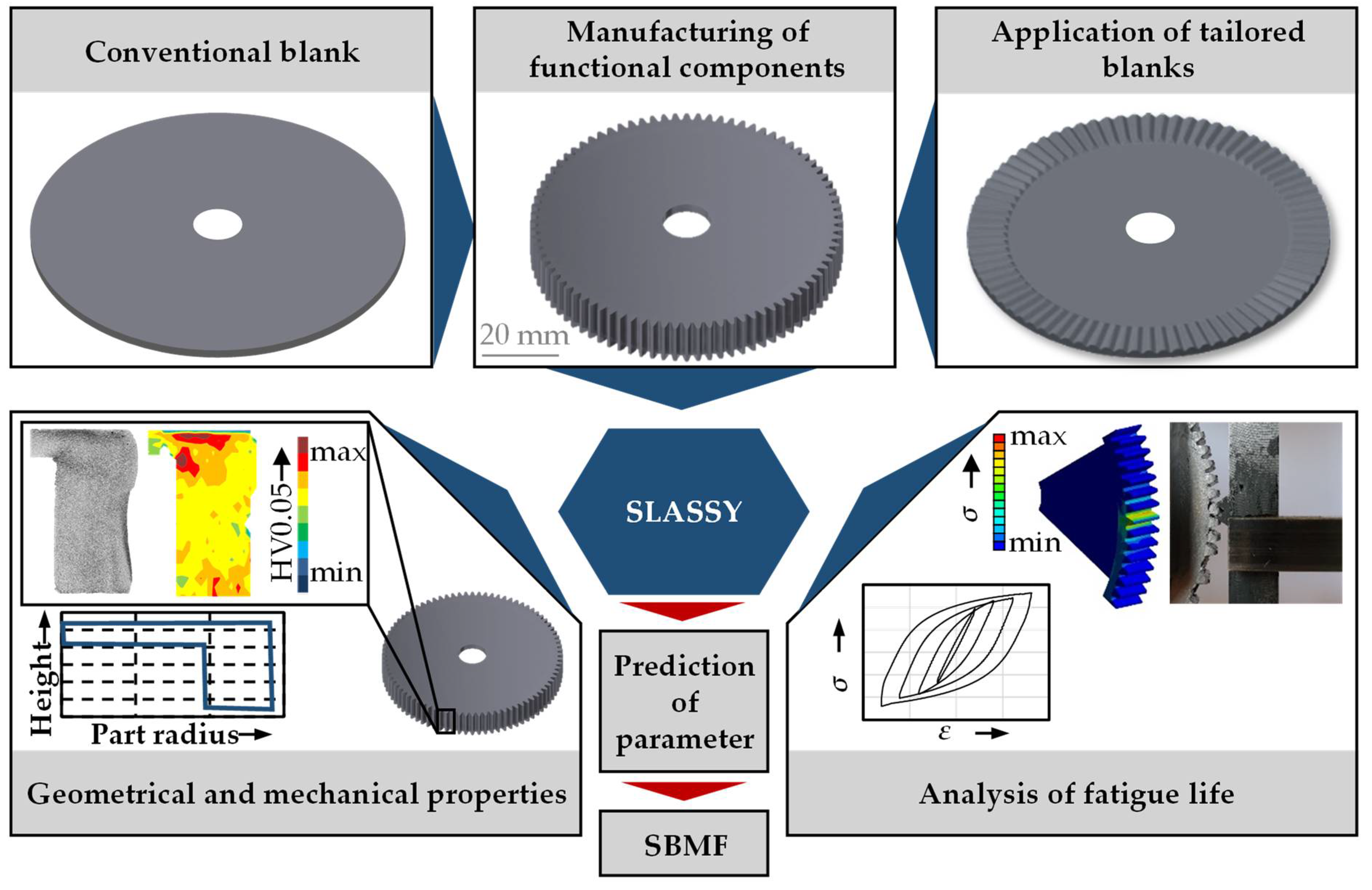
Figure 1. Applied methodology within the present contribution.
Jmmp 05 00049 g001
Figure 2. Part design and the synthesis step within SLASSY.
Jmmp 05 00049 g002
Figure 3. Investigated component geometry.
Jmmp 05 00049 g003
Figure 4. Material characterization of DC04 [4].
Jmmp 05 00049 g004
Figure 5. Schematic setup of the combined deep drawing and upsetting process [8].
Jmmp 05 00049 g005
Figure 6. Experimental results obtained with a conventional blank.
Jmmp 05 00049 g006
Figure 7. (a) Process setup and (b) characteristics of orbital forming [4].
Jmmp 05 00049 g007
Figure 8. Process setup of flexible rolling [8].
Jmmp 05 00049 g008
Figure 9. Average sheet thicknesses for the orbital forming and flexible rolling processes for different geometries.
Jmmp 05 00049 g009
Figure 10. Experimental results obtained with the investigated tailored blank layout.
Jmmp 05 00049 g010
Figure 11. (a) Specimen geometry and orientation, (b) test setup of the strain-controlled fatigue experiments.
Jmmp 05 00049 g011
Figure 12. Hysteresis loops for the (a) initial state and (b) the rolled material state.
Jmmp 05 00049 g012
Figure 13. Cyclic stress–strain curves determined for the initial and rolled material state, compiled from [5].
Jmmp 05 00049 g013
Figure 14. (a) Calculated von Mises stress for a service load of 1800 N and (b) the test setup for the fatigue tests.
Jmmp 05 00049 g014
Figure 15. S-N-curves determined for the different material states.
Jmmp 05 00049 g015
Figure 16. (a) Resulting curves for different tooth heights predicted by the trained metamodel, and (b) the predicted degree of form filling for a conventional and a tailored blank.
Jmmp 05 00049 g016
Figure 17. (a) Prediction of tooth height for given cycles to failure and load amplitude and (b) the respective degree of form filling for conventional and tailored blanks, evaluated by the trained metamodels.
Jmmp 05 00049 g017
Publisher’s Note: MDPI stays neutral with regard to jurisdictional claims in published maps and institutional affiliations.