Article

An Agent-Based System for Automated Configuration and Coordination of Robotic Operations in Real Time—A Case Study on a Car Floor Welding Process

Laboratory for Manufacturing Systems and Automation, Department of Mechanical Engineering and Aeronautics, University of Patras, 26500 Patras, Greece
*
Author to whom correspondence should be addressed.
J. Manuf. Mater. Process. 2020, 4(3), 95; https://doi.org/10.3390/jmmp4030095
Submission received: 31 July 2020 / Revised: 31 August 2020 / Accepted: 15 September 2020 / Published: 18 September 2020
(This article belongs to the Special Issue Cyber Physical Production Systems)

Abstract

:
This paper investigates the feasibility of using an agent-based framework to configure, control and coordinate dynamic, real-time robotic operations with the use of ontology manufacturing principles. Production automation agents use ontology models that represent the knowledge in a manufacturing environment for control and configuration purposes. The ontological representation of the production environment is discussed. Using this framework, the manufacturing resources are capable of autonomously embedding themselves into the existing manufacturing enterprise with minimal human intervention, while, at the same time, the coordination of manufacturing operations is achieved without extensive human involvement. The specific framework was implemented, tested and validated in a feasibility study upon a laboratory robotic assembly cell with typical industrial components, using real data derived from a car-floor welding process.

1. Introduction

Shorter product lifecycles along with the need for more products and product variants put a lot of pressure on manufacturing companies to reduce their product development phase and decrease production costs while keeping high quality standards and sufficient production quantities. The consequences of these trends make flexibility, re-configurability and robustness key attributes in today’s global manufacturing environment [1].
The research work regarding the efficient reconfiguration, control and coordination of production equipment in manufacturing environments has evolved very rapidly in the recent past. However, in order to reach the goal of resilient, self-configured and self-optimized Cyber Physical Systems (CPS) being realized in industrial practice, further study is required. According to [2], the following areas need to be addressed in order to achieve a higher degree of intelligent self-reconfiguration in manufacturing systems:
  • Intelligent components and architectures that support the vertical integration of the component-level agents with higher-level systems.
  • Reconfiguration services that will enable more autonomy in the (re)configuration process.
  • Fault diagnosis and recovery.
  • Safety.
In this context, ontology-based knowledge acquisition and factual inference as well as multi-agent technology are well perceived as key enablers for the autonomous control of highly fault tolerant and reconfigurable manufacturing systems.
The approach utilizes ontology as a formal means of expressing the system’s possible valid states. Through such an approach, the significance of the discussed approach can be summarized as:
  • The combination of ontology for representing knowledge in manufacturing automation systems—together with the multi-agent approach to enable, in real time, the automated configuration/reconfiguration, control and coordination of manufacturing operations.
  • The reduction of the programming complexity required to coordinate heterogenous systems and the lower expertise required by the technical personnel.
  • The ability of production systems to reconfigure their operation with minimal intervention, reducing downtime and associated costs significantly.
The remaining part of Section 1 has to do with the relevant literature and presents an overview of the selected case study. Section 2 describes the architecture and the details of the multi-agent system as well as the ontology-based mechanism for the coordination of executing robotic operations. The method suggested is applied to a pilot implementation in Section 3. Finally, Section 4 provides some conclusions on the work presented in this paper as well as the outlook for future research work.

1.1. Literature Review

The literature survey revealed three streams that are highly relevant to the work discussed in the paper. These are agent-based manufacturing, service-oriented architecture and ontology.
The work in [3] has defined Multi Agent System (MAS) as a set of agents that are able to represent the objects within a system that can interact with each other, with the aim of achieving their individual goals, especially in cases where they possess little knowledge and/or skills. For a long time, software agents have been considered as a key technology for manufacturing-control applications, thanks to their operating principle, which relies on distributed architectures. This allows them to be designed in a way that decentralizes the control of the manufacturing systems, promoting the reduction of complexity along with enhanced flexibility. In the scope of MAS, heuristic approaches are used for planning and optimization, including, but not limited to, genetic algorithms, neural networks and fuzzy logic [4]. Algorithms implementing agent-based control and MAS exhibit major benefits such as robustness, application feasibility flexibility and redeployability [5,6]. Nevertheless, the adoption of the agent-based approach in industrial applications has been held back by issues related to the interfacing, synchronization and data consistency with existing information systems. To a certain extent, agents have been applied to address challenges related to the real-time control of customized mass production [7].
In [8], there is a description of a scheduling method in which a negotiation process for decision-making, among multiple agents, is used instead of pre-planned processes. In [9], a negotiation-based control approach is proposed to address variability within a production system, where the involved agents are able to perform their operation in direct communication and interaction with each other. A self-reactive, cloud-based, multi-agent architecture is presented in [10] to enable the subscribed agents, clients and production entities to exchange information in real time. In [11], they presented an agent-based method for dealing with decision-making tasks in a decentralized manufacturing environment; their method was implemented into software, which was deployed within the premises of a textile production plant. The PRIME framework presented in [12] adopts a MAS approach that can implement the reconfiguration of a production system by supporting plug and produce, and inherent monitoring capabilities for heterogeneous systems. In [13], a large number of MAS patterns were compared, leading to the conclusion that they could greatly benefit the Cyber-Physical-Production-System (CPPS) design. In the same work, it was discussed that production that is based on MAS is an efficient approach to handling the complexity of CPPS development.
Service Oriented Architecture (SOA) concepts are used for facing the problems of interoperability in autonomous multi-agent systems. The SOA approach utilizes services as fundamental elements, enabling platform-independent implementation. When using the SOA approach, the controller of each smart device, such as a robot, vision element or material-handling element, encapsulates the functions that the actual device can carry out, also including the services that it can provide (e.g., moving the robot along a trajectory). Such services can be updated, added or deleted and are available to be called by the controllers of other smart devices. A Service-Oriented integration architecture relying on agents was introduced by [14] to provide scheduling services for virtual enterprises operating under a common network. In [15], they proposed agent-based smart manufacturing objects, at that time being managed through Universal Description, Discovery and Integration (UDDI), which is able to provide capabilities including registering, publishing, binding and invoking. Service Oriented Architecture (SOA), in the field of industrial automation devices, is mainly implemented by OASIS’s Devices Profile for Web Services (DPWS) as well as the OPC Unified Architecture (OPC UA) [16]. DPWS is a set of specification constraints for secure Web Service messaging, discovery, description and “eventing” on resource-constrained devices. OPC-UA is probably the dominant communication technology for the factory-floor era, as it provides unified communication and interaction, especially when it comes to linking Programmable Logic Controller (PLC) and sensor data with existing Supervisory Control and Data Acquisition (SCADA) and Manufacturing Execution Systems (MES). In the field of robotics applications, the Robot Operating System (ROS) is another implementation option to be considered for implementing SOA. As in the case of web services and their “request” and “response” documents, which are defined by Universal Resource Locators (URIs), a ROS service is also defined by its name and the relevant request/response messages.
As far as knowledge management and exchange is concerned, typical multi-agent architectures may be considered to be implicit and stiff (e.g., [17]). A critical deficiency is that the interpretation of the messages received is not explicit but is strongly encapsulated in the core code of each agent. This further complicates the system’s expansion and the incorporation of additional agents, since it would dictate that existing agents are reprogrammed to acknowledge and handle the new entities and states. To address these problems and to allow MAS to process knowledge in an automatic way so that inference of facts can be enabled, it has been proposed that multi-agent systems be extended with semantics. The semantics are often captured by an ontology. An extensive presentation of how ontologies have been applied in agent-based control applications is presented in [18] along with a discussion on the commonalities between the different integration approaches. The reason for the ontology’s integration with multi-agent systems is that the explicit expression of agent semantics will enable them to operate differently when the knowledge base changes, apart from enabling the integration of new agents without the need to modify the code of the existing ones. Several studies have been conducted on the issue of representing the manufacturing systems using a modelling language along with the tasks that are performed by this system. One approach reported in [19] is using the Unified Modeling Language (UML) to describe the manufacturing system.
Another approach presented in [20], suggests the automatic initialization of each agent with a pre-created knowledge-base relying on semantic web technologies. Such an approach allows specification consistency checks and more efficient communication that is focused on aspects requiring real-time handling. In [21], they present scalable and flexible agent-based manufacturing systems whose production plan is created by autonomous agents that exploit a semantic description of web-based artifacts. Reinhart and Krug [22] proposed an approach that transfers the robots’ configuration and control information to a Configuration Manager, where a state model is synthesized. In [23,24], a manufacturing ontology structure is proposed and includes four different aspects of automation systems: the (i) resource structure, (ii) process structure, (iii) product structure and (iv) production-order structure. In [25], they presented an interesting approach to an automated configuration/reconfiguration of control software. In this work, the knowledge base is used to represent equipment-related information, including low-level functions as well as the relations to other entities. However, it does not support information regarding any other important manufacturing parameters, such as production requirements and process-monitoring data, required in order for coherent situation awareness, concerning all the manufacturing components operating in the region of interest being maintained. In [26], an approach to designing modular assembly systems using ontologies is described and presented as a key enabling technology, Evolvable Assembly Systems (EAS). In a similar manner, an ontology-based agent with intelligent reasoning capabilities was used to enable the adaptive behavior of the production system against dynamic changes in the manufacturing requirements [27]. However, in their approach, the reconfiguration agent was not integrated with the embedded controllers. In [28], they presented an ontology-based model for the abstraction of equipment and components as a way of enabling interaction between them and achieving a “plug and produce” functionality.

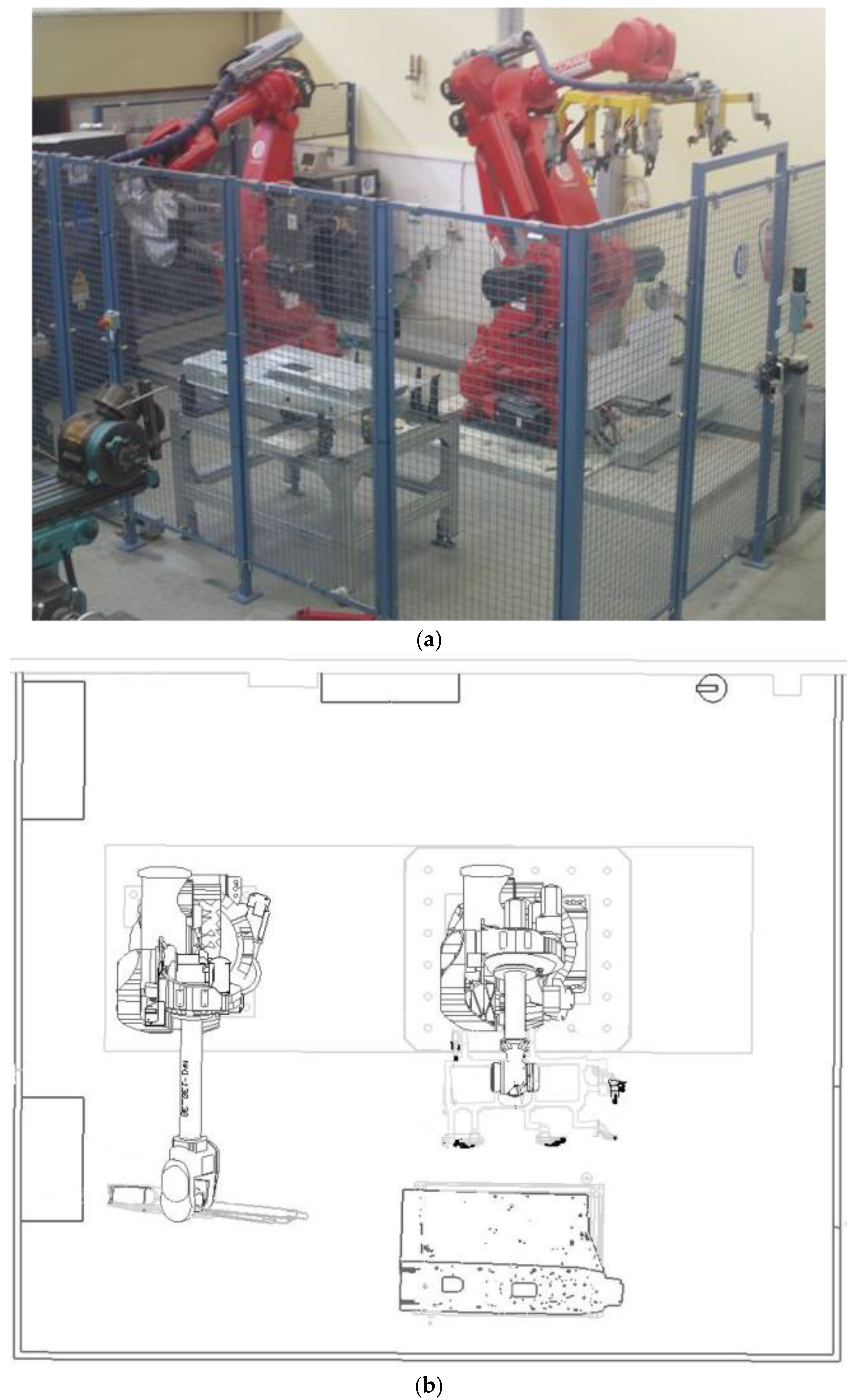
1.2. Case Study Overview and Technology Selection

The approach proposed in this work is applied in a case study that involves the automated configuration and real-time coordination of robotic operations for the welding of a car floor. A laboratory robotic assembly cell with typical industrial components and the use of real process data from the automotive industry is considered. This robotic assembly cell consists of two commercial robots, which are used to perform spot welding on passenger-vehicle floor parts. The layout of the assembly cell is depicted in Figure 1. The cell comprises the following robots:
  • A Comau Smart NJ 130, which is equipped with a spot-welding gun (robot depicted on the left-hand side of Figure 1b).
  • A Comau Smart NJ 370, which uses a semi-flexible gripper that can hold both parts simultaneously (robot depicted on the right-hand side of Figure 1b). The gripper is able to accommodate two variants of the vehicle floor, which differ in geometry but have common grasping points. The use of sensors to identify the grasped parts allows the gripper to adjust its behavior by actuating specific clamping units each time.
Moreover, a loading table is included in the cell (as shown at the bottom of Figure 1b) for assisting the loading and unloading of parts.
The following process scenario is executed in the cell, and it is supported by the multi-agent framework proposed in this study. The scenario involves the welding of a car floor as follows:
  • The operator loads the parts of the floor on a loading table, which is located in the working area of the robots. The table is designed to provide adequate tolerance with respect to the positioning of the accommodated parts.
  • The handling Robot simultaneously picks up all the parts from the loading table by using a geo-gripper that can guarantee relative positioning accuracy and adequate grasping forces through simple pneumatic clamps that are controlled through an Input/Output (I/O) module. It allows the final product’s correct geometry to be achieved.
  • Inductive sensors mounted onto the gripper perform presence detection for the part throughout the execution of the welding operation.
  • The operation of the robots is cooperative in the sense that:
    • The handling robot manipulates the part in midair in order to achieve orientations that maximize the accessibility of the welding gun to all spot0weld locations.
    • The proposed framework is used to orchestrate the communication between the two robots, which are able to exchange content-rich messages to declare the start/end/progress of each task that they are executing.
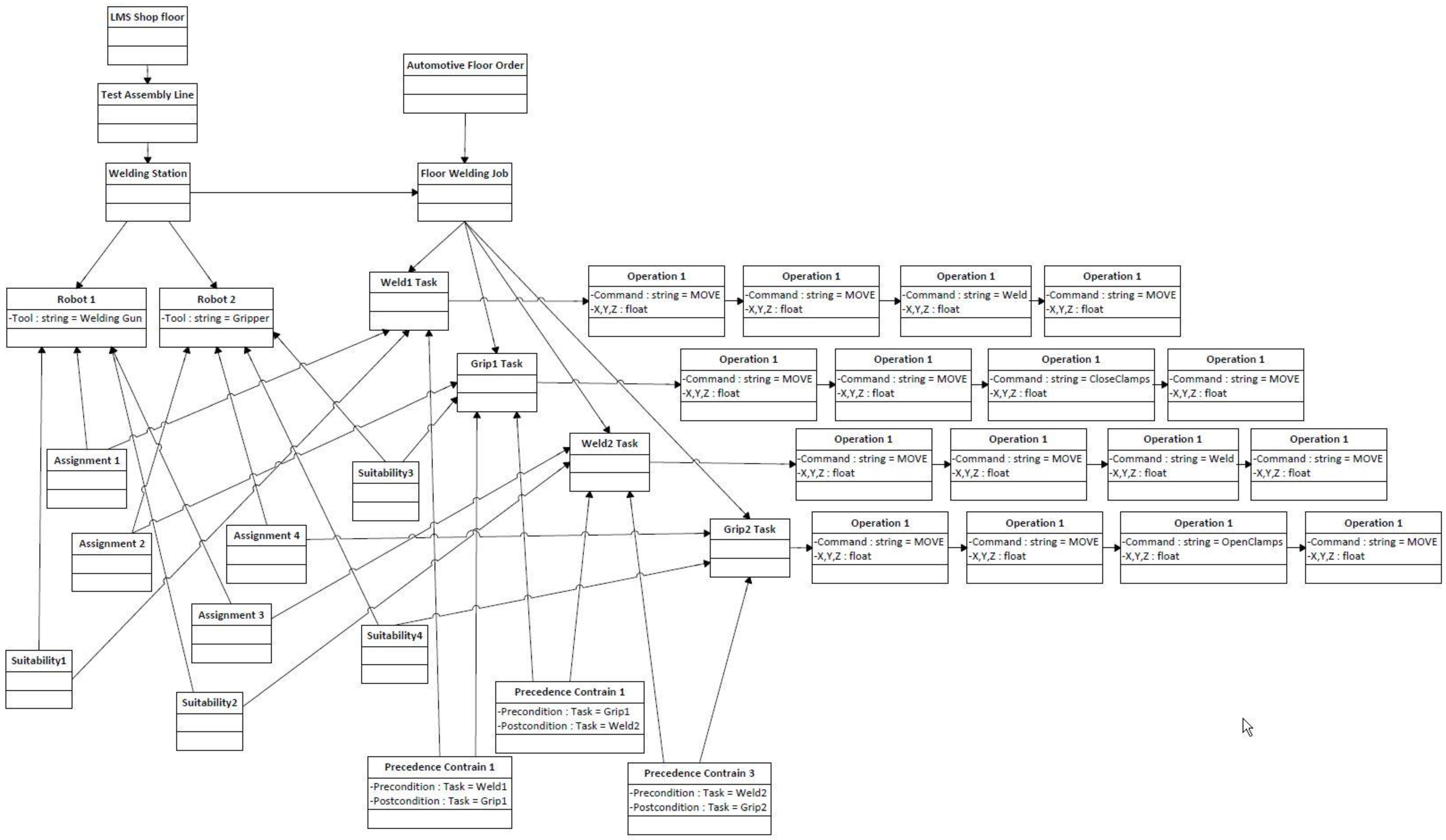
  • This scenario considers four tasks, namely, two welding and two handling operations. More specifically, tasks “Weld1-1” and “Weld1-2” represent the Geo and spot-welding tasks on the part. Similarly, tasks “Grip1-1” and “Grip1-2” represent the parts’ movement in space (for accessibility purposes) and the placing of the part on the table. The sequence constraints that have been introduced in the system involve:
    • Task “Weld1-1” having to be carried out before “Weld1-2”.
    • Task “Grip1-1” being a prerequisite for the task “Weld1-2”.
    • Task “Weld1-2” needing to precede the task “Grip1-2”.
For the control and orchestration of activities among the entities of the case study, the MAS approach was selected. The development of multi-agent frameworks is often based upon frameworks that implement common standards. An approach is to use a framework that adheres to the Foundation for Intelligent Physical Agents (FIPA) standard, namely, the Jade and JACK Intelligent Agents. In our case, the MAS implementation relies on the open-source Robot Operating System (ROS) platform [29], aimed at the development of robotics-related applications. In ROS, the framework agents may be represented as nodes, which are self-contained software modules that run independently and communicate with each other by passing messages over TCP/IP using the publish–subscribe pattern. In the context of this study, some initial experiments were executed to help the authors to identify the technology that would better suit their needs, especially with regards to the implementation environment. During these tests, the DPWS implementation provided by https://forge.soa4d.org/ was outperformed by the ROS service implementation, in terms of real-time performance. The average response time through the DPWS was approximately 50 ms, while with the ROS, the time dropped to a 5 ms average. Thus, the ROS Services mechanism was selected in support of SOA’s implementation along with MAS in this study.
In summary, the main reasons for selecting ROS in our implementation were:
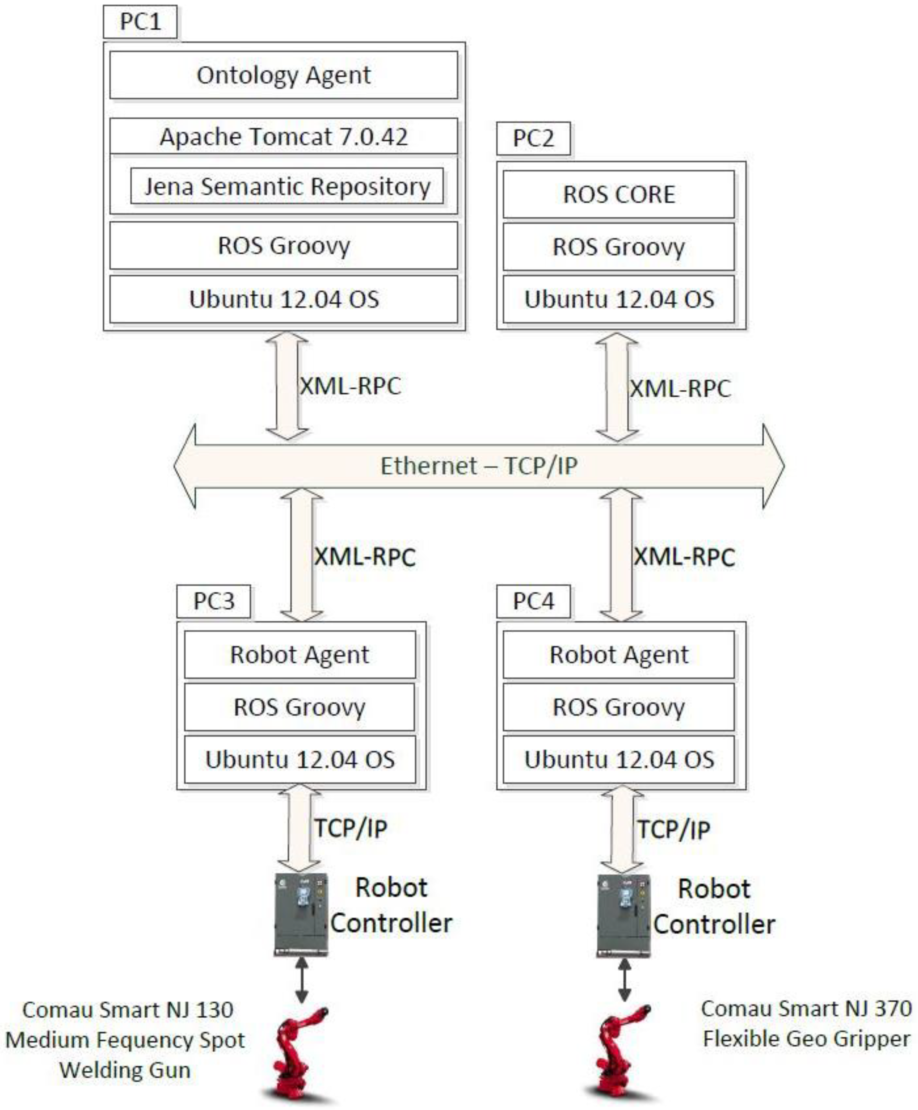
  • It is oriented towards real-time or soft real-time applications.
  • It provides mechanisms for the implementation of services and a service-oriented architecture.
  • It facilitates the requirements of the case study since it provides the necessary libraries and drivers for the selected hardware.
The knowledge management and exchange among agents in the multi-agent system is supported by an ontology that is implemented on top of the Apache Jena Semantic Repository [30], which serves the functionality of storing semantic data and performing semantic queries upon them.

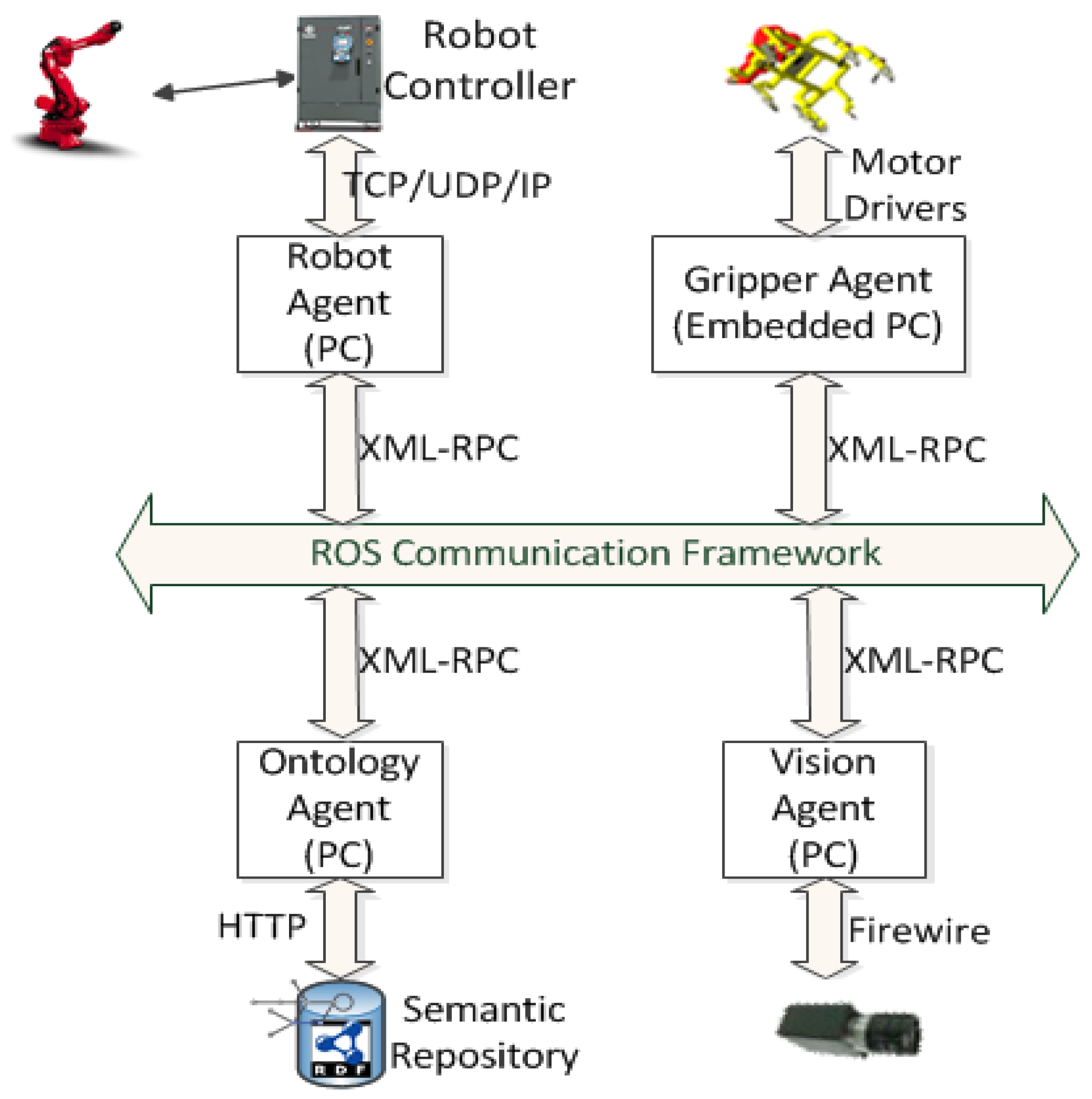
2. Approach for Multi-Agent Service-Oriented Integration

This research study aims to propose a multi-agent service-oriented framework, which is designed to support intelligent collaboration in a dynamic manufacturing environment. The following types of agents have been defined and implemented:
  • Robot.
  • Gripper.
  • Ontology.
  • Vision.
Their interactions and relationship diagrams are illustrated in Figure 2. Except for the gripper agent, which resides totally in an embedded device, the other types of agents reside in a local control PC. The agents exchange information with each other over the ROS Communication Framework, passing messages in the XML-RPC (eXtensible Markup Language-Remote Procedure Call) format. The agents may communicate with each other by using two different modes:
  • Asynchronously, by broadcasting XML-RPC messages to a topic. All agents that have subscribed to the topic receive certain data.
  • Synchronously, via the ROS Services mechanism. Each agent exposes its own services in certain names. Therefore, when another agent needs to communicate, it calls the right service and provides the appropriate input message.

2.1. Robot

The proposed robot agent is a smart software agent that is able to carry out the following tasks: (i) control the robot, (ii) communicate with other manufacturing agents and (iii) formulate alternative schedules depending on the status of the cell and the task’s execution progress. The architecture of the Robot agent is visualized in Figure 3, where the hardware and software modules of the robotic manufacturing unit are shown. Most modules are hosted by an external computer, whilst one module is hosted by the robot controller.
The robot agent has a two-layer architecture:
  • Low-level—written in robot programming language. The layer undertakes the real-time control functionalities to ensure adequate response times for the control system. It is also able to generate events aimed at the higher-level layer of the agent in order to create awareness of a new condition or state that needs to be acknowledged. The low-level part of the agent is hosted by the robot’s controller, which runs on a firmware that is able to execute low-level programs. This firmware communicates with the “Robot Coordinator” module through a typical TCP/IP interface. Sockets are defined over the TCP channel and are used in order to pass parameters to the low-level program that finally controls the robot’s movements.
  • High-level—written in a programming language such as C++ or Java. The high-level part controls the agent’s global behavior towards achieving its individual goal as well as coordinating its actions with other agents acting in the same system. The latter is the core of the agent, which is able to generate and implement alternative operation sequences and is hosted by a typical PC. The “Robot Coordinator” is a software module, whose role is to coordinate the tasks executed by the robotic unit and is connected to the low-level robot controller. It monitors the robotic unit and feeds it with information received from the rest of the platform (i.e., information about the welding spots of a subassembly). The “Data Access” module implements the communication mechanism. It is further responsible for composing valid messages from the “Robot Coordinator” data and feeding them to the platform upon request. It extracts the data contained in these messages and feeds them to the “Robot Coordinator”. Following the service-oriented paradigm, the “Data Access” module implements a set of services and advertises them to the platform. This set of services forms the “Robot Services”, and when any other resource or service consumes them, information can be retrieved from the “Robot Coordinator” about the robotic unit or feed information to it. For the implementation of these services, the ROS framework was used. Moreover, the robot agent contains the “Alternatives Generation and Evaluation” module, which can perform the scheduling and rescheduling of the shop floor’s pending tasks whenever requested.
The “Robot Services” interface consists of the following methods:
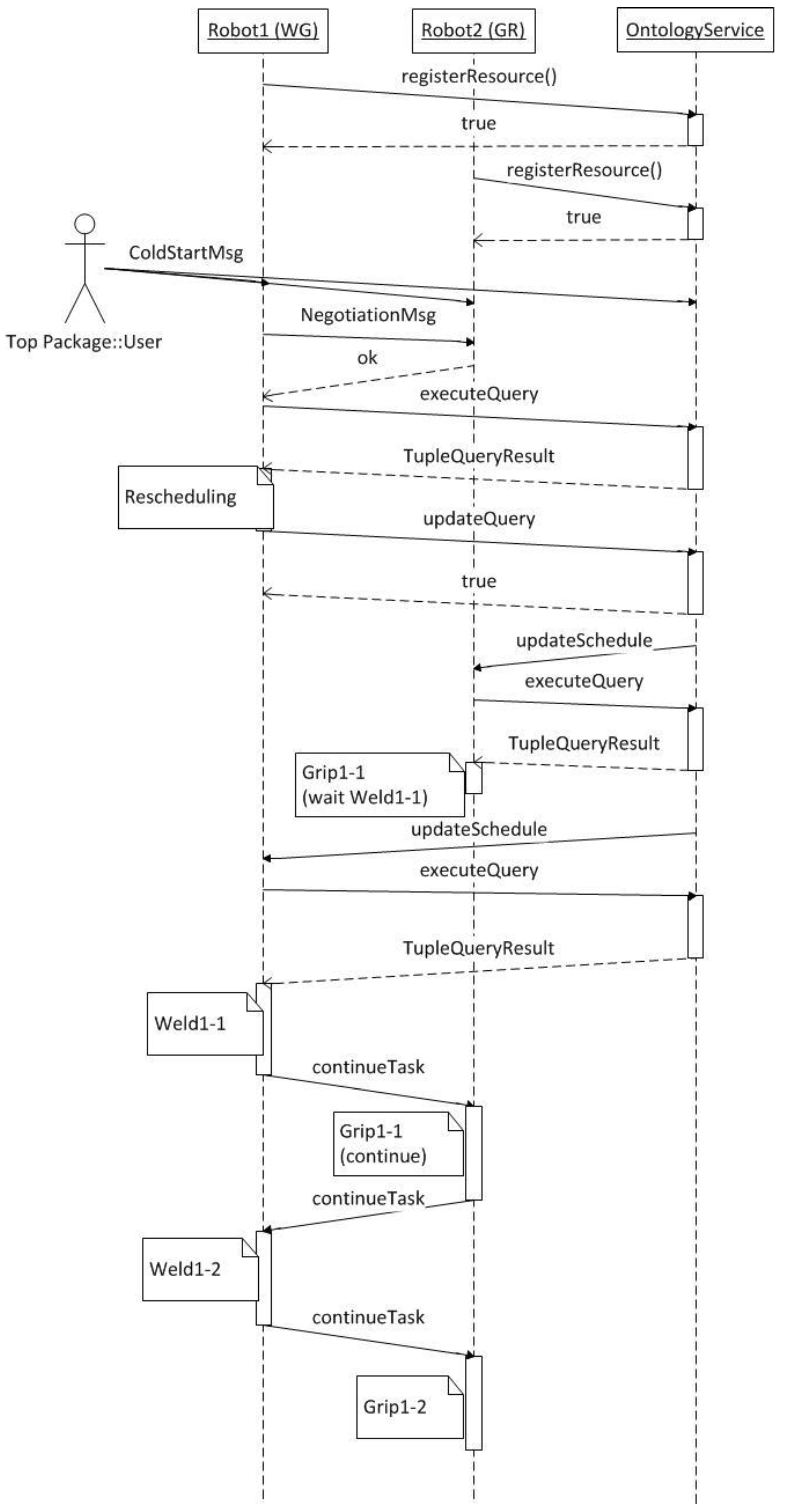
  • getPosition: When called, the robot service demands the robot arm coordinates from the Robot Controller by sending a message. Afterwards, the service returns these coordinates as a response to the client that asked for them.
  • continueTask: It is used to inform the robot resource that it should continue executing its next pending task. This method is useful when a manufacturing job comprises more than one task, which has pre- and post-conditions. If, for example, a manufacturing job is composed of two tasks, Task A and Task B—with Task B having, as a pre-condition, Task A—the following sequence of actions happens: the robot, which is assigned to perform Task B, suspends this task’s execution until Task A has been completed. When the resource assigned to perform Task A finishes it, it is informed by calling the proper “Ontology Service” of the resource assigned to Task B, and it calls upon this resource’s continueTask method. When this method has been called upon, the resource is informed of the pre-condition task’s completion and it resumes the execution of its assigned task.
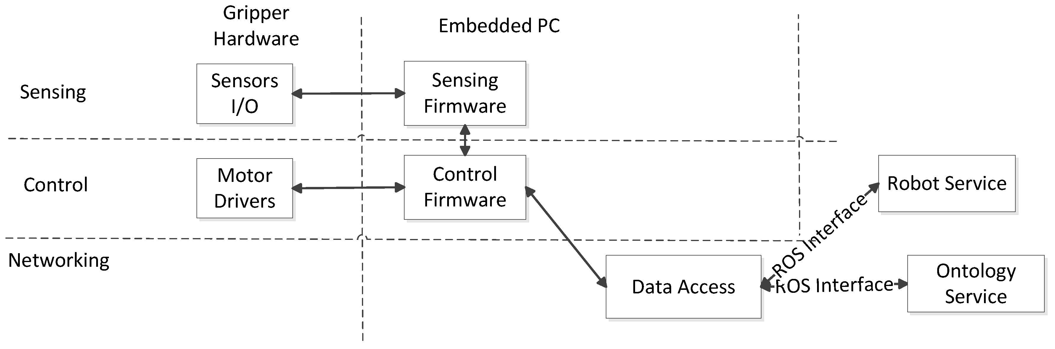
2.2. Gripper

The architecture of the Gripper agent is diagrammatically depicted in Figure 4. The gripper architecture includes the Gripper hardware unit, its firmware and the “Data Access” software module, which is hosted on an external computer connected with the gripper.
The Gripper hardware unit is controlled by the firmware running on the on-board controller (which is an embedded PC that is integrated within the mechanical and electrical parts of the gripper) of the hardware unit. This controller is an I/O module, supporting the ethernet/IP protocol. The I/O ports of this module control the clams of the Gripper and receive input and send input from the module’s ethernet/IP interface. Through this interface, the gripper firmware communicates with the “Data Access” software module. The “Data Access” module, similar to the robot architecture, forms the platform’s “Gripper Service”. It implements a set of services through which the other resources of the platform can both communicate and control the Gripper.
The “Gripper Service” interface comprises the following methods:
  • reconfigure: The Data Access module of the Gripper agent takes as input the ID of the target work piece. Then, it calls for the appropriate function of the Gripper Firmware Interface and passes from any current status to that with the arm configuration assigned to it. All arms and sliders are operated.
  • closeClamps: This service is called; the gripper is ready to grab the target work piece. The Data Access module calls the openClamps() function of the Gripper Firmware, and the gripper passes from any current status to that with all the relevant clamps closed.
  • openClamps: When this service is called, the gripper is ready to release the grabbed part. The openClamps() function of the Firmware Interface is responsible for opening the Gripper’s clamps.

2.3. Ontology

This agent consists of two modules, namely, the “Data Access” and the “Ontology Repository” modules. The “Ontology Repository” is a web server application with an embedded semantic “reasoner”. It serves the functionalities of storing semantic data and performing semantic queries upon them, using the embedded semantic reasoner to create the result sets. Moreover, it has the ability of using predefined semantic rules inside its reasoner. The “Ontology Repository” contains all the online data of the shop floor. These data are the online services and resources participating in the platform, the shop floor’s pending tasks, and the suitability of match between the resources and the pending tasks. For this reason, the shop-floor ontology, describing all the appropriate semantic data (see the details in Section 2.5), was developed. The Ontology Repository software module communicates with the rest of the platform, through the “Data Access” module, as is done in the robot architecture. In this case, the “Data Access2 module forms a set of services published to the platform as the “Ontology Services”. The use of these services enables the participating resources to store and retrieve data from the Ontology Server.
The “Ontology Services” interface comprises the following methods:
  • registerResource and registerService: The registerResource and registerService methods are called upon in order to inform the Ontology that a new resource or service has just been connected to the platform and should be registered. Every resource or service participating in the framework calls for the appropriate method to register itself to the platform. When registered, the Ontology knows that this resource or service is ready, online, to serve shop-floor tasks. Only registered services are taken into consideration when rescheduling is performed for the pending shop-floor tasks. Furthermore, the Ontology Service, by analyzing the broadcasted messages, remains aware of the unexpected platform events, and the resource or service break downs and updates the Ontology information.
  • executeQuery (string SPARQLQuery): It allows the platform resources to query the Ontology and retrieve information from it. For instance, the resource that performs rescheduling queries the Ontology about the existing shop-floor pending tasks, the online resources and their availabilities, and the suitability of “match” among the resources and the pending tasks.
  • updateQuery (string SPARQLQuery): It allows the platform resources and services to update the existing information lying in the Ontology or feed it with new ones. For example, when the robot agent finishes the rescheduling task, it calls for this method so as to supply the Ontology with the new assignments and update the already existing ones.
  • retrieveSchedule: This service is called for by every Robot’s agent, after a rescheduling task has taken place. After calling these services, the Data Access module of the Ontology makes a query at the Ontology Repository about the Robot’s tasks and operations. A list of the assigned tasks is returned as a response.
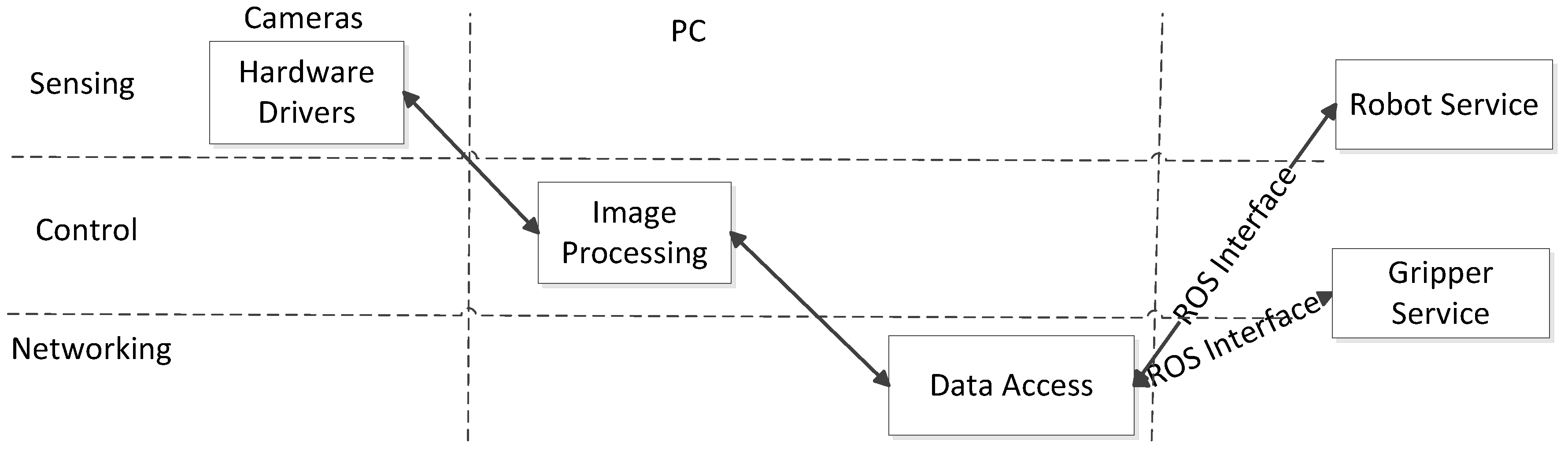
2.4. Vision

Similarly to the rest of the agents, the Vision agent communicates with the framework through its ROS interface, whose supporting services are exposed to the platform. This agent provides the whole framework with vision-sensing capabilities: it is able to perform image processing and provides recognition functionalities. In Figure 5, the Vision Service architecture is shown.
Apart from the two modules used for the communication, the Vision agent has the “Image Processing” module, which is connected to cameras. The “Image Processing” module accesses the platform requests through the “Data Access” module, performs the requested actions and returns the results to the platform through the “Data Access” module.
The “Vision Services” interface consists of the following methods:
  • performCalibration: The method performs the calculations for the identification of the relative position of the mobile unit base in relation to the docking station base. The method is required for the calculation of the mobile unit’s position with high precision.
  • identifyPart: The method identifies the automotive part types at each rack.
  • identifyPartLocation: The method identifies the parts’ positions and orientations inside the racks.

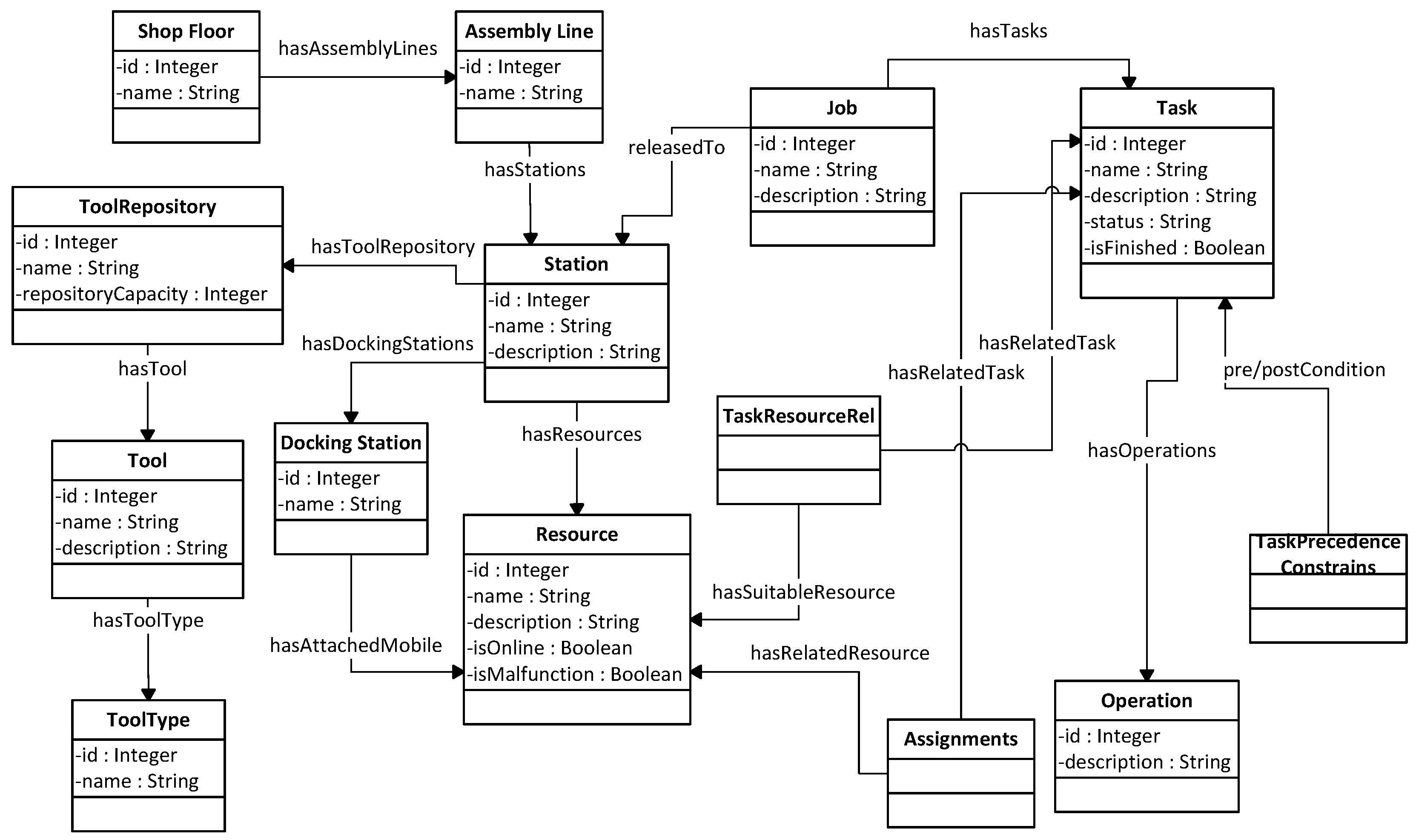
2.5. Ontology-Based Approach for Coordinating the Execution of Robotic Operations

In this chapter, there is a description of the approach used for coordinating the robotic operations. The approach involves two parts, namely:
  • An ontology knowledge base.
  • A decentralized negotiation and coordination mechanism.
To achieve an automatic coordination of robotic operations in real time, a model with adequate information about the agents responsible for task execution is required. The agent architecture discussed in this paper uses ontology and Semantic Web technologies for expressing the knowledge coming from the production environment. Hence, the agents rely on a resource, process and orders ontology that provides information on the manufacturing resources’ sequence of operations they control.
In Figure 6, there is a representation of the Ontology. It contains information about the shop floor, the existing assembly lines, the stations of each assembly line and the resources dedicated to each station. Furthermore, there is information about the orders arriving at the shop floor, dedicated to the production of a specific product. Each order is composed by specific jobs. Each job consists of several manufacturing tasks, and each task is described as a set of operations. Furthermore, there is information about the task execution sequence and the suitability of match among the pending tasks and the existing resources besides the assignments among the resources and the pending tasks available.
A schematic description of the data model using the Unified Modeling Language (UML), where all the data model classes are represented, can be seen above. This data model encapsulates all the information required by the agents to perform autonomous decision making. This information would have to represent the exact status of the shop floor not only in terms of physical objects and geometries but also in terms of operation execution status. The association or composition of the connected classes is also shown. More specifically:
  • “hasAssemblyLine” declares that an assembly line belongs to a certain shop floor.
  • “hasStation” connects an assembly line with all the working stations located in it.
  • “hasResource” connects a working station with all the robots located in it.
  • “hasToolRepository” is used to associate each work station with its tool repository.
  • “hasDockingStation” associates each work station with its docking station.
  • “hasAttachedMobileResource” connects the docking station with the mobile resource docked on it.
  • “hasTool” connects the resources with their attached tools.
  • “hasToolType” declares the type of each tool by connecting it with the specified tool type.
  • “releasedToStation” declares that a job is released and will be executed within a certain station.
  • “hasTasks” connects the job with its tasks.
  • “hasOperations” connects a task with its operations.
  • “hasPreCondition” declares that a task must be completed before a certain task begins.
  • “hasPostCondition” declares that a task must start after a certain task is completed.
  • “hasRelatedTask” is a property of the TaskResourceRel class. It is used together with the “hasSuitableResource” property to denote that a certain task can be executed by a certain resource.
  • “hasRelatedResource” is a property of the Assignment class. The Assignment class is connected with a resource using this property and with a task using the “hasRelatedTask” property.
The representation of all such characteristics enables their automated integration in the decision-making process, through the Ontology technologies. To define the Ontology model, a systematic representation representing the interplay between the production processes and resources needs to be formulated.
Regarding the hierarchical model of the assembly system, the “Shop Floor” represents the complete production facility and encompasses a number of “Assembly Lines”. Each “Assembly Line” incorporates several “Stations”, which, in turn, involve one or more “Resources”. “Assembly Lines” mainly refer to dedicated parts of the facility where a specific subassembly or component of the product is produced. “Stations” are used to denote smaller cells or groups of resources that are included in the line and are responsible for a subset of the manufacturing operations. According to this work’s approach a “Task” is assigned to a station and then dispatched to a resource inside this station. “Resource” is used to describe a specific machine or equipment executing a task from start to end.
In analogy to the facilities hierarchy, the workload also follows a similar breakdown. The higher level includes the “Orders”, which, in turn, consist of “Jobs” that are made up of several “Tasks”. The “Tasks” of a specific “Job” must be carried out by the “Station” where the “Job” is “releasedTo”. Therefore, “Tasks” can be carried out by one or multiple “Resources”, and the mapping of tasks to Resources is decided by a scheduling algorithm such as a dispatching rule.
The Ontology presented above is utilized by a decentralized coordination and negotiation mechanism, being responsible for the handling of events (for example, the introduction of new orders or the breakdown of a resource) arising at the shop floor. The decentralized mechanism is based on a negotiation procedure used for the selection of the agent that performs rescheduling in order for the resultant event to be handled. In many proposed dynamic-manufacturing scheduling systems, there is usually a preselected node that performs the scheduling calculations [17]. In this study, a new schema is proposed in which every resource agent may undertake the role of a coordinator by providing the sequence of operations. The negotiation and synchronization are performed bilaterally between the resource agents and the ontology agent. A similar problem has already been faced in peer-to-peer networks, known as the super-node selection problem. In such cases, several negotiation mechanisms, addressing this problem, have been developed [31]. In the proposed system, a negotiation mechanism has been developed, oriented towards a fast response time and a low data exchange in order for the overloading of the network infrastructure to be avoided. When the Robot agents need to negotiate with each other, they calculate an indicator, based on the processing load they have by that time, and broadcast a message containing this number to a common topic. Then, they await the publishing of all the negotiation messages in the same topic, containing the numbers of the other agents over a specific time. When the negotiation time is up, each agent compares the numbers received by all the other agents with its own transmitted number (illustrated as the “Calculating” process in Figure 7), and the agent with the lowest number, and thus with the lowest processing load, broadcasts a negotiation finish message and is then responsible for performing the rescheduling process. Then, the agent triggers an external scheduler module, which takes the data from the ontology repository, performs the scheduling, writes the assignments in the ontology and sends a message informing all the agents that the scheduling is over. The scheduling method is described in detail in [32,33]. The negotiation process is graphically presented in Figure 7. For the implementation of this mechanism, the ROS topic communication technology has been utilized. A specific topic has been created, and each robot agent is configured to register itself to this topic when connected to the network.
When the rescheduling calculations have been performed, the Ontology agent is notified, and the new task assignments are updated into the ontology. Then, the Robot agent, having performed the calculations, informs the rest of the agents about the new assignments. This is achieved by sending a ROS message “reached” to the common ROS topic to which all the robot agents are subscribed. Next, all the robot agents retrieve the new task assignments along with the task operations by calling the retrieveSchedule service of the Ontology agent and continue controlling the manufacturing resources in order to perform those tasks.

3. Case Study Implementation and Discussion of Results

This section discusses the realization, testing and evaluation of the proposed solution for the case study presented in Section 2.2. The system was tested in a scenario that involves the coordination (scheduling) of tasks to be performed by the production resources.
At the beginning of the cell operation, the Robot agents negotiate in order to decide which of the two will undertake the scheduling of the tasks, i.e., the assignment of the tasks to the two robots. After the decision has been made, the selected robot agent considers the resource–task suitability and the sequence constraints (e.g., task “Weld1-1” has to be carried out before “Weld1-2”) and generates the schedule that indicates which resource is to be used (i.e., which tasks the robot and gripper execute). In the next step, the schedule derived for each robot is stored in the ontology so that it is accessible by the robot service. Each agent retrieves the respective schedule from the ontology and then controls the robot accordingly. The task to be executed defines the transmitted data, which include the coordinates of the points to be reached by the robot, the welding parameters, the motion type (joint or linear) and other information. Following this, upon the completion of each task, the robot agent notifies the ontology in order for the other robot that is waiting to start executing the tasks that have been dispatched to it. Once all the tasks are finished, the handling robot positions the final assembly on the table and retracts so that the operators may move the part from its working area.

3.1. Implementation Details

The approach proposed in this work was applied in a test case in a laboratory environment that involved the automated configuration and real-time coordination of two industrial robots for the welding of car floor parts. The scenario described in the previous paragraph was met using the approach presented in this paper. Figure 8 presents the hardware and software architecture for the implemented case study. In total, four PCs were configured, three of which were host agents (two robots and one ontology), while the fourth one was configured to host the ROS infrastructure. The ontology agent was configured on top of a Jena. In the original configuration of the cell, the cooperative behavior of robots was achieved through a master/slave coupling under a DeviceNet network. For the purposes of this research, the robot cell infrastructure was modified to accommodate the agent-based communication between the robots. More specifically, two desktop PCs running ROS on top of Linux Ubuntu v.12.04 were configured and connected to the robot controllers through ethernet connections. Each robot was connected to its own Comau C4G open controller. The Comau PDL2 robot programming language was used in order to program the Comau C4G controller, and thus, the low-level layer of the robot agent was written in PDL2.
In Figure 9, the individual entities of the ontology model are presented. This Ontology instantiation constitutes the description of the laboratory assembly equipment with one welding station. In the welding station, two manufacturing resources exist, one robot with a gripper attached to it and a second one with a welding gun attached to it. For this scenario, we assume that a new order that is an automotive floor arrives, and this order comprises a floor-welding job with four tasks. The ontology instantiation of each task has its precedence constraints and the operations that describe it. Furthermore, within the instantiation of the Ontology, there is information about the assignments and the suitability among the existing resources and the tasks.
In Figure 10, the sequence diagram of the use-case scenario is presented. For this scenario, we assume that the robot agents are now turned on and an automotive floor order has just arrived with four pending tasks, as they are also described in the Ontology instantiation. We can further assume that it has been defined which task will be performed by a specific resource, but no scheduling calculations have been performed and no assignments among the arrived tasks and the resources exist. The use-case scenario starts with the registration of the robot agents to the platform. Each agent registers itself to the platform, consuming the registering function of the Ontology Service. In that case, the Robot agents utilize the negotiation and coordination mechanism to perform a negotiation and decide which one will make the scheduling calculations. When the negotiation has finished, the selected agent retrieves from the Ontology Service all the appropriate information required for the task scheduling by the “executeQuery” function. When the assignments of the pending tasks have been made, the agent stores these data in the Ontology Service using the “updateQuery” function. After the scheduling process has finished, the registered robot agents are informed by the Ontology Service that there are new pending tasks assigned to them by means of publishing a message at the common ROS topic, to which everyone is subscribed. Each agent then, by calling the “retrieveSchedule” service, retrieves its pending tasks and starts executing them. The first robot agent starts the execution of the “Weld1-1” Task by processing, one by one, the task’s operations while sending the appropriate commands to the manufacturing resource. The second robot agent starts executing the “Grip1-1” task. The first operation of this task is to wait for the pre-condition tasks to be executed, in this case, the task “Weld1-1”. In this way, the agent enters a “hold state”, waiting for the first robot agent to complete its task and inform it. When the “Weld1-1” task has finished, the first robot agent, utilizing the Ontology Service, retrieves all the post-conditions of these tasks and informs the agents assigned to them. In this case, the first robot agent informs the second robot agent, by calling the “continueTask” function, that the “Weld1-1” task has been performed. The same procedure is followed for the execution of all the pending tasks, namely, the “Weld1-2” and the “Grip1-2” tasks.

3.2. Discussion and Comparison with Other Approaches

At this point, the most common way of synchronizing various tasks, among many robots, is with the use of both signals and a PLC before and after a certain task execution.
Every time that a job to be performed by two or more robots has to be executed, the signals need to be sent and received by the robots in order to satisfy all the precedence constraints between the various tasks. Firstly, the controller of every robot has to be connected to the master PLC unit that controls the I/O signals of every robot. Depending on the PLC unit, the ethernet, DeviceNet or RS-232 connection protocols are supported. Afterwards, the robot controllers and the PLC unit need to be turned on and start writing the robot’s programs for each task. The welding robot is ordered to wait until the first gripping task has finished. Consequently, a command is included at the start of the welding robot program to wait until a certain memory slot of the PLC becomes true. The gripping robot provides information upon finishing its first task. Therefore, after this task has been executed, it sends the signal in order for the welding robot to be able to continue.
This approach, which is most commonly used in robot synchronization, requires a lot of time for the setup, especially if there are more than two robots with several precedence constraints. Furthermore, the programmer should know which memory slots of the PLC are available, in order to use them for synchronization. The risk of updating a false memory slot and signaling the wrong robot to continue is possible. The only way of eliminating this risk is the use of virtual commissioning technologies in order for a simulation of the sequencing to be performed first, on the PC, before its application to the real robots [34]. Figure 11 provides a high-level overview of the PLC approach.
On the contrary, the use of the agent-based system previously described, the time for embedding the manufacturing resources into the system and the effort for programming them for achieving synchronization are reduced.
The setup phase only requires the turning on of the robot controllers and the PCs that the robot agent software is running on. No connection to master the PLC is required. For enabling communication, the robot agent PCs must be connected to the same network.
During the programming phase, the only required action is that the operations are added to the Ontology Repository and the pre- and post-conditions for each task are set up. Then, during the execution phase, new operations for waiting and sending notifications to continue are generated according to the precedence constraints that the user has defined. After that, the robots can start their negotiation in order to enter the execution phase.
The duration of the setup and the programming phases of the above scenario for both approaches is discussed. Four major tasks are identified for measuring the time needed for each approach: network configuration, robot programming, task-sequencing configuration and the integration of new resources. The performance for the hierarchical approach is based on an expert’s estimation, while the performance of the proposed system was estimated upon testing the system on the different cases.
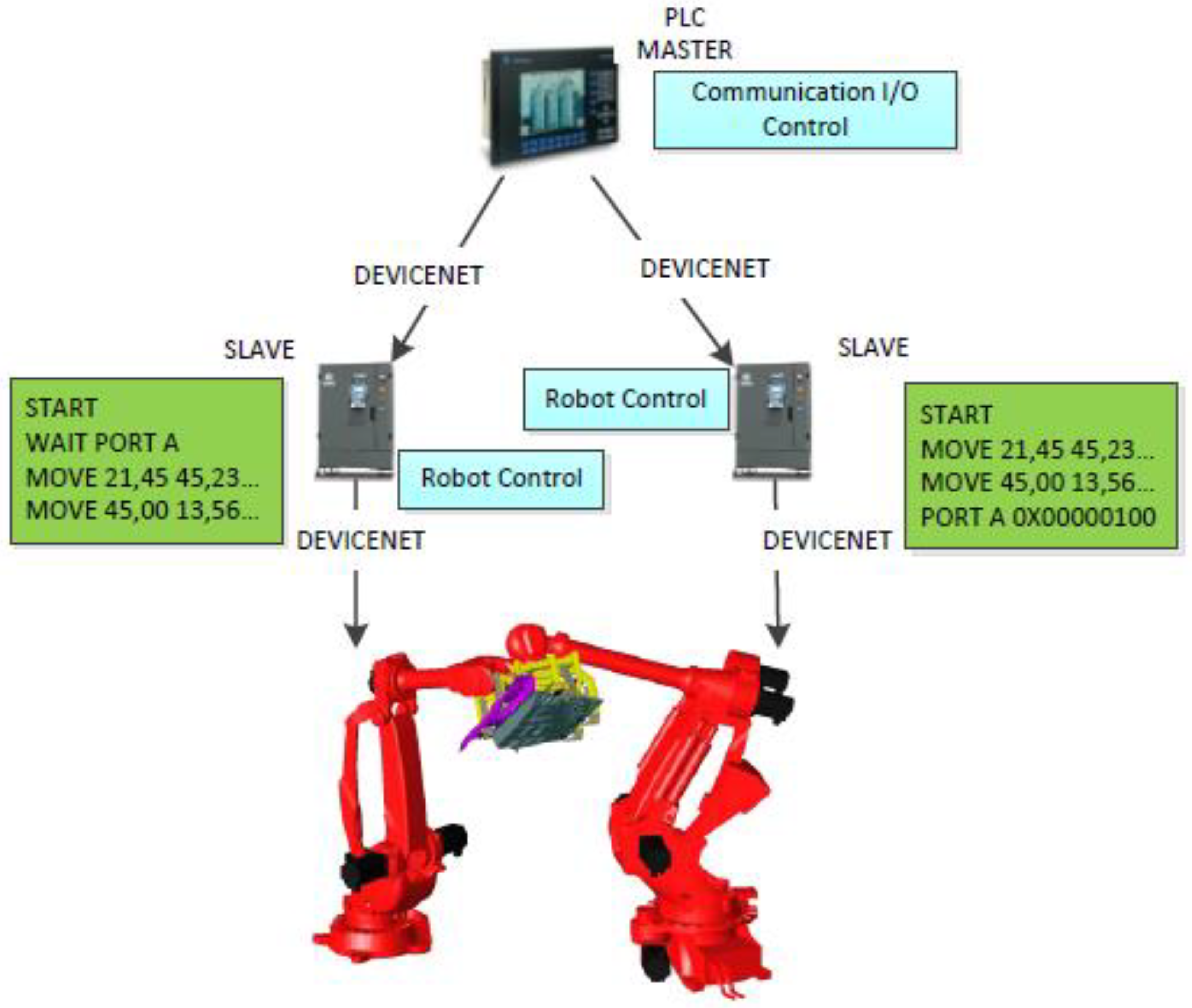
  • Network configuration: With the proposed approach, the network configuration time is significantly reduced. Using the PLC approach, approximately 8 h is needed to configure the fieldbus network including the gripper I/O configuration and the mapping of the robot I/Os to those configured at the gripper side. On the other hand, with a resource that can support the TCP/IP protocol, the only requirement is to connect all the resources at the same network (0.5–1 h).
  • Robot program: There is not any foreseen effect on the time needed for the robot programming. The writing of the robot program takes approximately the same time in both approaches.
  • Task sequencing configuration: If no standard is used for PLC programming—as is the case in several industrial sites—the development of interlocking PLC commands for task sequencing takes 5–8 h. Using the proposed approach, it is only necessary to configure the precedence constraints of each couple of tasks at the ontology, which may take approximately 1–2 h if a generic purpose Ontology editing tool (e.g., Protégé) is used or even less (approximately 10–20 min) if a specific end-user application is available.
  • Integration of new resources: Using the traditional hierarchical approach, in case the new resource has the same configuration (same vendor, same gripper and same IO configuration) as the already installed resource, it is only necessary to copy the robot program to the controller (0.5 h). However, if the robot is not configured properly (e.g., has a different vendor), we also need to program the PLC signaling (approximately 3 h). On the other hand, when using the agent-based system developed in this paper, we only need to add the new robot in the ontology and configure the task-resource suitability (10–20 min using the Protégé Ontology editor).
In summary, the application of this approach to a simple scenario that includes the cooperation of two robots can save a significant amount of setup and programming time. A job that previously could take up to two working days to be set up now requires a couple of hours. In more complex jobs, where more tasks need to be synchronized, the time saving—and, subsequently, the economic profit—can be even bigger. Moreover, the programmer does not need to keep in mind all the memory slots that are being altered at the PLC. Thus, the risks of sending the wrong signals to the wrong robots are reduced.

4. Conclusions and Future Work

The automated configuration and the coordination of production equipment are considered important capability factors for manufacturing systems in enhancing their overall performance. Currently, configuration and coordination are usually performed with a centralized decision-making approach with fixed and rigid control logic that reduces responsiveness, flexibility and re-configurability. This work proposes an approach that combines the benefits of three key technologies, namely, agent-based manufacturing, service-oriented architecture, and ontology. In order for the aforementioned capabilities to be enabled, the production equipment is introduced and accessed by the proposed system as a software agent that registers itself through the ontology service. Based on the ontological representation of the production equipment and its relations, the system automatically determines and initiates the configuration and coordination process. SOA is used in order for the resource agents to communicate with each other and derive alternative schedules for the accommodation of disturbances.
The system was developed and applied in an industrial case study of the robotics-based welding of automotive floor parts. The application in the case study showed that the proposed system can save setup and programming time by shifting the effort from low-level rigid PLC programming to the configuration of flexible agents as well as the ontology that supports their coordination. The time required to configure the network among the production resources and the integration of new resources can be reduced when assisted by the ontology-based registration of the equipment’s network settings. Effort spent on task-sequencing configuration is reduced, as the task precedence diagram can be represented via high-level ontological data available to the resource agents.
Future work will need to focus on the development of a diagnostic system that, through the observation of shop-floor events, computes the set of faults that may occur or a set of fault states that the system may reach. In this way, high-level semantic information about the actual state can be sent to the decision-making modules of the control architecture, thus enabling the deployment of proactive fault-handling strategies. Furthermore, towards the direction of error and exception handling, the use of mobile robots could be useful. In case something unexpected takes place while a robot is executing a certain task, a mobile robot could then approach it and carry on its task.

Author Contributions

Conceptualization, S.M. and G.M.; methodology, S.M. and K.A.; software, K.A. and A.S.; validation, G.M. and A.S.; writing, S.M., K.A., G.M. and A.S.; writing—original draft preparation, S.M., K.A.; writing—review and editing, S.M., K.A., G.M.; visualization, G.M., K.A., A.S. All authors have read and agreed to the published version of the manuscript.

Funding

This research has been partially supported by the research project “TRINITY—Digital Technologies, Advanced Robotics and increased Cyber-security for Agile Production in Future European Manufacturing Ecosystems” funded by the European Commission.

Conflicts of Interest

The authors declare no conflict of interest.

References

  1. Chryssolouris, G. Manufacturing Systems: Theory and Practice, 2nd ed.; Springer: New York, NY, USA, 2006. [Google Scholar]
  2. Brennan, W.R.; Vrba, P.; Tichy, P.; Zoitl, A.; Sunder, C.; Strasser, T.; Marik, V. Developments in dynamic and intelligent reconfiguration of industrial automation. Comput. Ind. 2008, 59, 533–547. [Google Scholar] [CrossRef]
  3. Leitao, P. Agent-based distributed manufacturing control: A state-of-the-art survey. Eng. Appl. Artif. Intell. 2009, 22, 979–991. [Google Scholar] [CrossRef]
  4. Scholz-Reiter, B.; Freitag, M. Autonomous processes in assembly systems. CIRP Ann. 2007, 56, 712–729. [Google Scholar] [CrossRef] [Green Version]
  5. Monostori, L.; Váncza, J.; Kumara, S.R.T. Agent-based systems for manufacturing. CIRP Ann. 2006, 55, 697–720. [Google Scholar] [CrossRef] [Green Version]
  6. Mourtzis, D.; Papakostas, N.; Mavrikios, D.; Makris, S.; Alexopoulos, K. The role of simulation in digital manufacturing—Applications and outlook. Int. J. Comput. Integr. Manuf. 2015, 28, 3–24. [Google Scholar] [CrossRef]
  7. Monostori, L.; Kádár, B.; Pfeiffer, A.; Karnok, D. Solution approaches to real-time control of customized mass production. Ann. CIRP 2007, 56, 431–434. [Google Scholar] [CrossRef]
  8. Guo, Q.; Zhang, M. An agent-oriented approach to resolve scheduling optimization in intelligent manufacturing. Robot. Comput. Integr. Manuf. 2010, 26, 39–45. [Google Scholar] [CrossRef]
  9. Mezgebe, T.T.; Bril El Haouzi, H.; Demesure, G.; Pannequin, R.; Thomas, A. Multi-agent systems negotiation to deal with dynamic scheduling in disturbed industrial context. J. Intell. Manuf. 2020, 31, 1367–1382. [Google Scholar] [CrossRef]
  10. Mishra, N.; Singh, A.; Kumari, S.; Govindan, K.; Ali, S.I. Cloud-based multi-agent architecture for effective planning and scheduling of distributed manufacturing. Int. J. Prod. Res. 2016, 54, 7115–7128. [Google Scholar] [CrossRef]
  11. Papakostas, N.; Mourtzis, D.; Makris, S.; Michalos, G.; Chryssolouris, G. An agent-based methodology for manufacturing decision making: A textile case study. Int. J. Comput. Integr. Manuf. 2012, 25, 509–526. [Google Scholar] [CrossRef]
  12. Rocha, A.; Barata, D.; di Orio, G.; Santos, T.; Barata, J. PRIME as a Generic Agent Based Framework to Support Pluggability and Reconfigurability Using Different Technologies. In Proceedings of the 6th IFIP WG 5.5/SOCOLNET Doctoral Conference on Computing, Electrical and Industrial Systems, DoCEIS 2015, Costa de Caparica, Portugal, 13–15 April 2015. [Google Scholar] [CrossRef]
  13. Cruz Salazar, L.A.; Ryashentseva, D.; Lüder, A.; Vogel-Heuser, B. Cyber-physical production systems architecture based on multi-agent’s design pattern—Comparison of selected approaches mapping four agent patterns. Int. J. Adv. Manuf. Technol. 2019, 105, 4005–4034. [Google Scholar] [CrossRef] [Green Version]
  14. Shen, W.; Hao, Q.; Wang, S.; Li, Y.; Ghenniwa, H. An agent-based service-oriented integration architecture for collaborative intelligent manufacturing. Robot. Comput.-Integr. Manuf. 2007, 23, 315–325. [Google Scholar] [CrossRef]
  15. Zhang, Y.; Huang, G.Q.; Qu, T.; Ho, O.; Sun, S. Agent-based smart objects management system for real-time ubiquitous manufacturing. Robot. Comput.-Integr. Manuf. 2011, 27, 538–549. [Google Scholar] [CrossRef]
  16. Candido, G.; Jammes, F.; de Oliveira, J.B.; Colombo, A.W. SOA at device level in the industrial domain: Assessment of OPC UA and DPWS specifications. In Proceedings of the 8th IEEE International Conference on Industrial Informatics (INDIN), Osaka, Japan, 13–16 July 2010; pp. 598–603. [Google Scholar] [CrossRef]
  17. Wang, C.; Shen, W.; Ghenniwa, H. An adaptive negotiation framework for agent based dynamic manufacturing scheduling, IEEE International Conference on Systems. Man Cybern. 2003, 2, 1211–1216. [Google Scholar]
  18. Vrba, P.; Radakovič, M.; Obitko, M.; Mařík, V. Semantic technologies: Latest advances in agent-based manufacturing control systems. Int. J. Prod. Res. 2011, 49, 1483–1496. [Google Scholar] [CrossRef]
  19. Secchi, C.; Bonfe, M.; Fantuzzi, C. On the Use of UML for Modeling Mechatronic Systems. IEEE Trans. Autom. Sci. Eng. 2007, 4, 105–113. [Google Scholar] [CrossRef]
  20. Ocker, F.; Kovalenko, I.; Barton, K.; Tilbury, D.; Vogel-Heuser, B. A Framework for Automatic Initialization of Multi-Agent Production Systems Using Semantic Web Technologies. IEEE Robot. Autom. Lett. 2019, 4, 4330–4337. [Google Scholar] [CrossRef]
  21. Ciortea, A.; Mayer, S.; Michahelles, F. Repurposing manufacturing lines on the fly with multi-agent systems for the Web of Things. In Proceedings of the 17th International Conference on Autonomous Agents and MultiAgent Systems (AAMAS), Stockholm, Sweden, 10–15 July 2018; pp. 813–822. [Google Scholar]
  22. Reinhart, G.; Krug, S. Automatic Configuration (Plug & Produce) of Robot Systems—Data-Interpretation and Exchange. In Enabling Manufacturing Competitiveness and Economic Sustainability; Springer: Berlin/Heidelberg, Germany, 2012; pp. 147–152. [Google Scholar]
  23. Efthymiou, K.; Sipsas, K.; Melekos, D.; Georgoulias, K.; Chryssolouris, G. A Manufacturing Ontology Following Performance Indicators Approach. In Proceedings of the 7th International Conference on Digital Enterprise Technology, Athens, Greece, 28–30 September 2011; pp. 586–595. [Google Scholar]
  24. Efthymiou, K.; Alexopoulos, K.; Sipsas, P.; Mourtzis, D.; Chryssolouris, G. Knowledge management framework supporting manufacturing system design. In Proceedings of the 7th International Conference on Digital Enterprise Technology, Athens, Greece, 28–30 September 2011; pp. 577–585. [Google Scholar]
  25. Lepuschitz, W.; Zoitl, A.; Merdan, M. Ontology-Driven Automated Software Configuration for Manufacturing System Components. In Proceedings of the IEEE International Conference on Systems, Man, and Cybernetics (SMC), Anchorage, AK, USA, 9–12 October 2011. [Google Scholar]
  26. Lohse, N.; Ratchev, S.; Barata, J. Evolvable Assembly Systems—On the role of design frameworks and supporting ontologies. IEEE Int. Symp. Ind. Electron. 2006. [Google Scholar] [CrossRef]
  27. Alsafi, Y.; Vyatkin, V. Ontology-based reconfiguration agent for intelligent mechatronic systems in flexible manufacturing. Robot. Comput.-Integr. Manuf. 2010, 26, 381–391. [Google Scholar] [CrossRef]
  28. Orio, G.; Rocha, A.; Ribeiro, L.; Barata, J. The PRIME Semantic Language: Plug and Produce in Standardbased Manufacturing Production Systems. In Proceedings of the Flexible Automation and Intelligent Manufacturing, FAIM 2015, Wolverhampton, UK, 23–26 June 2015. [Google Scholar]
  29. Quigley, M.; Gerkey, B.; Conley, K.; Faust, J.; Foote, T.; Leibs, J.; Berger, E.; Wheeler, R.; Ng, A. ROS: An open-source Robot Operating System. In Proceedings of the Open-Source Software Workshop (ICRA), Kobe, Japan, 12–13 May and 17 May 2009. [Google Scholar]
  30. Jena Framework. Available online: http://jena.apache.org/ (accessed on 9 September 2020).
  31. Lo, V.; Zhou, D.; Liu, Y.; GauthierDickey, C.; Li, J. Scalable Supernode Selection in Peer-to-Peer Overlay Networks. In Proceedings of the Second International Workshop on Hot Topics in Peer-to-Peer Systems, San Diego, CA, USA, 21 July 2005; pp. 18–27. [Google Scholar]
  32. Michalos, G.; Sipsas, P.; Makris, S.; Chryssolouris, G. Decision making logic for flexible assembly lines reconfiguration. Robot. Comput.-Integr. Manuf. 2016, 37, 233–250. [Google Scholar] [CrossRef]
  33. Kousi, N.; Dimosthenopoulos, D.; Matthaiakis, A.-S.; Michalos, G.; Makris, S. AI based combined scheduling and motion planning in flexible robotic assembly lines. Procedia CIRP 2019, 86, 74–79. [Google Scholar] [CrossRef]
  34. Makris, S.; Michalos, G.; Chryssolouris, G. Virtual Commissioning of an Assembly Cell with Cooperating Robots. Adv. Decis. Sci. 2012, 2012, 428060. [Google Scholar] [CrossRef] [Green Version]
Figure 1. Robotic assembly cell (a) photo and (b) top-view layout.
Jmmp 04 00095 g001
Figure 2. Agent relationship and interaction diagram for the multi-agent framework. User Datagram Protocol (UDP), Transmission Control Protocol (TCP), Internet Protocol (IP), eXtensible Markup Remote Procedure Call (XML-RPC), Hypertext Transfer Protocol (HTTP), Robot Operating Systems (ROS).
Jmmp 04 00095 g002
Figure 3. Robot agent architecture.
Jmmp 04 00095 g003
Figure 4. Gripper agent architecture.
Jmmp 04 00095 g004
Figure 5. Vision agent architecture.
Jmmp 04 00095 g005
Figure 6. Ontology.
Figure 6. Ontology.
Jmmp 04 00095 g006
Figure 7. Negotiation mechanism.
Jmmp 04 00095 g007
Figure 8. Hardware and software architecture of the laboratory implementation.
Jmmp 04 00095 g008
Figure 9. Use-case instantiation of the ontology model.
Jmmp 04 00095 g009
Figure 10. Scenario sequence diagram.
Jmmp 04 00095 g010
Figure 11. Programmable Logic Controller (PLC) approach for robot synchronization.
Jmmp 04 00095 g011

