Communication

Hemming with Pre-Bent Inner Sheet for Joining Ultra-High Strength Steel Sheets of Automobile Parts

Faculty of Engineering, Toyohashi University of Technology, 1-1 Tempaku-cho, Toyohashi, Aichi 441-8580, Japan
*
Author to whom correspondence should be addressed.
J. Manuf. Mater. Process. 2020, 4(3), 77; https://doi.org/10.3390/jmmp4030077
Submission received: 29 June 2020 / Revised: 21 July 2020 / Accepted: 23 July 2020 / Published: 25 July 2020

Abstract

:
In order to join two ultra-high strength steel sheets with low ductility for automobile parts, a joining process by hemming with a pre-bent inner sheet was developed. In this joining, the pre-bent inner sheet instead of the conventional flat inner sheet was used to relax the deformation concentration of the outer sheet. Although 780 MPa steel sheets were joined without the pre-bent inner sheet, a fracture in the outer sheet occurred in joining the 980 MPa sheets due to the low ductility of the sheets. The 980 MPa and 1180 MPa sheets were successfully joined by hemming with the pre-bent inner sheet. In this process, the deformation of the upper sheet was relaxed by contacting with the inner sheet, and then the strain on the outer surface reduced. Although softening around a weld nugget occurred by heating in the conventional welded joint, work-hardening occurred in the hemmed joint. The joint strength was investigated and then the peel strength of the hemmed sheets was about a half of the welded one. It was found that the hemming process with the pre-bent inner sheet was effective for joining ultra-high strength steel sheets with low ductility.

1. Introduction

The light weight and the collision safety of automobiles are important. For the reduction in weight and the increase in collision strength of automobile body parts, the application of high specific material sheets, such aluminum alloy sheets and ultra-high and high-strength steel sheets is effective [1]. These parts are usually formed by multi-stage stamping, and then the stamped parts are joined to an assembled part. In lap joints for joining steel sheets, resistance spot welding is usually used because of the high productivity and low joining cost. In this welding, cylindrical electrodes touch a lap joint of two sheets, and resistance heating produces a spot weld. Although the galvanized high strength steel sheets with zinc alloy coating layers are joined by this welding, dressing the electrodes to remove the adhered zinc alloy is frequently performed—i.e., the tooling cost is increased [2]. In addition, the liquid metal embrittlement that causes the reduction in elongation and failure and early fracture of the galvanized steel sheets is prevented by the cold hemming process, whereas the problem may occur by heating in spot welding [3]. For sheet combinations including an aluminum alloy sheet, this welding is not easy because of the different of melting points of sheets and the oxidation layer on the surface of the aluminum alloy sheet [4]. Instead of this welding, the joining processes by plastic deformation without heating, such as self-pierce riveting [5] and mechanical clinching [6], are usually used for joints in automobile body parts. Hemming also has the same advantage and is used for joining the edges of the outer body panel and flame in the doors and hoods of automobiles [7].
Hemming is a process in which the sheet edge is folded over itself and is used in the increase in the stiffness of the parts, the elimination of sharp edges and the improvement of appearance. Sheets can be joined by inserting one inside the folded edges of the other [8]. Although welding using heating for joining the galvanized steel sheets or joining the dissimilar material, such as aluminum alloy and steel sheets, is not easy [7], hemming without heating is effective. In the hemming process, there are two forming methods. One is a hemming process using rollers, and the other is a hemming process using a press. The hemming process using rollers has high flexibility for complicated parts [9]. The forming defects in a flat surface–convex edge [10], the deformation using numerical simulation [11], the work hardening characteristics [12] and damage [13] are investigated. The fracture limit prediction [14] and the process design [15], using finite element simulation, were proposed. Although the hemming process using rollers has the advantage of high flexibility, the productivity is not high due to incremental bending by the rollers. The advantage of the hemming process using the press is the high productivity with low joining cost, whereas the two- or three-stage are usually used. In the hemming process using the press, the deforming behaviors of the sheets in straight hemming [16] and the curved surface-straight edge hemming [17] were analyzed. The dimensions of hemmed parts were measured [18,19] and the hem quality was improved using computer aided die design [20]. The hemmed radii of aluminum alloy flanges were reduced by creating an additional axial compression [21]. The hemming limit of the high strength steel sheets was not low, and the limit decreases with the increasing tensile strength of the sheet—i.e., the limit of the ultra-high strength steel sheets with low ductility was low [22]. Although local heating by a laser may be useful to improve the hemming limit [23], the joining cost and processing time increase. The joining process with a low cost is required for joining the cold steel sheets with a low cost. The ultra-high strength steel hollow parts having more than 1 GPa steel were assembled by three-stage hemming using a pre-bent inner sheet [24]. However, the joining mechanism, such as the deforming behavior of the sheets and the effectiveness, is unclear.
In this study, the deforming behavior of the sheets in the joining process of the ultra-high strength steel sheets by hemming with the pre-bent inner sheet was investigated by finite element simulation and experiment. The joining limit in the proposed hemming process was evaluated with that of the conventional hemming one, and the joint strength of the hemmed and welded sheets were compared.

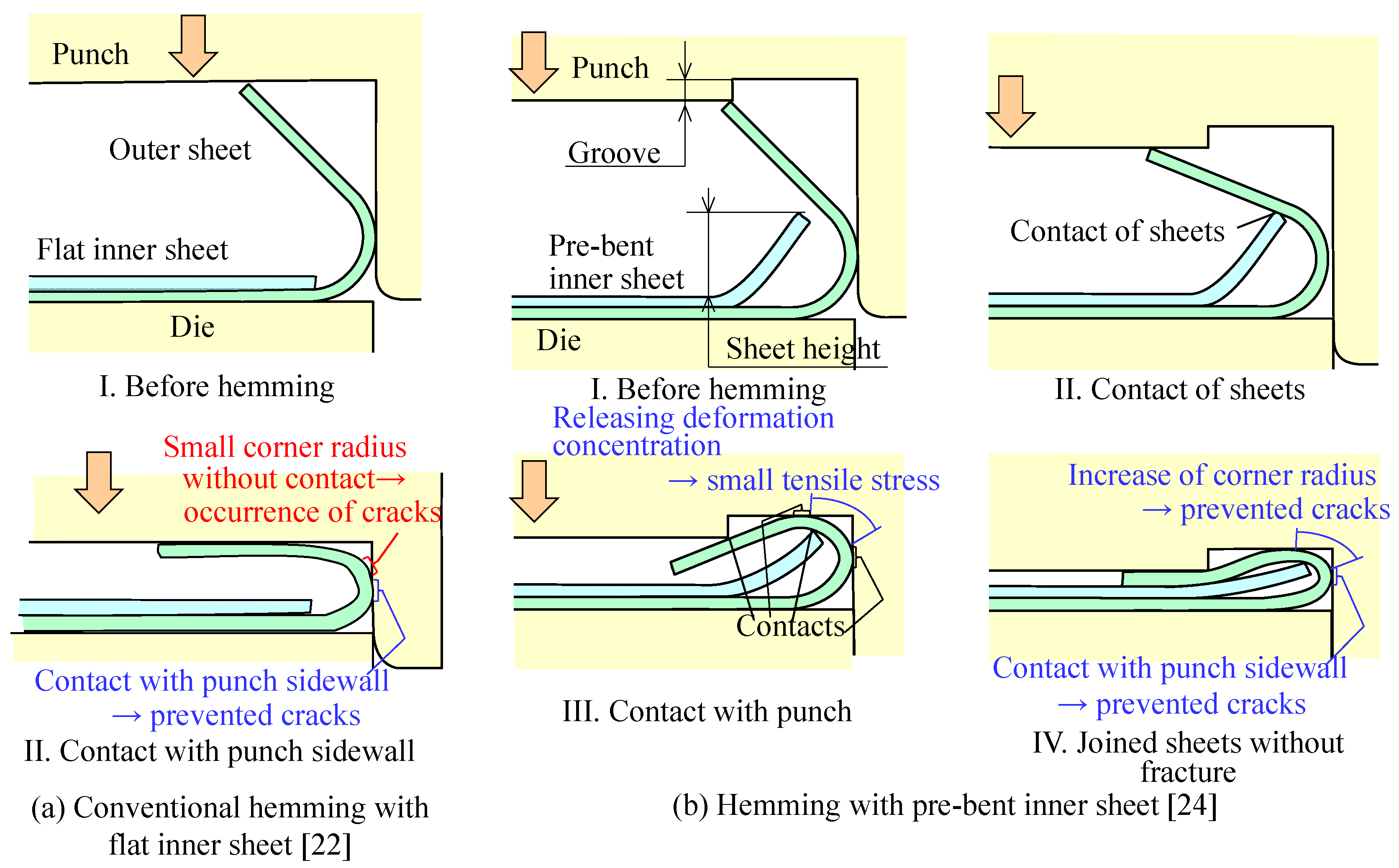
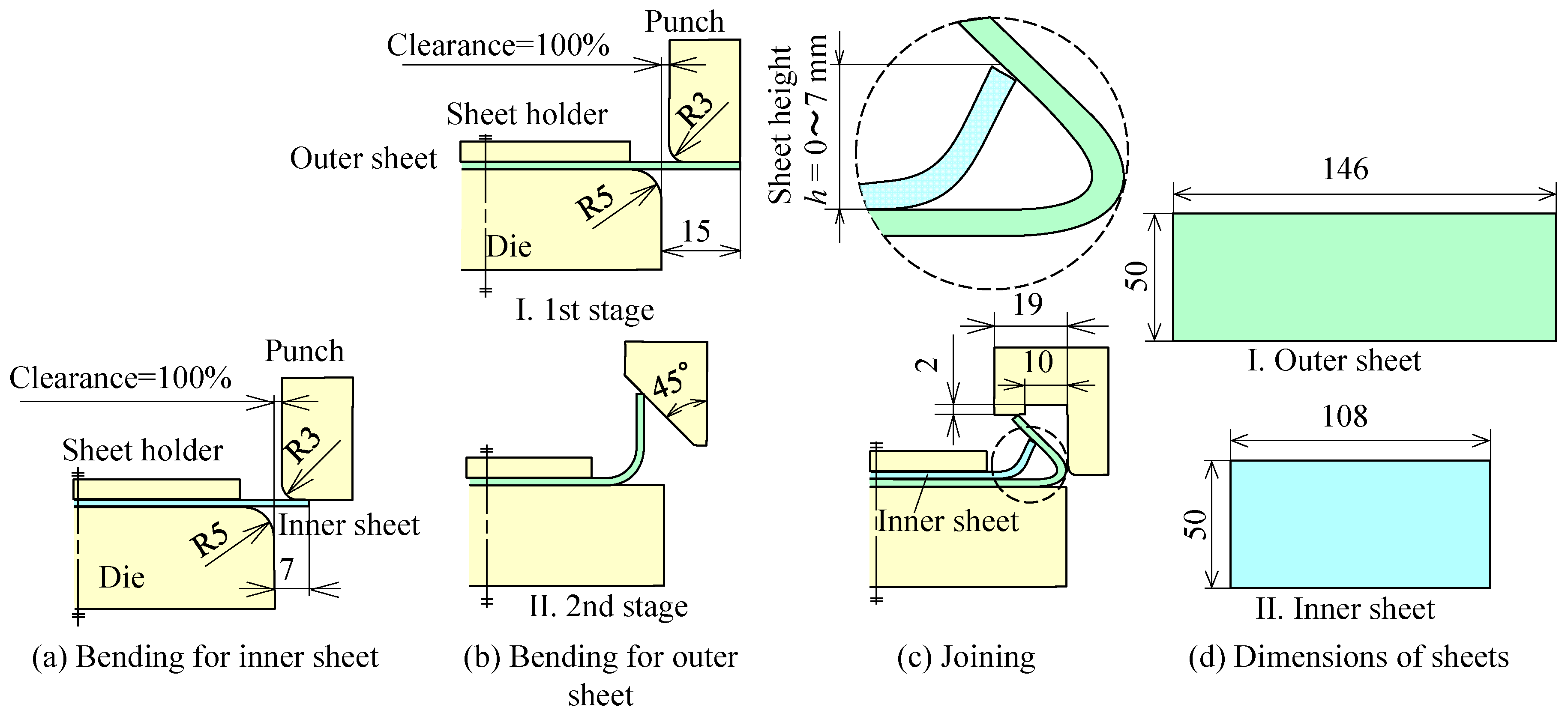
2. Joining Sheets by Hemming with Pre-Bent Inner Sheet

In the hemming process, the edge of the sheet is fold over itself, and two sheets can be joined by folding the outer sheet over with the inserted flat inner sheet. Cracks appear at the outer surface of the outer sheet being bent when the limit of the sheet ductility is reached. Because the cracks sometimes bring fracture, the folding over sheet without the cracks is required. The cracks are caused by high tensile stress and appear at the outer surface on the bend corner where the highest tensile stress appears. In the conventional hemming process in stamping, the punch sidewall contacts with the outer surface on the bend corner to reduce the tensile stress in Figure 1a. Although the cracks on the contacting corner are prevented, the high tensile stress still remains around the contact with the corner—i.e., this process is not enough to join the sheets with low ductility, such as the ultra-high strength steel sheets. In hemming, with a pre-bent inner sheet, shown in Figure 1b, the pre-bent inner sheet with a punch with a groove is used instead of the flat inner sheet and the flat punch. During folding over, not only the punch, but also the pre-bent inner sheet contacts with the outer sheet. The deformation concentration is released by contacting, and then the occurrence of cracks is prevented by the increased corner radius. The top surface of the joined sheets is not flat due to the punch groove, whereas the top surface joined by the conventional hemming process is flat. Because the sheet is usually formed in the stamping process before joining, the number of joining stages does not increase if pre-bending is included in the stamping process.
The material properties of the ultra-high strength steel and high strength steel sheets used in this paper are shown in Table 1. The sheets are dual-phase steel sheets. The material properties were measured by uniaxial tension test with a screw-driven-type universal testing instrument (SHIMADZU Co., Autograph AGS-J). The ductility of the sheet decreases with the increase in the tensile strength.

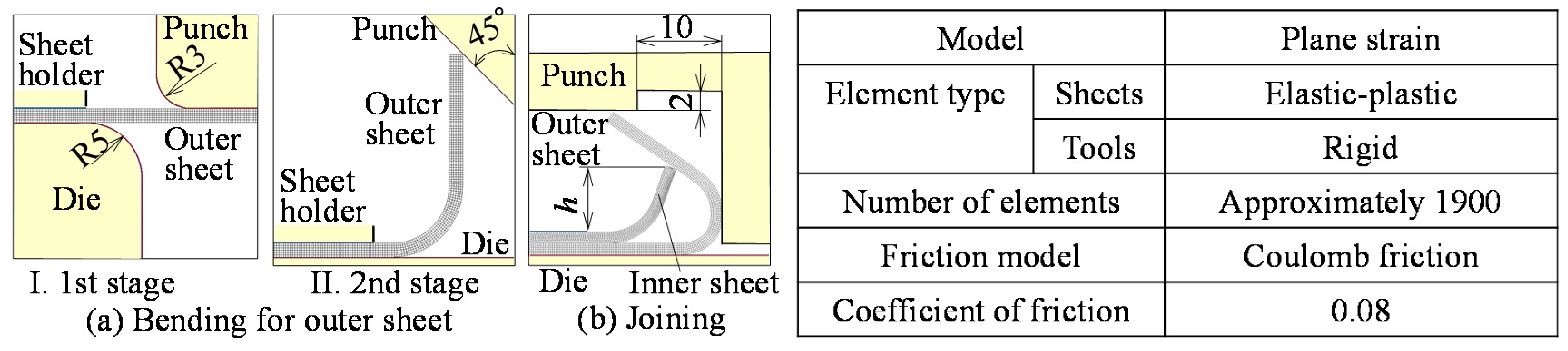
3. Joining Conditions by Hemming

The joining conditions of sheets by hemming with the pre-bent inner sheet are shown in Figure 2. In bending the inner sheet, the sheet height h is controlled by the punch stroke, and h = 0 mm means the flat sheet without bending. The outer sheet is bent to 135° in two stage bending. In joining, the punch with a groove is used, the pre-bent inner and outer sheets were joined. The lengths of outer and inner sheets are 146 mm and 108 mm, respectively, and the flange length is set to the length that is used in a conventional spot weld joint. Because the sheared edge has affected the occurrence of cracks, the effect of the burr side of the sheared edge with 5% in the clearance ratio of sheet thickness was investigated. The sheets were formed by a 150 tonf CNC servo press (AMADA Co., SDE-1522).
The conventional resistance spot welding was performed to join the sheets. The welding conditions and the cross-sectional shape of the welded sheets are shown in Figure 3. The lengths of both sheets are 108 mm. The sheets are joined by a resistance spot welding machine (DAIHEN Co., SLAJS35-601). The diameters of the weld nuggets in all sheets are about 5.8 mm. The coating layer was observed on the electrode after welding, shown in Figure 3d, because the coating layers were melted by heating during welding.
The strain distribution of bend corner in the outer sheet was calculated by a finite element simulation. The conditions in the simulation are shown in Figure 4. The finite element simulation software is LS-DYNA with J-VISION (JSOL Co., Tokyo, Japan). In the finite element simulation, the plane strain condition was assumed. The sheets and tools were assumed as elastic-plastic and rigid bodies, respectively. The coulomb friction in all interfaces was assumed, and the friction coefficient was 0.08. The flow stress of the 1180 MPa sheet was σ = 1750 ε 0.07 MPa, which was obtained by the uniaxial tensile test.

4. Deforming Behavior of Sheets and Improvement of Joining Limit by Hemming with Pre-Bent Inner Sheet

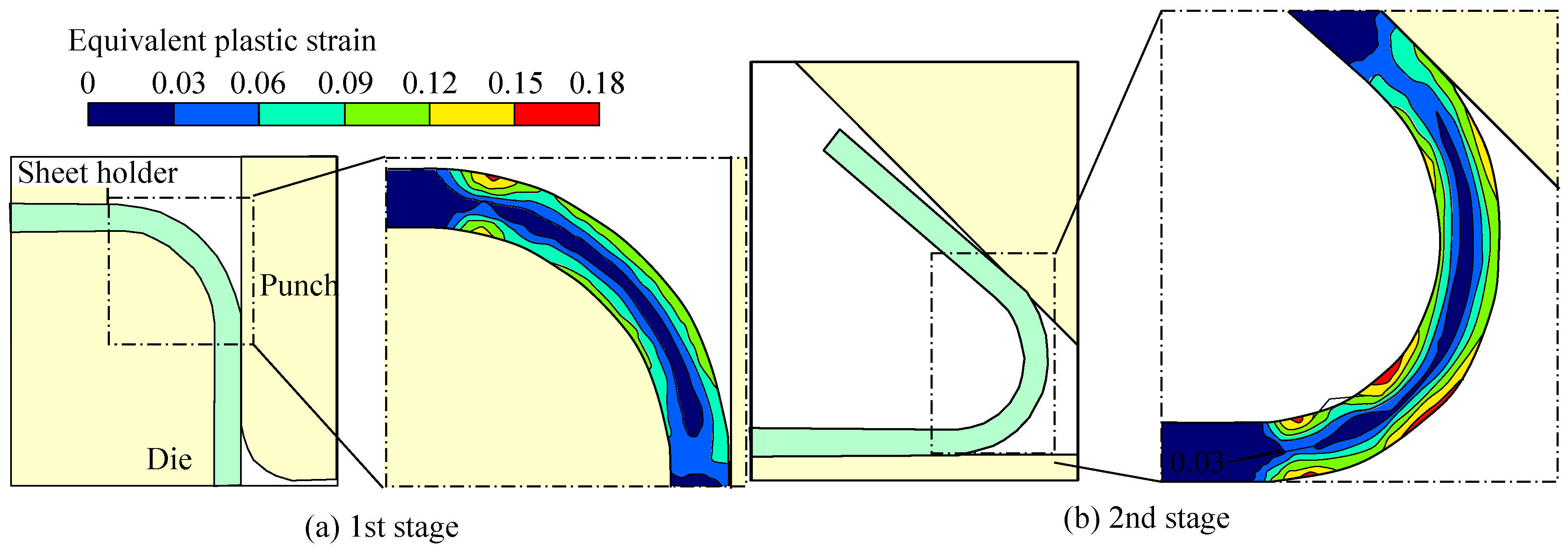
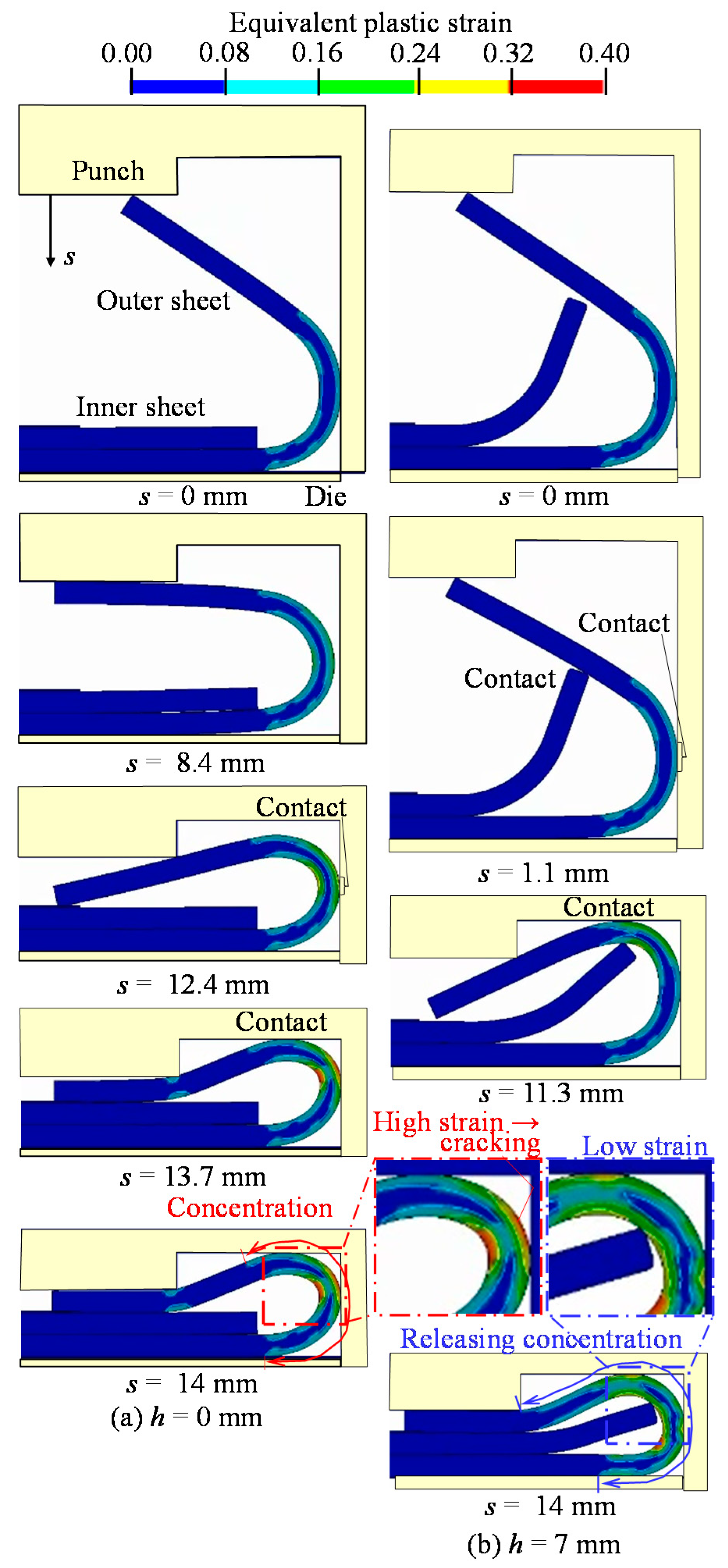
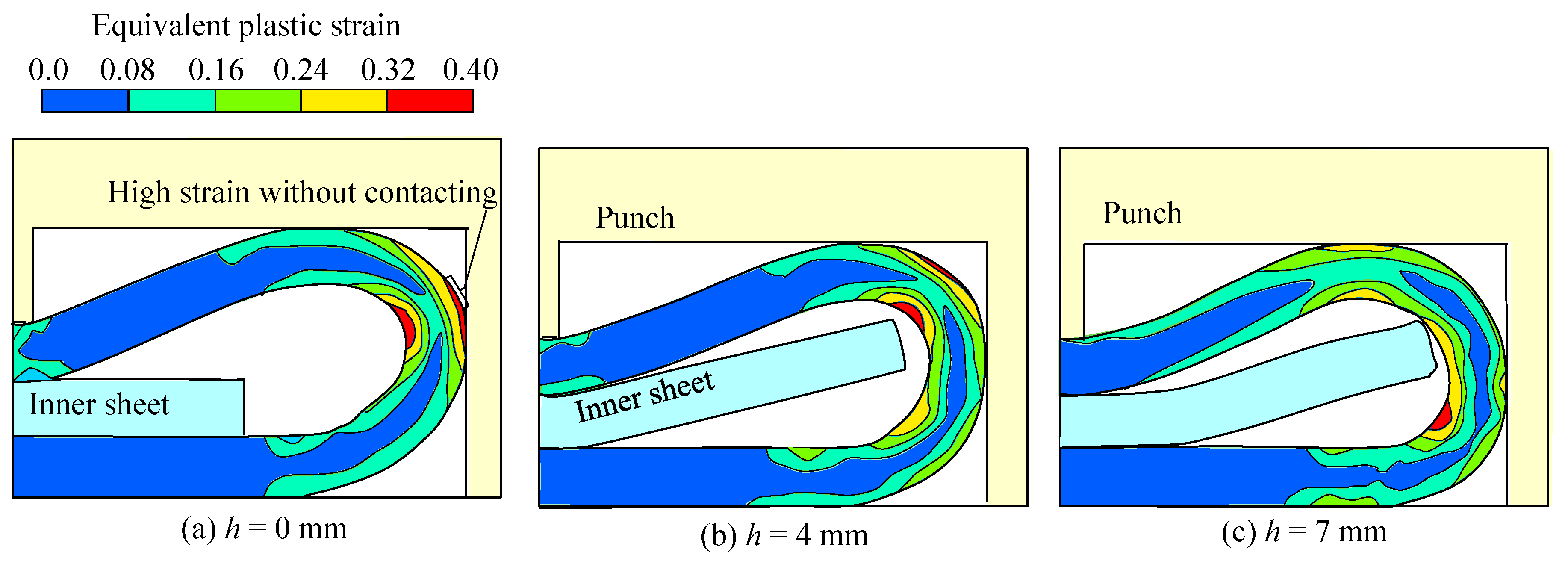
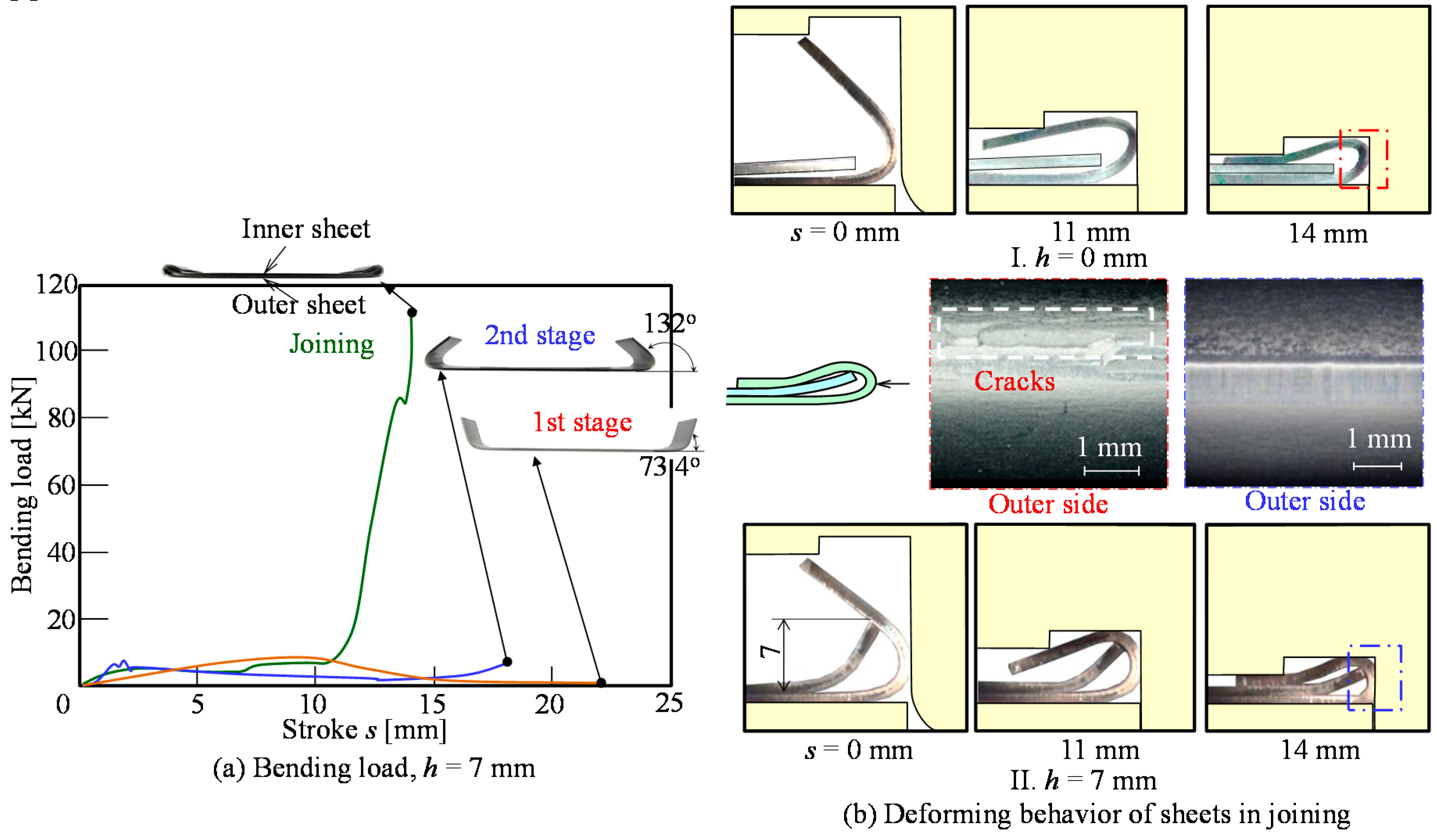
4.1. Deforming Behavior of Sheets

The calculated equivalent plastic strain distribution in the outer sheet of the first and second stages is shown in Figure 5. In the first stage, the maximum strain appears on the bend corner in the top surface. In the second stage, the high strain appears on the surface of the bottom bend corner.
The deforming behaviors of the sheets in the joining stage for h = 0 mm and h = 7 mm in the calculation are shown in Figure 6. In h = 0 mm, the outer sheet contacts with the punch sidewall and the die groove at s = 12.4 mm and 13.7 mm, respectively. In h = 7 mm, the outer sheet contacts with the pre-bent inner sheet and the punch sidewall in the early stage in joining, and contacts with the die groove at s = 11.3 mm. The deformation of the upper sheet is released by contact with the inner sheet and with the punch earlier than that of h = 0 mm, whereas the deformation of outer sheet for h = 0 mm is concentrated and large.
The effect of the sheet height on the plastic strain in the outer sheet in the joining stage is shown in Figure 7. In the final stroke, the high plastic strain on the outer surface of the bend corner is appeared for h = 0 and 4 mm. The maximum strain occurred at the outer surface without contacting with the punch sidewall—i.e., the fracture tends to occur at the portion. In the final stroke for h = 7 mm, the maximum plastic strain on the outer surface is decreased by relaxing the concentration of deformation, the strain reduction is 20%.

4.2. Improvement of Joining Limit in Experiment

The load-stroke curves in the hemming process and the deforming behavior of sheets in the joining stage for 1180 MPa steel sheet are shown in Figure 8. The loads in the first and second stages are low. The load in the joining stage is high to compress the sheets. The bend angle after first stage is larger than the tool angle due to the springback. Although the bend angle after second stage is larger, the springback angle is small. After the joining stage, the outer sheet is folded over without the springback. The sheets are successfully joined without defects in h = 7 mm, whereas the cracks appear on the outer surface in h = 0 mm.
The sheared edge of the steel sheet is shown in Figure 9. The sheared edge consists of the rollover, burnished surface, fracture surface and small burr. The ratio of burnished surface decreases with increasing the tensile strength of the sheet due to low ductility.
The effect of the burr direction on cracks on the sheet edge is shown in Figure 10. On 780 MPa steel sheets with high ductility, the conventional hemming process was used. The cracks are not observed for 780 MPa, h = 0 mm and the inner burr, and the upper sheet surface of joined sheets was flat. The cracks are observed in the burr outside, whereas the occurrence of cracks is prevented in the burr inside in 980 MPa and 1180 MPa. The cracks were caused in the burr outside of the fracture surface that was greatly damaged in shearing. To improve the bendability, the sheared edge in the burr inside is used in joining.
The joining range by hemming is shown in Figure 11. Because the 780 MPa sheet has high ductility, the sheets are joined without the pre-bent inner sheet. The sheet height to join without the cracks increases with the increase in the tensile strength of the sheet. However, the ultra-high strength steel sheets are successfully joined by hemming with the pre-bent inner sheet.
The minimum bend radius ratio of the steel sheet without the cracks is shown in Table 2. Because the 780 MPa sheet has high ductility, the minimum bend radius ratio is the smallest. The minimum bend radius ratio for the ultra-high strength steel sheets is higher, and more than twice that of the sheet thickness.
The distributions of the wall thickness and coating layer thickness in the joined outer sheet for 1180 MPa steel sheets are shown in Figure 12. The wall thickness was reduced by bending and especially the reduction in wall thickness in the contact portion with the punch sidewall is large. The coating layer thickness disappears in the contact portion with punch sidewall. In the welded sheets, the coating layer thickness was reduced in the contact portion, and the coating layer was deposited on the electrode by melting in welding (see Figure 3d).
The hardness distributions in the hemmed and welded 1180 MPa steel sheets are shown in Figure 13. The hardness in the hemmed outer sheet increased by plastic deformation in hemming. The hardness under the contact portion with the electrode increased by quenching, whereas the hardness around the weld nugget decreased by annealing in the welded sheets.

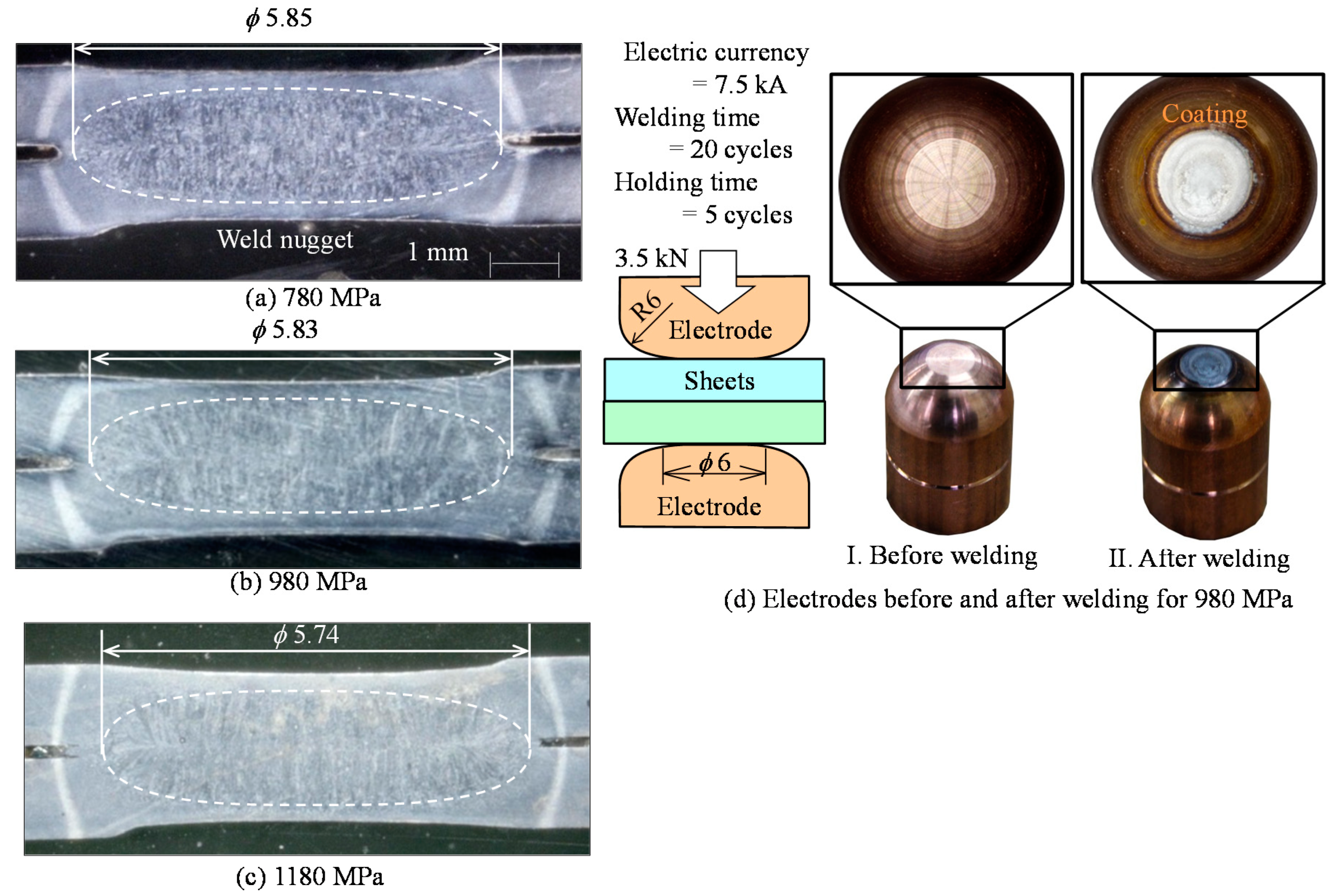
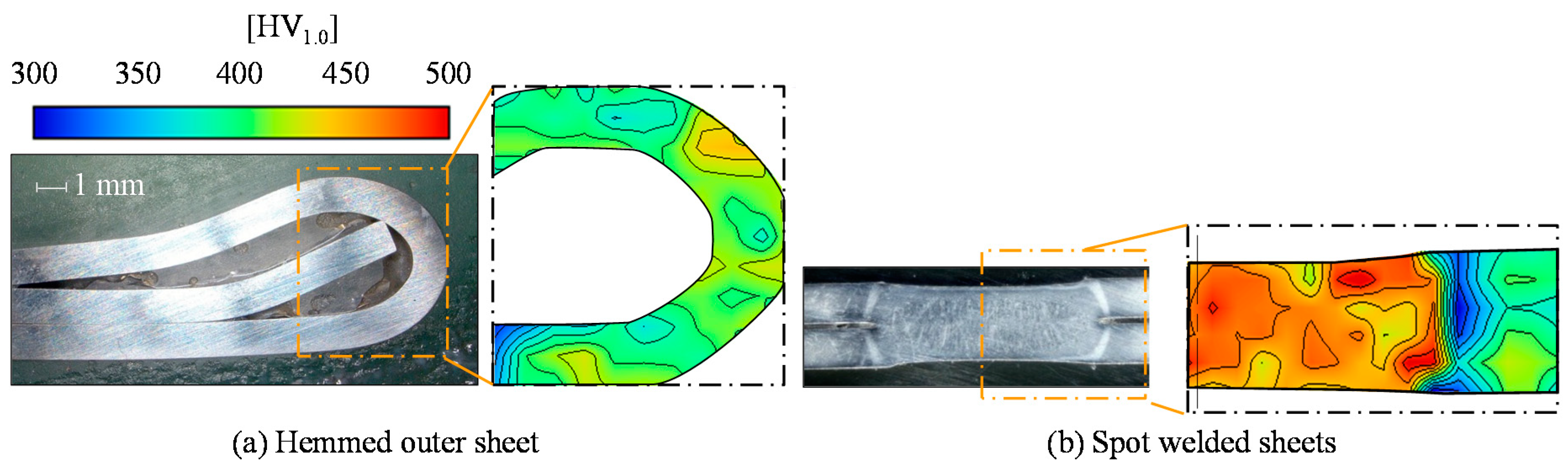
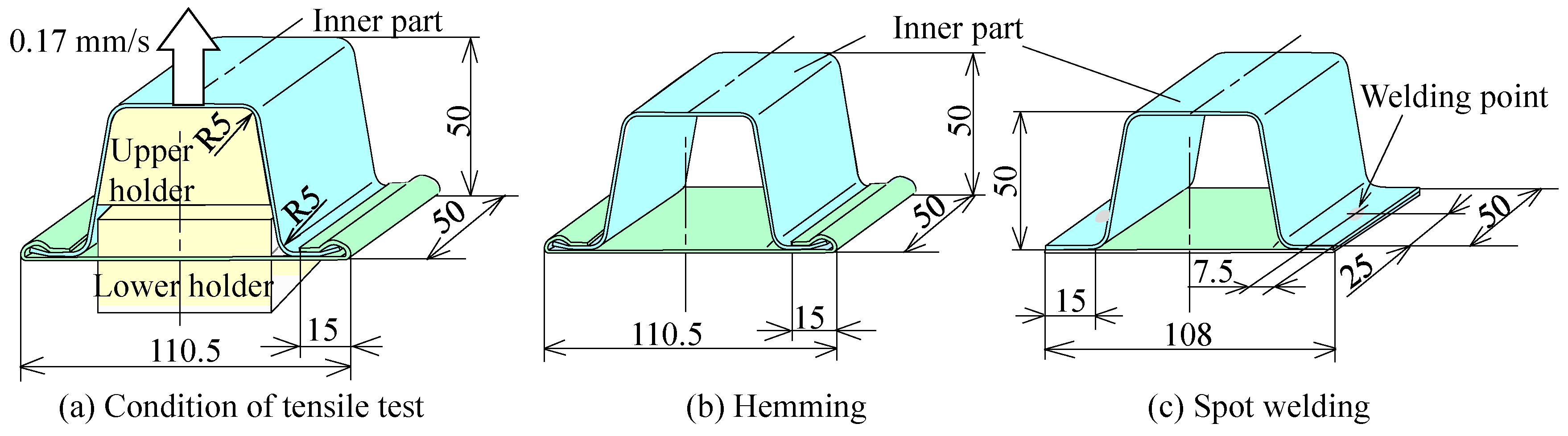
5. Joint Strength of Joined Sheets

The joint strength of the sheets was investigated and the conditions of the test are shown in Figure 14a. The sheets are joined in two flanges. The length and width of joint are 50 mm and 15 mm, respectively. In the welded sheets, the sheets are joined in the flange center by a weld nugget on the side. The upper sheet was pulled to upward, and the tension load and stoke were measured.
The load-stroke curve in the tensile test for the joined 1180 MPa steel sheets is shown in Figure 15. The load for the hemmed sheets increases with increasing the stroke, and then the inner sheets in flanges were pulled out from the opened outer sheets. In the welded sheets, the fracture occurred around the weld nuggets. The maximum load of the welded sheets is higher than that of the hemmed sheets.
The maximum tensile load of the joined sheets is shown in Figure 16. The maximum tensile loads of both the hemmed and welded sheets increase by increasing the tensile strength of the sheet. However, the maximum tensile load of the hemmed sheets is about a half of that of the welded sheets.

6. Conclusions

In this study, the deforming behavior of the sheets was investigated in the joining process of steel sheets for automobile body parts by hemming with the pre-bent inner sheet. The results of this study are summarized as follows:
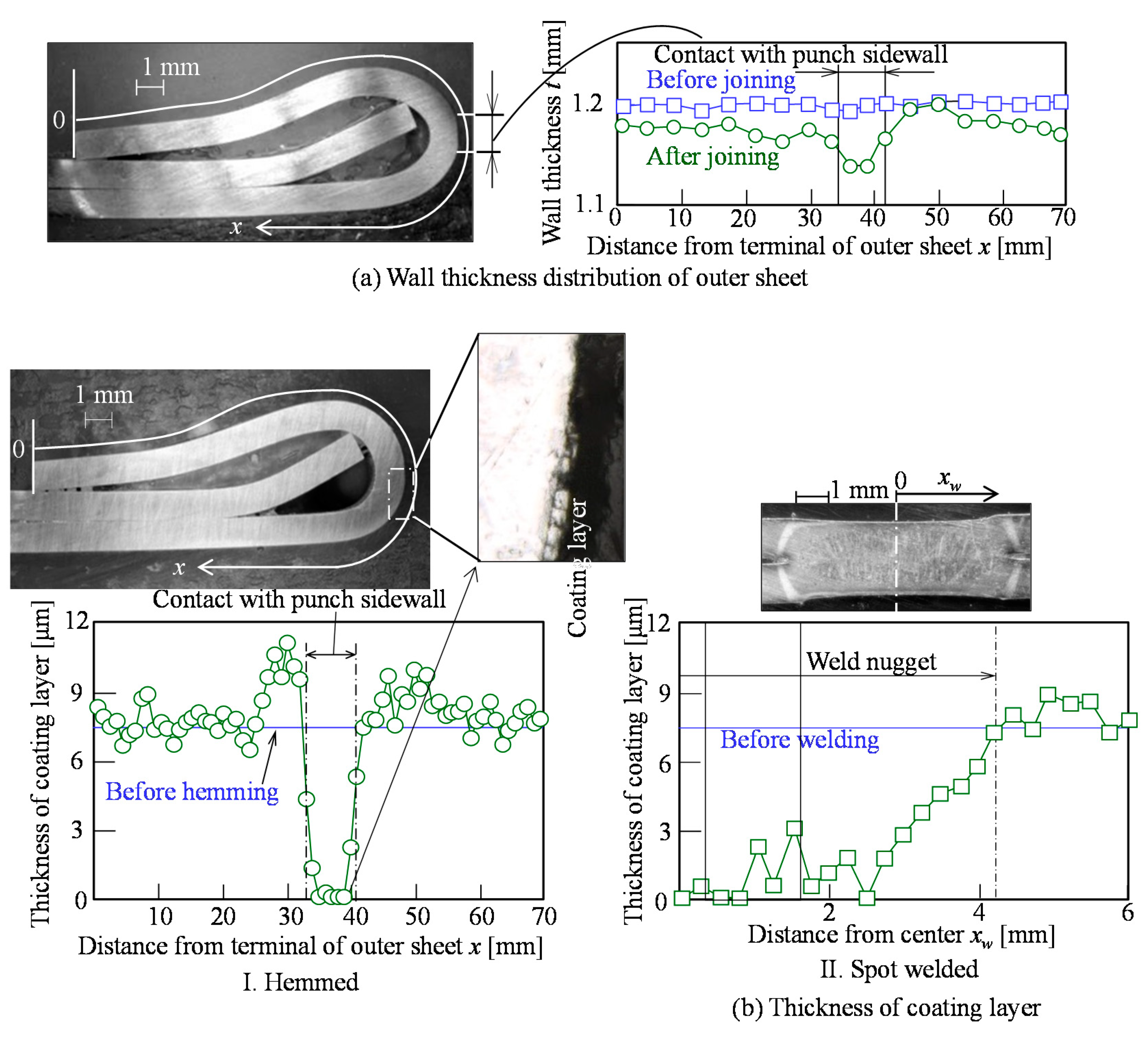
  • The maximum plastic strain on the outer surface in hemming with the pre-bent inner sheet was decreased by releasing the concentration of deformation, and the strain reduction was 20%.
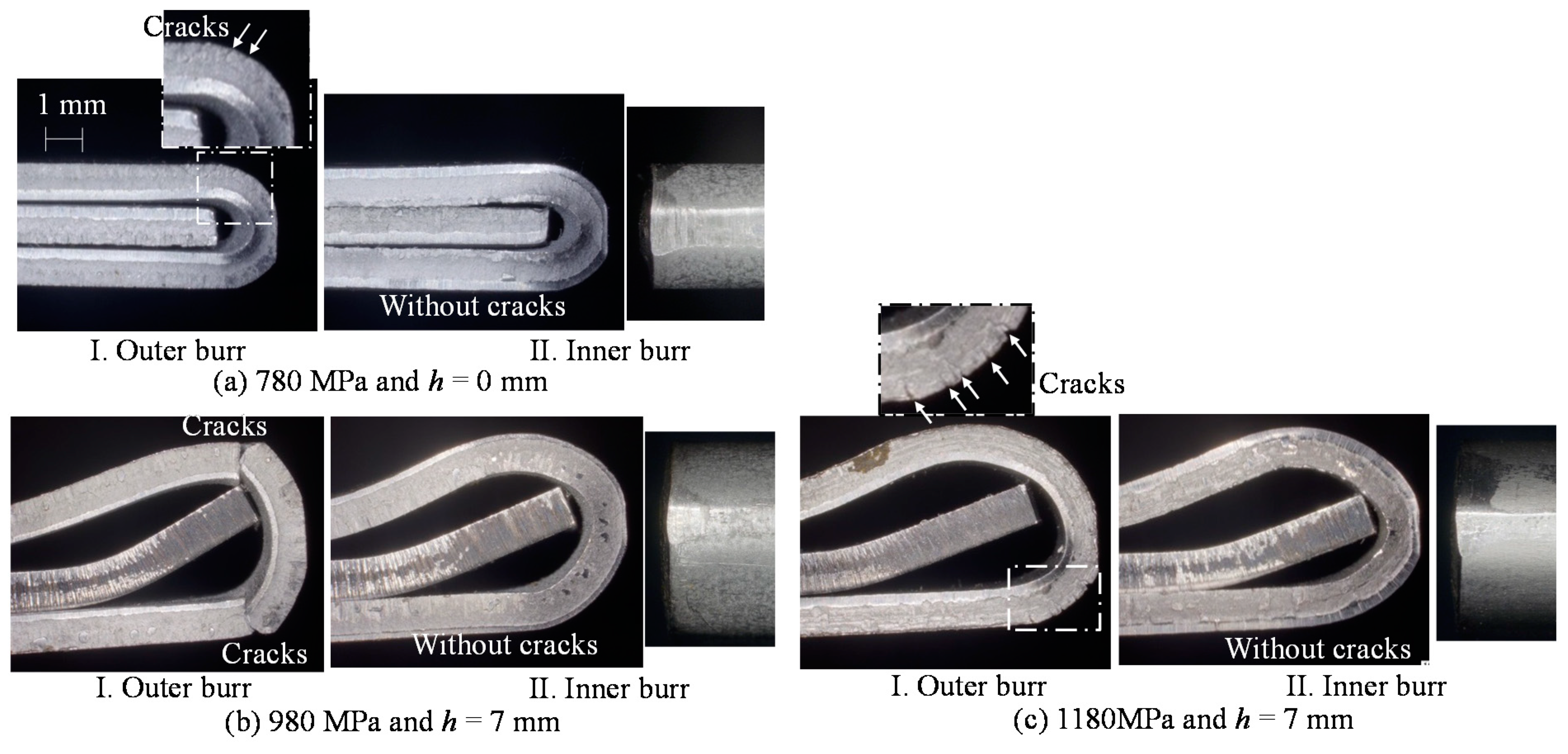
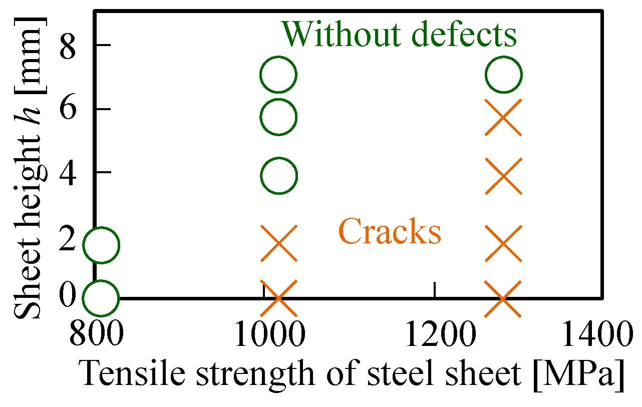
  • Although 780 MPa steel sheets with a 1.5 in minimum bend radius ratio were joined by conventional hemming without the pre-bent inner sheet, 1180 MPa steel sheets with a 2.25 minimum bend radius ratio were joined by hemming with the pre-bent inner sheet.
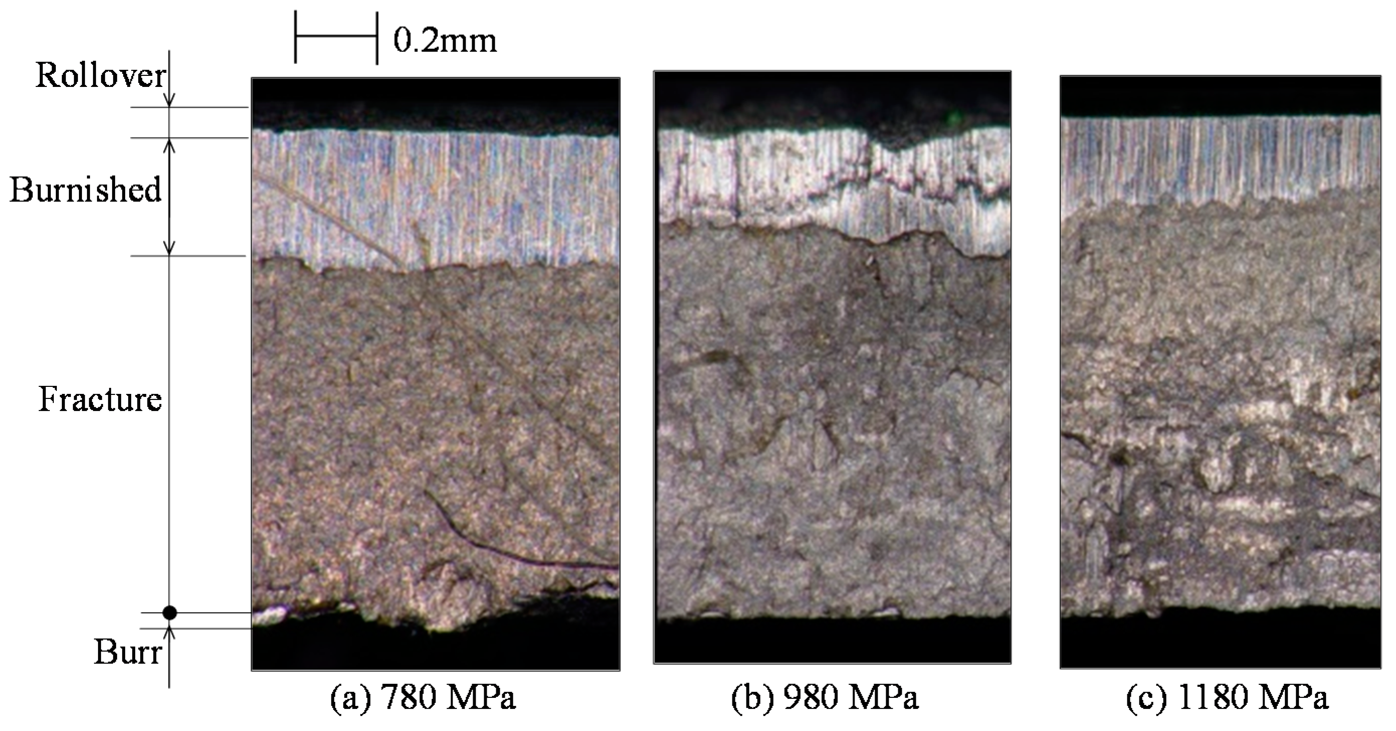
  • The formability of sheared edge was influenced to the occurrence of cracks in hemming, the occurrence was prevented in the burr inside the 980 MPa and 1180 MPa steel sheets, whereas the effect of the sheared edge on the formability of 780 MPa steel sheet with high ductility was small.
  • The maximum load of the hemmed sheets in the tensile test was about a half of that of the welded sheets, although the maximum tensile loads of both hemmed and welded sheets increased by increasing the tensile strength of the sheet.
The hemming process with the pre-bent inner sheet is suitable for assembling automobile parts including the ultra-high strength steel sheets. As an inner sheet, not only the ultra-high strength steel sheet used in this study, but also a dissimilar material, such die-quenched steel, aluminum alloy or carbon fiber reinforced plastic is useful. The assembled parts using the high specific strength sheets are effective for improving the lightweight and the collision safety of automobiles without a cost increment if pre-bending is included in the stamping process before joining.

Author Contributions

Conceptualization, Y.A. and W.I.; methodology and investigation, W.I. and K.N.; writing—original draft preparation, Y.A.; visualization, W.I., Y.A. and K.N.; supervision, K.-i.M. All authors have read and agreed to the published version of the manuscript.

Funding

This work was supported by Japan Society for the Promotion of Science Grants-in-Aid for Scientific Research Grant-in-Aid for Scientific Research (C) Grant Number 26420048. This work was supported by the Suzuki Foundation.

Conflicts of Interest

The authors declare no conflict of interest.

References

  1. Kleiner, M.; Geiger, M.; Klaus, A. Manufacturing of Lightweight Components by Metal Forming. Ann. CIRP 2003, 52, 521–542. [Google Scholar] [CrossRef]
  2. Parker, J.; Williams, N.; Holliday, R. Mechanisms of Electrode Degradation When Spot Welding Coated Steels. Sci. Technol. Weld. Join. 1998, 3, 65–74. [Google Scholar] [CrossRef]
  3. Ling, Z.; Wang, M.; Kong, L. Liquid Metal Embrittlement of Galvanized Steels during Industrial Processing: A Review. In Transactions on Intelligent Welding Manufacturing; Springer: Singapore, 2018; pp. 25–42. [Google Scholar] [CrossRef]
  4. Zhang, W.H.; Qiu, X.M.; Sun, D.Q.; Han, L.J. Effects of Resistance Spot Welding Parameters on Microstructures and Mechanical Properties of Dissimilar Material Joints of Galvanised High Strength Steel and Aluminium Alloy. Sci. Technol. Weld. Join. 2011, 16, 153–161. [Google Scholar] [CrossRef]
  5. Mori, K.; Kato, T.; Abe, Y.; Ravshanbek, Y. Plastic Joining of Ultra High Strength Steel and Aluminium Alloy Sheets by Self Piercing Rivet. Ann. CIRP 2006, 55, 283–286. [Google Scholar] [CrossRef]
  6. Mori, K.; Abe, Y. A Review on Mechanical Joining of Aluminium and High Strength Steel Sheets by Plastic Deformation. Int. J. Lightweight Mater. Manuf. 2018, 1, 1–11. [Google Scholar] [CrossRef]
  7. Okunaka, K.; Tao, S.; Fujita, S.; Kobayashi, K.; Shiobara, K. Technical Development of the 3D Lock Seam Applied to New Acura RLX Doors. J. Jpn. Soc. Technol. Plast. 2014, 55, 1073–1077. (In Japanese) [Google Scholar] [CrossRef]
  8. Kalpakjian, S.; Schmid, S. Manufacturing Engineering & Technology, 7th ed.; Pearson Education South Asia Pte Ltd.: Singapore, 2013; p. 410. [Google Scholar]
  9. Neugebauer, R.; Drossel, W.G.; Rössinger, M.; Eckert, A.; Hecht, B. Roller Hemming Simulation: State of the Art and Application Limits. Key Eng. Mater. 2014, 611, 1062–1070. [Google Scholar] [CrossRef]
  10. Livatyali, H.; Larris, S.J. Experimental Investigation on Forming Defects in Flat Surface—Convex Edge Hemming Roll, Recoil and Warp. J. Mater. Process. Technol. 2004, 153, 913–919. [Google Scholar] [CrossRef]
  11. Thuillier, S.; Le Maoût, N.; Manach, P.Y.; Debois, D. Numerical simulation of the roll hemming process. J. Mater. Process. Technol. 2008, 198, 226–233. [Google Scholar] [CrossRef]
  12. Li, S.; Hu, X.; Zhao, Y.; Lin, Z.; Xu, N. Cyclic Hardening Behavior of Roller Hemming in the Case of Aluminum Alloy Sheets. Mater. Des. 2011, 32, 2308–2316. [Google Scholar] [CrossRef]
  13. Le Maoût, N.; Thuillier, S.; Manach, P.Y. Aluminum Alloy Damage Evolution for Different Strain Paths—Application to Hemming Process. Eng. Fract. Mech. 2009, 76, 1202–1214. [Google Scholar] [CrossRef]
  14. Hu, X.; Lin, Z.Q.; Li, S.H.; Zhao, Y.X. Fracture Limit Prediction for Roller Hemming of Aluminum Alloy Sheet. Mater. Des. 2010, 31, 1410–1416. [Google Scholar] [CrossRef]
  15. Le Maoût, N.; Manach, P.Y.; Thuillier, S.J. Influence of Prestrain on the Numerical Simulation of the Roller Hemming Process. Mater. Process. Technol. 2012, 212, 450–457. [Google Scholar] [CrossRef] [Green Version]
  16. Zhang, G.; Wu, X.; Jack Hu, S. A Study on Fundamental Mechanisms of Warp and Recoil in Hemming. J. Eng. Mater. Technol. 2000, 123, 436–441. [Google Scholar] [CrossRef]
  17. Zhang, G.; Hao, H.; Wu, X.; Jack Hu, S.; Harper, K.; Faitel, W. An Experimental Investigation of Curved Surface-Straight Edge Hemming. J. Manuf. Process. 2000, 2, 241–246. [Google Scholar] [CrossRef]
  18. Svensson, M.; Mattiasson, K. Three-Dimensional Simulation of Hemming with the Explicit FE-Method. J. Mater. Process. Technol. 2002, 128, 142–154. [Google Scholar] [CrossRef]
  19. Terada, K.; Takahashi, S.; Takai, R. Development of Prediction of Surface Accuracy in Hemmed Parts by Springback Simulation. J. Jpn. Soc. Technol. Plast. 2010, 51, 963–968. (In Japanese) [Google Scholar] [CrossRef]
  20. Livatyali, H.; Müderrisoğlu, A.; Ahmetoğlu, M.A.; Akgerman, N.; Kinzel, G.L.; Altan, T. Improvement of Hem Quality by Optimising Flanging and Pre-Hemming Operations Using Computer Aided Process and Die Design. J. Mater. Process. Technol. 2000, 98, 41–52. [Google Scholar] [CrossRef]
  21. Golovashchenko, S.F. Sharp Flanging and Flat Hemming of Aluminum Exterior Body Panels. J. Mater. Eng. Perform. 2005, 14, 508–515. [Google Scholar] [CrossRef]
  22. Hamedon, Z.; Mori, K.; Abe, Y. Hemming for Joining High Strength Steel Sheets. Proc. Eng. 2014, 81, 2074–2079. [Google Scholar] [CrossRef]
  23. Kleeh, T.; Merklein, M.; Roll, K. Modeling Laser Heating for Roller Hemming Applications. Key Eng. Mater. 2011, 473, 501–508. [Google Scholar] [CrossRef]
  24. Abe, Y.; Mori, K.; Nakagawa, K. Assembly of Ultra-High Strength Steel Hollow Part by Hemming Using Pre-Bent Inner Sheet. Proc. Eng. 2017, 207, 974–979. [Google Scholar] [CrossRef]
Figure 1. Prevention of crack in joining sheets by hemming with flat inner and pre-bent inner sheets [22,24].
Jmmp 04 00077 g001
Figure 2. Joining conditions of sheets by hemming with pre-bent inner sheet.
Jmmp 04 00077 g002
Figure 3. Conditions of resistance spot welding and welded sheets.
Jmmp 04 00077 g003
Figure 4. Calculated conditions of hemming with relaxation of deformation and compression of outer sheet.
Jmmp 04 00077 g004
Figure 5. Calculated equivalent plastic strain distribution in outer sheet of first and second stages.
Jmmp 04 00077 g005
Figure 6. Deforming behaviors of sheets in joining stage for h = 0 mm and h = 7 mm in calculation.
Jmmp 04 00077 g006
Figure 7. Effect of sheet height on plastic strain in outer sheet in joining stage.
Jmmp 04 00077 g007
Figure 8. Load–stroke curves in hemming process and deforming behavior of sheets in third stage for 1180 MPa steel sheets and inner burr.
Jmmp 04 00077 g008
Figure 9. Sheared edge of steel sheet.
Jmmp 04 00077 g009
Figure 10. Effect of burr direction on cracks on sheet edge.
Jmmp 04 00077 g010
Figure 11. Joining range by hemming.
Jmmp 04 00077 g011
Figure 12. Distributions of wall thickness and coating layer thickness in joined outer sheet for 1180 MPa steel sheets.
Jmmp 04 00077 g012
Figure 13. Hardness distributions in hemmed and welded 1180 MPa steel sheets.
Jmmp 04 00077 g013
Figure 14. Conditions and geometries of specimen in tensile test.
Jmmp 04 00077 g014
Figure 15. Load–stroke curve in tensile test for joined 1180 MPa steel sheets.
Jmmp 04 00077 g015
Figure 16. Maximum load in tensile test.
Jmmp 04 00077 g016
Table 1. Material properties of ultra-high strength steel and high strength steel sheets.
Sheet1180 MPa980 MPa780 MPa
JSC1180JAC980JAC780
Coating-Galvanized alloy
Thickness [mm]1.201.211.20
0.2% Proof stress [MPa]1003605489
Tensile strength [MPa]12871029799
Reduction in area [%]51.852.462.5
Table 2. Minimum bend radius ratio of steel sheets.
Hemming780 MPa980 MPa1180 MPa
Flat inner sheet
(h = 0 mm)
Without defectCracksCracks
Pre-bent inner sheetWithout defect
(h ≥ 0 mm)
Without defect
(h ≥ 4 mm)
Without defect
(h ≥ 7 mm)
Minimum bend radius/sheet thickness [-]1.52.082.25

