Electrohydrodynamic Atomization for Minimum Quantity Lubrication (EHDA-MQL) in End Milling Ti6Al4V Titanium Alloy


Abstract
1. Introduction
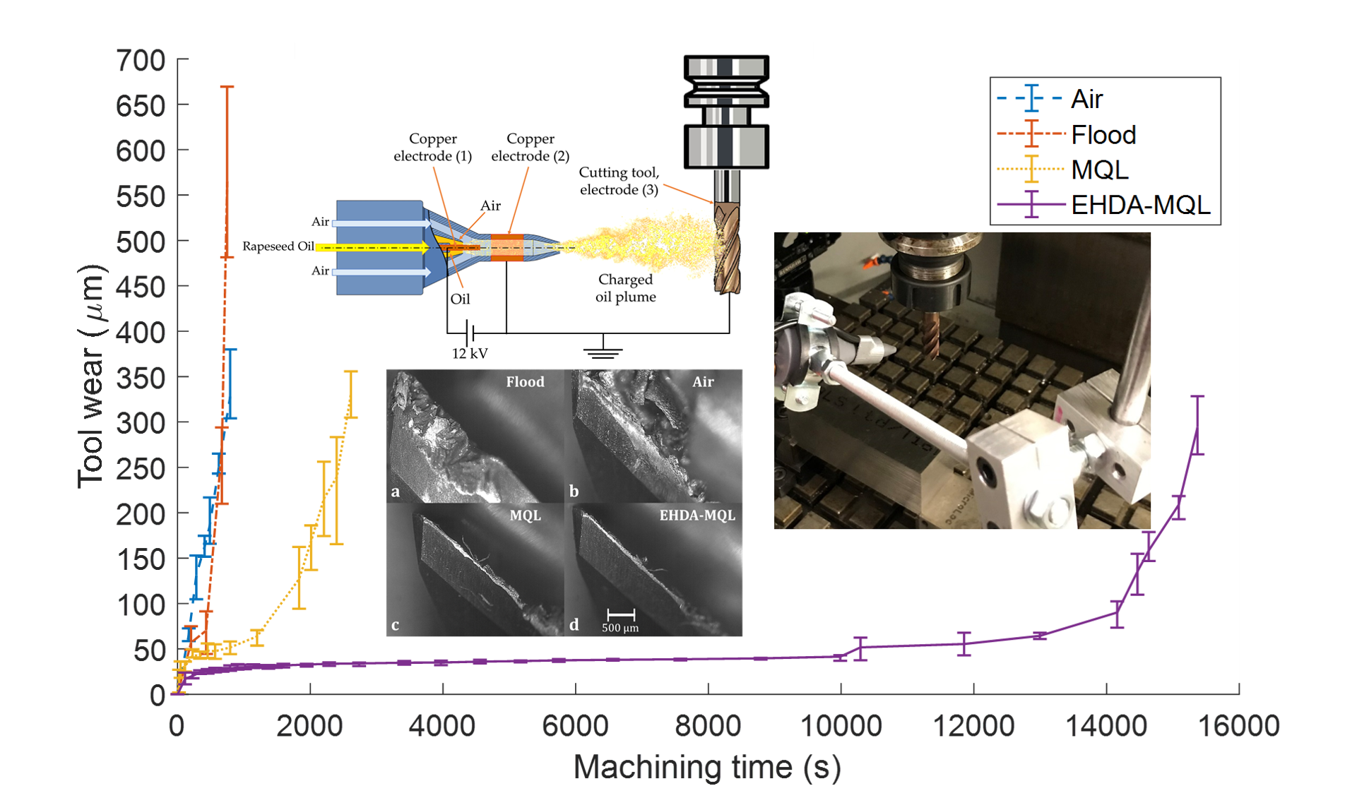
2. Electrohydrodynamic Atomization Minimum Quantity Lubrication (EHDA-MQL) System
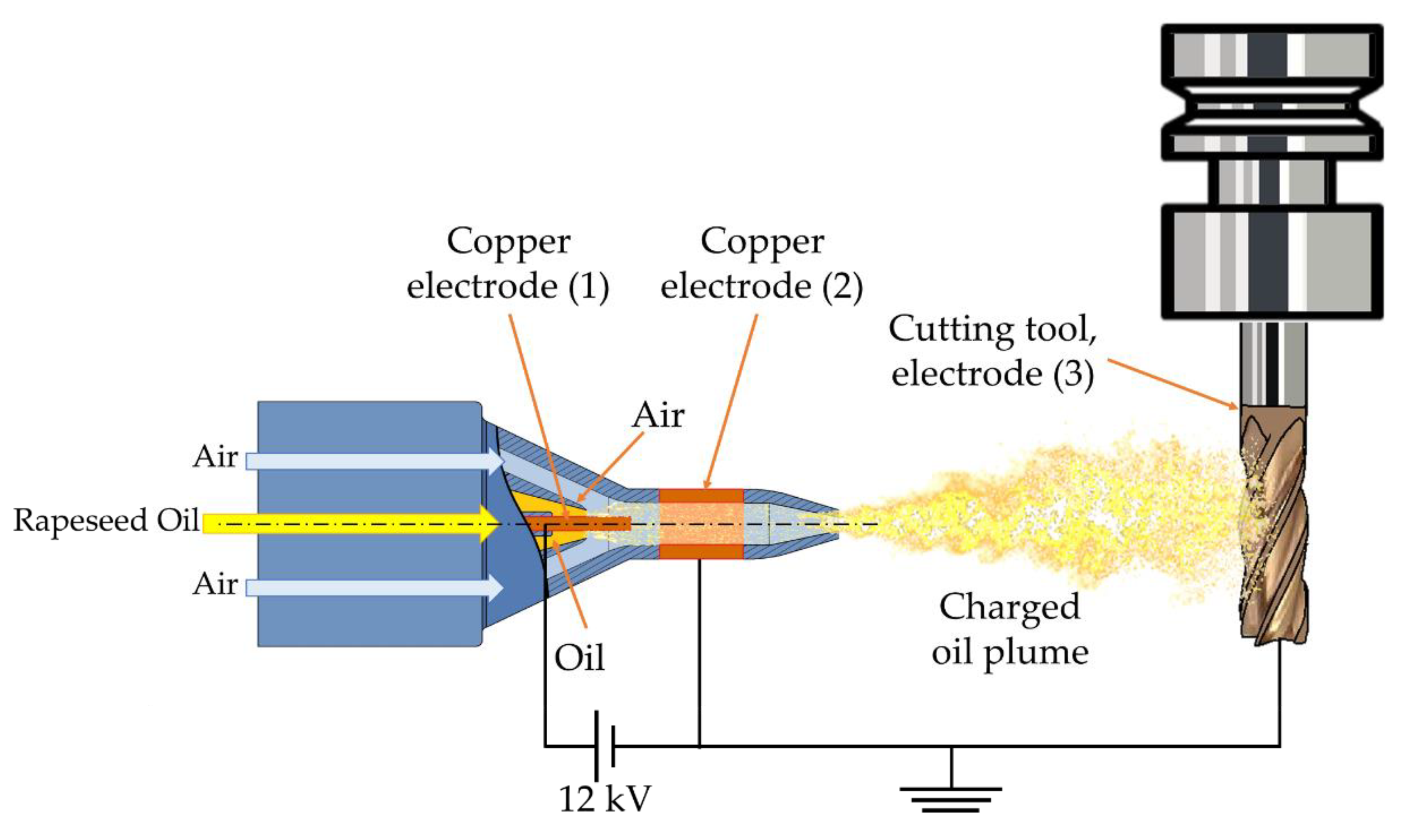
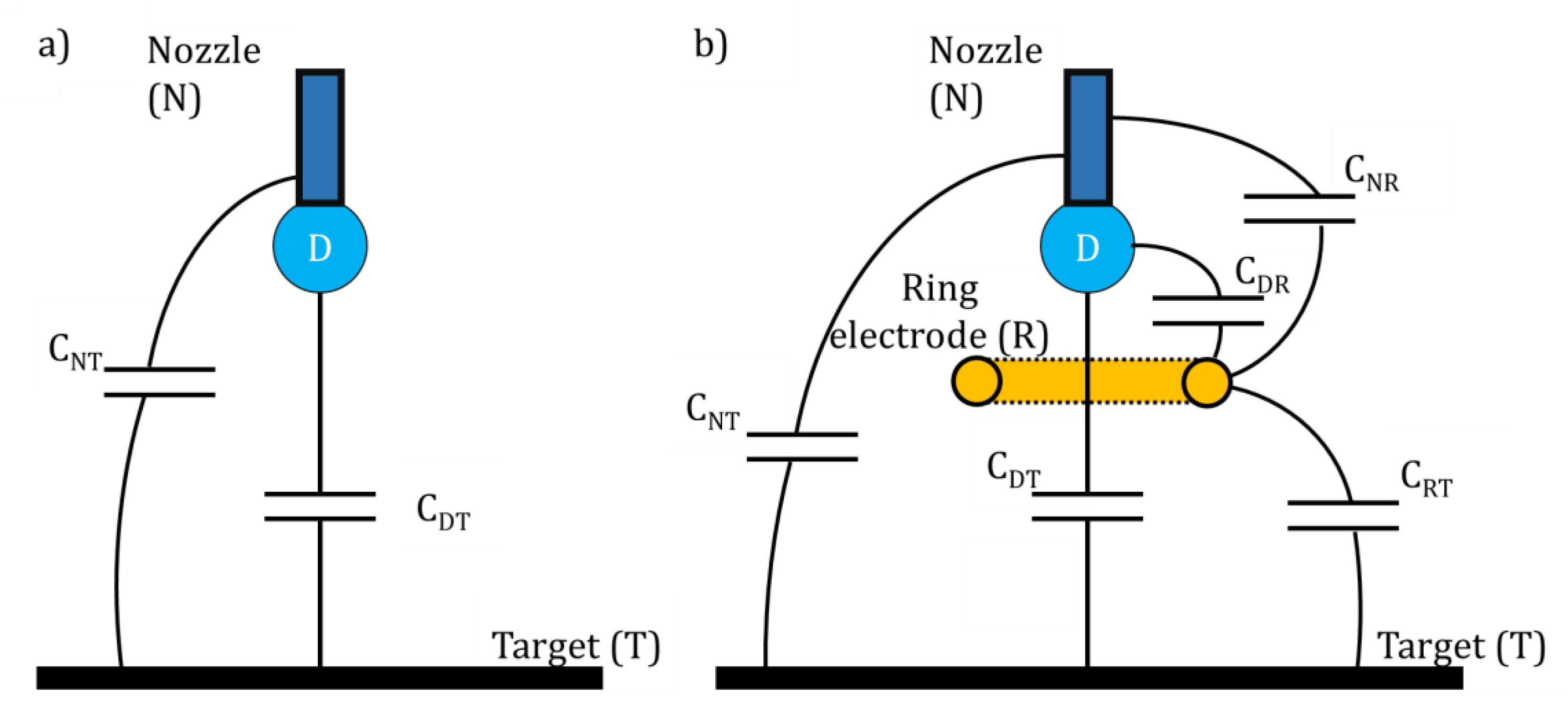
Governing Theory
3. Methodology
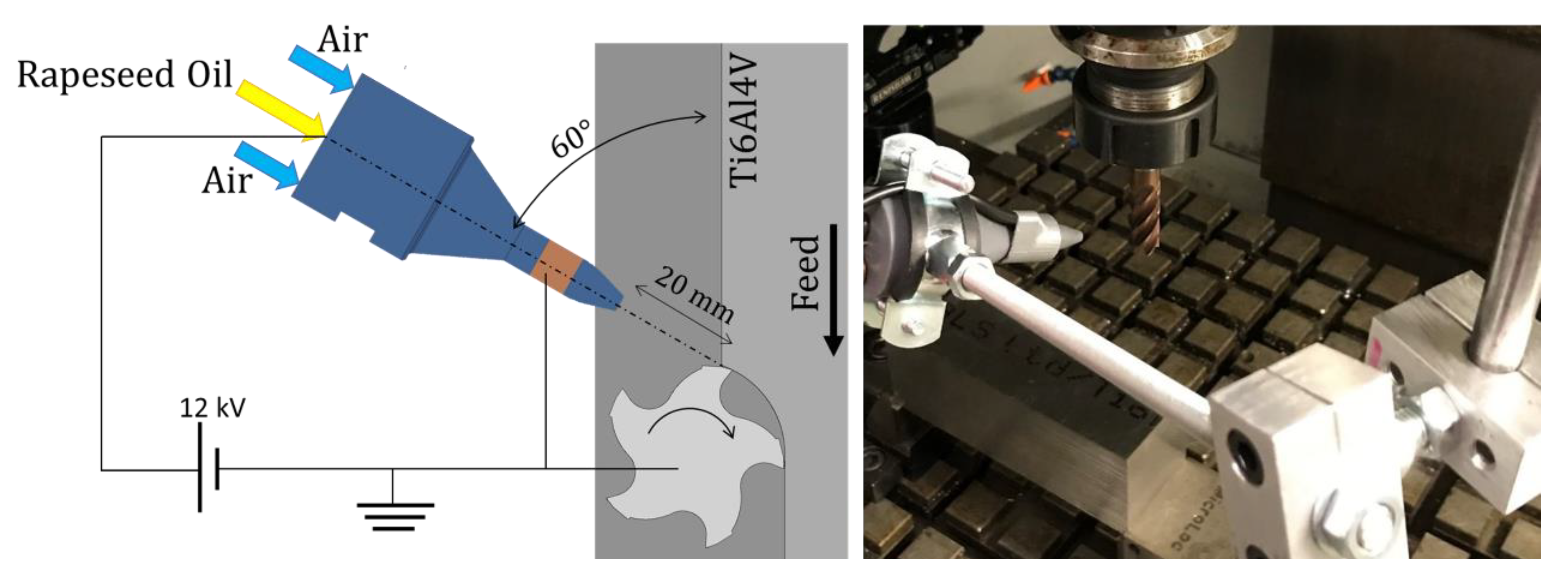
Experimental Setup
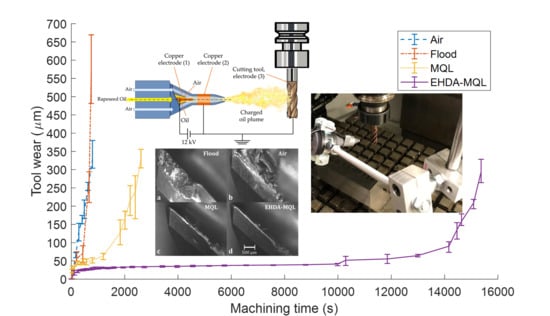
4. Results and Discussion
5. Conclusions
Author Contributions
Funding
Acknowledgments
Conflicts of Interest
References
- Umbrello, D.; Rotella, G. Fatigue life of machined ti6al4v alloy under different cooling conditions. CIRP Ann. 2018, 67, 99–102. [Google Scholar] [CrossRef]
- Hojati, F.; Daneshi, A.; Soltani, B.; Azarhoushang, B.; Biermann, D. Study on machinability of additively manufactured and conventional titanium alloys in micro-milling process. Precis. Eng. 2020, 62, 1–9. [Google Scholar] [CrossRef]
- Wyen, C.F.; Wegener, K. Influence of cutting edge radius on cutting forces in machining titanium. CIRP Ann. 2010, 59, 93–96. [Google Scholar] [CrossRef]
- Denkena, B.; Helmecke, P.; Hülsemeyer, L. Energy efficient machining of Ti-6Al-4V. CIRP Ann. 2015, 64, 61–64. [Google Scholar] [CrossRef]
- Pervaiz, S.; Anwar, S.; Qureshi, I.; Ahmed, N. Recent advances in the machining of titanium alloys using minimum quantity lubrication (MQL) based techniques. Int. J. Precis. Eng. Manuf. Green Technol. 2019, 6, 133–145. [Google Scholar] [CrossRef]
- Kirsch, B.; Basten, S.; Hasse, H.; Aurich, J.C. Sub-zero cooling: A novel strategy for high performance cutting. CIRP Ann. 2018, 67, 95–98. [Google Scholar] [CrossRef]
- Bermingham, M.J.; Kirsch, J.; Sun, S.; Palanisamy, S.; Dargusch, M.S. New observations on tool life, cutting forces and chip morphology in cryogenic machining Ti-6Al-4V. Int. J. Mach. Tools Manuf. 2011, 51, 500–511. [Google Scholar] [CrossRef]
- Jawahir, I.S.; Attia, H.; Biermann, D.; Duflou, J.; Klocke, F.; Meyer, D.; Newman, S.T.; Pusavec, F.; Putz, M.; Rech, J.; et al. Cryogenic manufacturing processes. CIRP Ann. 2016, 65, 713–736. [Google Scholar] [CrossRef]
- Dix, M.; Wertheim, R.; Schmidt, G.; Hochmuth, C. Modeling of drilling assisted by cryogenic cooling for higher efficiency. CIRP Ann. Manuf. Technol. 2014, 63, 73–76. [Google Scholar] [CrossRef]
- Kaynak, Y.; Gharibi, A. Cryogenic machining of titanium Ti-5553 alloy. J. Manuf. Sci. Eng. 2019, 141, 041012. [Google Scholar] [CrossRef]
- Rahim, E.A.; Ibrahim, M.R.; Rahim, A.A.; Aziz, S.; Mohid, Z. Experimental investigation of minimum quantity lubrication (MQL) as a sustainable cooling technique. Procedia CIRP 2015, 26, 351–354. [Google Scholar] [CrossRef]
- M’Saoubi, R.; Axinte, D.; Soo, S.L.; Nobel, C.; Attia, H.; Kappmeyer, G.; Engin, S.; Sim, W.-M. High performance cutting of advanced aerospace alloys and composite materials. CIRP Ann. 2015, 64, 557–580. [Google Scholar] [CrossRef]
- Tanveer, A.; Marla, D.; Kapoor, S.G. A thermal model to predict tool temperature in machining of Ti-6Al-4V alloy with an atomization-based cutting fluid spray system. J. Manuf. Sci. Eng. 2017, 139, 071016. [Google Scholar] [CrossRef]
- Tascioglu, E.; Gharibi, A.; Kaynak, Y. High speed machining of near-beta titanium Ti-5553 alloy under various cooling and lubrication conditions. Int. J. Adv. Manuf. Technol. 2019, 102, 4257–4271. [Google Scholar] [CrossRef]
- Hu, M.; Ming, W.; An, Q.; Chen, M. Tool wear monitoring in milling of titanium alloy Ti-6Al-4V under MQL conditions based on a new tool wear categorization method. Int. J. Adv. Manuf. Technol. 2019, 104, 4117–4128. [Google Scholar] [CrossRef]
- Hegab, H.; Umer, U.; Deiab, I.; Kishawy, H. Performance evaluation of Ti-6Al-4V machining using nano-cutting fluids under minimum quantity lubrication. Int. J. Adv. Manuf. Technol. 2018, 95, 4229–4241. [Google Scholar] [CrossRef]
- Shokrani, A.; Betts, J. A new hybrid minimum quantity lubrication system for machining difficult-to-cut materials. CIRP Ann. 2020. [Google Scholar] [CrossRef]
- Narala, S.K.R.; Nouari, M.; Yang, M. Development of electrostatic solid lubrication system for improvement in machining process performance. Int. J. Mach. Tools Manuf. 2010, 50, 789–797. [Google Scholar]
- Huang, S.; Lv, T.; Wang, M.; Xu, X. Effects of machining and oil mist parameters on electrostatic minimum quantity lubrication–EMQL turning process. Int. J. Precis. Eng. Manuf. Green Technol. 2018, 5, 317–326. [Google Scholar] [CrossRef]
- Shah, P.; Khanna, N.; Zadafiya, K.; Bhalodiya, M.; Maruda, R.W.; Krolczyk, G.M. In-house development of eco-friendly lubrication techniques (EMQL, nanoparticles + EMQL and EL) for improving machining performance of 15–5 phss. Tribol. Int. 2020, 151, 106476. [Google Scholar] [CrossRef]
- Chen, F.; Lin, L.; Zhang, J.; He, Z.; Uchiyama, K.; Lin, J.-M. Single-cell analysis using drop-on-demand inkjet printing and probe electrospray ionization mass spectrometry. Anal. Chem. 2016, 88, 4354–4360. [Google Scholar] [CrossRef]
- Vespini, V.; Coppola, S.; Todino, M.; Paturzo, M.; Bianco, V.; Grilli, S.; Ferraro, P. Forward electrohydrodynamic inkjet printing of optical microlenses on microfluidic devices. Lab Chip 2016, 16, 326–333. [Google Scholar] [CrossRef]
- Lehr, W.; Hiller, W. Electrostatic atomization of liquid hydrocarbons. J. Electrost. 1993, 30, 433–440. [Google Scholar] [CrossRef]
- Russel, M.K.; Selvaganapathy, P.R.; Ching, C.Y. Ion drag electrohydrodynamic (EHD) micro-pumps under a pulsed voltage. J. Electrost. 2016, 82, 48–54. [Google Scholar] [CrossRef]
- Nguyen, D.N.; Clasen, C.; Van den Mooter, G. Pharmaceutical applications of electrospraying. J. Pharm. Sci. 2016, 105, 2601–2620. [Google Scholar] [CrossRef] [PubMed]
- Arzi, R.S.; Sosnik, A. Electrohydrodynamic atomization and spray-drying for the production of pure drug nanocrystals and co-crystals. Adv. Drug Deliv. Rev. 2018, 131, 79–100. [Google Scholar] [CrossRef]
- Andrukh, T.; Rubin, B.; Kornev, K.G. Wire-in-a-nozzle as a new droplet-on-demand electrogenerator. Langmuir 2011, 27, 3206–3210. [Google Scholar] [CrossRef]
- Li, K.-Y.; Tu, H.; Ray, A.K. Charge limits on droplets during evaporation. Langmuir 2005, 21, 3786–3794. [Google Scholar] [CrossRef]
- Xie, J.; Jiang, J.; Davoodi, P.; Srinivasan, M.P.; Wang, C.-H. Electrohydrodynamic atomization: A two-decade effort to produce and process micro-/nanoparticulate materials. Chem. Eng. Sci. 2015, 125, 32–57. [Google Scholar] [CrossRef]
- Zhao, S.; Castle, G.S.P.; Adamiak, K. Comparison of conduction and induction charging in liquid spraying. J. Electrost. 2005, 63, 871–876. [Google Scholar] [CrossRef]
- Pelesz, A.; Czapka, T. Empirical and numerical analysis of conduction and induction charging of droplets in a three-electrode system. Energies 2020, 13, 469. [Google Scholar] [CrossRef]
- Cooray, V. 3.4 corona discharges. In Lightning Electromagnetics; Institution of Engineering and Technology: London, UK, 2012; pp. 67–85. [Google Scholar]
- Druyvesteyn, M.; Penning, F.M. The mechanism of electrical discharges in gases of low pressure. Rev. Mod. Phys. 1940, 12, 87. [Google Scholar] [CrossRef]
- Lüttgens, G.; Lüttgens, S.; Schubert, W. M11.1 resistance R0 (object or material). In Static Electricity—Understanding, Controlling, Applying; John Wiley & Sons: Hoboken, NJ, USA, 2017. [Google Scholar]
- Lieberman, M.A.; Lichtenberg, A.J. Principles of Plasma Discharges and Materials Processing; John Wiley & Sons: Hoboken, NJ, USA, 2005. [Google Scholar]
- Loveless, A.M.; Meng, G.; Ying, Q.; Wu, F.; Wang, K.; Cheng, Y.; Garner, A.L. The transition to paschen’s law for microscale gas breakdown at subatmospheric pressure. Sci. Rep. 2019, 9, 5669. [Google Scholar] [CrossRef] [PubMed]
- Husain, E.; Nema, R.S. Analysis of paschen curves for air, N2 and SF6 using the townsend breakdown equation. IEEE Trans. Electr. Insul. 1982, EI-17, 350–353. [Google Scholar] [CrossRef]
- Mizuno, A. Electrostatic precipitation. IEEE Trans. Dielectr. Electr. Insul. 2000, 7, 615–624. [Google Scholar] [CrossRef]
- Rayleigh, L. XX. On the equilibrium of liquid conducting masses charged with electricity. Lond. Edinb. Dublin Philos. Mag. J. Sci. 1882, 14, 184–186. [Google Scholar] [CrossRef]
- Pauthenier, M.; Moreau-Hanot, M. La charge des particules sphériques dans un champ ionisé. J. Phys. Radium 1932, 3, 590–613. [Google Scholar] [CrossRef]
- Goldwater, D.; Stickler, B.; Martinetz, L.; Northup, T.E.; Hornberger, K.; Millen, J. Levitated electromechanics: All-electrical cooling of charged nano- and micro-particles. Quantum Sci. Technol. 2018, 4, 024003. [Google Scholar] [CrossRef]
- Adamiak, K. Rate of charging of spherical particles by monopolar ions in electric fields. IEEE Trans. Ind. Appl. 2002, 38, 1001–1008. [Google Scholar] [CrossRef]
- Inculet, I.I.; Adamiak, K. Charge limits in corona charging of distorted liquid droplets. IEEE Trans. Ind. Appl. 1993, 29, 1058–1061. [Google Scholar] [CrossRef]
- Carroll, C. Small oscillations of a liquid drop with surface charge. J. Phys. A Math. Gen. 1978, 11, 225. [Google Scholar] [CrossRef]
- Lawal, S.A.; Choudhury, I.A.; Nukman, Y. Application of vegetable oil-based metalworking fluids in machining ferrous metals—A review. Int. J. Mach. Tools Manuf. 2012, 52, 1–12. [Google Scholar] [CrossRef]
- Deiab, I.; Raza, S.W.; Pervaiz, S. Analysis of lubrication strategies for sustainable machining during turning of titanium ti-6al-4v alloy. Procedia CIRP 2014, 17, 766–771. [Google Scholar] [CrossRef]
- Smith, D.P.H. The electrohydrodynamic atomization of liquids. IEEE Trans. Ind. Appl. 1986, IA-22, 527–535. [Google Scholar] [CrossRef]
- Melo-Espinosa, E.A.; Sánchez-Borroto, Y.; Errasti, M.; Piloto-Rodríguez, R.; Sierens, R.; Roger-Riba, J.; Christopher-Hansen, A. Surface tension prediction of vegetable oils using artificial neural networks and multiple linear regression. Energy Procedia 2014, 57, 886–895. [Google Scholar] [CrossRef]
- IonBond. Hardcut—Tisin Multilayer Coating. Available online: https://www.ionbond.com/coating-services/cutting-tools/hardcut/ (accessed on 11 July 2020).
- International Organization for Standardization. Tool Life Testing in Milling—Part 2: End Milling; ISO-8688-2; International Organization for Standardization: Geneva, Switzland, 1989. [Google Scholar]
- British Standard Institute. Geometric product specification (GPS). In Surface Texture—Profile Method: Rules and Procedures for the Assessment of Surface Texture; BS-EN-ISO-4288; British Standard Institute: London, UK, 1998. [Google Scholar]
- Jäger, H.; Alagan, N.T.; Holmberg, J.; Beno, T.; Wretland, A. Eds analysis of flank wear and surface integrity in machining of alloy 718 with forced coolant application. Procedia CIRP 2016, 45, 271–274. [Google Scholar] [CrossRef]
- Balachandran, W.; Miao, P.; Xiao, P. Electrospray of fine droplets of ceramic suspensions for thin-film preparation. J. Electrost. 2001, 50, 249–263. [Google Scholar] [CrossRef]
- Kelly, A.J. Charge injection electrostatic atomizer modeling. Aerosol Sci. Technol. 1990, 12, 526–537. [Google Scholar] [CrossRef]
- Kumari, N.; Bahadur, V.; Hodes, M.; Salamon, T.; Kolodner, P.; Lyons, A.; Garimella, S.V. Analysis of evaporating mist flow for enhanced convective heat transfer. Int. J. Heat Mass Transf. 2010, 53, 3346–3356. [Google Scholar] [CrossRef]
- Saketi, S.; Odelros, S.; Östby, J.; Olsson, M. Experimental study of wear mechanisms of cemented carbide in the turning of Ti6Al4V. Materials 2019, 12, 2822. [Google Scholar] [CrossRef]
- Park, K.-H.; Olortegui-Yume, J.; Yoon, M.-C.; Kwon, P. A study on droplets and their distribution for minimum quantity lubrication (MQL). Int. J. Mach. Tools Manuf. 2010, 50, 824–833. [Google Scholar] [CrossRef]


| Cutting Parameter | Value (Unit) | |
|---|---|---|
| Cutting speed | vc | 120 m/min |
| Chip load | fz | 0.05 mm/tooth |
| Spindle speed | n | 3183 rpm |
| Feed rate | vf | 796 mm/min |
| Axial depth of cut | ap | 3 mm |
| Radial depth of cut | ae | 3 mm |
| Machining environment | Flood, Air, MQL, EHDA-MQL |
© 2020 by the authors. Licensee MDPI, Basel, Switzerland. This article is an open access article distributed under the terms and conditions of the Creative Commons Attribution (CC BY) license (http://creativecommons.org/licenses/by/4.0/).
Share and Cite
De Bartolomeis, A.; Shokrani, A. Electrohydrodynamic Atomization for Minimum Quantity Lubrication (EHDA-MQL) in End Milling Ti6Al4V Titanium Alloy. J. Manuf. Mater. Process. 2020, 4, 70. https://doi.org/10.3390/jmmp4030070
De Bartolomeis A, Shokrani A. Electrohydrodynamic Atomization for Minimum Quantity Lubrication (EHDA-MQL) in End Milling Ti6Al4V Titanium Alloy. Journal of Manufacturing and Materials Processing. 2020; 4(3):70. https://doi.org/10.3390/jmmp4030070
Chicago/Turabian StyleDe Bartolomeis, Andrea, and Alborz Shokrani. 2020. "Electrohydrodynamic Atomization for Minimum Quantity Lubrication (EHDA-MQL) in End Milling Ti6Al4V Titanium Alloy" Journal of Manufacturing and Materials Processing 4, no. 3: 70. https://doi.org/10.3390/jmmp4030070
APA StyleDe Bartolomeis, A., & Shokrani, A. (2020). Electrohydrodynamic Atomization for Minimum Quantity Lubrication (EHDA-MQL) in End Milling Ti6Al4V Titanium Alloy. Journal of Manufacturing and Materials Processing, 4(3), 70. https://doi.org/10.3390/jmmp4030070