Magnetic Pulse Welding and Spot Welding with Improved Coil Efficiency—Application for Dissimilar Welding of Automotive Metal Alloys


Abstract
1. Introduction
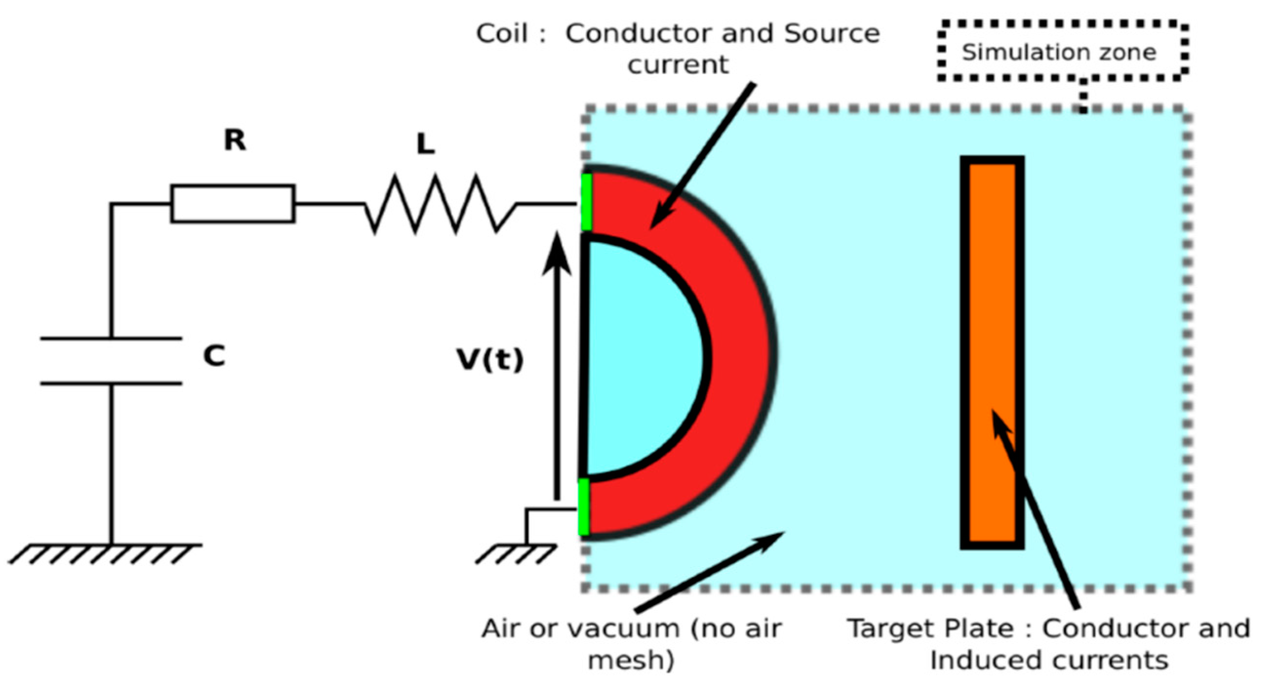
- A high pulse generator capable of generating an intense, time-varying current that will be the source of the time-varying magnetic field;
- A coil capable of producing the magnetic field due to the discharged current delivered by the generator;
- A conductive metal in the vicinity of the coil in which the magnetic field penetrates and induces currents, leading to the generation of large amounts of Laplace forces, causing its acceleration.
Objectives of Study
2. Materials and Methods
2.1. Materials
2.2. Equipment and Experimental Procedure
2.2.1. Pulse Generator
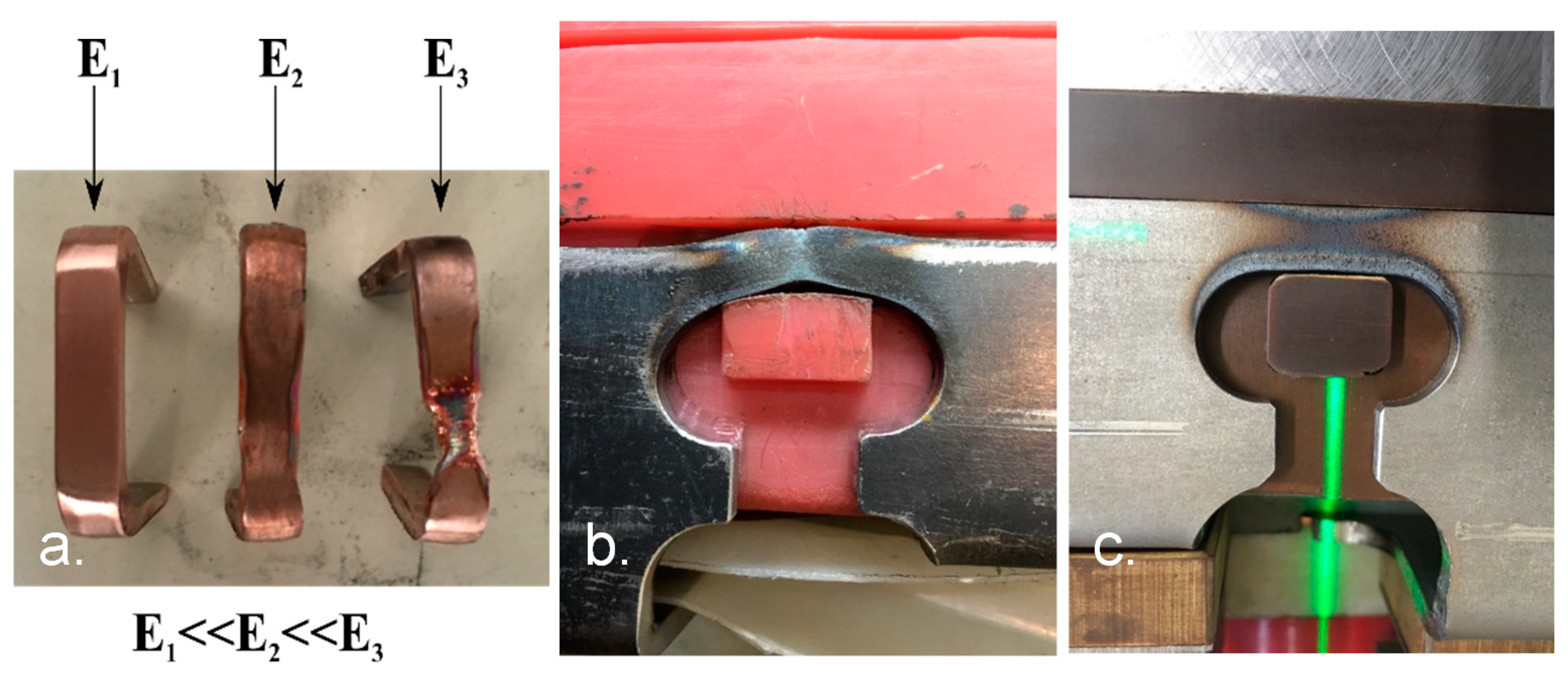
2.2.2. Coils
2.2.3. Discharge Energy and Discharge Current Relation
2.2.4. Experimental Procedure and Design
2.2.5. Welds Strength Evaluation
- Quasi-static at mm/s (with an Instron 5584 mechanical tensile machine, Norwood, MA, USA);
- Dynamic at 614 mm/s (with an MTS 819 hydraulic high-speed tensile machine, Eden Prairie, MN, USA);
- Fatigue under unidirectional conditions (, frequency of 20 Hz, with an MTS Electropulse E10000 machine, Eden Prairie, MN, USA).
2.2.6. Numerical Simulation
2.3. Materials Properties and Boundary Conditions
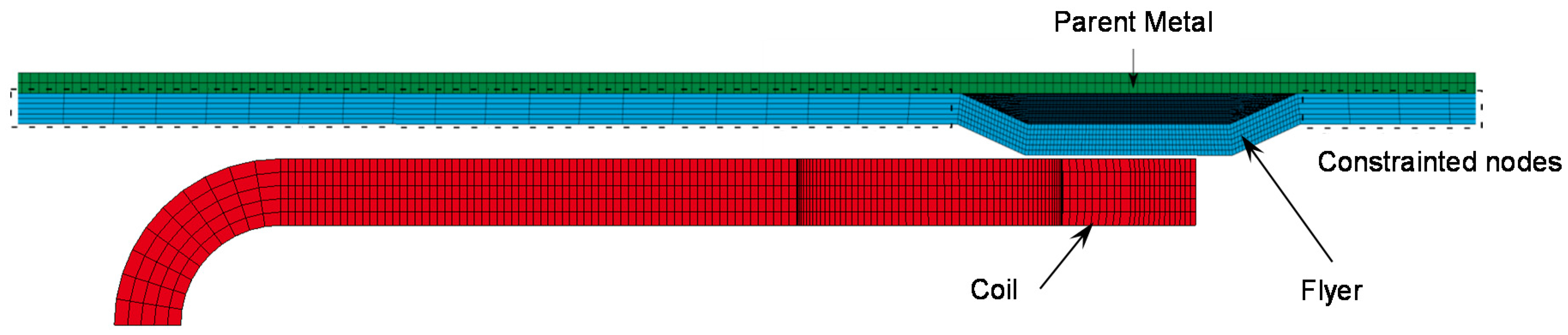
2.4. Mesh and Time Step
3. Results and Discussion
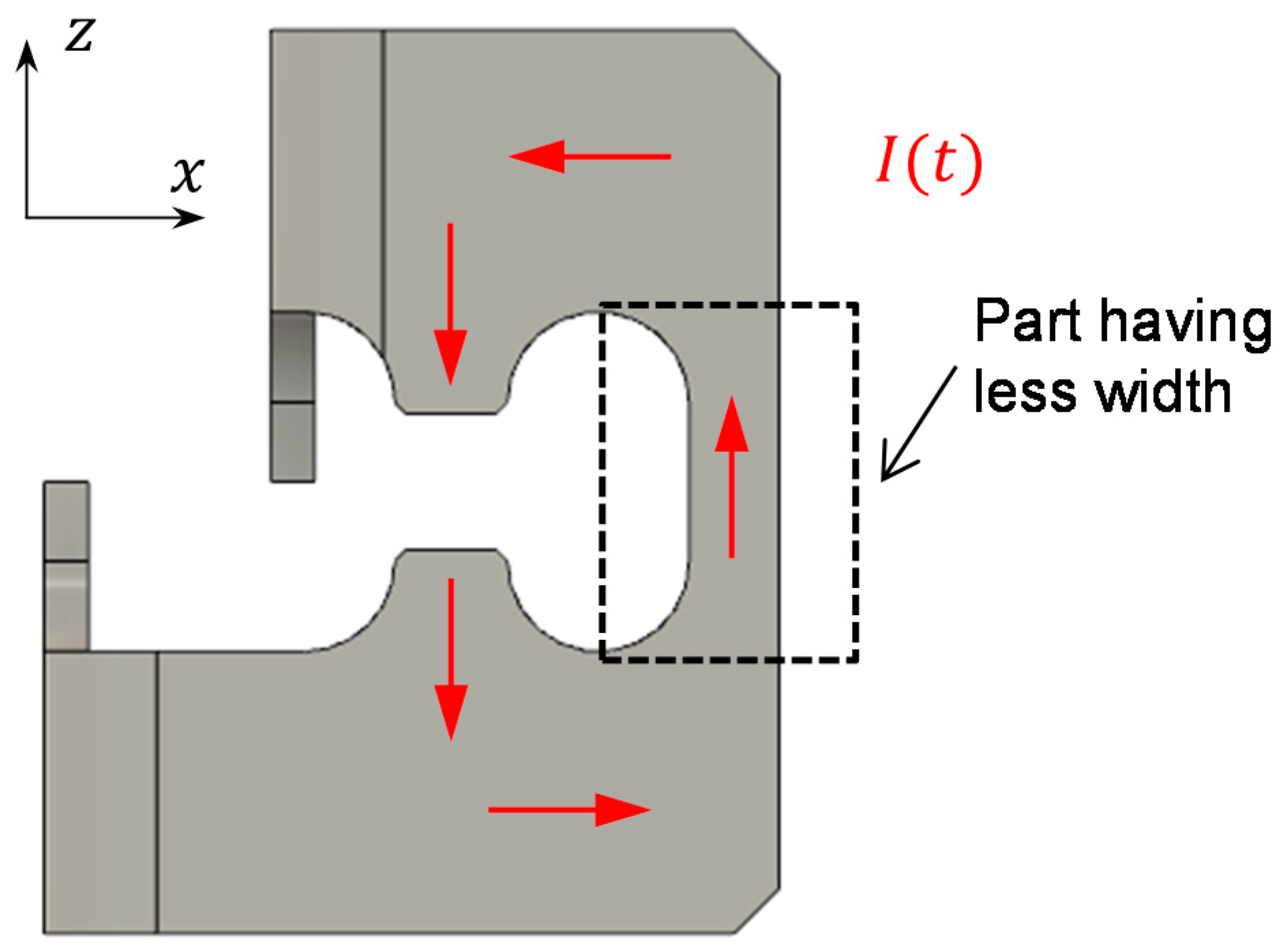
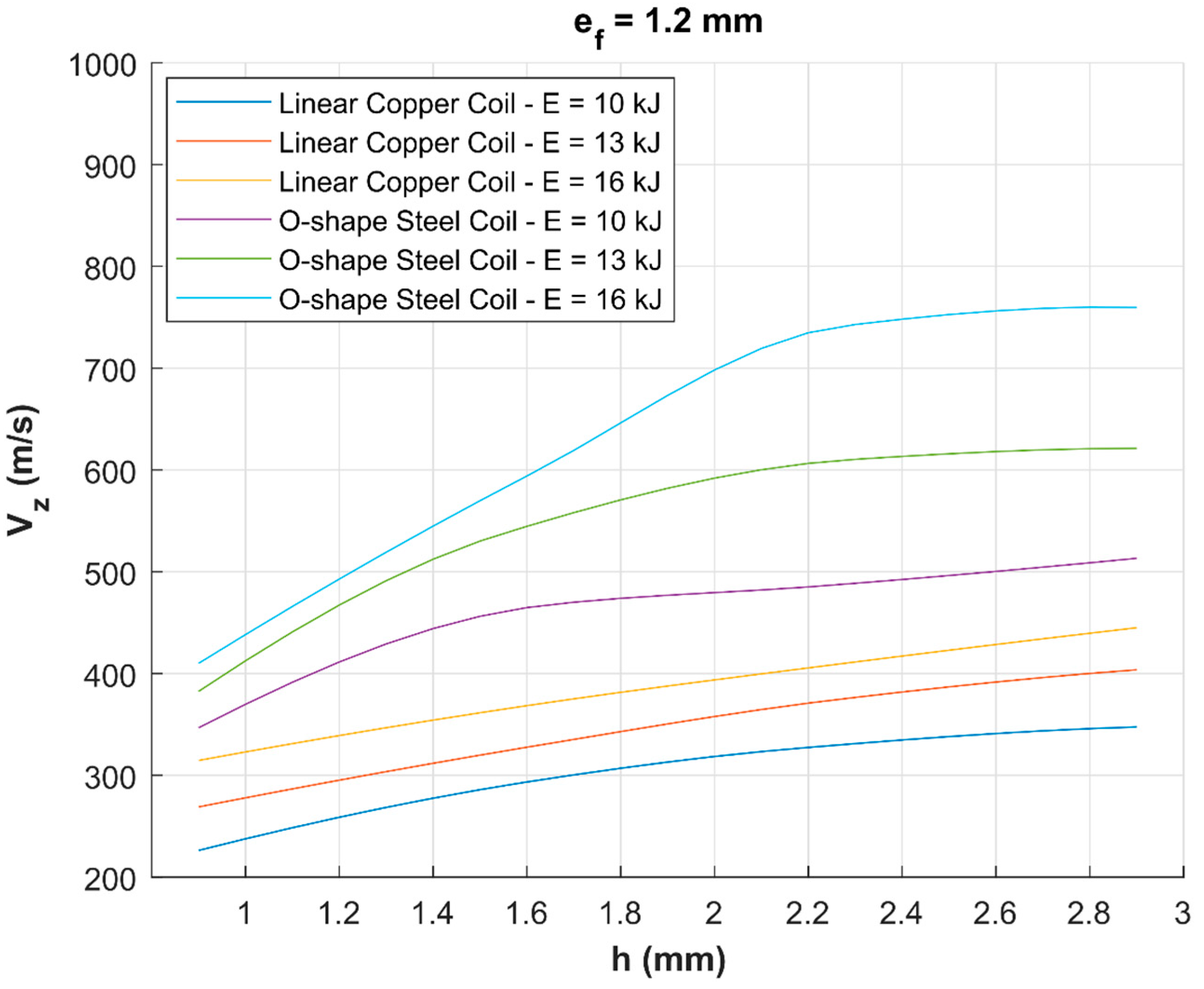
3.1. Numerical Comparison of Linear and O-Shape Coils Efficiencies
- Reducing the inductance of the coil to increase the peak currents (3);
- Putting more charge carriers on the flyer metal in movement to increase the induced currents magnitude and increasing, at the same time, the current density in the area where the material should be accelerated.
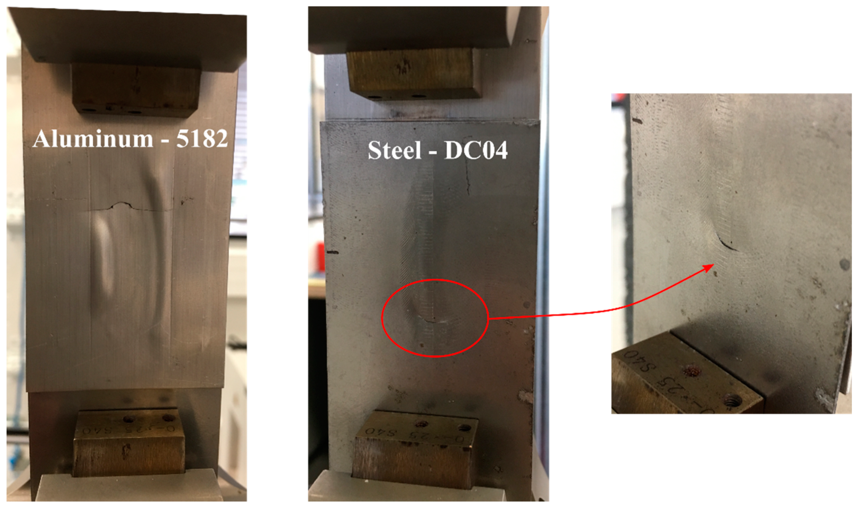
3.2. Experimental Validation
3.3. Mechanical Testing for the Welding Joints
- Aluminum 5182 ( mm) with steel DC04 ( mm) in MPSW configuration;
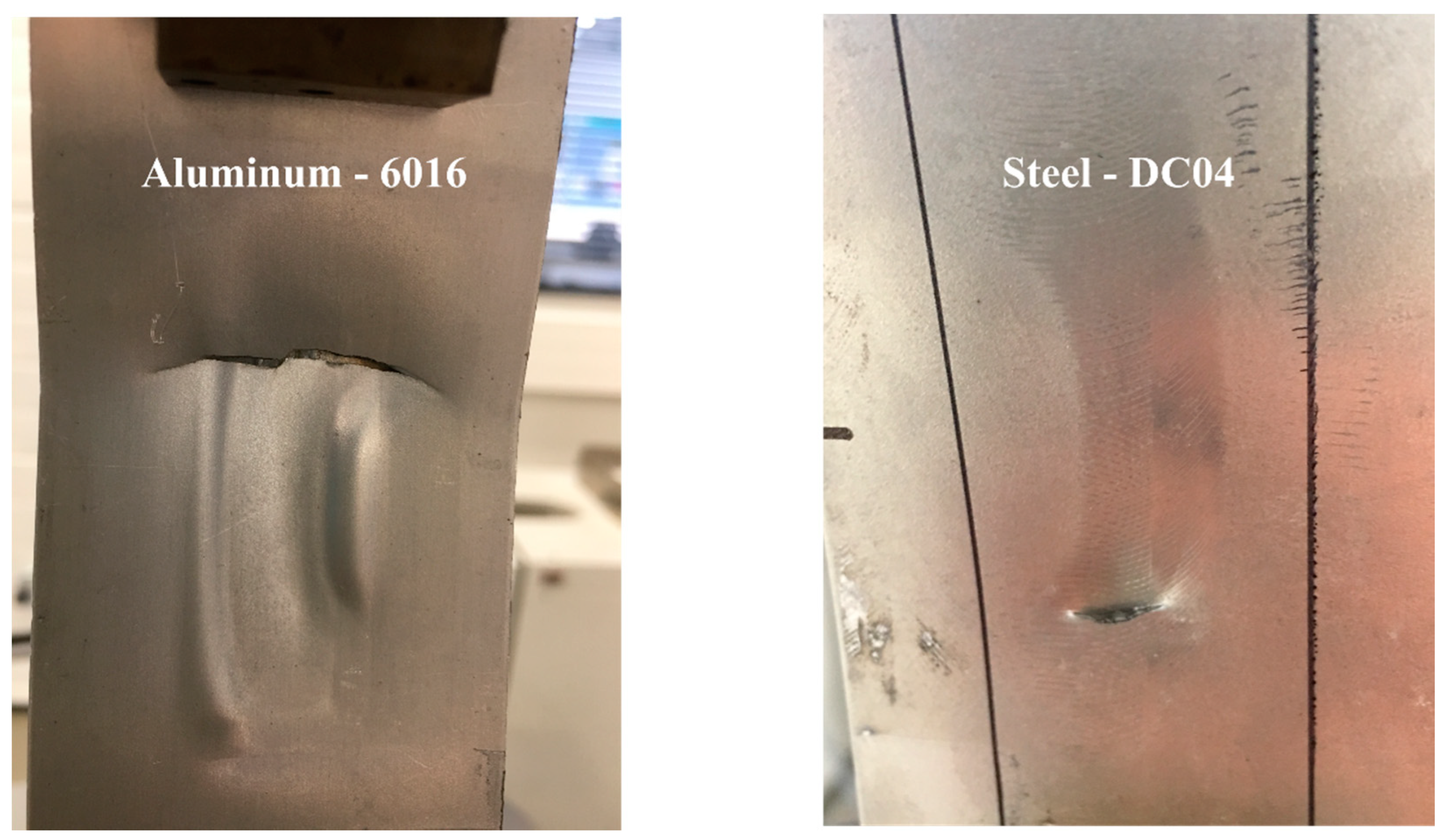
- Aluminum 6016 ( mm) with steel DC04 ( mm) in MPSW configuration;
- Aluminum 5182 ( mm) with steel DP450 ( mm) in MPSW configuration;
- Aluminum 6013-T4 ( mm) with steel DP1000 ( mm) in MPSW configuration;
- Aluminum 6013-T4 ( mm) with steel DP1000 ( mm) in MPW configuration.
- In MPW case: the welds showed quasi-static maximum loads between 7600 and 9500 N with displacements between 0.9 and 1.1 mm. The dynamic loads are between 13,700 and 14,600 N and the corresponding displacements are between 0.78 and 2.32 mm. The fatigue tests showed the number of cycles oscillating between 61,000 and 69,000;
- In the MPSW case: the welds showed quasi-static maximum loads in this case were between 7400 and 8400 N and the displacements were between 0.77 and 1.1mm. The dynamic loads attained were between 6300 and 9300 N and the displacements were between 2.75 and 5.2 mm. The fatigue tests showed a number of cycles between 30,000 and 32,000.
3.4. Inductor Life Cycle
- For a straight conductor, the life cycle is drastically reduced from 50 to 10 shots when the discharge energy is increased from 13 to 16 kJ;
- For O-shape conductors, 50 shots with a discharge energy of 18 kJ are observed. This is the highest limit, but with decreasing discharge energy, a much higher number of weld shots could be seen, but this was not evaluated in real terms.
4. Conclusions
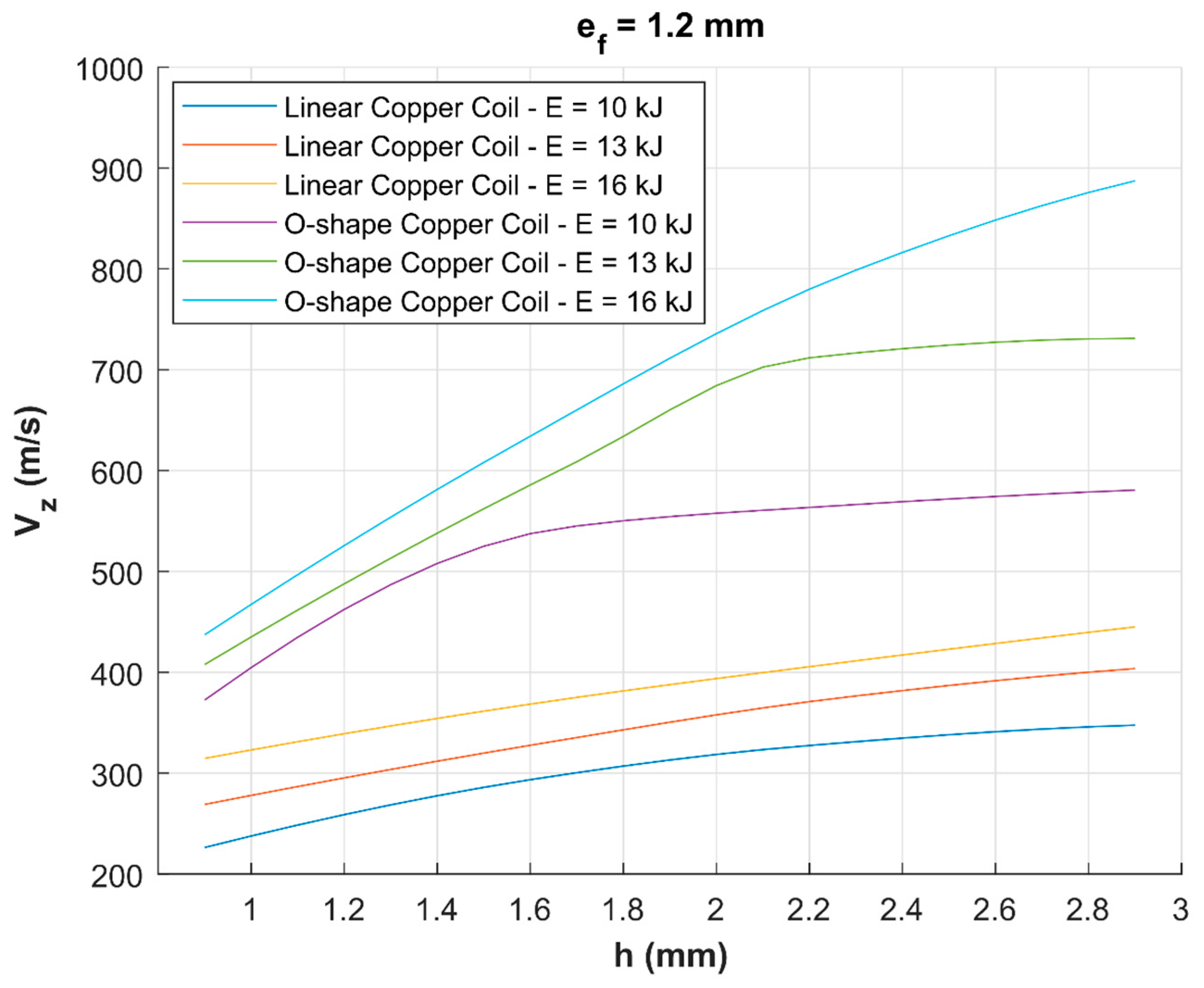
- Simulation suggests that O-shape coils have higher process efficiency when measured on impact velocity criterion compared to straight (I-shape) coils for identical process parameters (discharge Energy, flyer–parent gap). Irrespective of the coil material, O-shape coils produce higher impact velocities which are propitious to effective welding. The maximum impact velocities of 550 and 900 m/s are, respectively, estimated for straight and O-shape copper coils. Impact velocity increases with standoff linearly for straight coils, contrary to O-shape coils where a velocity plateau seems to shift towards higher standoffs with increasing discharge energy. For instance, the plateau onset point moves from 1.6 to 2.1 mm when discharge energy goes up from 10 to 13 kJ for copper O-shape coil. At 16 kJ, the plateau onset is not observed for copper O-shape coil within the standoff of 2.8 mm;
- Compared to steel, copper coil is estimated to generate superior impact velocities (900 m/s for copper O-shape coil vs. 710 m/s for steel O-shape coil at 16 kJ). Copper has a higher electrical conductivity—lower joule losses—but lower mechanical resistance than steel. Joule losses in steel coils end up with coil heating and would require cooling to maintain its stiffness in heavy duty applications as in automotive plants. The disadvantage with copper as coil material stem from the fact that coil gets heavy recoil pressure from the outgoing flyer sheet, which significantly reduces the life cycle of coil. Copper coils’ lifetime is reduced to a very few welds as the discharge energy increases;
- The life cycle of the O-shape coil is significantly higher than that of the straight coil and is subject to how the coil is mounted in its holding system. Though reasonable from a theoretical point of view, this requires further study for a quantitative measure;
- Higher impact velocities with O-shape coil, derived from numerical calculations, are indirectly validated by the possibility of welding additional couple sheets that were not straight coil at the tested discharge energies. For example, 1.4-mm thick 5182 was welded with 5754, DP450, and DC04; 2-mm thick 5182 with 5754, DP450, DC04, and, finally, 6013 with DP1000. As a general rule, thicker and materials with higher mechanical characteristics require superior discharge energies capable of providing higher impact velocities. When the generator has limited disposable energy, O-shape coil is a preferential choice for electromagnetic pulse welding;
- Quasi-static, dynamic shear tests along with fatigue test results on different sheet combinations attest a higher resistance of the spot welds as fracture occurred outside the welds, mostly around the corners of the welded spots where applied stresses are concentrated.
Author Contributions
Funding
Acknowledgments
Conflicts of Interest
References
- Messler, R.W. Joining of Materials and Structures: From Pragmatic Process to Enabling Technology; Butterworth-Heinemann: Burlington, MA, USA, 2004. [Google Scholar]
- Grote, K.-H.; Antonsson, E.K. Springer Handbook of Mechanical Engineering; Springer Science & Business Media: New York, NY, USA, 2009; Volume 10. [Google Scholar]
- Gould, J.E. Joining aluminum sheet in the automotive industry—A 30 year history. Weld. J. 2012, 91, 23–34. [Google Scholar]
- Solomon, H.D. Fundamentals of Weld Solidification. In Welding, Brazing and Soldering; ASM International: Novelty, OH, USA, 1993; pp. 45–54. ISBN 978-1-62708-173-3. [Google Scholar]
- Cieslak, M.J. Cracking Phenomena Associated With Welding. In Welding, Brazing and Soldering; ASM International: Novelty, OH, USA, 1993; pp. 88–96. ISBN 978-1-62708-173-3. [Google Scholar]
- Wagner, M.; Jahn, A.; Brenner, B. Innovative joining technologies for multi-material lightweight car body structures. In Proceedings of the International Automotive Body Congress (IABC), Dearborn, MI, USA, 29–30 October 2014; pp. 29–30. [Google Scholar]
- Kulkarni, N.; Mishra, R.S.; Yuan, W. Friction Stir Welding of Dissimilar Alloys and Materials; Butterworth-Heinemann: Oxford, UK, 2015. [Google Scholar]
- Matthew Gilloon, C.G. Remote laser welding boosts production of new Ford Mustang. Ind. Laser Solut. 2017, 32, 28–31. [Google Scholar]
- Agudo, L.; Eyidi, D.; Schmaranzer, C.H.; Arenholz, E.; Jank, N.; Bruckner, J.; Pyzalla, A.R. Intermetallic Fe x Al y-phases in a steel/Al-alloy fusion weld. J. Mater. Sci. 2007, 42, 4205–4214. [Google Scholar] [CrossRef]
- Rathod, M.; Kutsuna, M. Use of pulsed CO2 laser in laser roll bonding of A5052 aluminium alloy and low carbon steel. Weld. World 2006, 50, 28–36. [Google Scholar] [CrossRef]
- Van der Rest, C.; Jacques, P.J.; Simar, A. On the joining of steel and aluminium by means of a new friction melt bonding process. Scr. Mater. 2014, 77, 25–28. [Google Scholar] [CrossRef]
- Blazynski, T.Z. Explosive Welding, Forming and Compaction; Springer Science & Business Media: New Yok, NY, USA, 2012. [Google Scholar]
- Daehn, G.S.; Lippold, J.; Liu, D.; Taber, G.; Wang, H. Laser impact welding. In Proceedings of the 5th International Conference on High Speed Forming, Dortmund, Germany, 24–26 April 2012. [Google Scholar]
- Vivek, A.; Hansen, S.R.; Liu, B.C.; Daehn, G.S. Vaporizing foil actuator: A tool for collision welding. J. Mater. Process. Technol. 2013, 213, 2304–2311. [Google Scholar] [CrossRef]
- Manoharan, P.; Manogaran, A.P.; Priem, D.; Marya, S.; Racineux, G. State of the art of electromagnetic energy for welding and powder compaction. Weld. World 2013, 57, 867–878. [Google Scholar] [CrossRef]
- Bellmann, J.; Lueg-Althoff, J.; Schulze, S.; Gies, S.; Beyer, E.; Tekkaya, A.E. Measurement and analysis technologies for magnetic pulse welding: Established methods and new strategies. Adv. Manuf. 2016, 4, 322–339. [Google Scholar] [CrossRef]
- Shotri, R.; Racineux, G.; De, A. Magnetic pulse welding of metallic tubes—Experimental investigation and numerical modelling. Sci. Technol. Weld. Join. 2020, 25, 273–281. [Google Scholar] [CrossRef]
- Manogaran, A.P.; Manoharan, P.; Priem, D.; Marya, S.; Racineux, G. Magnetic pulse spot welding of bimetals. J. Mater. Process. Technol. 2014, 214, 1236–1244. [Google Scholar] [CrossRef]
- Manogaran, A.P. Développement du Procédé de Soudage par Point par Implusion Magnétique: Assemblage Hétérogène Al/Fe. Doctoral Dissertation, Ecole centrale de Nantes, Nantes, France, 2013. [Google Scholar]
- Marya, M.; Marya, S. Interfacial microstructures and temperatures in aluminium—Copper electromagnetic pulse welds. Sci. Technol. Weld. Join. 2004, 9, 541–547. [Google Scholar] [CrossRef]
- Aizawa, T. Magnetic Pulse Welding of Al/Cu Sheets Using 8-Turn Flat Coil. J. Light Met. Weld. 2020, 58, 97s–101s. [Google Scholar]
- Avettand-Fènoël, M.-N.; Khalil, C.; Taillard, R.; Racineux, G. Effect of steel galvanization on the microstructure and mechanical performances of planar magnetic pulse welds of aluminum and steel. Metall. Mater. Trans. A 2018, 49, 2721–2738. [Google Scholar] [CrossRef]
- Mallick, P.K. Materials, Design and Manufacturing for Lightweight Vehicles; Elsevier: Amsterdam, The Netherlands, 2010. [Google Scholar]
- Johnson, G.R.; Cook, W.H. A constitutive model and data for metals subjected to large strains, high strain rates and high temperatures. In Proceedings of the 7th International Symposium on Ballistics, The Hague, The Netherlands, 19–21 April 1983; Volume 21, pp. 541–547. [Google Scholar]
- Seidt, J.D.; Gilat, A.; Klein, J.A.; Leach, J.R. High strain rate, high temperature constitutive and failure models for EOD impact scenarios. In Proceedings of the SEM Annual Conference & Exposition on Experimental and Applied Mechanics, Springfield, MA, USA, 3–6 June 2007; p. 15. [Google Scholar]
- Smerd, R.; Winkler, S.; Salisbury, C.; Worswick, M.; Lloyd, D.; Finn, M. High strain rate tensile testing of automotive aluminum alloy sheet. Int. J. Impact Eng. 2005, 32, 541–560. [Google Scholar] [CrossRef]
- Verleysen, P.; Peirs, J.; Degrieck, J. Experimental study of dynamic fracture in Ti6A14V. In Proceedings of the 4th International Conference on Impact Loading of Lightweight Structures (ICILLS 2014), Cape Town, South Africa, 12–16 January 2014. [Google Scholar]
- Burgess, T.J. Electrical resistivity model of metals. In Proceedings of the 4th International Conference on Megagauss Magnetic-Field Generation and Related Topics, Santa Fe, NM, USA, 14–17 July 1986. [Google Scholar]
- Hallquist, J.O. LS-DYNA Theory Manual; Livermore Soft-Ware Technology Corporation: Livermore, CA, USA, 2006. [Google Scholar]
- Mamutov, A.V.; Golovashchenko, S.F.; Mamutov, V.S.; Bonnen, J.J. Modeling of electrohydraulic forming of sheet metal parts. J. Mater. Process. Technol. 2015, 219, 84–100. [Google Scholar] [CrossRef]


| Si max | Fe max | Cu max | Mn max | Mg max | Cr max | Zn max | Ti max | Other max | |
|---|---|---|---|---|---|---|---|---|---|
| 1050 | 0.25 | 0.40 | 0.05 | 0.05 | 0.05 | - | 0.07 | 0.05 | 0.03 |
| 5182 | 0.20 | 0.35 | 0.15 | 0.50 | 4.0–5.00 | 0.10 | 0.25 | 0.10 | 0.15 |
| 5754 | 0.40 | 0.40 | 0.10 | 0.50 | 2.6–3.6 | 0.30 | 0.20 | 0.15 | - |
| 6013 | 0.78 | 0.28 | 0.97 | 0.40 | 1.02 | 0.06 | 0.10 | 0.05 | 0.15 |
| 6016 | 0.5–1.5 | 0.50 | 0.20 | 0.20 | 0.25–0.70 | 0.10 | 0.20 | 0.15 | 0.15 |
| C max | Mn max | Si max | P max | S max | Al max | |
|---|---|---|---|---|---|---|
| DC04 | 0.08 | 0.40 | 0.10 | 0.025 | 0.025 | 0.020 |
| C max | Mn max | Si max | P max | S max | Al max | Ti + Nb max | V max | Cr max | Mo max | B max | N max | Ni max | Nb max | |
|---|---|---|---|---|---|---|---|---|---|---|---|---|---|---|
| DP450 | 0.10 | 0.16 | 0.4 | 0.04 | 0.015 | 0.015–0.08 | 0.05 | 0.01 | 0.8 | 0.3 | 0.005 | 0.008 | - | - |
| DP1000 | 0.139 | 1.50 | 0.21 | 0.009 | 0.002 | 0.046 | - | 0.01 | 0.02 | - | 0.0002 | 0.003 | 0.03 | 0.015 |
| YS (MPa) | UTS (MPa) | A % ISO 20 × 80 | |
|---|---|---|---|
| DC04 (e ≤ 1.47 mm) | 160–200 | 280–340 | 37 |
| DP450 | 290–340 | 460–560 | 27 |
| DP1000 | 787 | 1059 | 8.5 |
| YS (MPa) | UTS (MPa) | A % ISO 20 × 80 | |
|---|---|---|---|
| 1050-H14 | 85 | 105 | 4 |
| 5754-H111 (e ≤ 1.5 mm) | 90–130 | 200–240 | 21 |
| 5182 (e ≤ 1.5 mm) | 120–160 | 260–310 | 23 |
| 6013-T4 | 174 | 310 | 26 |
| 6016-T4 | 110–150 | 220–270 | 23 |
| Coil | Alloy | A (MPa) | B (MPa) | n | C | m |
|---|---|---|---|---|---|---|
| Linear Coil | OFHC | 90 | 292 | 0.31 | 0.025 | 1.09 |
| O-Shape Coil | OFHC | 90 | 292 | 0.31 | 0.025 | 1.09 |
| ASTM A36 | 286.1 | 500.1 | 0.2282 | 0.022 | 0.917 | |
| Flyers | 5754 | 67.456 | 471.242 | 0.424 | 0.003 | 2.519 |
| 5182 | 106.737 | 569.120 | 0.485 | −0.001 | 3.261 | |
| Parent | DC04 | 162 | 598 | 0.6 | 2.623 | 0.009 |
| Coil | Alloy | Thermal Conductivity (W/mk) | Specific Heat Capacity (J/kgK) |
|---|---|---|---|
| Linear Coil | OFHC | 386 | 383 |
| O-Shape Coil | OFHC | 386 | 383 |
| ASTM A36 | 50 | 450 | |
| Flyers | 5754 | 130 | 897 |
| 5182 | 123 | 902 | |
| Parent | DC04 | 52 | 470 |
| Coil | Alloy | %IACS (International Annealed Copper Standard) | S/m |
|---|---|---|---|
| Linear Coil | OFHC | 100 | |
| O-Shape Coil | OFHC | 100 | |
| ASTM A36 | 12 | ||
| Flyers | 5754 | 33 | |
| 5182 | 28 | ||
| Parent | DC04 | 13 |
| Parameter | Cu | Al |
|---|---|---|
| (/g) | 0.112 | 0.370 |
| 2 | 2.13 | |
| 0.113 | 0.223 | |
| 1.145 | 1.210 |
| Parent Flyer | 5754 | 5182 | 6016 | DP450 | DP1000 | DC04 | ||||||
|---|---|---|---|---|---|---|---|---|---|---|---|---|
| L | O | L | O | L | O | L | O | L | O | L | O | |
| 5754 (0.5 mm) | ✓ | ✓ | ✓ | ✓ | ✓ | ✓ | ✓ | ✓ | ✓ | ✓ | ✓ | ✓ |
| 5182 (1 mm) | ✓ | ✓ | - | - | - | - | ✓ | ✓ | - | - | ✓ | ✓ |
| 5182 (1.2 mm) | ✓ | ✓ | - | - | - | - | ✓ | ✓ | - | - | ✓ | ✓ |
| 5182 (1.4 mm) | ✗ | ✓ | - | - | - | - | ✗ | ✓ | - | - | ✗ | ✓ |
| 5182 (2 mm) | ✗ | ✓ | - | - | - | - | ✗ | ✓ | - | - | ✗ | ✓ |
| 6013 (1.4 mm) | - | - | - | - | - | - | - | - | ✗ | ✓ | ✗ | ✓ |
| 6016 (1 mm) | ✓ | ✓ | - | - | - | - | - | - | - | - | ✓ | ✓ |
| Materials (Flyer/Target) | Welding Configuration | Fmax—Quasi-Static Lap-Shear Test | |||||||
| Average | Average | Specimen 1 | Specimen 2 | Specimen 3 | |||||
(N) | (mm) | (N) | (mm) | (N) | (mm) | (N) | (mm) | ||
| 5182/DC04 | MPSW | 6500 | 1.63 | 6250 | 1.56 | 6500 | 1.7 | 6750 | 1.62 |
| 5182/DP450 | MPSW | 9400 | 1.64 | 10,000 | 1.88 | 9000 | 1.32 | 9200 | 1.73 |
| 6016/DC04 | MPSW | 8433 | 2.15 | 8500 | 2.15 | 8700 | 2.3 | 8100 | 2 |
| 6013/DP1000 | MPSW | 7800 | 0.98 | 8400 | 1.1 | 7600 | 1.06 | 7400 | 0.77 |
| 6013/DP1000 | MPW | 8767 | 0.98 | 9500 | 1.1 | 9200 | 0.95 | 7600 | 0.9 |
| Materials (Flyer/Target) | Welding Configuration | Fmax—Dynamic Lap-Shear Test (0.614 m/s) | |||||||
| Average | Average | Specimen 1 | Specimen 2 | Specimen 3 | |||||
(N) | (mm) | (N) | (mm) | (N) | (mm) | (N) | (mm) | ||
| 5182/DC04 | MPSW | 8067 | 1.46 | 8300 | 1.48 | 7900 | 1.53 | 8000 | 1.38 |
| 5182/DP450 | MPSW | 7033 | 1.88 | 8500 | 2.9 | 6500 | 1.37 | 6100 | 1.36 |
| 6016/DC04 | MPSW | >9000 | >9000 | >9000 | >9000 | ||||
| 6013/DP1000 | MPSW | 7667 | 3.85 | 9300 | 2.75 | 7400 | 3.6 | 6300 | 5.2 |
| 6013/DP1000 | MPW | 14,233 | 1.7 | 14,600 | 2.32 | 14,400 | 1.3 | 13,700 | 0.78 |
| Materials (Flyer/Target) | Welding Configuration | (kN) | Number of Cycles | |||
| Average | Specimen 1 | Specimen 2 | Specimen 3 | |||
| 5182/DC04 | MPSW | 4 | 26,333 | 26,000 | 28,000 | 25,000 |
| 5182/DP450 | MPSW | 5 | 22,333 | 21,000 | 24,000 | 22,000 |
| 6016/DC04 | MPSW | 4.4 | 43,000 | 44,000 | 42,000 | 43,000 |
| 6013/DP1000 | MPSW | 4.4 | 31,000 | 32,000 | 30,000 | 31,000 |
| 6013/DP1000 | MPW | 5 | 64,333 | 61,000 | 69,000 | 63,000 |
| Data Analysis | |||||||||||||||||
|---|---|---|---|---|---|---|---|---|---|---|---|---|---|---|---|---|---|
| Inductor # | Shots Per Energy | Total Shots | Total Cumulative Energy (kJ) | Average Energy Usage | |||||||||||||
| 5 | 6 | 7 | 8 | 9 | 10 | 11 | 12 | 13 | 14 | 15 | 16 | 17 | 18 | ||||
| 9 | 0 | 0 | 0 | 0 | 0 | 0 | 0 | 0 | 0 | 0 | 0 | 3 | 0 | 0 | 3 | 48 | 16 |
| 8 | 0 | 0 | 0 | 0 | 0 | 3 | 0 | 0 | 3 | 0 | 0 | 1 | 0 | 0 | 7 | 85 | 12 |
| 7 | 0 | 0 | 0 | 0 | 0 | 3 | 0 | 0 | 3 | 0 | 0 | 3 | 0 | 0 | 9 | 117 | 13 |
| 3 | 0 | 0 | 0 | 0 | 0 | 3 | 0 | 0 | 2 | 0 | 0 | 6 | 0 | 0 | 11 | 152 | 14 |
| 4 | 0 | 0 | 0 | 0 | 0 | 4 | 0 | 0 | 3 | 0 | 0 | 4 | 0 | 0 | 11 | 143 | 13 |
| 6 | 0 | 0 | 0 | 0 | 0 | 3 | 0 | 0 | 5 | 1 | 0 | 3 | 0 | 0 | 12 | 157 | 13 |
| 5 | 0 | 1 | 3 | 3 | 5 | 2 | 1 | 0 | 1 | 0 | 0 | 3 | 0 | 0 | 19 | 188 | 10 |
| 14 | 0 | 0 | 0 | 0 | 0 | 3 | 0 | 0 | 5 | 0 | 0 | 25 | 0 | 0 | 33 | 495 | 15 |
| 10 | 0 | 0 | 0 | 1 | 0 | 6 | 0 | 0 | 10 | 3 | 0 | 14 | 0 | 0 | 34 | 464 | 14 |
| 13 | 0 | 0 | 0 | 0 | 0 | 7 | 0 | 8 | 4 | 7 | 0 | 16 | 0 | 1 | 43 | 590 | 14 |
| 12 | 0 | 0 | 0 | 0 | 0 | 15 | 0 | 0 | 16 | 0 | 0 | 16 | 0 | 0 | 47 | 614 | 13 |
| 2 | 5 | 11 | 10 | 8 | 6 | 6 | 0 | 0 | 7 | 0 | 0 | 0 | 0 | 0 | 53 | 430 | 8 |
© 2020 by the authors. Licensee MDPI, Basel, Switzerland. This article is an open access article distributed under the terms and conditions of the Creative Commons Attribution (CC BY) license (http://creativecommons.org/licenses/by/4.0/).
Share and Cite
Khalil, C.; Marya, S.; Racineux, G. Magnetic Pulse Welding and Spot Welding with Improved Coil Efficiency—Application for Dissimilar Welding of Automotive Metal Alloys. J. Manuf. Mater. Process. 2020, 4, 69. https://doi.org/10.3390/jmmp4030069
Khalil C, Marya S, Racineux G. Magnetic Pulse Welding and Spot Welding with Improved Coil Efficiency—Application for Dissimilar Welding of Automotive Metal Alloys. Journal of Manufacturing and Materials Processing. 2020; 4(3):69. https://doi.org/10.3390/jmmp4030069
Chicago/Turabian StyleKhalil, Chady, Surendar Marya, and Guillaume Racineux. 2020. "Magnetic Pulse Welding and Spot Welding with Improved Coil Efficiency—Application for Dissimilar Welding of Automotive Metal Alloys" Journal of Manufacturing and Materials Processing 4, no. 3: 69. https://doi.org/10.3390/jmmp4030069
APA StyleKhalil, C., Marya, S., & Racineux, G. (2020). Magnetic Pulse Welding and Spot Welding with Improved Coil Efficiency—Application for Dissimilar Welding of Automotive Metal Alloys. Journal of Manufacturing and Materials Processing, 4(3), 69. https://doi.org/10.3390/jmmp4030069