Abstract
Producing complex sheet metal components in fewer process steps motivated the development of the innovative forming process called sheet-bulk metal forming (SBMF). In this process, sheet metal forming and bulk-metal forming are combined to create a unique forming process in which a component with external and internal gearing is produced in three production steps. However, the high degrees of deformation that occur using high-strength steels and the number of different process steps result in high process forces, strongly limiting the service life of tools. To reduce the forming force during SBMF processes, tool and process modifications were investigated. Therefore, plane-strain compression tests were conducted to examine the influence of a CrAlN PVD coating and tailored surfaces produced by high-feed milling (HF) of tool-active elements on the material flow of the specimens. In addition to the tool-sided modifications, the influence of an oscillation overlay during the forming process was investigated. Based on the results of the compression tests, the surfaces of the active tool elements of the SBMF process were modified in order to transfer the basic experimental results to the production of a functional component. The friction is thus adapted locally in the SBMF process.
1. Introduction
A newly developed class of forming processes called sheet-bulk metal forming (SBMF) combines the advantages of bulk forming operations on sheet metal workpieces [1]. Salfeld et al. attribute great potential to the new technology, which offers the options of work hardening and near-net-shape production, in terms of reducing process time and production costs [2]. Due partially to the high degrees of deformation achieved in the SBMF, very strong process forces result. In addition, the tribological contact situations between the forming tools and the sheet metal workpieces have a strong impact due to the relatively large contact surfaces. Both factors can limit the potential of the new process technology if they are not sufficiently considered during the process design.
According to the literature, experiments with superimposed oscillation forming have been conducted since the 1950s. The focus of these investigations, such as those of Nevill et al. (1957) [3] or Blaha and Langenecker (1959) [4] was especially on superimposed oscillation forming in the ultrasonic frequency range. Izumi et al. [5], as well as Begherzadeh and Abrinia [6], observed a reduction in the yield stress because of softening effects due to superimposed oscillation forming. As an explanation for the oscillation-based reduction of average forming force, two main approaches can be identified in literature [7]. One approach explains the forming force reduction with volume-related effects. Izumi et al. postulates that an oscillation overlay leads to an accelerated dislocation movement, causing a temporary softening of the material [5]. Kirchner et al. attributed the reduction of the mean stress during superimposed oscillation forming to the elastic relaxation of the samples during stress release [8]. Another approach explains the forming force reduction with surface-related effects. Koch et al. explained that an oscillation superimposition causes a softening effect between the surfaces of tools and samples, which leads to a reduction of friction and thus of forming force [9]. To extend the process limits of the new technology SBMF and to create an application-related investigation environment, a multistage SBMF process, in which a component with an external and an internal gearing is produced in the three process steps from a sheet metal ronde, was developed [10]. In this process, superimposed oscillation forming is used in the second operation step for the forming of the internal gearing. This process modification led to positive effects in terms of improved mold filling and reduced forming forces [11].
In addition to superimposed oscillation forming, SBMF processes can also be enhanced by adjusting the tools’ functional surfaces. This targeted design of surface properties for influencing the process can be summarized under the term tailored surfaces [12]. It has already been shown that functional surface structures as well as additional coating systems can improve the mold filling of filigree secondary form elements by adjusting the tribological contact conditions between tool and workpiece [13,14]. By specifically modifying the contact conditions with the use of tailored surfaces, the material flow in forming processes can be adjusted to enhance the molding [12,15,16]. Furthermore, the application of additional coating systems can have a positive effect not only on friction but also on the wear behavior of the mold [14,17,18]. However, the influence of tailored surfaces with respect to high feed surface structures and wear-resistant PVD-coatings in combination with a superimposed oscillation process control on the forming process has not been fully understood. For this reason, modified tool surfaces were evaluated in a superimposed oscillation forming process to evaluate the benefits of surface modifications with respect to forming processes. Since both a superimposed oscillation and the installation of coated and structured tool surfaces lead to an extension of the forming limits, their combined investigation is of high interest. Especially in industrial applications, these technologies provide the potential to produce geometries that cannot be achieved with conventional methods of forming technology. In particular, the focus is on filigree functional elements whose production requires high local forming degrees.
2. Materials and Methods
2.1. Materials
The heat-treated high-speed steel AISI M2 was used with a hardness of 60 HRC. This steel has a very high adhesive and abrasive wear resistance with high toughness and compressive strength. For the sample material, the ferritic deep-drawn steel DC04 and the dual-phase steel DP600 were selected. Steels with significantly different mechanical properties were specifically used to investigate the influence of structured tool surfaces and a superimposed oscillation forming process independent of material-related influences. Compared to DC04, DP600 is characterized by high tensile strength and good cold formability. Therefore, DC04 has a tensile strength of 270–350 MPa, while DP600 has a tensile strength of 580–670 Mpa.
2.2. Forming Process
The multistage SBMF process enables the manufacturing of a complex functional symmetrical component with internal and external gearing made out of flat sheet. The entire process chain is illustrated in Figure 1. It consists of three stages with six manufacturing operations. The first stage combines deep drawing without blank holder, compressing and shear cutting. After the first stage, a semi-finished symmetrical part with external gearing and a centric hole is present. In the next process stage, collar drawing and ironing are conducted simultaneously to form the internal gears. Due to the incomplete mould filling of the internal gearing in the second stage, it is calibrated in the third stage.
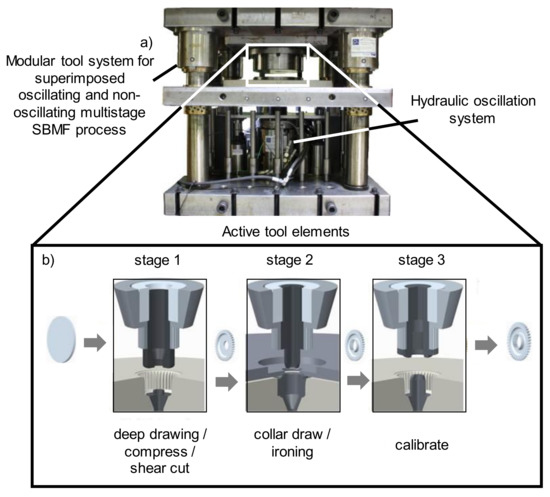
Figure 1.
(a) Modular tool system for new multistage SBMF process, (b) Active tool elements of single stages of the SBMF process [4].
In order to reduce the process development time, FE simulations of single stages were conducted and analysed [11]. To optimize the material flow and to reduce forming force in the process, tool parameters were modified on the basis of plane-strain compression tests. The coated and structured tools for the first stage of the SBMF process were used to conduct forming experiments with tailored surfaces.
2.3. High-Feed Milling of Quasi-Deterministic Surface Structures
Quasi-deterministic functional surface structures were applied to the forming tools by a high-feed milling process [19]. In general, high-feed milling is used for rough and hard machining in order to process large quantities of material in a short time. Compared to conventional milling processes, high feeds per tooth fz and low depth of cuts ap are used, which makes the process ideal for efficiently structuring even large surface areas [20]. By adapting process parameters like feed per tooth fz, lead angle α, width of cut ae and process strategy, a variety of surface structures with specific tribological characteristics can be manufactured [19]. Depending on the tribological properties, surface structures can affect the local friction characteristics, which offers new potential regarding the control of material flow [12,21]. The presented surfaces were manufactured on a DMG HSC 75 five-axis milling machine using a conventional FRAISA high-feed end mills. Two different surface structures were applied by varying the process strategy while keeping the machining parameters constant; see Figure 2.
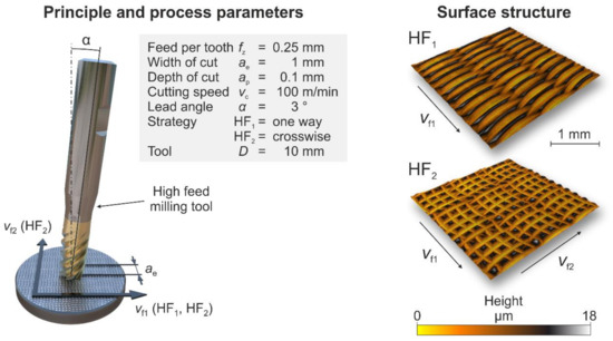
Figure 2.
Process kinematics of high-feed structuring (left) and topography of surface structure of HF1 and HF2 (right).
Thus, based on its topography structure, HF1 should lead to an anisotropic material flow, as it is machined in a process with parallel tool paths. The resulting structural elements are oriented orthogonally to the feed direction. Structured HF2 should be more isotropic in terms of surface characteristics, which is achieved by milling crosswise in a second step [19]. To determine the impact on forming operations, both surface structures were tested in a plane-strain compression test. As depicted in Figure 3, the anisotropic surface structure HF1 was applied in different orientations to the relevant functional surfaces of the multistage SBMF forming tool.
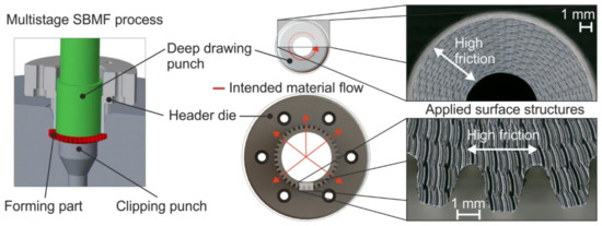
Figure 3.
Multistage SBMF process (left) and modified functional surface HF1 on deep drawing punch (top right) and header die (bottom right).
The surface structure HF1 has an anisotropic topography, which significantly determines the friction behavior. Therefore, the orientation was taken into account when applying the structure on the SBMF tools, as explained in the following. The systematic arrangement of the surface structures was based on the aim of reducing the necessary process force, which is required for a complete shaping of the secondary mold elements. This should be achieved by favoring the material flow in the direction of the outer tooth cavities. In order to inhibit the material flow in radial direction at the deep drawing punch and to retain a larger material volume, the structure HF1 was applied in a tangential direction. In contrast, the structure HF1 was manufactured with a radial orientation on the header die. This should offer high friction in the radial direction for the deep drawing punch and high friction in the tangential direction for the header die [19]. As a result, the material flow towards the secondary mold elements should be enhanced in order to achieve a higher degree of shaping.
2.4. PVD-Coating Technology
Subsequent to the structuring process, the surfaces of the tools were coated with a 3-µm thick CrAlN film to protect the small functional elements of the structures. The deposition was conducted in an industrial magnetron sputtering device CC800/9 Custom (CemeCon AG, Germany). Prior to the actual coating process, a sequence of cleaning, heating and etching processes was performed to ensure good adhesion of the CrAlN coating. As target material, two AlCr20 targets were used in a nitrogen-controlled atmosphere at a constant pressure of 500 mPa. As noble gas, a mixture of argon (120 sccm) and krypton (80 sccm) in combination with a bias voltage of −120 V applied at the substrate were chosen as reported in [22,23]. For the near net-shaped coating of the surfaces, a thickness of approximately 3 µm was selected, having a hardness of H = 31.67 ± 1.48 GPa and a Young’s Modulus of E = 372.6 ± 10.5 GPa determined by nanoindentation.
2.5. Plane-Strain Compression Test with and without Oscillation Overlay
The plane-strain compression test is used to determine true stress/true strain curves at higher strain values. In this test, the material flows equally on both sides of the punches. The loaded surface area remains constant. The direct influence of the surface contours on the material flow can thus be examined almost without interference [24]. The effect on the forming force as a function of the surface contours is of primary importance here. Therefore, this test is a suitable method to analyse the influence of tool coating and tool structuring on the forming behaviour of metallic materials. To introduce superimposed oscillation in a plane-strain compression test, a new tool system was developed as presented in Figure 4.
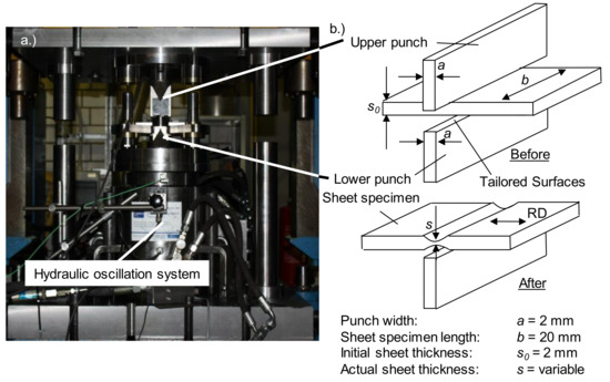
Figure 4.
(a) Tool system and (b) specimen for plane-strain compression test.
This tool system consists of two main components, a plane-strain compression tool and a hydraulic oscillation unit developed within the scope of the TCRC73. The hydraulic oscillation unit can generate an excitation frequency spectrum in a range of 0 Hz ≤ f ≤ 600 Hz at an amplitude of A = 10 μm to A = 50 μm. The displacement stroke of the sheet specimen was measured by a laser displacement sensor. Forming force absorption during the experiment was recorded by a load cell placed between the plane-strain compression tool and the hydraulic oscillation system. The force-path curves during forming are detected with the laser sensor and the load cell. At the beginning of the experiment, the sheet specimen is positioned between the dies. The hydraulic oscillation system and thus the tool subassembly, including the lower die, oscillates. The upper die compresses the sheet specimen up to the desired specimen height superimposed oscillation.
Samples of 2-mm thick mild steel DC04 and dual-phase steel DP600 were examined in the plane-strain compression test; see Figure 4b. The upper and lower dies are made of HS6-5-2C with a hardness of 60 ± 2 HRC, comparable to the SBMF experimental setup. The active surfaces of the punches are applied with HF1 and HF2 structures and coatings (see Figure 4). Furthermore, unstructured and uncoated punches are used. The tests were conducted both with and without the aid of the lubricant Beruforge 152DL. Furthermore, oscillating and non-oscillating experiments were conducted at room temperature, and the upset speed was kept constant at 1 mm/s. All superimposed oscillation experiments were conducted with a frequency of f = 200 Hz and an amplitude of A = 20 μm. Five experiments were conducted for each experimental parameter. The strain rate is set constant at 1.15 s−1.
3. Results and Discussion
3.1. Plane-Strain Compression Tests
The non-superimposed oscillation plane-strain compression tests were evaluated to consider the influence of the coating and surface structuring of the tools’ functional surfaces. The results shown in Figure 5 indicate that the HF1 structure leads to a significant reduction in forming force compared to unstructured and uncoated plane-strain compression test stamps. The reduction of the forming force was in the range of 17% from 28 ± 1 kN to 23 ± 1 kN for the DC04 specimens and in the range of about 7.5% from 38 ± 1 kN to 35 ± 1 kN for the DP600 specimens. The difference in the forming behavior of the materials could be explained by the different flow stresses of the two specimens. Using the HF2 structure, a slight reduction in process forces could be achieved, which was, however, lower compared to the previous results. This disparate process behavior was attributed to the varying topography of both surface structures. Based on the results and further investigations, it can be assumed that the material flow along the crests of the structure HF1 is enhanced [15,19]. The structure HF1 was applied on the active parts of the tools, leading to an improved material flow out of the compression zone. As can be seen from the results in Figure 5, a significant reduction in process forces could be achieved. In contrast, due to a different topography, structure HF2 has no preferential direction over the structure crests. This led to an increase in roughness in the material flow direction and thus also to an increase in process forces compared to the HF1 structure, as can be seen in particular in the tests with the DC04 material. Nevertheless, the forming force is lower with the HF2-structured stamps than it is with the unstructured stamps. This can be explained with a lower contact area between the sample surfaces and the tool surfaces with the HF2 structure compared to the unstructured tools.
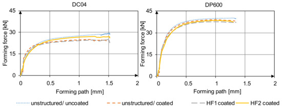
Figure 5.
Results for static plane-strain compression test (f = 0 Hz) experiments with unstructured, HF1-structured, HF2-structured and coated surfaces for DC04 (left) and DP600 (right).
The experiments with an oscillation superimposition were conducted with a frequency of f = 200 Hz and a force amplitude of A = 10 kN. The frequency range selected here has proved to be the most optimal operating point for the hydraulic oscillation device in previous investigations [9]. In order to ensure comparability of the influences of oscillation and surface properties on the forming force, other oscillation parameters were not considered here. Figure 6 shows the averaged forming forces without the representation of the amplitudes and frequency courses. It can be seen that the average forming force decrease for the DP600 and the DC04 specimens with the use of superimposed oscillation is in the range of 31% to 33%. The force path curves for the structured tool surfaces show no clear tendency for the experiments with superimposed oscillation, unlike the static investigations. However, two different explanations have to be considered. One explanation deals with the superposition of numerous different influences, which come about with an oscillation overlay and eventually cancel each other out. This includes the formation of lubrication pockets, which, in combination with tailored surfaces, can cause a damping effect between samples and punches, resulting in a reduction of the oscillatory energy dissipated into the samples. This energy leads to the volume effect for force reduction described in previous studies [25,26,27]. Another influence is the inhibition of the oscillation-induced smoothing effect between the surfaces, which is explained as an additional reason for the oscillation-induced force reduction [9]. An oscillation-induced reduction of friction force was demonstrated in previous research [28,29]. The effects caused by the tailored surfaces and the effects caused by oscillation superimposition do not sum up with respect to the forming force. However, HF1-structured and coated surfaces lead to smaller forming forces than the unstructured coated and lubricated surfaces. This effect is observed for both materials with an oscillation superimposition of f = 200 Hz (see Figure 6). It can be concluded that HF1-structured surfaces lead to a lower friction during forming than surfaces lubricated with Beruforge 152 DL. Compared to the HF2 structure, the HF1 structure reduces the forming force in both static and superimposed oscillation forming. The use of unstructured, coated surfaces also shows a clear effect on friction reduction and thus on forming force reduction.
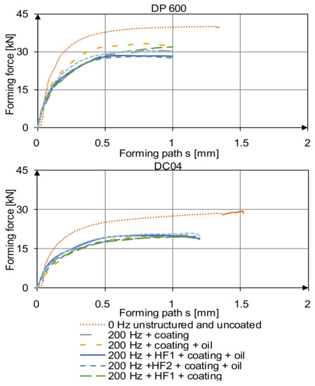
Figure 6.
Forming force of DP 600 samples dependent on oscillating overlay, coating, structuring and oiling (above). Forming force of DC04 samples dependent on oscillating overlay, coating, structuring and oiling (below).
3.2. First Stage of the SBMF
According to the results from the plane-strain compression tests, experiments with coated and HF1-structured tool surfaces were conducted in the first stage of the SBMF process (see Figure 4). Both unstructured and uncoated and HF1-structured and coated stamps were used (see Figure 2). Based on the findings of the plane-strain compression tests, the components described in the test setup were structured and coated with HF1. Rounds with a diameter of 42 mm made out of the steel DC04 were used as semis. The forming force and the forming path were measured by a load cell and a laser sensor during the forming operation. To investigate the direct influence of the structure on the forming force, the experiments were conducted without lubrication. The tests were conducted statically without an oscillation overlay, since the oscillation device does not work with such high forming forces necessary for the first stage of the process. The measurement results of the forming experiments are shown in Figure 7. The results show that a reduction of the forming force through the use of a HF1 structure of the tool surfaces occurs. By using structured and coated tools, the forming force of about 640 kN for the unstructured stamps could be reduced to about 550 kN for the structured stamps (Figure 7). The experiments show that the results from the plane-strain compression tests can be transferred to the SBMF process. A forming force reduction in the range of 17% could be achieved for the non-oscillated plane-strain compression tests due to a coating and a HF1-structured tool surface. The radial and tangential HF1 application in the SBMF process still led to a forming force reduction in the range of 14%. The material flow can be influenced by appropriate friction settings with tailored surfaces, even in more complex forming processes.
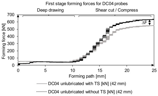
Figure 7.
Non-superimposed oscillation forming experiments with tailored surfaces and unstructured tools in the first stage of the SBMF process. The tailored surfaces (TS) are applied as described in Figure 2.
4. Conclusions
In the scope of this research, the forming behavior of the metallic materials was investigated in relation to coating and surface structuring of the tool active elements in combination with an oscillation superimposition. The results show that the average forming force can be significantly reduced by an oscillation overlay during forming. A structuring and coating of the tool active elements leads to an additional reduction of the average forming force. A material dependency was shown, which leads to the conclusion that surface modifications have to be designed process-dependently. HF1-structured tool surfaces, in combination with an oscillation overlay in the range of 200 Hz, provide the best results regarding forming force reduction (in the range of 31% for the DP600 plane-strain compression test samples and in the range of 33% for the DC04 plane-strain compression test samples). Furthermore, the static forming results with coated and structured tool surfaces could be transferred to the first stage of a SBMF process. As a result, a 14% reduction in process force was achieved in an application-oriented process. A transfer of the knowledge regarding the structuring and coating of the tool active elements in combination with an oscillation overlay on the first stage of the SBMF process will be conducted in a future work.
Author Contributions
Conceptualization, D.S., A.M., S.K., D.F. and P.M.; methodology, S.K., P.M., D.S. and A.M.; software, P.M.; validation, W.T., D.B., D.R. and B.-A.B.; formal analysis, D.S., A.M. and P.M.; investigation, D.S., A.M. and P.M.; resources, B.-A.B., D.B.; W.T.; data curation, D.S., A.M. and P.M.; writing—original draft preparation, D.S., A.M. and P.M.; writing—review and editing, W.T., D.B., D.R. and B.-A.B.; visualization, D.S., A.M. and P.M.; supervision, B.-A.B., D.B.; W.T.; project administration, S.H.; funding acquisition, B.-A.B., D.B.; W.T. All authors have read and agreed to the published version of the manuscript.
Funding
The authors gratefully acknowledge the financial support of the German Research Foundation (DFG) within the transregional collaborative research center TR73 “Manufacturing of complex functional components with variants by using a new sheet metal forming process—Sheet Bulk Metal Forming” projects A7-116817829 (“Dynamic Process Forces”), B3 (“Generation of predetermined surface structures by intentionally invoked self-excited tool vibrations when milling free-formed surfaces”) and B5 (“Application of nanostructured bionic thin layers to enhance the wear and friction behavior of forming tools by thin-walled sheet forming”).
Conflicts of Interest
The authors declare no conflict of interest.
References
- Merklein, M.; Allwood, J.M.; Behrens, B.-A.; Brosius, A.; Hagenah, H.; Kuzman, K.; Mori, K.; Tekkaya, A.-E.; Weckenmann, A. Bulk forming of sheet metal. CIRP Ann. 2012, 61, 725–745. [Google Scholar] [CrossRef]
- Salfeld, V.; Krimm, R.; Hübner, S.; Vucetic, M. Sheet-Bulk Metal Forming of Symmetric and Assymetric Parts. Adv. Mater. Res. 2013, 769, 229–236. [Google Scholar] [CrossRef]
- Nevill, G.E.; Brotzen, E.; Franz, B. The effect of vibrations on the static yield strength of low carbon steel. ASTM Proc. 1957, 57, 751–758. [Google Scholar]
- Blaha, F.; Langenecker, B. Plastizitätsuntersuchungen von Metallkristallen im Ultraschallfeld. Acta Metall. 1959, 7, 93–100. [Google Scholar] [CrossRef]
- Izumi, O.; Oyama, K.; Suzuki, Y. Effects of superimposed ultrasonic vibration on compressive deformation of metals. Trans. Jpn. Inst. Met. 1966, 7, 162–167. [Google Scholar] [CrossRef]
- Bagherzadh, S.; Abinia, K. Effect of ultrasonic vibration on compression behavior and microstructural characteristics of comercially pure aluminium. J. Mater. Eng. Perform. 2015, 24, 4364–4376. [Google Scholar] [CrossRef]
- Bunget, C.; Ngaile, G. Influence of ultrasonic vibration on micro-extrusion. Ultrasonics 2011, 51, 606–616. [Google Scholar] [CrossRef]
- Kirchner, H.O.K.; Kromp, W.K.; Prinz, F.B.; Trimmel, P. Plastic deformation under simultaneous cyclic and unidirectional loading at low and ultrasonic frequencies. Mater. Sci. Eng. 1985, 68, 197–206. [Google Scholar] [CrossRef]
- Koch, S.; Vucetic, M.; Hübner, S.; Bouguecha, A.; Behrens, B.-A. Superimposed oscillating and non-oscillating ring compression tests for sheet-bulk metal forming technology. In Advanced Materials Research; Trans Tech Publications: Stafa-Zurich, Switzerland, 2015; Volume 794, pp. 89–96. [Google Scholar]
- Gröbel, D.; Schult, R.; Hildenbrand, P.; Lechner, M.; Engel, U.; Sieczkarek, P.; Wernicke, S.; Gies, S.; Tekkaya, A.E.; Behrens, B.A.; et al. Manufacturing of functional elements by sheet-bulk metal forming processes. Prod. Process. Ger. Acad. Soc. Prod. Eng. (WGP) 2016, 10, 63–80. [Google Scholar] [CrossRef]
- Behrens, B.-A.; Bouguecha, A.; Vucetic, M.; Hübner, S.; Rosenbusch, D.; Koch, S. Numerical and experimental investigations of multistage sheet-bulk metal forming process with compound press tools. Key Eng. Mater. 2015, 651, 1153–1158. [Google Scholar] [CrossRef]
- Vierzigmann, U.; Merklein, M.; Engel, U. Tailored Surfaces in Sheet-BulkMetal Forming, Tribology of Manufacturing Processes. In Proceedings of the 4th ICTMP International Conference on Tribology in Manufacturing Processes, Nice, France, 13–15 June 2010; Volume 2, pp. 541–550. [Google Scholar]
- Löffler, M.; Andreas, K.; Engel, U.; Schulte, R.; Gröbel, D.; Krebs, E.; Freiburg, D.; Biermann, D.; Stangier, D.; Tillmann, W.; et al. Tribological measures for controlling material flow in sheet-bulk metal forming. Prod. Eng. 2016, 10, 459–470. [Google Scholar] [CrossRef]
- Löffler, M.; Schulte, R.; Freiburg, D.; Biermann, D.; Stangier, D.; Tillmann, W.; Merklein, M. Control of the material flow in sheet-bulk metal forming using modifications of the tool surface. Int. J. Mater. Form. 2019, 12, 17–26. [Google Scholar] [CrossRef]
- Kersting, P.; Gröbel, D.; Merklein, M.; Sieczkarek, P.; Wernicke, S.; Tekkaya, A.E.; Krebs, E.; Freiburg, D.; Biermann, D.; Weikert, T.; et al. Experimental and numerical analysis of tribological effective surfaces for forming tools in Sheet-Bulk Metal Forming. Prod. Eng. 2016, 10, 37–50. [Google Scholar] [CrossRef]
- Tillmann, W.; Stangier, D.; Lopes-Dias, N.-F. Adjustment of friction by duplex-treated, bionic structures for Sheet-Bulk Metal Forming. Tribol. Int. 2017, 111, 9–17. [Google Scholar] [CrossRef]
- Sieczkarek, P.; Wernicke, S.; Gies, S. Wear behavior of tribologically optimized tool surfaces for incremental forming processes. Tribol. Int. 2016, 104, 64–72. [Google Scholar] [CrossRef]
- Podgornik, B.; Hogmark, S.; Sandberg, O. Proper coating selection for improved galling performance of forming tool steel. Wear 2006, 261, 15–21. [Google Scholar] [CrossRef]
- Freiburg, D. Hochvorschubfräsen zur Strukturierung von Werkzeugoberflächen für Die Blechmassivumformung; Vulkan Verlag: Essen, Germany, 2019. [Google Scholar]
- Abele, E.; Dewald, M.; Heimrich, F. Leistungsgrenzen von Hochvorschubstrategien im Werkzeug- und Formenbau. ZWF Z. Wirtsch. Fabr. 2010, 105, 737–743. [Google Scholar] [CrossRef]
- Hense, R.; Kersting, P.; Vierzigmann, U.; Löffler, M.; Biermann, D.; Merklein, M.; Wels, C. High-Feed Milling of Tailored Surfaces for Sheet-Bulk Metal Forming Tools. Prod. Eng. 2015, 9, 215–223. [Google Scholar] [CrossRef]
- Tillmann, W.; Stangier, D.; Hagen, L. Influence of the WC grain size on the properties of PVD/HVOF duplex coatings. Surf. Coat. Technol. 2017, 328, 326–334. [Google Scholar] [CrossRef]
- Tillmann, W.; Hagen, L.; Stangier, D. Influence of etching-pretreatment on nano-grained WC-Co surfaces and properties of PVD/HVOF duplex coatings. Surf. Coat. Technol. 2019, 374, 32–43. [Google Scholar] [CrossRef]
- Becker, N. Weiterentwicklung von Verfahren zur Aufnahme von Fließkurven im Bereich Hoher Umformgrade; Springer: Berlin, Germany, 1994. [Google Scholar]
- Lum, I.; Huang, H.; Chang, B.H.; Mayer, M.; Du, D.; Zhou, Y. Effects of superimposed ultrasound on deformation of gold. J. Appl. Phys. 2009, 105, 024905. [Google Scholar] [CrossRef]
- Huang, H.; Pequegant, A.; Chang, B.H.; Mayer, M.; Du, D.; Zhou, Y. Influence of superimposed ultrasound on deformation of Cu. J. Appl. Phys. 2009, 106, 113514. [Google Scholar] [CrossRef]
- Siu, K.W.; Ngan, A.H.W.; Jones, I.P. New insight on acoustoplasticity-ultrasonic irradiation enhances subgrain formation during deformation. Int. J. Plast. 2011, 27, 788–800. [Google Scholar] [CrossRef]
- Yao, Z.; Kim, G.-Y.; Faidly, L.; Zou, Q.; Mei, D.; Chen, Z. Experimental study of high-frequency vibration assisted micro/mesoscale forming of metallic materials. J. Manuf. Sci. Eng. 2011, 133, 061009. [Google Scholar] [CrossRef]
- Rozner, A.G. Effect of ultrasonic vibration on coefficient of friction during strip drawing. J. Acoust. Soc. Am. 1971, 49, 1368–1371. [Google Scholar] [CrossRef]


© 2020 by the authors. Licensee MDPI, Basel, Switzerland. This article is an open access article distributed under the terms and conditions of the Creative Commons Attribution (CC BY) license (http://creativecommons.org/licenses/by/4.0/).