Article

An Investigation into Tool Wear and Hole Quality during Low-Frequency Vibration-Assisted Drilling of CFRP/Ti6Al4V Stack

by
Ramy Hussein
1,*,
Ahmad Sadek
2,
Mohamed A. Elbestawi
1 and
M. Helmi Attia
2
1
Department of Mechanical Engineering, McMaster University, Hamilton, ON L8S 4L7, Canada
2
Aerospace Manufacturing Technology Centre, National Research Council Canada, Montreal, QC H3T 2B2, Canada
*
Author to whom correspondence should be addressed.
J. Manuf. Mater. Process. 2019, 3(3), 63; https://doi.org/10.3390/jmmp3030063
Submission received: 4 June 2019 / Revised: 6 July 2019 / Accepted: 25 July 2019 / Published: 27 July 2019

Abstract

:
The use of lightweight material such as CFRP/Ti6Al4V in stacked structures in the aerospace industry is associated with improved physical and mechanical characteristics. The drilling process of nonuniform structures plays a significant role prior to the assembly operation. However, this drilling process is typically associated with unacceptable CFRP delamination, hole accuracy, and high tool wear. These machining difficulties are attributed to high thermal load and poor chip evacuation mechanism. Low-frequency vibration-assisted drilling (LF-VAD) is an advanced manufacturing technique where the dynamic change of the uncut chip thickness is used to manipulate the cutting energy. An efficient chip evacuation mechanism was achieved through axial tool oscillation. This study investigates the effect of vibration-assisted drilling machining parameters on tool wear mechanisms. The paper also presents the effect of tool wear progression on drilled hole quality. Hole quality is described by CFRP entry and exit delamination and hole accuracy. The results showed a significant reduction in the thrust force, cutting torque, cutting temperature, and flank wear-land.

1. Introduction

Superior physical and mechanical characteristics, such as high strength to weight ratio, low coefficient of thermal expansion, fatigue resistance, and corrosion/erosion resistance [1,2,3], explain the growing usage of carbon fiber reinforced polymers (CFRP) and Ti6Al4V in the aerospace industry. The hybrid structure of CFRP/Ti coupling (CFRP/Ti, CFRP/Ti/CFRP, and Ti/CFRP/Ti) has been identified as the common selection in the new generation of aircraft [4,5]. Good reliability, convenient inspection, and easy detachability are of the main advantages of mechanical fastening that are typically used in the assembly process of different materials in the load carrying members, consequently making the drilling process of CFRP and Ti6Al4V a necessity prior to the assembly process.
The conventional drilling process of CFRP is commonly associated with surface integrity defects such as entry and exit delamination and matrix thermal damage [6,7,8,9]. These machining difficulties are attributed to the high sensitivity to cutting energy and anisotropic mechanical properties [10,11]. To achieve a long tool life with proper machining performance, excessive experimental investigation using different tool material were conducted to understand the main wear mechanism. Carbide drills show a preferable drilling performance over the high-speed steel (HSS) for higher hot hardness, while polycrystalline diamond (PCD) cost adds more limitation for mass manufacturing. Abrasive wear has been identified as the dominant wear mechanism during the drilling process of CFRP [12,13,14]. This wear mechanism was attributed to hard and soft abrasion modes [14]. The hard mode is located at WC grains due to the generated dynamic stresses from the broken fiber, material reinforcement, and powder like chips [15]. Consequently, the WC grains suffer crack initiation and propagation fracture [16]. On the other hand, the relatively low hardness Co binder is more easily damaged by carbon fibers (CF) in a process known as soft abrasion mode [14,17,18]. Hence, WC grain spalling is more rapid under the cyclic machining load.
High cutting temperature, poor chip evacuation mechanism, and burr formation are of the common issue during the drilling process of Ti6Al4V [19,20,21]. These problems resulted in a higher probability of flute-chip accumulation, progressive tool wear, and poor surface integrity [19,20,22]. Low thermal conductivity and high chemical affinity to the majority of tool materials are due to the adverse titanium characteristics, which resulted in a significant reduction in the tool life with a high probability of catastrophic failure [20,23,24]. This effect contributed to the cutting stress concentration on the tool cutting edge where the maximum cutting temperature is located. Therefore, the machining process of Ti6Al4V is typically associated with the formation of built-up-edge (BUE). The formation of BUE has a significant drawback on the machined surface integrity and the tool life [25,26]. Thus, adding more limitations in the aerospace production procedure [27].
Despite, the extensive to optimize separate machining process of both materials, the machining process suffers when it comes to production time, cost, and assembly positional error. Single process drilling of the CFRP and Ti6Al4V materials in situ, also known as stacked drilling shows considerable benefits to overcome separate drilling issues [1,2,3,28,29]. However, the stack drilling of CFRP and Ti6Al4V materials represents a challenge for the aerospace industry [4]. The optimal machining parameters of each material are conflicting, and consequently the machining process could produce undesirable effects. For example, the accumulation of high-temperature titanium chips inside the limited evacuation space (drill flutes), results in CFRP thermal damage, high exit delamination, and chip–tool adhesion.
The experimental investigation of composite/metallic stack drilling showed contrary results, compared to the separate drilling process of each material. The average entry delamination of CFRP was increased from less than 2 mm at CFRP separate drilling to 13 mm at CFRP/Ti6Al4V stack drilling [5]. In addition, the surface roughness during stack drilling is more than double that for the separate drilling of CFRP. These increases of entry delamination and surface roughness contributed to the effect of titanium adhesion on the drill bit margins. The poor surface roughness of CFRP and Ti6Al4V during stack drilling was confirmed in [30]. The author attributed this reduction in surface quality to the fast tool wear mechanism during stack drilling. Increasing the cutting temperature during the drilling process of Ti6Al4V resulted in a higher adhesion that leads to BUE formation [31,32]. Consequently, the cutting edge sharpness decreased and the entry delamination increased. Tool wear has been confirmed to be much faster during the stack drilling, as reported in [4,33].
Conversely, entry delamination showed a clear reduction during the CFRP/Ti6Al4V stack drilling [30]. Moreover, the utilization of titanium plate as a backing material for CFRP would result in a clear reduction of exit delamination. Compared to the separate drilling process of CFRP, the exit delamination was found to be much lower during the stack drilling [30,33]. The fiber pull-out was completely extinct during the stack drilling process. In addition, stack drilling reduced the surface roughness of the CFRP, while Ti6Al4V was rougher than separate drilling [33]. The reduction of Ti surface quality was attributed to the abrasive effect of the CFRP chip. The tool life during stack drilling increased three times compared to the separate drilling of titanium material [34]. Compared to HSS, the carbide drill showed proper machining performance with lower flank wear-land [28]. This advantage was attributed to the higher hot hardness of the carbide tool. In addition, the machining parameters such as cutting speed and feed rate showed a direct impact on the flank wear progress. Despite the limited observation of Ti adhesion during the drilling process using PCD, the cutting edge showed severe chipping compared to carbide drill [23].
Several approaches have been implemented to overcome the stack drilling machining difficulties through machining parameters optimization [2,35,36], two-step drilling process [3], and the utilization of an advanced lubricant and tool coating to reduce the chip-tool friction [37]. Advanced machining process such as vibration-assisted drilling (VAD) where the axial feed is superimposed by a harmonic motion [38,39], can be seen as a promising candidate to attain better machining quality. This is possibly due to the significant benefit of changing the chip morphology from continuous to segmented [40,41,42] and the efficient chip evacuation mechanism [40,43].
The experimental investigation of low-frequency vibration-assisted drilling (LF-VAD) of CFRP/Ti6Al4V showed promising results compared to the conventional drilling (CD) [38,44]. The utilization of 1.5 cycle/rev frequency with minimum quantity lubrication (MQL) resulted in a 43% reduction in the cutting temperature with improved surface integrity [44]. Increasing the modulation frequency to 2.5 cycle/rev frequency resulted in a 56% reduction in the cutting temperature with enhanced surface integrity, significant reduction of the entry and exit delamination, and the generation of compressive residual stresses in the machined Ti6Al4V surface, as summarized in Figure 1 [38].
Compared to conventional drilling (CD), VAD showed significant enhancement of the CFRP/Ti6Al4V stack drilling process. However, there is limited understanding of the machining performance and tool wear progress in VAD stack drilling, in spite of its extensive possible impact in the industry. VAD using the ultrafrequency range (39 KHz frequency) increased tool life compared to CD [45]. However, as the cutting speed increased, this effect was reduced. On the other hand, the effect of LF-VAD using 1.5 oscillation/rev with a maximum of 1000 rpm cutting speed showed an apparent reduction on the tool wear as reported in [46,47]. Despite the significant enhancement of VAD on the tool life, the available literature focused only on the thrust forces, temperature, and wear-land. The effect of tool wear progression on drilled hole quality, such as delamination and geometrical accuracy, was not discussed, representing the key factor in the aerospace industry. Our previous investigation of LF-VAD of CFRP/Ti6Al4V has mainly focused on presenting the effect of a wide range of machining parameters on the cutting forces, temperature, surface integrity, microstructure, and the induced residual stresses [38]. Based on that study, a modulation amplitude in the range of 0.1 to 0.25 mm was recommended to achieve proper machining quality. The current study presents the effect of the selected LF-VAD machining parameters on the tool wear mechanism and the associated influence on the machining forces, temperature, and hole quality. The hole quality parameters are presented in terms of geometrical accuracy, entry CFRP delamination, and exit CFRP delamination. In addition, hole quality is linked to the cutting forces to generate a machining map for industrial application.

2. Experimental Setup

The drilling process was conducted using a five-axis Makino A 88 machining center, as described in Figure 2. A special set-up was designed to install the MITIS tool holder MITIS tool PG8045B3_HSK-A100_ER40 and hold the FLIR SC8000 HD Series infrared camera. The MITIS tool holder has a fixed 2.5 oscillation/rev modulation frequency, 3500 rpm speed limitation, and adjustable amplitude of 0.01 to 0.48 mm. To monitor the cutting temperature, a fixed distance was set between the drilled material and dynamometer to achieve a direct view of the drill tool at the Ti6Al4V exit surface by tilting the thermovision infrared camera. The cutting forces were measured using a Kistler four-component dynamometer type 9272 and supported by Kistler Multichannel Charge Amplifier type 5019 B.
Based on the typically drilled diameter in the aerospace industry, an OSG 6 mm tungsten carbide (WC) twist drill was used for the test matrix. The drill bit has a 118° point angle and a 20° helix angle. The CFRP/Ti6Al4V stacked material specimen has a 120 mm side length and 12.55 mm thickness (5.8 ± 0.02 mm for CFRP and 6.75 ± 0.02 mm for Ti6Al4V). The CFRP has 42 × L-930(GT700) woven plies with the [[0,90]21]s configuration and flame retardant modified epoxy prepreg (320 °C decomposition temperature), while the Ti6Al4V plate was produced according to grade 5 standard. Machining parameters were selected based on the previous experimental investigation [38], where the test matrix consisted of two levels cutting speeds (N) (37.68 and 56.52 m/min), two levels of feed rates (f) (0.025 and 0.075 mm/rev), and three modulation amplitudes (Am) (0.1, 0.16, and 0.25 mm). To ensure a good machining productivity rate, the 37.68 m/min and 0.025 mm/rev combined machining conditions were ignored. The tool wear progress and hole quality study were conducted over a dry drilling process of 50 drilled holes. The flank wear-land progress was measured at drilled hole number 5, 10, 20, 30, 40, and 50 using the Winslow engineering tool analyzer model 560. The flank surface was examined using Scanning Electron Microscopy (SEM) and Energy-Dispersive X-ray Spectroscopy (EDS) was used to identify the adhered particles chemical composition. The rounding of the cutting edge was calculated at a normal distance of 500 µm from the cutting edge margin using an Alicona microscope. While the entry and exit CFRP delamination were evaluated using a Keynece Digital Microscope, the hole diameter error was calculated by taking an average of ten points on the top and bottom surfaces for both materials using a Mitutoyo Coordinate Measuring Machine (CMM).

3. Results and Discussion

3.1. Effect of Tool Wear on the Thrust Force

Drilling forces analysis is a fundamental step through which the effect of chip evacuation efficiency and tool wear progress can be predicted. Figure 3 shows the measured drilling forces for the investigated drilled holes for N = 56.52 m/min at different vibration amplitudes and feed rates. As the drilled holes number increases the cutting forces gradually increases for CD and VAD, which can be attributed to tool wear progress. For f = 0.025 mm/rev, the CD thrust force and cutting torque increase rates become higher after drilled hole number 30. This observation indicates strong evidence of a change in the cutting edge geometry that resulted in high cutting and friction forces. Moreover, the high cutting torque could reflect poor chip evacuation, which has a negative effect on the machined surface integrity, as will be presented later. On the contrary, VAD showed a low thrust force and cutting torque increase rates. Compared to CD, the maximum thrust force and cutting torque showed a 25% and 45% reduction for Am = 0.1 mm and a 15% and 25% reduction for Am = 0.25 mm, respectively. This reduction can be attributed to the enhanced chip evacuation and the expected low cutting temperature [38,46,47], as will be explained in the next section. Consequently, the drill tool material maintained its hardness with a sharp cutting edge geometry at low cutting temperature. Also, the low reduction percentages of cutting forces for high modulation amplitude can be attributed to the higher impact load [40]. For f = 0.075 mm/rev, the CD drilling process was stopped after drill hole number 2, due to the observation of the tool-chip welding process as shown in Figure 4A. This phenomenon was due to the combined effect of excessive thermal load and poor chip evacuation that resulted in tool-chip welding. In addition, this conclusion was confirmed by the significant increase of the cutting torque by 400% (from 4 Nm to 16.9 Nm). Comparatively, the drilled holes number increased with the use of VAD. The maximum drilled number of holes reached was 10 for Am = 0.1 mm, which was doubled for Am = 0.25 mm, before the observation of tool-chips welding process as shown in Figure 4B,C. Increasing the number of holes drilled with higher amplitude can be attributed to the lower thermal load, small chip radian, and enhanced evacuation efficiency [38,40,41,43].
Reducing the cutting speed to N = 37.68 m/min resulted in a relatively low thrust force and cutting torque for both machining techniques. The measured cutting forces for VAD did not show any change over the 50 drilled holes, as shown in Figure 5. However, the thrust forces increased with amplitude due to the cyclic tool–workpiece impact [40]. All VAD tests at Am = 0.1 mm, 0.16 mm, and 0.25 mm experienced a negligible increase of the thrust force with a number of holes. However, the test performed at Am = 0.1 mm was stopped due to the tool-chip welding, which is in agreement with the results reported previously in [38]. The cutting torque in CD increased at a high rate after drilled hole number 20, as shown in Figure 5B. This increase could indicate poor evacuation efficiency and progressive tool wear, as will be presented in the next section.

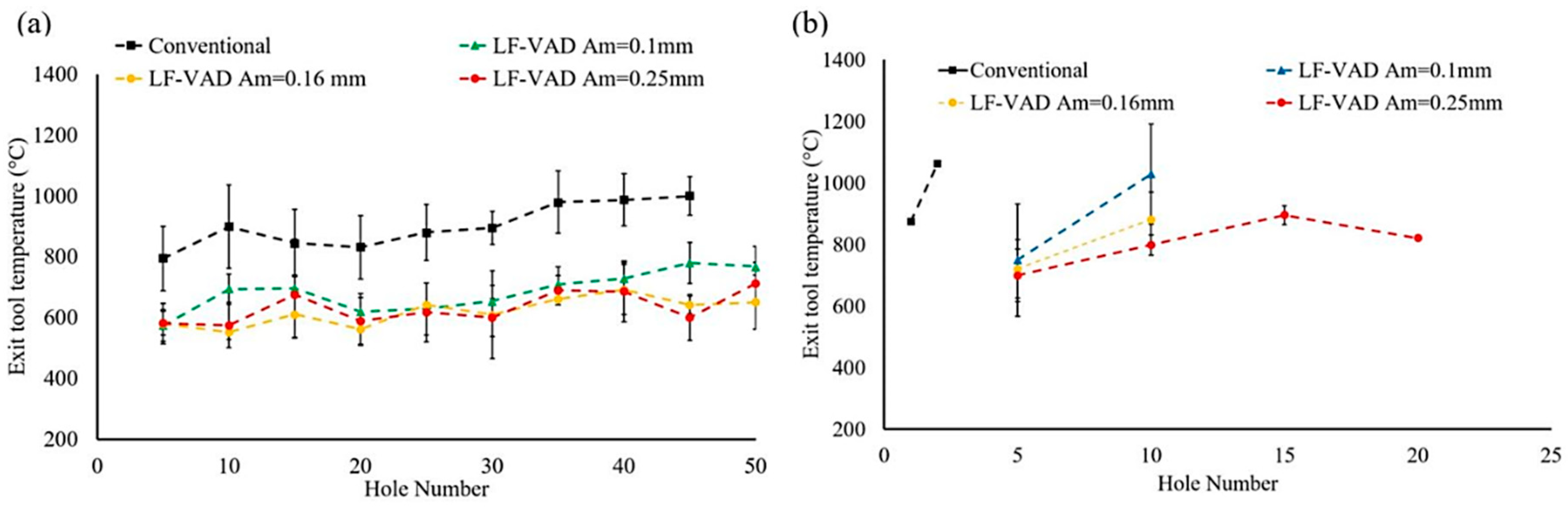
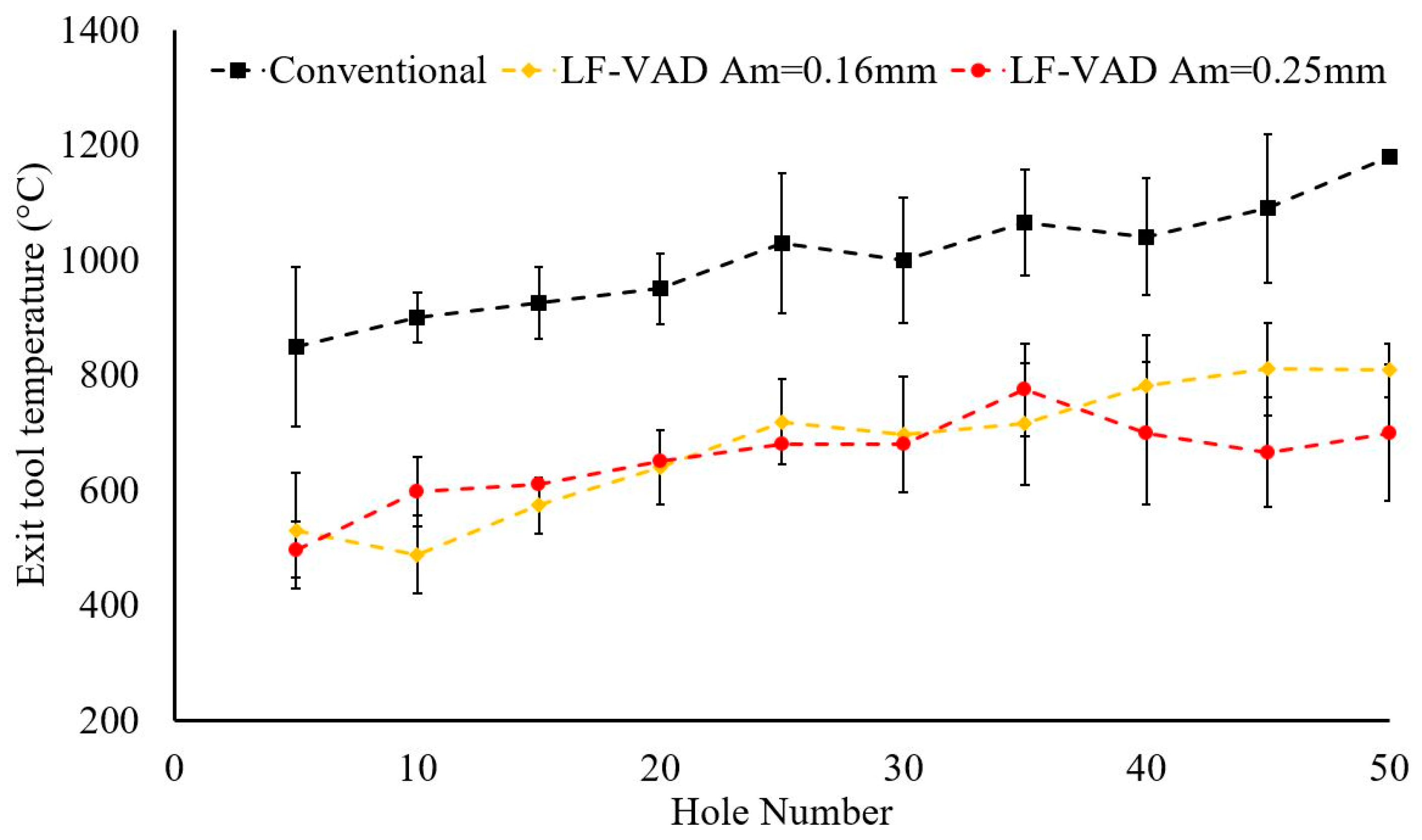
3.2. Effect of Tool Wear on the Cutting Temperature

Figure 6 shows the measured tool tip temperature at the exit machined surface for N = 56.52 m/min at different machining feed rates and amplitudes. For f = 0.025 mm/rev, the utilization of LF-VAD resulted in up to 40% reduction in the thermal load compared to CD. This reduction could be attributed to (a) the significant change of the Ti6Al4V chip morphology from a continuous spiral shape for CD to a segmented one [38,40], (b) the enhanced chip evacuation efficiency due to the tool axial oscillation mechanism [38,40,43], and (c) the cyclic cooling interval during the interrupted cutting process [40]. Moreover, increasing the modulation amplitude for VAD resulted in a lower tool tip temperature. This reduction can be tracked back to the lower duty cycle and the increased cooling cycle [40]. Examining the cutting temperature across the drilled holes for CD, a relative temperature increase was observed after drilled holes number 30. This observation matches the increased cutting forces, as presented in Section 3.1. Consequently, severe adhesion tool wear mechanism could be expected at this point. For f = 0.075 mm/rev, LF-VAD with Am = 0.25 mm resulted in 820 °C cutting temperature after 20 drilled holes, compared to 1070 °C after the second drilled hole with CD technique. The high cutting temperature for both machining techniques resulted in tool–chip welding, which has a negative effect on the machined hole quality, as will be described in the next section. However, the benefit of VAD in reducing the machining thermal load can clearly be noticed even at high cutting speed and feed.
The machining thermal load showed a dropped relatively at the low cutting speed N = 37.68 m/min, compared to N = 56.52 m/min, as shown in Figure 7. This reduction resulted in a successful drilling process of 50 holes for VAD and CD without any observation of the tool-chip welding process. This enhancement could be attributed to the lower chip velocity that prevents the flute chips jamming. Therefore, the problem of the tool-chip welding process was avoided even with the observation of 1180 °C tool tip temperature for CD at drill hole number 50.

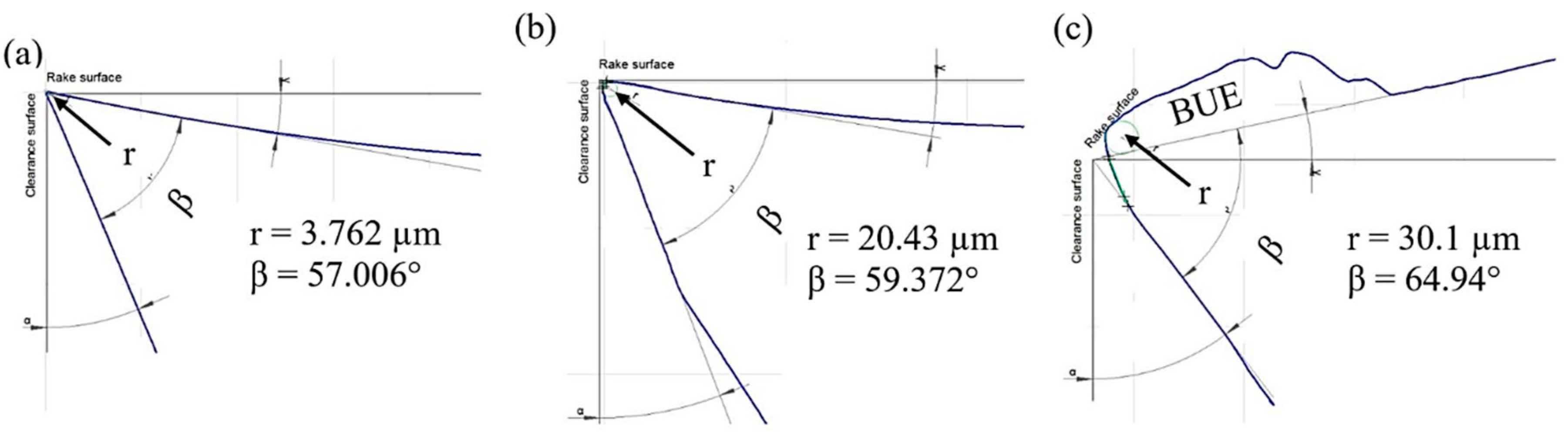
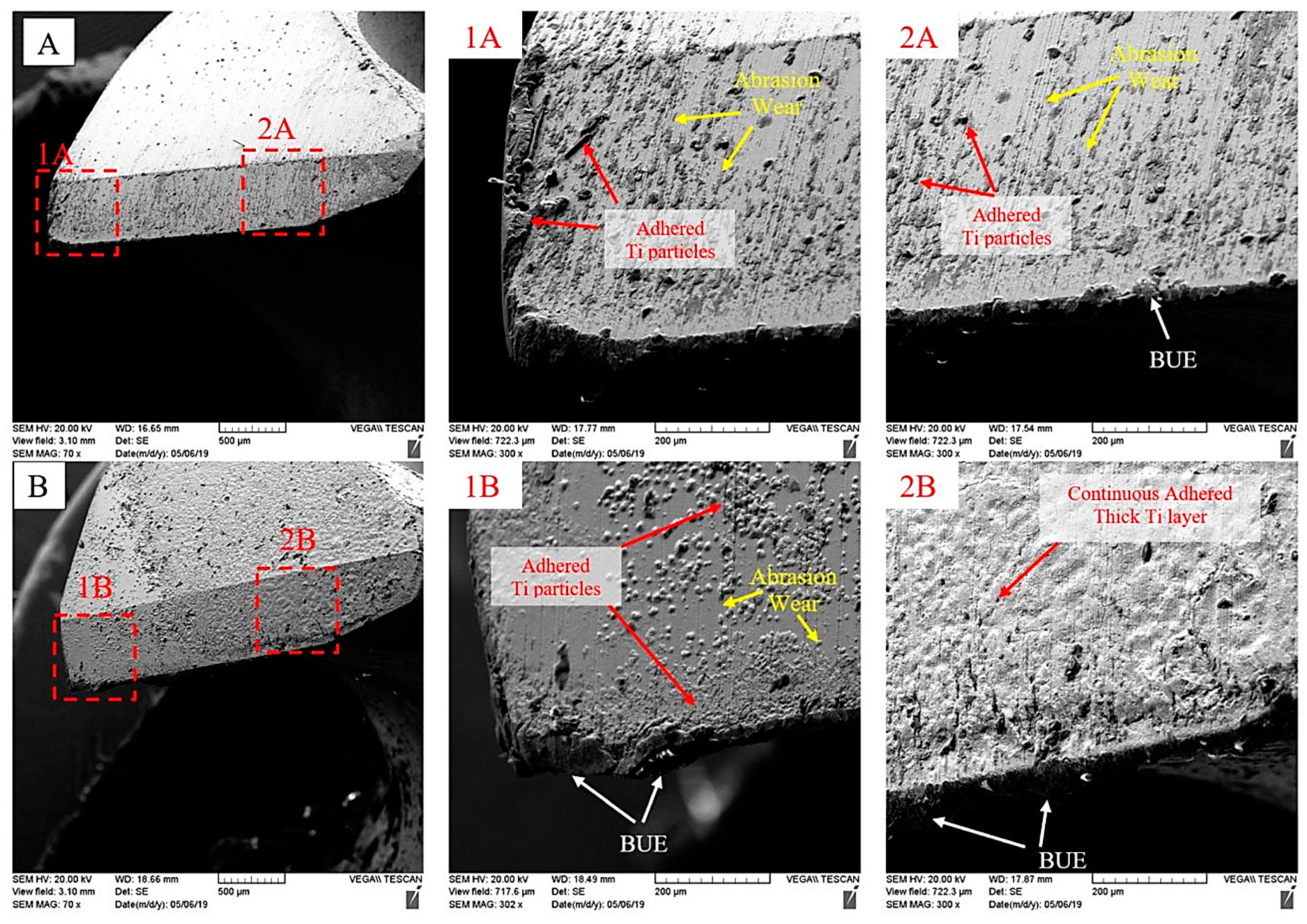
3.3. Tool Wear Mechanism and Progression

The effect of LF-VAD modulation amplitude on the flank wear-land was examined using the Winslow tool analyzer. Figure 8 shows the flank wear-land (VB) progress for N = 56.52 m/min at different feed rates and vibration amplitudes. For all machining conditions, LF-VAD resulted in a lower flank wear-land compared to CD. The flank wear progress passes through three distinct regions: initial wear, steady wear, and severe wear. The machining process with new cutting edge resulted in concentrated cutting forces over a narrow contact area (small cutting edge radius). Consequently, high stresses are generated and the wear progress will be high known as initial wear region (A). This process increases the tool–workpiece contact area thus reducing the generated cutting stresses on the tool cutting edges. Hence the tool wear progress will be low, also known as steady wear region (B). The continuity of the machining process with a wide tool–workpiece contact area resulted in high mechanical and thermal loads that increase the wear progress extremely, manifested in the severe wear region (C).
For CD at f = 0.025 mm/rev, the VB increased at a relatively higher rate compared to LF-VAD to reach 100 µm at the drill hole number 20, representing the initial wear region. This rate declined afterward until VB reached 117 µm at drill hole number 30, where the steady wear is located, then increased to 327 µm at the drill hole number 40, as shown in Figure 8a. The severe wear region represents the criterion for the drilling process termination, according to ISO 3685 (VB = 300 µm) [48]. It is also noted that transformation from steady to severe wear was recorded at the drilled hole number 30, where high mechanical (thrust force and cutting torque) and thermal loads (cutting temperature) were experienced, as described in Section 3.1 and Section 3.2. The initial wear region for VAD took place until hole number 10 only, which is 10 holes earlier compared to CD (20 holes). This can be attributed to the excessive impact load associated with VAD process [40]. However, the maximum VB for VAD was 85 µm at drill hole number 50, which is 75% lower than CD due to the low thermal load and proper chip evacuation.
Increasing the machining feed to 0.075 mm/rev resulted in a severe limitation on the maximum number of drilled holes for all machining conditions, as shown in Figure 8b. This limitation was due to the observation of the tool-chip welding problem that contributed to the high cutting temperature and poor chip evacuation efficiency, as shown in Figure 4. For CD, the burned and welded Ti chip was observed after the second drilled hole. Conversely, increasing the vibration amplitude from 0.1 mm to 0.25 mm resulted in an increase in the total drilled holes number by 100%. This enhancement was mainly due to the lower cutting temperature and proper chip evacuation [38].
Figure 9 shows the effect of CD and VAD on the flank wear-land at N = 37.68 m/min and f = 0.075 mm/rev. Based on the measured flank wear-land, VAD with Am = 0.25 reduced the wear progress by 45% without any observation of the tool-chip welding, as shown in Figure 10. Low thermal load and high chip evacuation efficiency were of the main factors controlling this result.
To understand the different tool wear mechanisms of the tested machining conditions, Figure 11 shows the scanning electron microscopy (SEM) examination of CD and VAD at Am = 0.25 mm at the maximum drilled hole number (40 for CD and 50 for VAD). Strong evidence of abrasion and adhesion tool wear mechanism for VAD techniques are shown in Figure 11A. Scratches on the flank face resulted from the abrasion wear mechanism, mainly caused by the tool relative motion with respect to the hard carbon fibers, broken fibers, and the powder chips particles [14,15] during the drilling process of CFRP layer. The adhesion wear mechanism of Ti was confirmed using the energy-dispersive X-ray spectroscopy (EDS) analysis of the selected points in Figure 11, as shown in Table 1. In the case of CD, a massive amount of adhered Ti particles with BUE formation was observed, as shown in Figure 11B. The formation of BUE has a severe drawback on the drill hole quality, and the breakage of the BUE fragments resulted in tool chipping and fracture. The severe tool chipping and fracture increased the cutting edge radius (CER) to 30 µm, compared to 20 µm for VAD after 50 drilled holes, as shown in Figure 12. Based on the observation of a large and continuous adhesion layer (Figure 11 (1B)) and the EDS analysis of the selected points (3–5), the adhesion wear was confirmed as the dominant wear mechanism for CD. This mechanism was developed as a result of the higher thermal load, poor cooling mechanism, continuous tool–workpiece contact, and the high affinity of Ti to chemically react with the tool material [31,32,49,50].
Figure 13 shows the SEM images of the flank surface at N = 37.68 min and f = 0.075 mm/rev for VAD (Am = 0.25 mm) and CD. Using a machining process with low cutting speed reduced the adhered Ti particles for both machining techniques. For VAD, abrasion and adhesion wear mechanism could obviously be identified along the flank surface. On the other hand, for CD, the flank surface was covered with a continuous Ti layer with BUE formation. This could be attributed to the high thermal load during the conventional drilling process. Moreover, the CER for VAD and CD was reduced from 20 µm and 30 µm at N = 56.52 m/min to 16.89 µm and 19.34 µm, respectively, at N = 37.68 m/min, as shown in Figure 14.

3.4. Effect of Tool Wear on Drilled Hole Quality

3.4.1. CFRP Entry Delamination

The delamination factor (φd) for all machined parameters was calculated based on Equation (1):
φ d = D a c t u a l D n o m i n a l D n o m i n a l
where Dactual is the diameter of a circle including the circumscribing delamination, while Dnominal represents the nominal hole diameter.
For all machining conditions, VAD resulted in a lower entry delamination factor compared to CD, as shown in Figure 15 and Figure 16. Based on the defined aerospace limitation (φd ≤ 0.5) [39,51], the delamination factor in CD was acceptable until drilled hole number 20 for N = 37.68 m/min, which is correlated to 460 N thrust force, as shown in Figure 15b. Increasing the cutting speed to 56.52 m/min reduced the entry delamination for f = 0.025 mm/rev by an average of 50%, which remained within the acceptable limit for all tool wear levels. The maximum entry delamination value (φd = 0.26) for all VAD tests was considerably less than the allowable limit. The effect of VAD compared to CD on enhancing the entry delamination was most evident at the final drilled hole, as shown in Figure 17.

3.4.2. CFRP Exit Delamination

Figure 18a,b shows the change in exit delamination with the increase of the number of holes and the thrust force in CD and VAD, respectively. For N = 37.68 m/min, CD showed acceptable delamination until the drilled hole number 20, which is corresponds to a 450 N thrust force. This interval represents the initial wear region. Increasing the flank wear resulted in a higher thermal and mechanical load, which formed larger exit delamination at the severe wear region (starting from hole number 30).
For N = 56.52 m/min, the CD resulted in excessive exit delamination for all feed rates, as shown in Figure 19 and Figure 20. On the other hand, VAD showed acceptable delamination for all feed rates, except the final drilled hole at f = 0.075 mm/rev where tool-chip welding was observed.

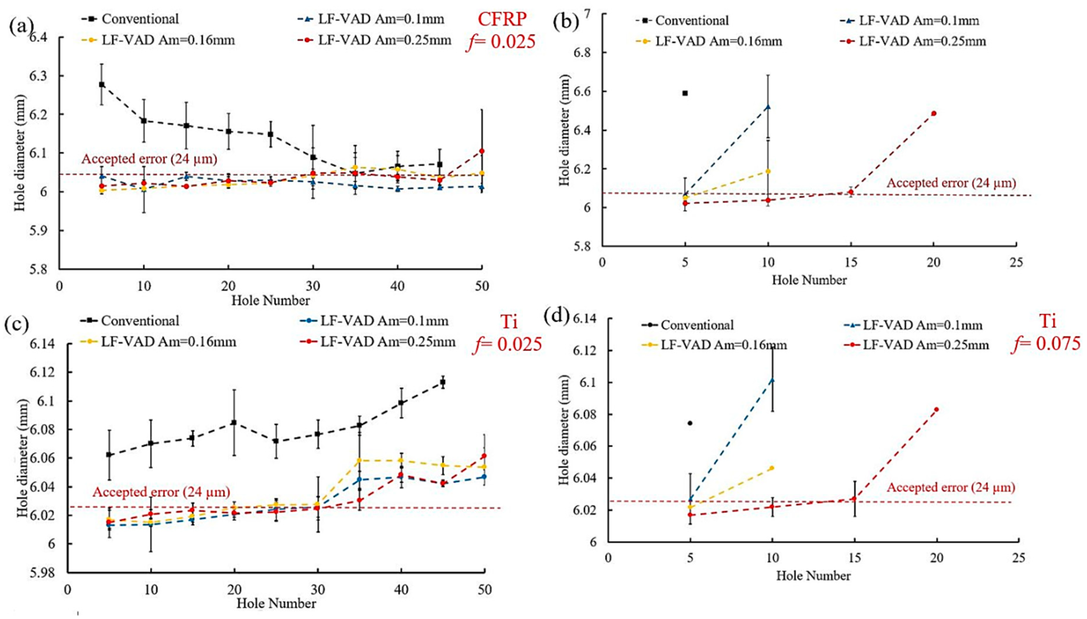
3.4.3. Hole Size Accuracy

Based on the defined hole size error for aerospace limitation (−0.7% to 0.4%) [38,39], CD exceeds the acceptable CFRP and Ti6Al4V hole size at N = 37.68 m/min, as shown in Figure 21. The excessive CFRP error for CD could be attributed to the poor evacuation of the continuous Ti6Al4V chip at high temperature. Additionally, the relatively higher hole size error in CFRP compared to Ti6Al4V can be attributed to rubbing of the CFRP hole walls by the continuous Ti chips transferred to the CFRP layer in CD. On the other hand, VAD showed an acceptable hole size over the investigated drilled holes. Increasing the cutting speed to 56.52 m/min, resulted in an acceptable CFRP hole size for VAD, while the Ti6Al4V exceeded the proper range after hole number 30, as shown in Figure 22, as a result of tool wear. For f = 0.075 mm/rev, the VAD hole size was acceptable until the formation of the tool-chip welding process.

4. Conclusions

In this research, tool wear behavior during low-frequency vibration-assisted drilling has been evaluated. The experimental investigation examined the drilling of 50 holes under various machining conditions. Three modulation amplitudes were selected based on a previous wide range study. The cutting edge examination using electron microscopy confirmed abrasion and adhesion tool wear mechanism for VAD, while the adhesion mechanism was dominant for CD. Low flank wear-land, cutting edge rounding, and relatively optimum hole quality were observed at 37.68 m/min cutting speed and 0.075 mm/rev feed. Based on the experimental results, the main observations are as follows.
  • As the drilled hole number increased, the cutting torque and thrust increased for both machining techniques. However, VAD resulted in up to 25% and 45% reduction in the thrust force and cutting torque, respectively.
  • For N = 56.52 m/min cutting speed and 0.075 feed, increasing the modulation amplitude hindered the tool-chip welding.
  • LF-VAD showed a significant reduction in the machining thermal load. The exit cutting temperature was reduced by 40%, compared to the CD.
  • Up to 75% reduction on the flank wear-land was achieved by VAD with high modulation amplitude. Moreover, the tool surface profile examination showed a low cutting edge roundness (CER) compared to the conventional machining process.
  • Vibration-assisted drilling showed an acceptable entry and exit delamination for all the investigated machining parameters.
  • The effect of tool wear progress was significant for CD at low cutting speed, while the high thermal load and poor evacuation efficiency resulted in un-acceptable delamination at the high cutting speed.
  • A significant enhancement of the CFRP and Ti6Al4V geometrical accuracy has been achieved by VAD, compared to CD.

Author Contributions

R.H. performed experiments, analysis, and data interpretation; wrote the first draft of the manuscript; and helped with submitting the final manuscript to the journal (corresponding author). A.S. helped with the experiments and analysis and revised the manuscript. M.A.E. revised and edited the manuscript and gave the final approval to be submitted. M.H.A. revised the manuscript.

Funding

This research received no external funding.

Conflicts of Interest

The authors declare no conflicts of interest.

Acronyms

VADVibration-assisted drilling
LF-VADLow frequency-vibration-assisted drilling
CDConventional drilling
HSSHigh-speed steel
BUEBuilt-up edge
AInitial wear region
BSteady wear region
CSevere wear region
CERCutting edge radius
VBAverage flank wear-land

Notations

NCutting speed [m/min]
fFeed rate [mm/rev]
AmModulation amplitude [mm]
FFrequency [Hz]
ØdDelamination factor [%]

References

  1. Ramulu, M.; Branson, T.; Kim, D. A study on the drilling of composite and titanium stacks. Compos. Struct. 2001, 54, 67–77. [Google Scholar] [CrossRef]
  2. Kim, D.; Ramulu, M. Study on the Drilling of Titanium/Graphite Hybrid Composites. J. Eng. Mater. Technol. 2007, 129, 390–396. [Google Scholar] [CrossRef]
  3. Brinksmeier, E.; Janssen, R. Drilling of Multi-Layer Composite Materials consisting of Carbon Fiber Reinforced Plastics (CFRP), Titanium and Aluminum Alloys. CIRP Ann. 2002, 51, 87–90. [Google Scholar] [CrossRef]
  4. Xu, J.; Mkaddem, A.; El Mansori, M. Recent advances in drilling hybrid FRP/Ti composite: A state-of-the-art review. Compos. Struct. 2016, 135, 316–338. [Google Scholar] [CrossRef] [Green Version]
  5. Park, K.H.; Beal, A.; Kwon, P.; Lantrip, J. A comparative study of carbide tools in drilling of CFRP and CFRP-Ti stacks. J. Manuf. Sci. Eng. 2014, 136, 014501. [Google Scholar] [CrossRef]
  6. Persson, E.; Eriksson, I.; Zackrisson, L. Effects of hole machining defects on strength and fatigue life of composite laminates. Compos. Part A Appl. Sci. Manuf. 1997, 28, 141–151. [Google Scholar] [CrossRef]
  7. Chen, W.C. Some experimental investigations in the drilling of carbon fiber-reinforced plastic (CFRP) composite laminates. Int. J. Mach. Tools Manuf. 1997, 37, 1097–1108. [Google Scholar] [CrossRef]
  8. Gaitonde, V.; Karnik, S.; Rubio, J.C.; Correia, A.E.; Abrão, A.; Davim, J.P.; Abrao, A.; Gaitonde, V. Analysis of parametric influence on delamination in high-speed drilling of carbon fiber reinforced plastic composites. J. Mater. Process. Technol. 2008, 203, 431–438. [Google Scholar] [CrossRef]
  9. Romoli, L.; Dini, G. Experimental study on the influence of drill wear in CFRP drilling processes. In Proceedings of the ICME 08, Naples, Italy, 23–25 July 2008. [Google Scholar]
  10. Che, D.; Saxena, I.; Han, P.; Guo, P.; Ehmann, K.F. Machining of Carbon Fiber Reinforced Plastics/Polymers: A Literature Review. J. Manuf. Sci. Eng. 2014, 136, 034001. [Google Scholar] [CrossRef]
  11. Liu, D.; Tang, Y.; Cong, W. A review of mechanical drilling for composite laminates. Compos. Struct. 2012, 94, 1265–1279. [Google Scholar] [CrossRef]
  12. Malhotra, S. Some studies on drilling of fibrous composites. J. Mater. Process. Technol. 1990, 24, 291–300. [Google Scholar] [CrossRef]
  13. Lin, S.; Chen, I. Drilling carbon fiber-reinforced composite material at high speed. Wear 1996, 194, 156–162. [Google Scholar] [CrossRef]
  14. Rawat, S.; Attia, H. Wear mechanisms and tool life management of WC–Co drills during dry high speed drilling of woven carbon fibre composites. Wear 2009, 267, 1022–1030. [Google Scholar] [CrossRef]
  15. Teti, R. Machining of composite materials. CIRP Ann. Manuf. Technol. 2002, 51, 611–634. [Google Scholar] [CrossRef]
  16. Masuda, M.; Kuroshima, Y.; Chujo, Y. Failure of tungsten carbide-cobalt alloy tools in machining of carbon materials. Wear 1993, 169, 135–140. [Google Scholar] [CrossRef]
  17. Larsen-Basse, J.; Koyanagi, E. Abrasion of WC-Co alloys by quartz. J. Lubr. Technol. 1979, 101, 208–211. [Google Scholar] [CrossRef]
  18. Larsen-Basse, J. Abrasion Mechanisms—Delamination to Machining. Fundam. Tribol. 1978, 679–689. [Google Scholar]
  19. Dornfeld, D.; Kim, J.; Dechow, H.; Hewson, J.; Chen, L. Drilling Burr Formation in Titanium Alloy, Ti-6Al-4V. CIRP Ann. Manuf. Technol. 1999, 48, 73–76. [Google Scholar] [CrossRef]
  20. Zhang, P.; Churi, N.; Pei, Z.J.; Treadwell, C. Mechanical drilling processes for titanium alloys: A literature review. Mach. Sci. Technol. 2008, 12, 417–444. [Google Scholar] [CrossRef]
  21. Cantero, J.L.; Tardío, M.M.; Canteli, J.A.; Marcos, M.; Miguélez, M.H. Dry drilling of alloy Ti–6Al–4V. Int. J. Mach. Tools Manuf. 2005, 45, 1246–1255. [Google Scholar] [CrossRef]
  22. Pujana, J.; Rivero, A.; Celaya, A.; De Lacalle, L.N.L. Analysis of ultrasonic-assisted drilling of Ti6Al4V. Int. J. Mach. Tools Manuf. 2009, 49, 500–508. [Google Scholar] [CrossRef]
  23. Park, K.H.; Beal, A.; Kwon, P.; Lantrip, J. Tool wear in drilling of composite/titanium stacks using carbide and polycrystalline diamond tools. Wear 2011, 271, 2826–2835. [Google Scholar] [CrossRef]
  24. Sharif, S.; Rahim, E. Performance of coated- and uncoated-carbide tools when drilling titanium alloy—Ti–6Al4V. J. Mater. Process. Technol. 2007, 185, 72–76. [Google Scholar] [CrossRef]
  25. Hughes, J.I.; Sharman, A.R.C.; Ridgway, K. The effect of tool edge preparation on tool life and workpiece surface integrity. Proc. Inst. Mech. Eng. Part B J. Eng. Manuf. 2004, 218, 1113–1123. [Google Scholar] [CrossRef]
  26. Stephenson, D.A.; Agapiou, J.S. Metal Cutting Theory and Practice; CRC Press: Boca Raton, FL, USA, 2016. [Google Scholar]
  27. Schulz, H.; Emrich, A. Limitations of Drilling in Difficult-to-Machine Materials such as Titanium TiA16V4, 1998. Prod. Eng. 1998, 5, 1. [Google Scholar]
  28. Kim, D.; Ramulu, M. Drilling process optimization for graphite/bismaleimide–titanium alloy stacks. Compos. Struct. 2004, 63, 101–114. [Google Scholar] [CrossRef]
  29. Krishnaraj, V.; Zitoune, R.; Collombet, F. Comprehensive review on drilling of Multimaterial stacks. J. Mach. Form. Technol. 2010, 2, 1–32. [Google Scholar]
  30. Isbilir, O.; Ghassemieh, E. Comparative study of tool life and hole quality in drilling of CFRP/titanium stack using coated carbide drill. Mach. Sci. Technol. 2013, 17, 380–409. [Google Scholar] [CrossRef]
  31. Li, R.; Hegde, P.; Shih, A.J. High-throughput drilling of titanium alloys. Int. J. Mach. Tools Manuf. 2007, 47, 63–74. [Google Scholar] [CrossRef]
  32. Rahim, E.; Sharif, S. Tool failure modes and wear mechanism of coated carbide tools when drilling Ti-6Al-4V. Int. J. Precis. Technol. 2007, 1, 30. [Google Scholar] [CrossRef]
  33. Ghassemieh, E. Performance and wear of coated carbide drill in machining of carbon fibre reinforced composite/titanium stack. Int. J. Mater. Prod. Technol. 2012, 43, 165. [Google Scholar] [CrossRef]
  34. Wang, X.; Kwon, P.Y.; Sturtevant, C.; Kim, D.; Dae, W.; Lantrip, J. Comparative tool wear study based on drilling experiments on CFRp/Ti stack and its individual layers. Wear 2014, 317, 265–276. [Google Scholar] [CrossRef]
  35. Xu, J.; El Mansori, M. Experimental study on drilling mechanisms and strategies of hybrid CFRP/Ti stacks. Compos. Struct. 2016, 157, 461–482. [Google Scholar] [CrossRef] [Green Version]
  36. Kim, D.; Sturtevant, C.; Ramulu, M. Usage of PCD tool in drilling of titanium/graphite hybrid composite laminate. Int. J. Mach. Mach. Mater. 2013, 13, 276. [Google Scholar] [CrossRef]
  37. Guibert, N. Etude et Modélisation de L’influence des Phénomènes de Coupe sur les Performances du Forage Vibratoire; Université Joseph-Fourier-Grenoble I: Saint-Martin-d’Hères, France, 2008. [Google Scholar]
  38. Hussein, R.; Sadek, A.; Elbestawi, M.A.; Attia, M. Low-frequency vibration-assisted drilling of hybrid CFRP/Ti6Al4V stacked material. Int. J. Adv. Manuf. Technol. 2018, 98, 2801–2817. [Google Scholar] [CrossRef]
  39. Sadek, A. Vibration Assisted Drilling of Multidirectional Fiber Reinforced Polymer Laminates. Ph.D. Thesis, McGill University Libraries, Montreal, QC, Canada, 2014. [Google Scholar]
  40. Hussein, R.; Sadek, A.; Elbestawi, M.A.; Attia, M.H. Surface and microstructure characterization of low-frequency vibration-assisted drilling of Ti6Al4V. Int. J. Adv. Manuf. Technol. 2019, 103, 1443–1457. [Google Scholar] [CrossRef]
  41. Pecat, O.; Meyer, I. Low frequency vibration assisted drilling of aluminium alloys. In Advanced Materials Research; Trans Tech Publications: Zurich, Switzerland, 2013; pp. 131–138. [Google Scholar]
  42. Zhang, D.; Wang, L. Investigation of chip in vibration drilling. Int. J. Mach. Tools Manuf. 1998, 38, 165–176. [Google Scholar]
  43. Brinksmeier, E.; Pecat, O.; Rentsch, R. Quantitative analysis of chip extraction in drilling of Ti6Al4V. CIRP Ann. Manuf. Technol. 2015, 64, 93–96. [Google Scholar] [CrossRef]
  44. Pecat, O.; Brinksmeier, E. Low Damage Drilling of CFRP/Titanium Compound Materials for Fastening. Procedia CIRP 2014, 13, 1–7. [Google Scholar] [CrossRef] [Green Version]
  45. Dahnel, A.N.; Ascroft, H.; Barnes, S. The Effect of Varying Cutting Speeds on Tool Wear During Conventional and Ultrasonic Assisted Drilling (UAD) of Carbon Fibre Composite (CFC) and Titanium Alloy Stacks. Procedia CIRP 2016, 46, 420–423. [Google Scholar] [CrossRef] [Green Version]
  46. Pecat, O.; Brinksmeier, E. Tool wear analyses in low frequency vibration assisted drilling of CFRP/Ti6Al4V stack material. Procedia CIRP 2014, 14, 142–147. [Google Scholar] [CrossRef]
  47. Li, C.; Xu, J.; Chen, M.; An, Q.; El Mansori, M.; Ren, F. Tool wear processes in low frequency vibration assisted drilling of CFRP/Ti6Al4V stacks with forced air-cooling. Wear 2019, 426, 1616–1623. [Google Scholar] [CrossRef]
  48. Standard, I. ISO 3685 Tool-life Testing with Single Point Turning Tools; ISO: Geneva, Switzerland, 1993. [Google Scholar]
  49. Kim, D.; Beal, A.; Kwon, P. Effect of tool wear on hole quality in drilling of carbon fiber reinforced plastic–titanium alloy stacks using tungsten carbide and polycrystalline diamond tools. J. Manuf. Sci. Eng. 2016, 138, 031006. [Google Scholar] [CrossRef]
  50. Dearnley, P.; Grearson, A. Evaluation of principal wear mechanisms of cemented carbides and ceramics used for machining titanium alloy IMI 318. Mater. Sci. Technol. 1986, 2, 47–58. [Google Scholar] [CrossRef]
  51. Hussein, R.; Sadek, A.; Elbestawi, M.A.; Attia, M.H. Chip Morphology and Delamination Characterization for Vibration-Assisted Drilling of Carbon Fiber-Reinforced Polymer. J. Manuf. Mater. Process. 2019, 3, 23. [Google Scholar] [CrossRef]
Figure 1. The effect of low-frequency vibration-assisted drilling (LF-VAD) and conventional drilling CD on the chip morphology, surface integrity, and drill tool during the drilling process of CFRP/Ti6Al4V stack material [38].
Jmmp 03 00063 g001
Figure 2. The experimental set-up, tool holder, drilling, and stacking sequence used during the process.
Jmmp 03 00063 g002
Figure 3. The effect of tool wear progress on the thrust force and cutting torque at different vibration amplitude for N = 56.52 m/min: (A,C) f = 0.025 mm/rev and (B,D) f = 0.075 mm/rev.
Jmmp 03 00063 g003
Figure 4. The effect of VAD amplitude on the tool-chip welding process at N = 56.52 m/min and f = 0.075 mm/rev for (A) conventional, (B) Am = 0.1 mm, and (C) Am = 0.25 mm.
Jmmp 03 00063 g004
Figure 5. The effect of tool wear progress on the (A) thrust force and (B) cutting torque, at different vibration amplitude for N = 37.68 m/min and f = 0.075 mm/rev.
Jmmp 03 00063 g005
Figure 6. The effect of tool wear progress on the exit tool temperature at different vibration amplitude for N = 56.52 m/min: (a) f = 0.025 mm/rev and (b) f = 0.075 mm/rev.
Jmmp 03 00063 g006
Figure 7. The effect of tool wear progress on the exit tool temperature at different vibration amplitude for N = 37.68 m/min and f = 0.075 mm/rev.
Jmmp 03 00063 g007
Figure 8. The effect of vibration amplitude on the tool flank land wear for N = 56.52 m/min: (a) f = 0.025 mm/rev and (b) f = 0.075 mm/rev.
Jmmp 03 00063 g008
Figure 9. The effect of vibration amplitude on the tool flank land wear for N = 37.68 m/min and f = 0.075 mm/rev.
Jmmp 03 00063 g009
Figure 10. The effect of VAD on the tool-chip welding process at N = 37.68 m/min and f = 0.075 mm/rev for (A) conventional and (B) Am = 0.25 mm.
Jmmp 03 00063 g010
Figure 11. The SEM flank surface examination for (A) VAD at Am = 0.25 mm and (B) conventional drilling at N = 56.52 m/min and f = 0.025 mm/rev.
Jmmp 03 00063 g011
Figure 12. The effect of machining technique on the cutting edge rounding at N = 56.52 m/min and f = 0.025 mm/rev for (a) new tool, (b) VAD Am = 0.25 mm, and (c) CD.
Jmmp 03 00063 g012
Figure 13. The SEM flank surface examination for (A) VAD at Am = 0.25 mm and (B) conventional drilling at N = 37.68 m/min and f = 0.075 mm/rev.
Jmmp 03 00063 g013
Figure 14. The effect of machining technique on the cutting edge rounding at N = 37.68 m/min and f = 0.075 mm/rev for (a) VAD Am = 0.25 mm and (b) CD.
Jmmp 03 00063 g014
Figure 15. The effect of tool wear progress on the (a) entry delamination and (b) correlated thrust force, at N = 37.68 m/min and f = 0.075 mm/rev.
Jmmp 03 00063 g015
Figure 16. The effect of tool wear progress on the entry delamination at N = 56.52 m/min for (a) f = 0.025 mm/rev and (b) f = 0.075 mm/rev.
Jmmp 03 00063 g016
Figure 17. The effect of machining technique on entry delamination; the end of each machining parameter.
Jmmp 03 00063 g017
Figure 18. The effect of tool wear progress on the (a) exit delamination and (b) correlated thrust force at N = 37.68 m/min and f = 0.075 mm/rev.
Jmmp 03 00063 g018
Figure 19. The effect of tool wear progress on the exit delamination and correlated thrust force at N = 56.52 m/min for (a,c) f = 0.025 mm/rev and (b,d) f = 0.075 mm/rev.
Jmmp 03 00063 g019
Figure 20. The effect of machining technique on the exit delamination the end of each machining parameters.
Jmmp 03 00063 g020
Figure 21. The effect of machining technique and wear progress on the hole accuracy at N = 37.68 m/min for (a) CFRP and (b) Ti6Al4V.
Jmmp 03 00063 g021
Figure 22. The effect of machining technique and wear progress on the hole accuracy at N = 56.52 m/min and different feeds for (a,b) CFRP and (c,d) Ti6Al4V.
Jmmp 03 00063 g022
Table 1. Energy-dispersive X-ray spectroscopy (EDS) element composition analysis for the selected points in Figure 11.
Elements by Elements by Weight %
COAlTiVWTotal
Spectrum 145.6628.891.2921.80.991.09100.0
Spectrum 213.6826.774.3250.221.683.01100.0
Spectrum 38.9142.93.643.071.50.1100.0
Spectrum 47.4240.293.5747.021.530.19100.0
Spectrum 510.6444.7438.471.590.59100.0

