Article

Investigation into Hand Scraping: A Microanalysis

Pforzheim University, Tiefenbronner Str. 65, 75175 Pforzheim, Germany
*
Author to whom correspondence should be addressed.
J. Manuf. Mater. Process. 2018, 2(4), 76; https://doi.org/10.3390/jmmp2040076
Submission received: 11 September 2018 / Revised: 27 October 2018 / Accepted: 31 October 2018 / Published: 5 November 2018

Abstract

:
Hand scraping is a manual surface finishing process that, despite its low productivity and high cost, is still applied in many industries because of its advantages concerning accuracy and tribology. In the presented microanalysis forces, movement patterns and tool orientation of individual hand scraping strokes were measured using a test stand, specifically designed for this purpose. It utilizes a camera, a three dimensional dynamometer, and an inertial measurement unit (IMU). The results show the basic characteristics of hand scraping. Typical courses of relevant quantities like cutting force, passive force, clearance, and directional angle are shown. In addition, the movement pattern of the tool during individual scraping strokes is analyzed. This research aims to contribute to a later implementation of automated scraping. The conducted research creates a base for future research regarding different scraping methods and achieved results.

1. Introduction

1.1. Overview and Literature

Hand scraping has been around as a surface finishing method for centuries. One of the early descriptions of this process, named “A paper on plane metallic surfaces or true planes”, was authored by Joseph Witworth [1] in 1858. In 1917, an article on scraping was published in the “Machinery’s Encyclopedia”, describing the tools commonly used and specifically the scraping of bearing marks [2]. Hand scraping is used to date for the generation of high precision flat surfaces and to reduce friction of moving systems [3]. Flat tracks, plain bearings, and machine tables are typical applications for scraped surfaces. Here, in numerous cases, the advantages of hand scraping are still not outperformed by modern manufacturing processes like automated grinding or by other design concepts like rolling element bearings. However, being a manual manufacturing process, hand scraping requires highly skilled workers and incurs substantial costs. Consequently, it has been replaced by other manufacturing processes for a considerable amount of time [4]. In this context, the question arises as to whether automated scraping could be a suitable solution for a number of manufacturing tasks. This research is supposed to contribute to an eventual future automation of scraping, with the goal of increased reproducibility and lower process cost. Specifically, the process parameters (movement patterns, forces, tool orientation) during individual scraping strokes are monitored and merged in a microanalysis.
Being a surface finishing process, hand scraping can be compared to other such processes that are based on cutting. While grinding [5,6] and honing are processes with grain kinematics defined by the tool and the machine motion [7], lapping and abrasive flow machining [8] are operating with free grains. All of the above mentioned processes can be categorized as chip removal with geometrically undefined cutting edges and are designed to generate surfaces with minimal roughness and waviness and—in the case of grinding and lapping—good evenness. Hand scraping, however, is based on chip removal with a geometrically defined cutting edge. Furthermore, its processing result is typically a surface with a comparably high roughness (Rz = 3–5 µm according to Schmid [9]) and—more importantly—an intended waviness that is essential for the great tribological properties of such surfaces. Interestingly, the evenness of hand scraped workpieces can be better than that of standard grinding processes.
As a result of the decreased importance of hand scraping for industrial production, only a few scientific investigations have been published in the last decades. A good overview on different scraping methods, tools, and quality standards in the German language is given by Schmid [9]. A very sophisticated examination of the Japanese kisage hand scraping style was published by Fuji et al. [10]. They analyzed forces and tool movements and divided the scraping cycle into four periods; namely, the preparation, cutting-in, force increasing, and force decreasing period. They also measured the differences between “rough cutting” scraping at the start of processing and “fine finishing” scraping at the end. However, in the Japanese kisage hand scraping, the workers hip is used to generate the cutting force, as opposed to the “Western” hand scraping style, where the upper body is used.
Several research groups have set up systems for automated scraping. Tsutsumi et al. built a dedicated gantry type machine with an end effector tool and a CCD camera to determine the locations to be scraped from the colored areas after rubbing [11,12,13]. Similar approaches were taken by Tong et al. [14] and Yasuo et al. [15]. Takeuchi et al. imitated scraped surfaces by a closed loop controlled grinding machine [16,17]. Tsai et al. focused on a mechanism to generate different scraping marks (“flaking”) [18]. For further improvement of automated scraping systems, a broader understanding of the hand scraping process seems to be desirable.
A key issue for automated scraping is the measurement of the workpiece surface before each cut to determine the areas that have to be scraped. Many research groups imitate the procedure of hand scraping by detecting dark and bright spots on the rubbed surface using cameras [11,12,13,14,15,19,20]. Fan et al. scanned the surface using a dedicated system based on a DVD pick-up head [21], while Hsieh et al. used a laser triangulation sensor [22]. Generally, measuring the workpiece surface with sufficient precision and in reasonable time remains a challenge to be solved for the implementation of automated scraping.
The novelty of this research lies in the microanalysis focus of the investigation into the Western hand scraping style. For this purpose, multiple sensors are being used synchronously to measure the relevant quantities.

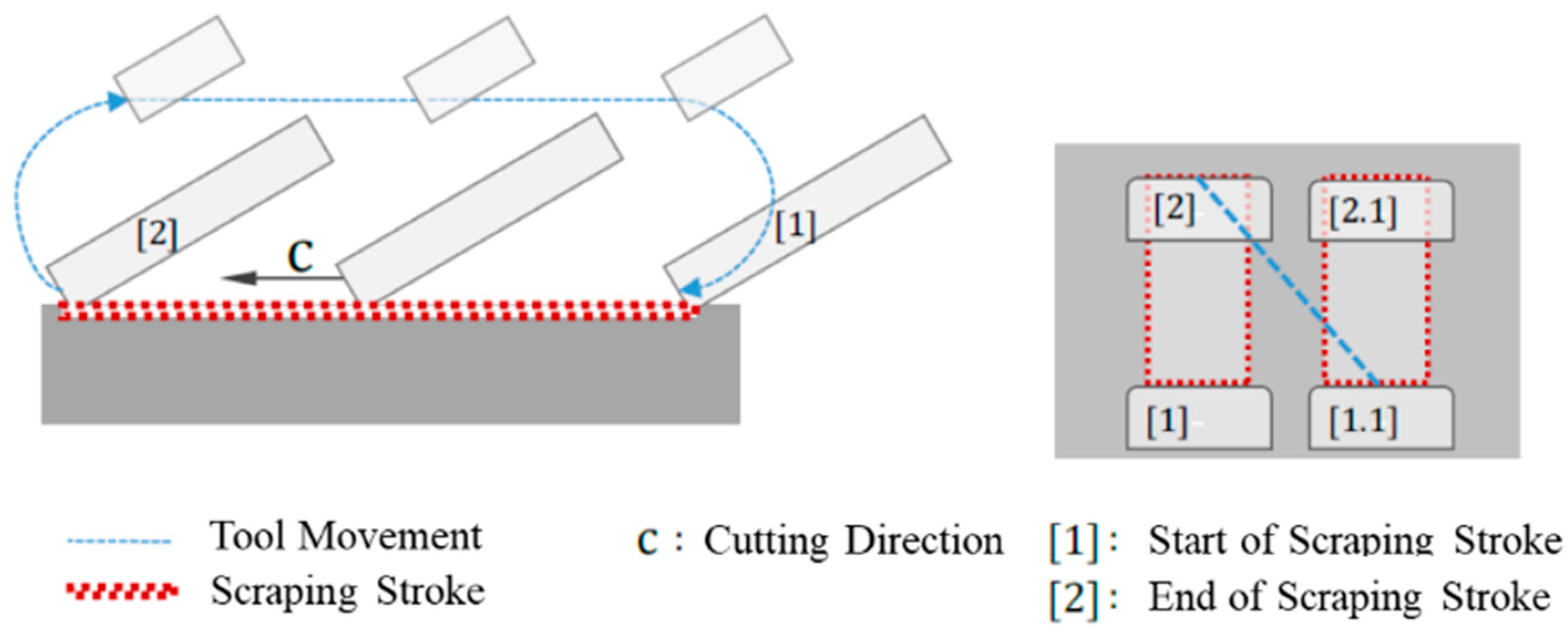
1.2. Characteristics of Hand Scraping

Cutting in hand scraping takes place in individual scraping strokes, which are placed next to each other by the worker during the backstroke, as depicted in Figure 1.
Similar to other cutting processes, hand scraping can be described by characteristic angles and forces. These are summarized in Figure 2, following the general nomenclature for cutting processes according to ISO 3002 and Schmid [9].

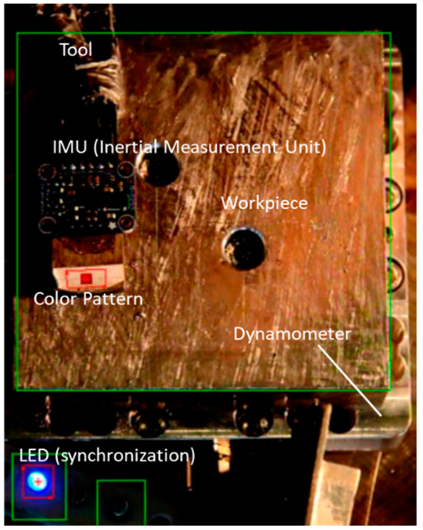
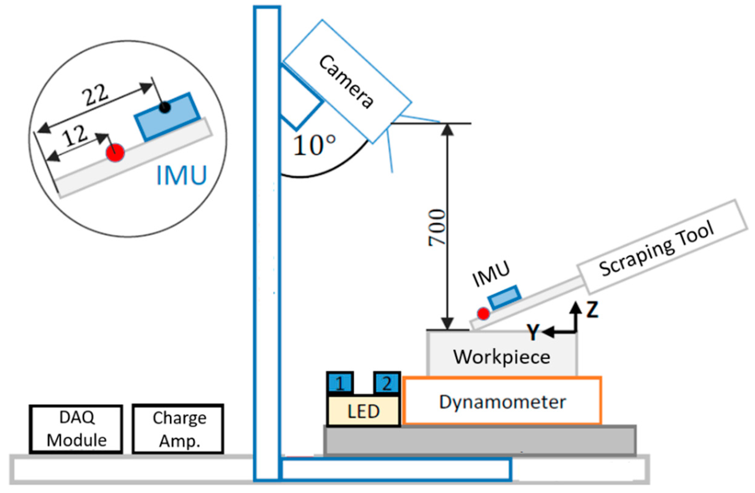
2. Materials and Methods

Measurements were carried out with the help of an extremely experienced worker who has been scraping on a daily basis for more than 30 years. A sketch of the test stand is shown in Figure 3. It consists of the following sensors. A camera is positioned on a stand above the workpiece at an angle of 10° in order to prevent the field of view being covered by the worker while scraping. Its purpose is to capture the position in the X- and Y-direction of the tool. A three-axes dynamometer was installed to register the components of the cutting force (FCX and FCY), as well as of the passive force FP. It is positioned under the workpiece. Finally, an inertial measurement unit (IMU) is attached to the scraping tool to measure its “absolute” orientation in the directional angle δ, the clearence αe, and the tilt angle ε. Two light emitting diodes (LED) serve as triggers and condition indicators. Their status is captured by the camera and processed by software. The signals of the dynamometer and the IMU were acquired by a data acquisition (DAQ) system, which also controlled the LEDs and thus later allowed to synchronize its data with the video data of the camera.
The workpiece had a size of 100 × 100 mm. As workpiece material, cast iron (EN-GJL-250/0.6025) was chosen, being one of the most relevant materials for scraping. Prior to scraping, the surface was machined by wire electrical discharge machining (WEDM). The main components of the test stand and their main specifications are listed in Table 1.
The data of the different sensors and the camera were merged and analyzed using LabVIEW® software code. The tool position data were acquired in real time out of the camera video stream using the software function “color pattern matching”. Figure 4 shows the camera view during a measurement.

3. Results and Discussion

The following results show the first scraping cut of the workpiece. A photograph of the surface after scraping is shown in Figure 5a. It shows the typical visual appearance of scraped surfaces. A section of the workpiece was measured by a 3D profilometer. The results are depicted in Figure 4b.
In the surface scan, several scraping strokes can be recognized as indentations, going from bottom left to top right at an angle of about 30°. Cutting grooves can be recognized along the strokes. At the end of a stroke, often a burr remains perpendicularly to the cutting direction, appearing as bright lines in the diagram. Micro blowholes within the cast iron material are visible as dark spots.

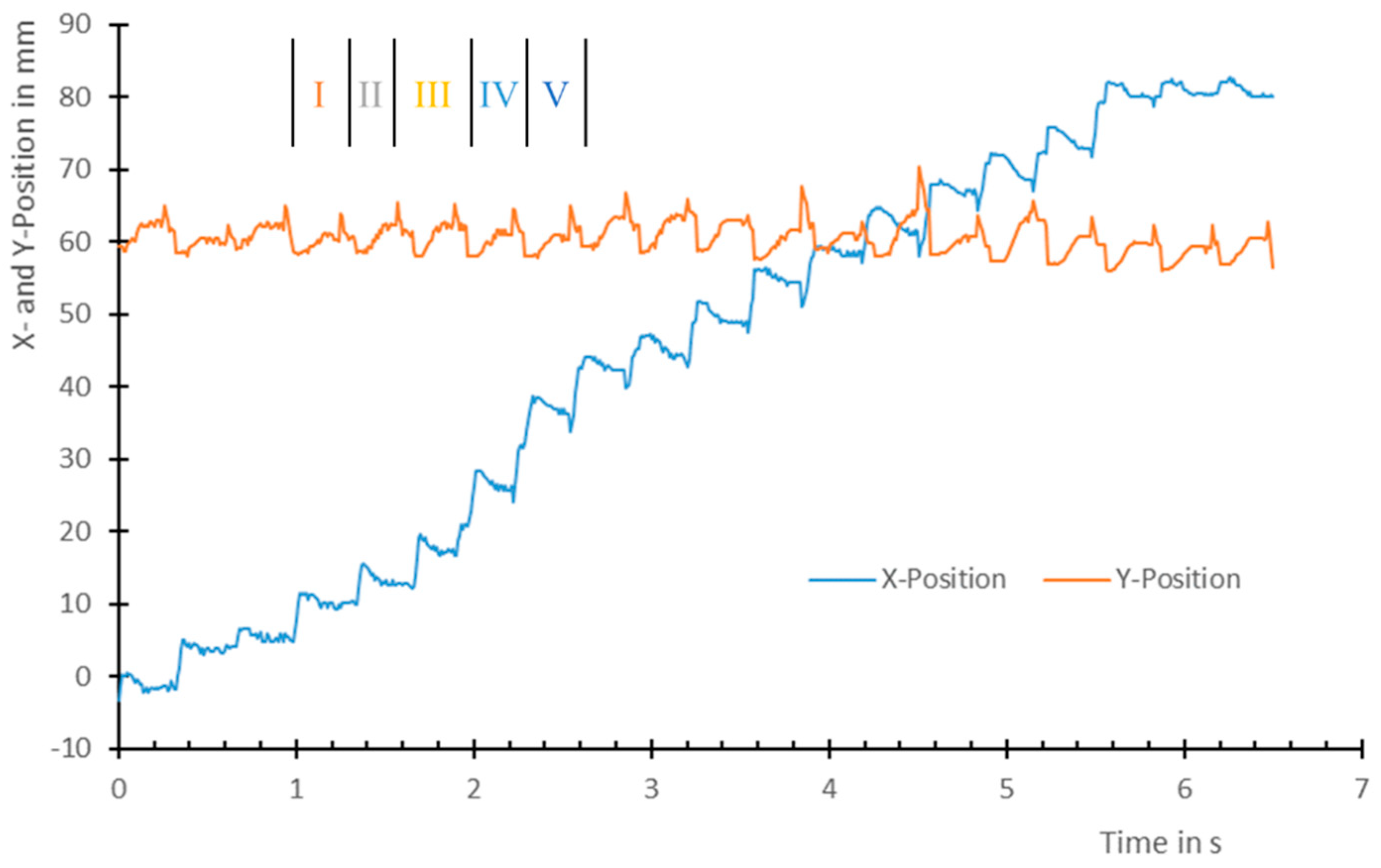
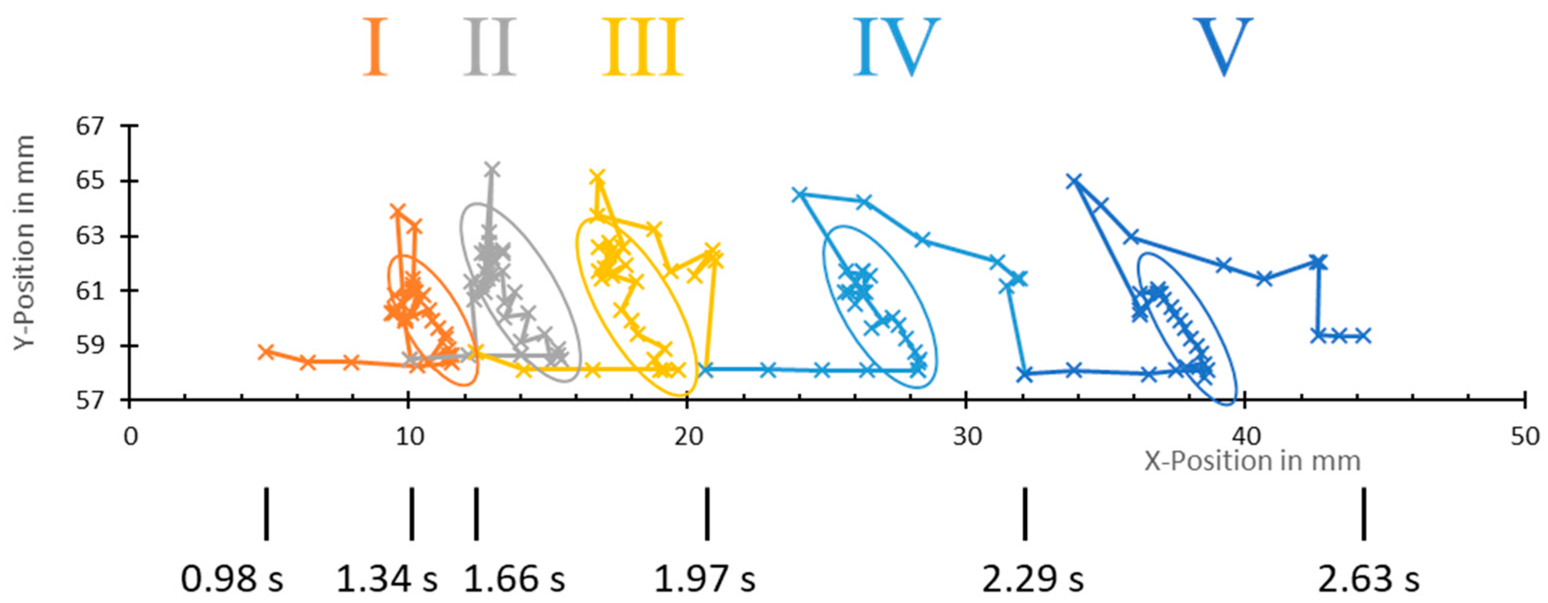
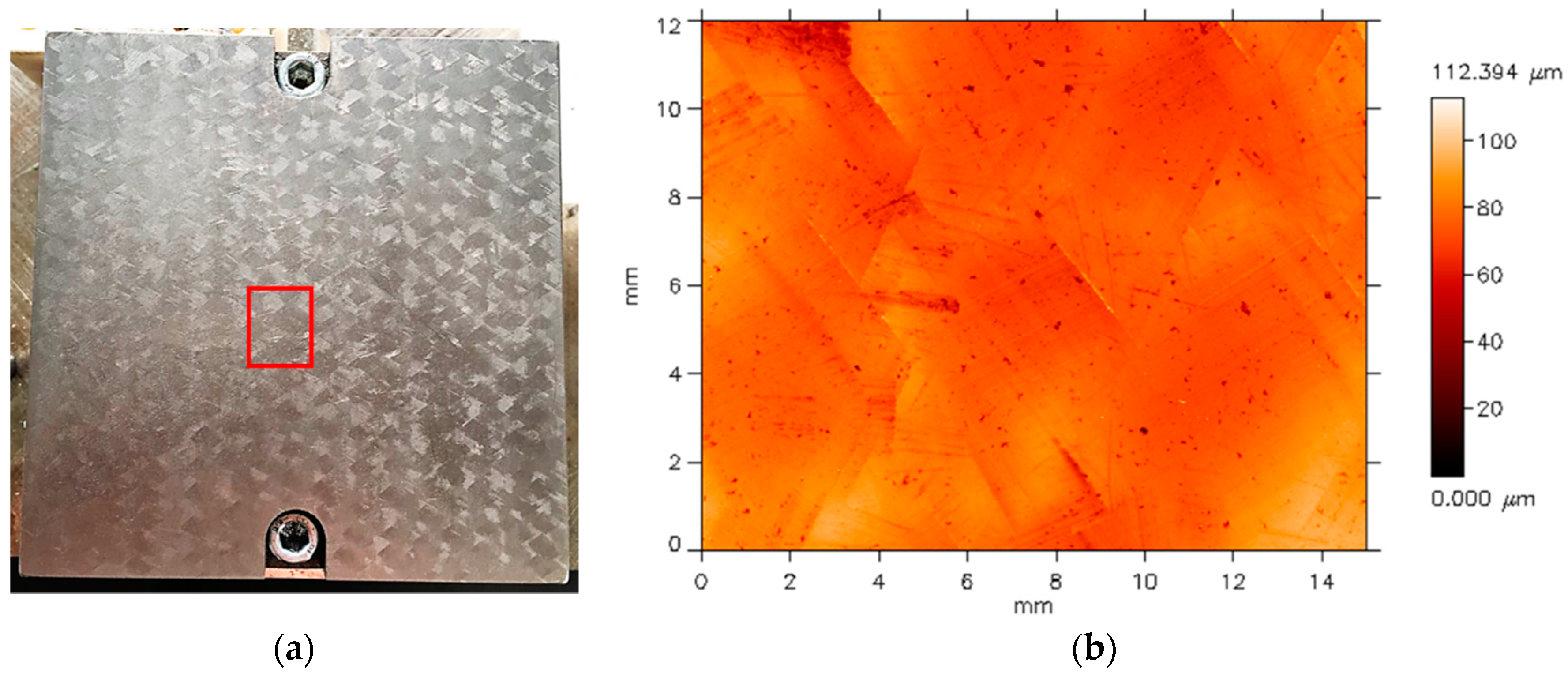
3.1. Movement Analysis

Tool movement in the X- and Y-direction during one line of scraping strokes is depicted in Figure 6. The worker chose to use 20 strokes over the 100 mm. Working with a direction angle δ of approximately 30° scraped parallel to the X-axis effected that all strokes were positioned on roughly the same Y-position while moving over the workpiece in X-direction. The scraping strokes were executed at a rate of approximately 3.1 Hz.
The movement patterns of five consecutive scraping cycles (roman numerals I–V) marked in the chart of Figure 6 are shown in an XY chart in Figure 7. This method allows one to comprehend the actual movement of the tool. The distance between two data points always represents 0.01 s. The scraping strokes as the cutting parts within the cycles are encircled. The diagram reveals that scraping cycles are sometimes executed in a circular manner (I, II) and sometimes without crossing their own paths (III–V). The directional angle δ is reasonably constant, while the length of the strokes varies significantly, as does the feed between two strokes. It can be observed that the tool is being moved in a constant direction even after the stroke, before it is directed to the location of the next stroke. This scraping pattern differs considerably from the kisage scraping process described by Fuji et al. [10].

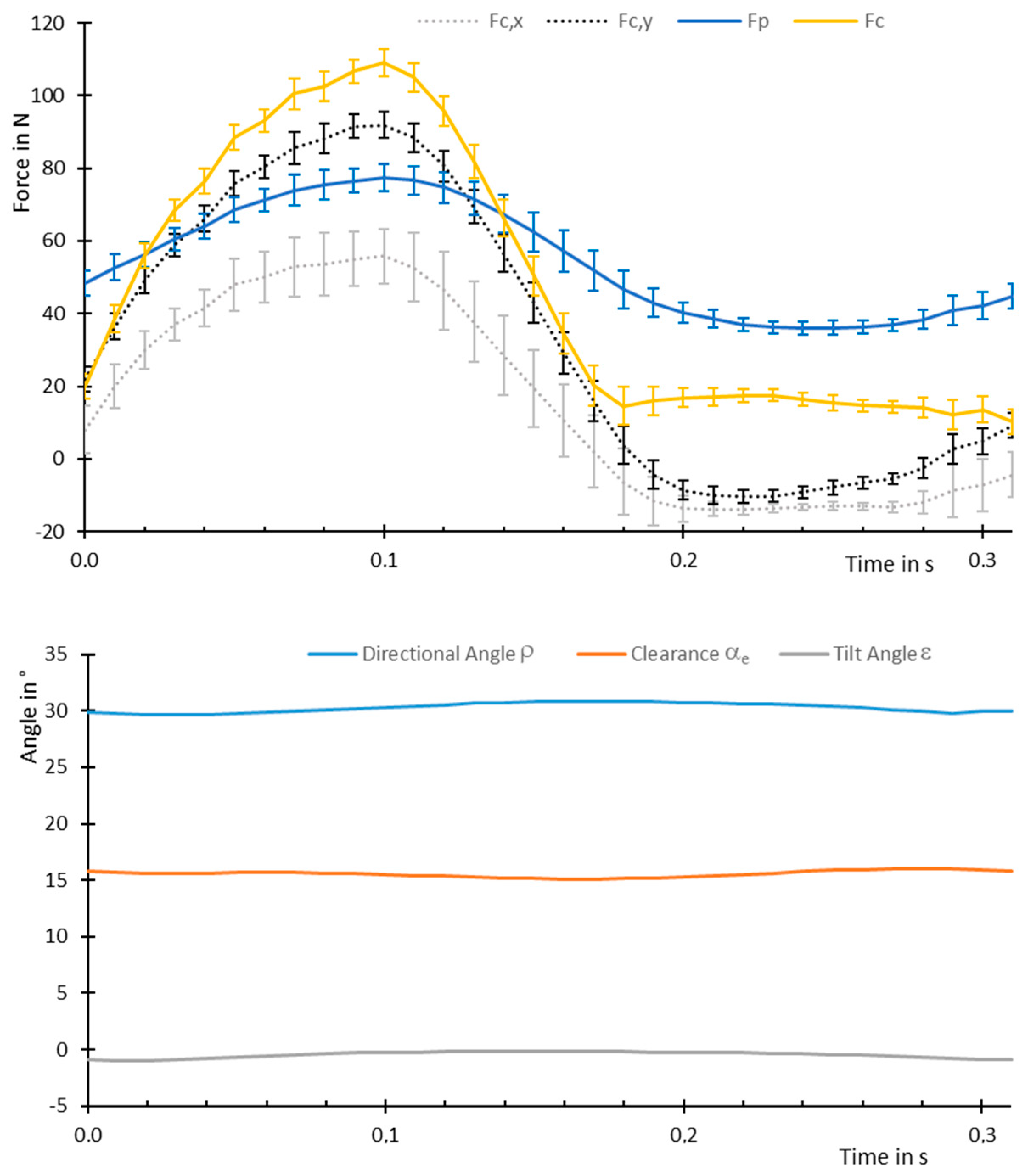
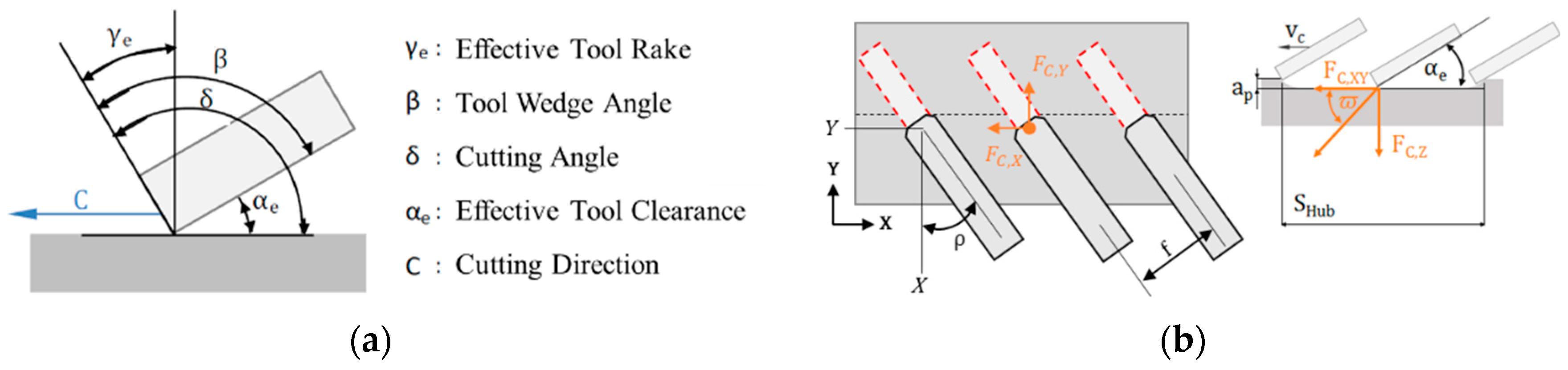
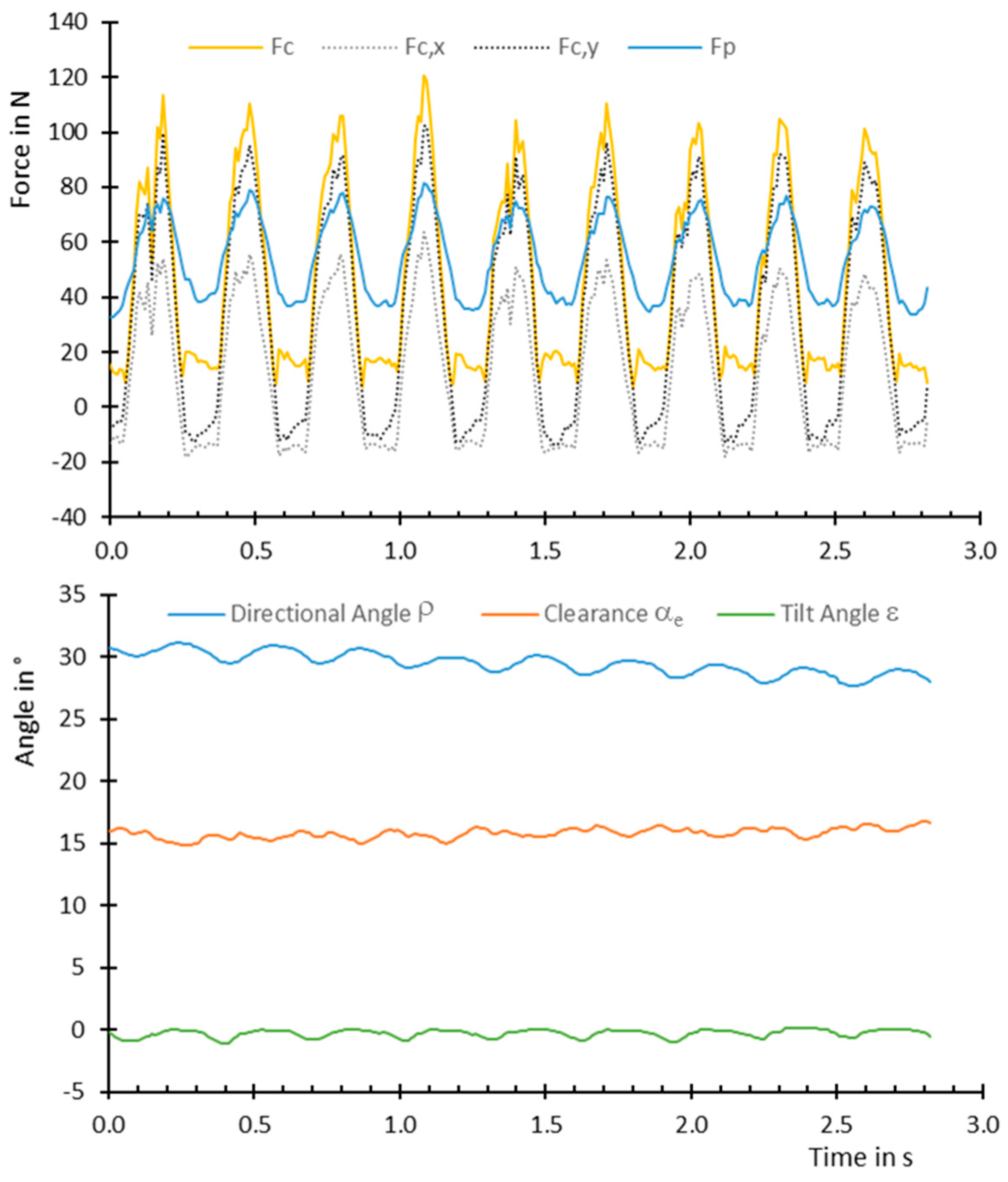
3.2. Force and Orientation Analysis

A measurement of cutting force FC and passive force FP, as well as the tool orientation of nine individual and consecutive scraping cycles, is shown in Figure 8. It can be observed that the passive force FP varies only in a range between approximately 40 N and 80 N, which indicates that the tool is not lifted off the surface during scraping. Also, during the backward stroke, the components of the cutting force FC,X and FC,Y show negative values. The resulting cutting force FC peaks at values around 100 N for every scraping stroke, which is remarkably high for a manual manufacturing process that is executed continuously by the worker. However, the values measured by Fuji et al. [10] reached values up to 300 N in the components (!) of the cutting force during kisage style scraping.
The measurement of the tool orientation reveals that the directional angle δ varies cyclically around 32°, which is considerably less than the value of 45° suggested by Schmid [9]. Also, a slight decrease of δ can be observed, probably because of the changing position of the worker relative to the workpiece over the course of the nine scraping cycles. The clearance αe is held very constant by the worker at values around 16°. The measurement of the tilt angle ε shows only little, yet cyclic deviations of a horizontal tool orientation.
Analogous to Figure 8, average values over 30 scraping cycles are shown in Figure 9. The course of the average cutting force FC and the passive force FP, and specifically the low values of the standard deviations, show a remarkably good repeatability for a manual manufacturing process. The standard deviations of the orientation angles all had values below one degree and thus were not indicated in the diagram. Remarkably, the cyclic effects of the orientation angles almost disappear in the average values.

4. Conclusions

In this research, the “Western” style of hand scraping was analyzed for the first time. The microanalysis revealed the fundamental characteristics of this process, also in comparison with the Japanese kisage hand scraping style. However, because of the fact that only the operation of one worker and only the first cut were measured, more research is required to complement these results. For a complete description of the hand scraping process, a “macroanalysis” of the movement pattern over a whole workpiece and several cuts will also be necessary. In addition, a detailed investigation of the relation between hand scraping and the resulting workpiece surface would be desirable. Together with the development of an appropriate surface measurement technology, automated scraping systems could be implemented.

Author Contributions

K.O. developed the initial idea for this study. I.L. and P.S. designed and implemented the test stand. Y.B. conducted the measurements and their analysis. K.O. wrote the paper, while the co-authors reviewed it.

Funding

This research received no external funding.

Acknowledgments

The authors like to express their gratitude to Kemal Özyildiz for his willingness to contribute to this research as a very experienced hand scraping worker and for sacrificing his time.

Conflicts of Interest

The authors declare no conflict of interest.

References

  1. Whitworth, J. A Paper on Plane Metallic Surfaces or True Planes. In Miscellaneous Papers on Mechanical Subjects; Longman, Brown, Green, Longmans, and Roberts: London, UK, 1858. [Google Scholar]
  2. Oberg, E.; Jones, F. Machinery’s Encyclopedia. Scraping Machine Parts; The Industrial Press: New York, NY, USA, 1917. [Google Scholar]
  3. Tsutsumi, H.; Kyusojin, A.; Fukuda, K. Tribology Characteristics Estimation of Slide-way Surfaces Finished by Scraping. Nippon Kikai Gakkai Ronbunshu C Hen (Trans. Jpn. Soc. Mech. Eng. C) 2018, 2006, 325–331. [Google Scholar]
  4. Ito, Y. Clarification for Essential Features of Scraped Slideway by Step-Land Bearing Model: Conversion of Skilled Craft to Industrial Technology. In Thought-Evoking Approaches in Engineering Problems; Ito, Y., Ed.; Springer International Publishing: Cham, Switzerland, 2014; pp. 277–295. [Google Scholar]
  5. Brinksmeier, E.; Aurich, J.C.; Govekar, E.; Heinzel, C.; Hoffmeister, H.-W.; Klocke, F.; Peters, J.; Rentsch, R.; Stephenson, D.J.; Uhlmann, E.; et al. Advances in Modeling and Simulation of Grinding Processes. CIRP Ann. 2006, 55, 667–696. [Google Scholar] [CrossRef]
  6. Lezanski, P.; Pilacinska, M. The dominance-based rough set approach to cylindrical plunge grinding process diagnosis. J. Intell. Manuf. 2018, 29, 989–1004. [Google Scholar] [CrossRef]
  7. Hashmi, S. Comprehensive Materials Finishing, 1st ed.; Elsevier: Oxford, UK, 2016. [Google Scholar]
  8. Dehghan Ghadikolaei, A.; Vahdati, M. Experimental study on the effect of finishing parameters on surface roughness in magneto-rheological abrasive flow finishing process. Proc. Inst. Mech. Eng. B J. Eng. Manuf. 2014, 229, 1517–1524. [Google Scholar] [CrossRef]
  9. Schmid, W. Schaben. in Günter Spur—Handbuch Spanen (2014); Carl Hanser Verlag GmbH & Co. KG: München, Germany, 2014. [Google Scholar]
  10. Fujii, H.; Shimazu, H.; Lakawathana, P.; Asai, M.; Sase, N.; Kato, T. Analysis of Scraping Process: The Applied Force to and the Movement of the Scaper. In Proceedings of the Twenty-Ninth International Matador Conference, Manchester, UK, 6–7 April 1992; pp. 520–527. [Google Scholar]
  11. Tsutsumi, H.; Yamada, R.; Kyusojin, A.; Nakamura, T. Development of an Automatic Scraping Machine with Recognition for Bearing of Scraped Surfaces—Construction of Automatic Scraping Machine. In Proceedings of the 11th International Conference on Precision Engineering (ICPE), Towards Synthesis of Micro-/Nano-systems, Marrakech, Morocco, 11–16 November 2007; pp. 355–356. [Google Scholar]
  12. Tsutsumi, H.; Yamada, R.; Kyusojin, A.; Nakamura, T. Development of an Automatic Scraping Machine with Recognition for Bearing of Scraped Surfaces—1st Report. J. Jpn. Soc. Precis. Eng. 1996, 62, 219–223. [Google Scholar] [CrossRef]
  13. Tsutsumi, H.; Yamada, R.; Kyusojin, A.; Nakamura, T. Development of an Automatic Scraping Machine with Recognition for Bearing of Scraped Surfaces—3rd Report. J. Jpn. Soc. Precis. Eng. 2005, 71, 358–362. [Google Scholar]
  14. Tong, H.F.; Liu, W.; Chi, Y.; Wang, W. Design of Automatic Scraping System. AMR 2013, 625–630. [Google Scholar] [CrossRef]
  15. Yasuo, Y.; Yin, R.S.; Okamoto, H.; Yamada, M.; Yonezawa, Y.; Narutaki, N. Application of Multi-Joint Type Industrial Robot to Scraping of Surface Plate. J. Jpn. Soc. Precis. Eng. 1989, 55, 1787–1792. [Google Scholar]
  16. Takeuchi, Y.; Sakamoto, M.; Sata, T. Automation of Scraping Works by a Robot Equipped with a CCD Line Sensor and a Contact Detector. CIRP Ann. Manuf. Technol. 1988, 37, 489–492. [Google Scholar] [CrossRef]
  17. Takeuchi, Y.; Sakamoto, M.; Yoshida, T.; Choki, M. The Recognition of Bearings by Means of a CCD Line Sensor and the Automation of Scraping Works. J. Jpn. Soc. Precis. Eng. 1986, 52, 93–98. [Google Scholar] [CrossRef]
  18. Tsai, Y.-C.; Li, J.-H.; Lee, J.-N.; Jywe, W.-Y. Development and Implementation of Automatic Scraping Mechanism. Adv. Sci. Lett. 2012, 8, 211–215. [Google Scholar] [CrossRef]
  19. Li, X.; Sun, L.; Liu, Y. High Points Recognition Method of Scraped Surface Based on Background Subtraction. J. Digit. Inf. Manag. 2013, 11, 115–119. [Google Scholar]
  20. Yamane, Y.; Childs, T. Manufacturing Technology Transfer Chapter 4: Virtual Manufacturin to Speed Up Learning (Scraping). A Japanese Monozukuri View of Needs and Strategies; CRC Press: Boca Raton, FL, USA, 2013. [Google Scholar]
  21. Fan, K.-C.; Torng, J.; Jywe, W.; Chou, R.-C.; Ye, J.-K. 3-D measurement and evaluation of surface texture produced by scraping process. Measurement 2012, 45, 384–392. [Google Scholar] [CrossRef]
  22. Hsieh, T.H.; Jywe, W.Y.; Huang, H.L.; Chen, S.L. Development of a laser-based measurement system for evaluation of the scraping workpiece quality. Opt. Lasers Eng. 2011, 49, 1045–1053. [Google Scholar] [CrossRef]
Figure 1. Tool movement during hand scraping following Schmid [9].
Jmmp 02 00076 g001
Figure 2. Directions, angles (a), and forces (b) of the hand scraping process following ISO 3002 and Schmid [9].
Jmmp 02 00076 g002
Figure 3. Test stand for the microanalysis of hand scraping. IMU—inertial measurement unit; LED—light emitting diodes.
Jmmp 02 00076 g003
Figure 4. Camera image during actual measurement of the hand scraping process.
Jmmp 02 00076 g004
Figure 5. (a) Photograph of the workpiece after scraping (first cut) and (b) 3D surface scan of the workpiece surface (section marked in (a) and rotated by 90° ccw).
Jmmp 02 00076 g005
Figure 6. Movement of the scraping tool during scraping. Roman numerals refer to individual scraping cycles in Figure 7.
Jmmp 02 00076 g006
Figure 7. Movement pattern of five consecutive scraping cycles (numbering cf. Figure 6). Data points were acquired every 0.01 s. Time stamps refer to Figure 6. Encircled parts represent the scraping stroke.
Jmmp 02 00076 g007
Figure 8. Forces and tool orientation of nine consecutive scraping cycles.
Jmmp 02 00076 g008
Figure 9. Average values of forces and tool orientation of 30 scraping cycles. Error bars indicate the standard deviation.
Jmmp 02 00076 g009
Table 1. Measurement equipment applied in the test stand.
SensorTypeMain Specifications
CameraBasler Ace aca1300-200ucFramerate: 150 fps
Resolution: 1280 × 1024
DynamometerME-Systeme Typ K3D120Sensor: strain gauge
Nom. Force in X, Y, & Z: ±500 N
Capture Rate: 100 Hz
Inertial Measurement Unit (IMU)Adafruit BNO055Capture rate: 100 Hz
Max. Sens. Tol. ±4%
Data Acquisition SystemNational Instruments MyRIO40 digital IO
10 analog inputs
6 analog outputs

