Molecular Dynamics Simulation Study of Liquid-Assisted Laser Beam Micromachining Process


Department of Mechanical Engineering, California State University Fullerton, Fullerton, CA 92831, USA
*
Author to whom correspondence should be addressed.
J. Manuf. Mater. Process. 2018, 2(3), 51; https://doi.org/10.3390/jmmp2030051
Submission received: 29 June 2018
/
Revised: 30 July 2018
/
Accepted: 6 August 2018
/
Published: 9 August 2018
(This article belongs to the Special Issue New Findings and Approaches in Machining Processes)
Abstract
:Liquid Assisted Laser Beam Micromachining (LA-LBMM) process is an advanced machining process that can overcome the limitations of traditional laser beam machining processes. This research involves the use of a Molecular Dynamics (MD) simulation technique to investigate the complex and dynamic mechanisms involved in the LA-LBMM process both in static and dynamic mode. The results of the MD simulation are compared with those of Laser Beam Micromachining (LBMM) performed in air. The study revealed that machining during LA-LBMM process showed higher removal compared with LBMM process. The LA-LBMM process in dynamic mode showed lesser material removal compared with the static mode as the flowing water carrying the heat away from the machining zone. Investigation of the material removal mechanism revealed the presence of a thermal blanket and a bubble formation in the LA-LBMM process, aiding in higher material removal. The findings of this study provide further insights to strengthen the knowledge base of laser beam micromachining technology.
1. Introduction
The Laser Beam Micromachining (LBMM) process is a non-traditional technique that is capable of machining a wide range of materials with ultraprecision in a short period [1]. The LBMM process offers several advantages including high resolution, minimum wastage, ease-of-control, repeatability and reproducibility [1]. This process finds application in several fields from micromechanics to microfluidics [2,3]. The LBMM process uses focused thermal energy with high temperatures to remove material from the substrates through melting and vaporization [4]. The LBMM process that is performed in the air results in the formation of Heat Affected Zones (HAZ), which is one of the significant limitations of the process [5]. Also, LBMM process causes other undesired effects including tapered kerf formation, high surface roughness, micro-crack formation, and recast and re-deposition of molten material [5,6]. Additionally, there are possibilities for the amorphization of supercooled liquid along with the recrystallization of the amorphous phase during the LBMM process [7,8]. Performing the LBMM process in a liquid medium is a potential approach to overcome these limitations of the LBMM process [9]. The process known as Liquid-Assisted Laser Beam Micromachining (LA-LBMM) is capable of micromachining materials with features ranging from 100 to 500 μm with reduced thermal damage, with relatively narrow kerf width, and a reduced re-deposition of debris [10,11].
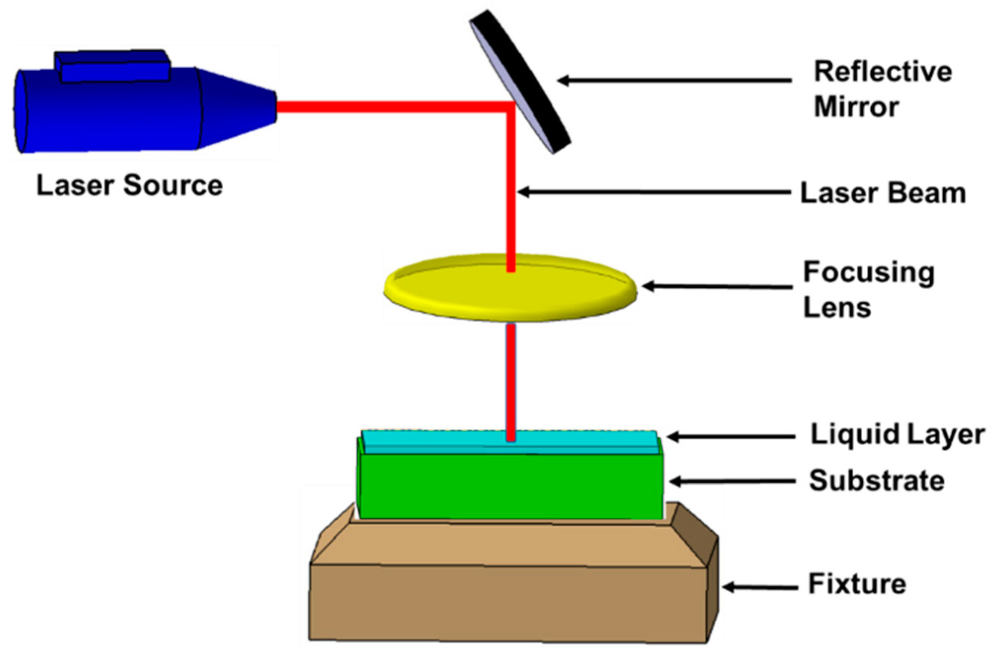
During the LA-LBMM process, the substrate to be machined is submerged entirely in a liquid medium having a thickness of 2–3 mm [12]. The schematic of the LA-LBMM process is shown in Figure 1. The LA-LBMM process can be performed both in static mode (still water) and dynamic mode (flowing water) [13]. Studies have reported that the liquid layer helps in cooling the workpiece, which minimizes the HAZ formation during the machining process [10,11,13,14]. During static mode, the molten debris re-deposit on the machined area, which piles up in the center and is removed by subsequent laser energy [13]. During dynamic mode, the flowing water helps to flush the debris away from the machining zone, preventing re-casting and re-deposition, resulting in a smooth surface [13,15]. Several liquid mediums have been used during the LA-LBMM process including water, ethylene glycol, methanol, and propanol [16,17]. However, the most preferred liquid medium is pure water, as it is environmentally friendly and a low-cost option [12]. It has been reported that the LA-LBMM process can provide higher material removal rates owing to shockwaves and cavitation that helps faster material ejection [18].
It is evident that LA-LBMM is an improved process that addresses some of the critical issues of the LBMM process. However, it is critical to understand the role of liquid medium and the material removal mechanisms involved in the LA-LBMM process to make this process commercially relevant. Experimental studies fail to provide a clear understanding of the material removal mechanisms involved in the LA-LBMM process considering the complexities and dynamic nature of the process at the micron scale. In the past, the finite element analysis (FEA) technique is used to understand the mechanisms involved in the LA-LBMM process [10,19]. One study used FEA tool ANSYS and found that the liquid medium significantly reduced the HAZ for sub-millimeter thick water film [10]. Another study used the finite element modeling technique and Smooth Particle Hydrodynamic (SPH) modeling technique to study CO2 laser underwater machining and reported that the liquid medium helped to reduce surface defects including recast layer and heat damages [19]. The finite difference method (FDM) was used to study the hybrid laser-water jet micro-grooving process on the silicon substrates [20]. The study showed that introducing high-pressure waterjets during the laser machining process helps remove materials in the soft-solid form below its melting temperature.
The LA-LBMM process involves several interactions between the laser beam, substrate, water molecules and the debris particles. While finite element simulation techniques can provide information on the temperature distribution and substrate deformation, further investigations are needed to understand the exact role of water medium along with the underlying complexities and dynamic interactions involved in the LA-LBMM process. Molecular Dynamics (MD) simulation technique is used as a useful tool in the past to understand the molecular level interaction during laser ablation processes [21,22,23]. The MD simulation study of ultrashort laser ablation process revealed that the material removal happens due to thermo-elastic stress developed through thermal heating. It results in ablation of the substrate materials resulting in the formation of clusters of varying sizes [21]. MD simulation technique is also used to study the effect of water on nanoparticle generation during the laser ablation of metal foils [24]. The study found that nanoparticle formation happens due to nucleation and growth of molten metal by rapid cooling in the metal-water mixing environment. The study also reported an extremely high cooling rate of approximately 1012 K/s during the interaction of the growing nanoparticles and water [24]. MD simulation study was used to understand the ablation process of silicon by water-jet-guided laser [25]. The study showed that water cooling helps in minimizing the thermal-affected zones and the substrate maintained its original structure.
The present study uses the MD simulation technique to investigate the underlying process mechanisms involved in the LA-LBMM process in both static and dynamic mode. The study also investigates the effects of laser heat flux on the quality and size of the machined cavity for two different substrate materials—Copper and Silicon Carbide. The study evaluates the machined cavity dimensions and amount of material removed during the LBMM process and LA-LBMM process (both static and dynamic mode).
2. Molecular Dynamics Simulation
In this study, the MD simulation of the LBMM and LA-LBMM process is performed using a “Large-scale atomic/molecular massively parallel simulator” (LAMMPS) [26]. For the LA-LBMM process, water molecules are added above the substrate surface. For the LBMM process, no water molecules are added to the system. The simulation system consists of a substrate having a size of 80 Å × 82 Å × 30 Å and is filled with Newtonian atoms. The copper (Cu) substrate consists of approximately 40,000 Cu atoms initially arranged in a face-centered cubic lattice structure with a lattice constant of 3.61 Å. The Silicon Carbide (SiC) substrate consists of approximately 9000 Si and 9000 carbon atoms initially arranged in a diamond lattice structure with a lattice constant of 4.3596 Å. The substrates are initially given a temperature of 293 K. A fixed layer having a thickness of 3 Å envelopes all the sides of the substrate except the top surface to prevent any undesired movement of the substrate. A thin layer (2 Å) of thermostat atoms is provided between the Newtonian atoms and the fixed layer. The thermostat atoms are kept at 293 K and are used to ensure consistent heat conduction away from the laser heat affected region.
For the LA-LBMM process, the substrate is placed below an equilibrated system of water molecules. For this study, 9000 water molecules are considered including 18,000 hydrogen atoms and 9000 oxygen atoms in the form of a block having a thickness of 30 Å. Periodic boundary conditions are considered in this study considering the extremely small size of the simulation model compared to the experimental conditions. The periodic boundary conditions are maintained on all the atoms along the X and Y directions so that the simulation box is replicated throughout the space to form an infinite lattice that effectively eliminates the spurious size effects of the isolated system. The oxidation phenomena during the laser micromachining process is not considered in the present MD study. The schematic representation of the MD simulation models used to study LBMM and LA-LBMM processes for copper substrates are shown in Figure 2 and Figure 3, respectively. Figure 4 shows the MD simulation models used to study LBMM process for silicon carbide substrate.
The laser beam is simulated using a heat source within a spherical region at the top surface of the substrate having a radius of 8 Å. Atomistic temperature distribution in the substrate is calculated using the equation below to understand the variation in temperature during the LBMM and LA-LBMM processes,
where T is the atomistic temperature, N is the number of atoms; KB is the Boltzmann constant and Ke is the total kinetic energy of the group of atoms. The LA-LBMM and LBMM process simulation is conducted for a duration of 1 picosecond (ps). The simulation model assumes that a single laser heating event is a good understanding of the complex phenomenon of material removal during the laser beam machining process. The process parameter used for the MD simulation study is laser heat flux (or laser heat intensity), which is the rate of heat addition. The unit of laser heat flux used in this study is in energy/time units—Kcal/mol/fs. The effect of percussive laser beam heating is not considered in this study. Additionally, it is assumed that the substrates have uniform and constant thermal properties. The aspect of laser wavelength on the material removal is not considered in this study. Also, quantitative calculation of surface roughness is not performed in this study as the lengths scales of MD simulation and experiments are significantly different.
The interatomic forces between the Cu-Cu atoms in the Cu substrate are calculated using Embedded Atom Method (EAM) model function [27]. The potential energy of an atom using EAM model, is given by
where and label the atoms in the solid, is the distance between atoms and , and is the electron density at the position of atom due to all other atoms in the solid. It is supposed that this density can be given as a sum of individual atomic densities where is the potential function, is the electron charge density from atom of type β at the location of atom i and F is an embedding function that represents the energy required to place atom i of type α into the electron cloud.
The interatomic forces between the Si-C, Si-Si and C-C atoms in the SiC substrate are calculated using Tersoff many-body potential, a suitable potential for the simulations of covalent bonding materials like silicon and carbon [28]. The energy E, between any two neighboring atoms i and j, is given by
The extended simple point charge (SPC/E) model of liquid water is used to describe the water molecules. The water molecule is modeled as a rigid isosceles triangle, having charges situated on each of the three atoms—a positive charge on two hydrogen atoms and an excess negative charge on one oxygen atom. The water molecules interact via the standard Lennard–Jones (LJ) potential [29]. The potential energy in the LJ potential function is calculated as
where σ is the distance at which the two particles are at equilibrium, ε is the strength of the interaction, and r is the distance between the particles. The parameters have different constant values for different interacting particles. The LJ potential is applied to describe the Cu-O and the Cu-H potential energy for water-copper interactions. The Si-O and the C-O potential energy for water-silicon and water-carbon interactions are also described using the LJ potential. The cutoff distances used are 9.8 Å for O-O interactions, 5 Å for Cu-O and Cu-H interactions, 7 Å for C-O interactions, 10 Å for Si-O interactions and 10 Å for all other interactions. The detailed parameters and values for all LJ interaction pairs are listed in Table 1.
The Velocity–Verlet algorithm is employed to calculate the position and velocity of the atoms. The conditions used for simulation of LBMM and LA-LBMM processes are shown in Table 2. Validation of the MD simulation model through experimentation is beyond the scope of this study.
3. Results and Discussion
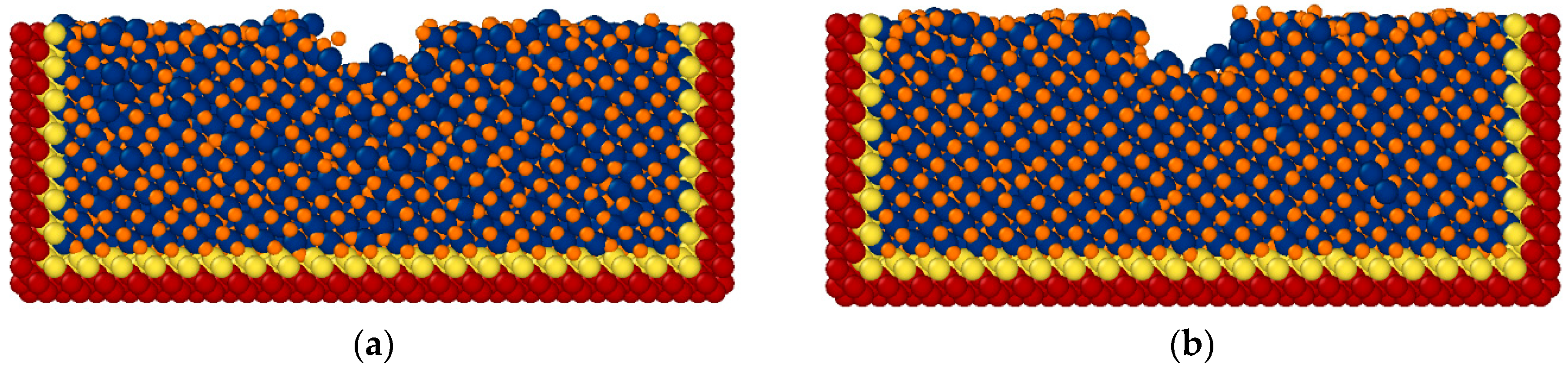
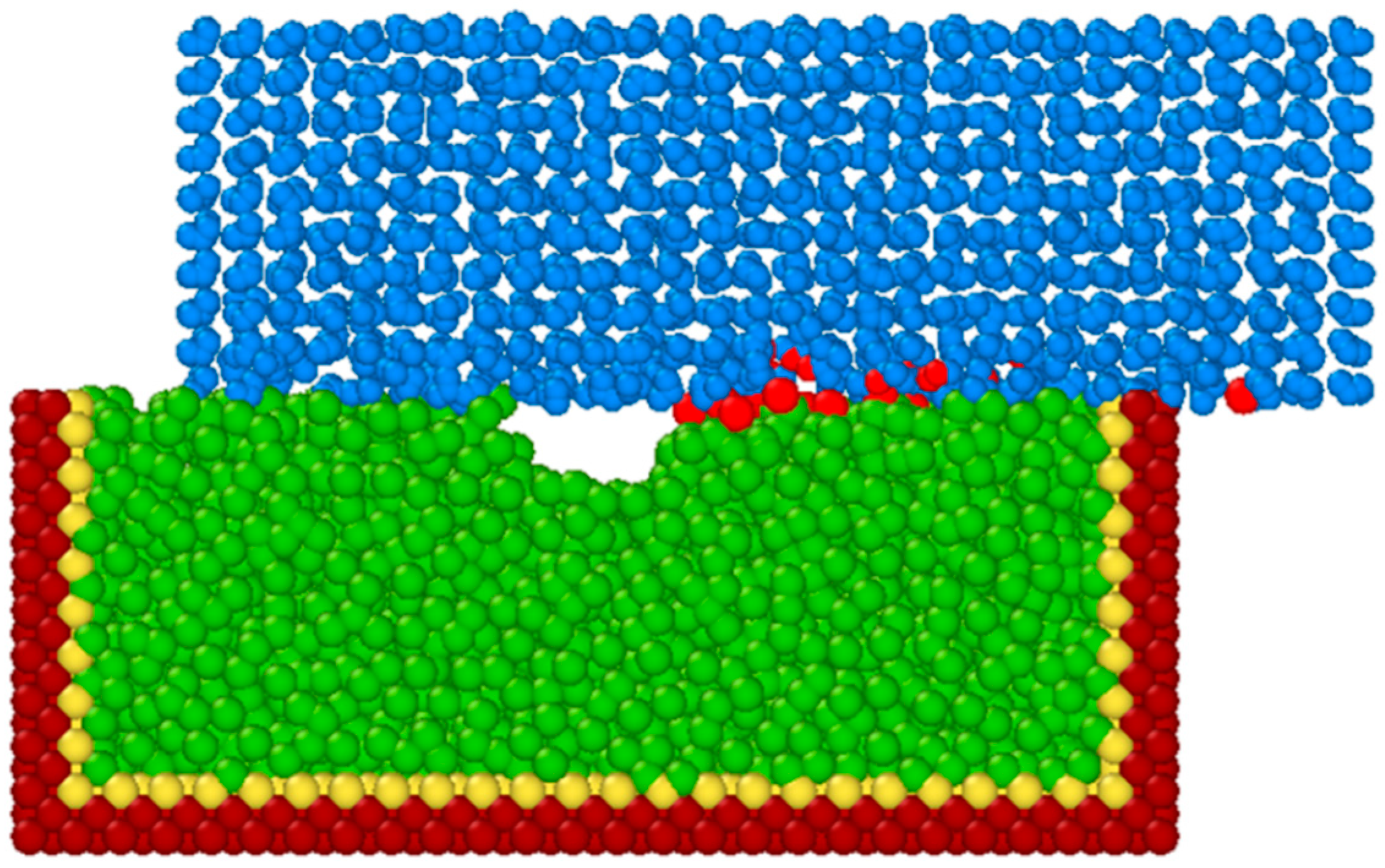
Figure 5 shows a representative atomic configuration of the Cu substrates machined during the LBMM and LA-LBMM processes using a laser heat flux value of 3000 kcal/mol/fs for a simulation duration of 1 ps. In this case, the LA-LBMM is performed in static mode. During LBMM and LA-LBMM processes, the Cu substrate material is removed through both melting and vaporization. In this study, the melting and vaporization points of Cu material is considered as 1358 K and 2835 K, respectively. From the figure, it is seen that machining during the LA-LBMM process results in larger cavity compared to that of the LBMM process.
Figure 6 shows a representative atomic configuration of the SiC substrates machined during the LBMM and LA-LBMM processes (static mode) using a laser heat flux value of 3000 kcal/mol/fs for a simulation duration of 1 ps. The SiC material is primarily removed through the ablation process, and the threshold temperature for ablation is considered as 2973 K. A similar trend is observed as in the case of Cu machining where the LA-LBMM process machined larger cavity compared to that of LBMM process.
3.1. Effect of Laser Power on Cavity Size during LBMM and LA-LBMM Process
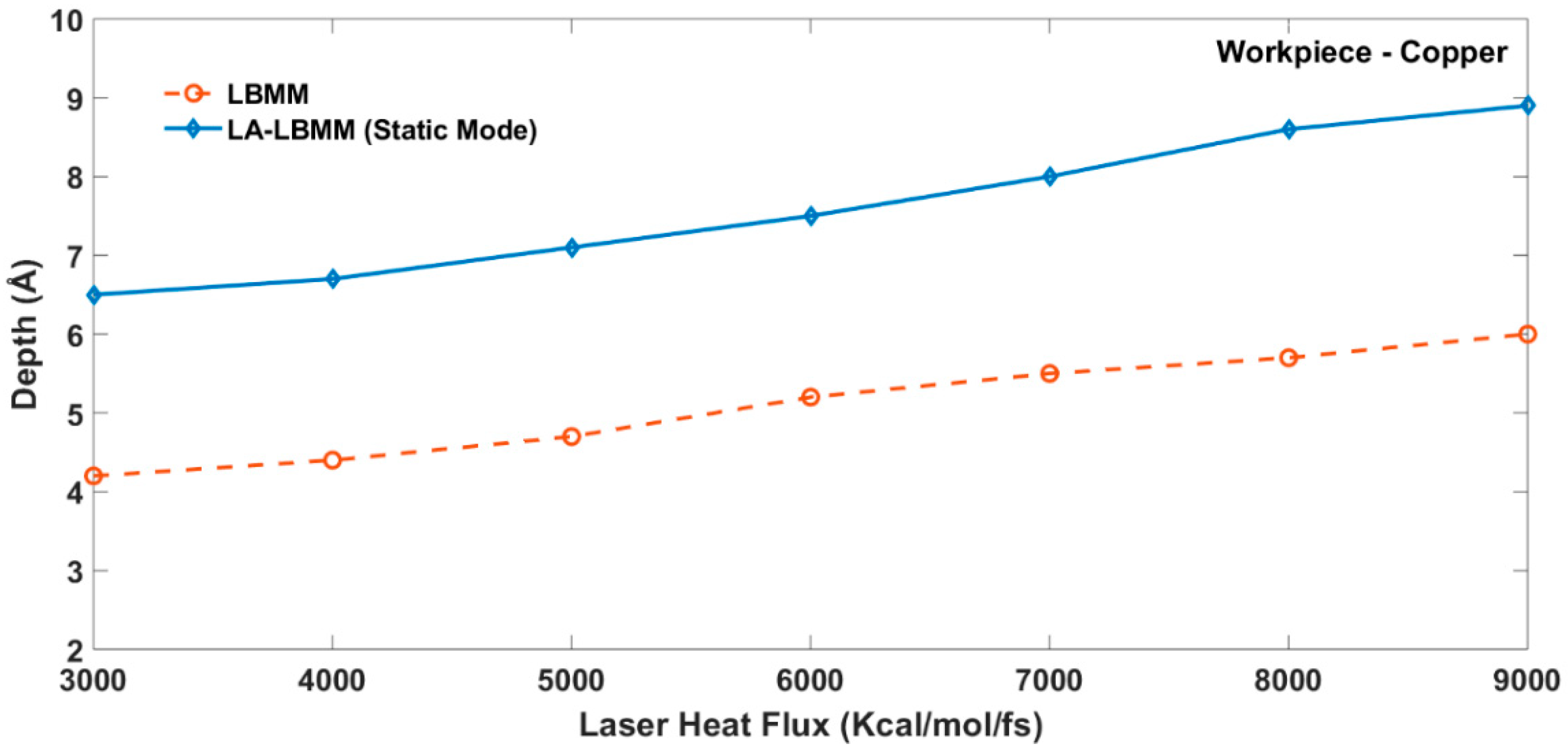
Figure 7 shows the variation in cavity depth with respect to different heat flux for both the LBMM and LA-LBMM process in static mode. It is seen that the depth of the cavities machined increases as the laser heat flux is increased. The depth of the cavity in LA-LBMM process is relatively larger than that in the air for the corresponding laser heat flux. It can be explained by the fact that during the LA-LBMM machining under static water conditions, the thermal energy of the vaporized atoms remains in the machining zone for a longer duration causing more material to be removed. The vaporized molecules move slowly due to the presence of water molecules above the substrate. Figure 8 shows the MD simulation snapshot of the cavity machined on Cu substrate using the LA-LBMM process. In the figure, the red colored atoms represent the molten and vaporized Cu substrate, and the black colored atoms represent the superheated water vapor molecules. In the case of the LBMM process, the copper atoms are vaporized and move away from the machining zone with higher velocity. Moreover, the molten materials tend to redeposit on the surface during the LBMM case. During the LA-LBMM process, the molten material cools when it comes in contact with water causing solidification, which prevents its re-deposition.
The variation in cavity depth with respect to the varying heat flux for the LBMM and LA-LBMM process in static mode on a SiC workpiece is shown in Figure 9. It is seen that the machining depth is higher in the case of the LA-LBMM process compared with that of LBMM process. However, the depth of machining for SiC is relatively lower than that of the Cu substrate. It can be explained by the fact that the SiC material underwent material removal in the form of sublimation at a relatively higher temperate compared to the Cu material.
3.2. Effect of Heat Flux on Number of Atoms Removed during the LBMM and LA-LBMM Process
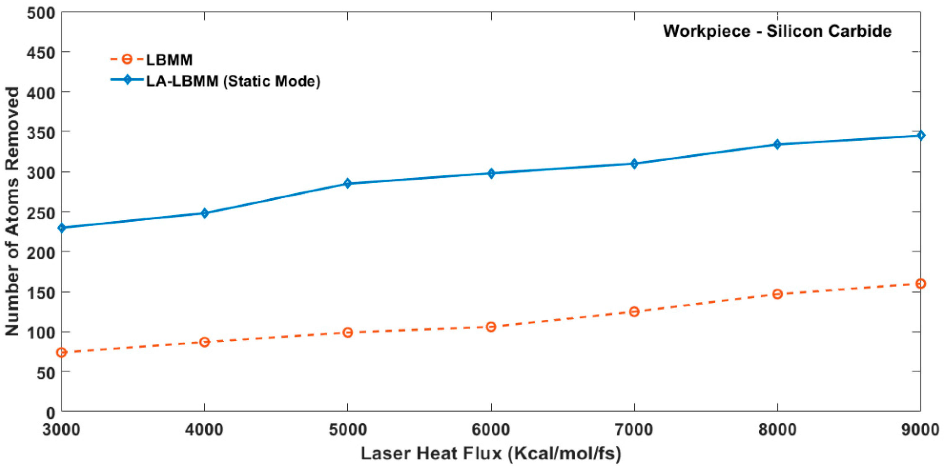
In this study, the number of atoms removed is considered as the atoms whose temperature have exceeded the melting point of the substrate material. Figure 10 and Figure 11 show the variation in the number of atoms removed with respect to the laser heat flux during the LBMM process and LA-LBMM process in static mode for copper and silicon carbide substrates respectively. It is seen that the larger number of atoms are removed in the case of the LA-LBMM process compared with the LBMM process. The increased removal during LA-LBMM can be attributed to the formation of bubbles near the machining zone immediately after the application of laser heat. The bubble formation pushes the liquid away from the machining zone along with the debris. It helps increase the removal of more atoms from the substrate. Moreover, shockwaves are observed during the simulation towards the water layer and also towards the bulk of the substrate. The shockwave, which is moving towards the substrate, causes cracks in the periphery of the cavity. This shockwave is caused due to the rapid heating and cooling of the copper atoms in extremely short duration.
3.3. Comparison between the LA-LBMM Process Static and Dynamic Mode
The MD simulation study is performed to understand the effect of the motion of water above the surface. For this study, a flow velocity of 1000 m/s is provided to the layer of water molecules above the substrate surface. The flow velocity considered in this study is significantly larger than the typical values (of the order of 10 m/s) used during the LA-LBMM experiments. The increased value of flow velocity can be justified by the fact that the mass flow rate of water during the MD simulation is considerably low in the atomistic scales. The increased velocity could compensate for the reduced kinetic energy of the water molecules. Figure 12 shows the snapshot of the MD simulation during the LA-LBMM process for the dynamic mode. In the figure, the red atoms in the figure represent the molten and vaporized Cu substrate atoms while the black atoms represent superheated steam.
The comparison between variations in the number of atoms removed during LA-LBMM for both static and dynamic modes are shown in Figure 13. It is seen that the number of atoms removed from the substrate is relatively less in the dynamic mode compared to static mode. It can be explained because the flowing water carries the heat away from the machining zone, resulting in lesser material removal. Moreover, the cavities have reduced re-deposition during the dynamic mode.
3.4. Process Mechanisms Involved in LA-LBMM Process
The MD simulation study revealed that various mechanisms are involved in the LA-LBMM affecting the material removal process. These mechanisms include (1) Effect of Thermal Blanket (2) Effect of Cavity and Bubble Formation and (3) Effect of Flowing Water Removing Debris. The effect of individual process mechanisms is explained below.
During LA-LBMM in static mode, the water molecules form a barrier to the motion of the vaporized atoms causing their solidification in the liquid. On the other hand, the water molecules carry the debris along with it during the LA-LBMM process in dynamic mode. Both static and dynamic modes showed shockwave propagation through the bulk of the substrate resulting in nanoscale cracking. The water molecules played an essential role in the formation of the bubbles between the cavity surface and water layer.
3.4.1. Effect of Thermal Blanket
During the LA-LBMM process in static mode, the laser heat flux converts the water molecules in the vicinity to superheat steam. The presence of the superheated steam along with the molten and vaporized substrate molecules form a thermal blanket above the machined cavity as shown in Figure 14 (black atoms). The thermal blanket ensures that the machined region remains hot and aids in subsequent material removal. As the time progresses, the superheated steam gradually disperses into the block of water molecules. During the LBMM process, the ablated material is removed from the surface as the laser heat is applied and there is no thermal blanket formation. The presence of the thermal blanket above the machined cavity can be attributed as one of the reasons for larger material removal during the LA-LBMM process as compared to the LBMM process. However, during the LA-LBMM process in dynamic mode the thermal blanket is displaced away from the machining region by the flowing water as shown in Figure 15. This prevents the region to stay warm unlike the machining during static mode. It could provide an explanation for the reduced material removal during the LA-LBMM process in dynamic mode compared to static mode.
3.4.2. Effect of Cavity and Bubble Formation
During the LA-LBMM process in both static and dynamic modes, the removal of atoms from the substrate surface results in the formation of cavities in the water in vicinity of the machined region as shown in Figure 16. The cavities lead to the formation of bubbles of varying sizes. The bursting of the bubbles leads to cavitation and shockwave propagation thorough the substrate resulting in an increased material removal. The bubble formation during LA-LBMM is also witnessed during the experimental studies. Figure 17 shows the presence of bubbles during the LA-LBMM process during the machining of SiC substrates in static mode. The presence of cavities and bubbles in the machined region thus plays a critical role in higher material removal during LA-LBMM process compared with the LBMM process.
3.4.3. Effect of Flowing Water Removing Debris
During the LA-LBMM process in dynamic mode, it is observed that the debris particles of the substrates are removed from the machining area, as shown in Figure 18. The removal of debris plays a critical role during the LA-LBMM process. The removal of debris also helps in achieving a smoother surface after the machining process. However, the debris removal does not happen during the LA-LBMM process in static mode as well as the LBMM process. This means that the LA-LBMM process produces a surface that has better finish compared to the other two processes.
3.5. Validation of MD Simulation Results with Experimentation
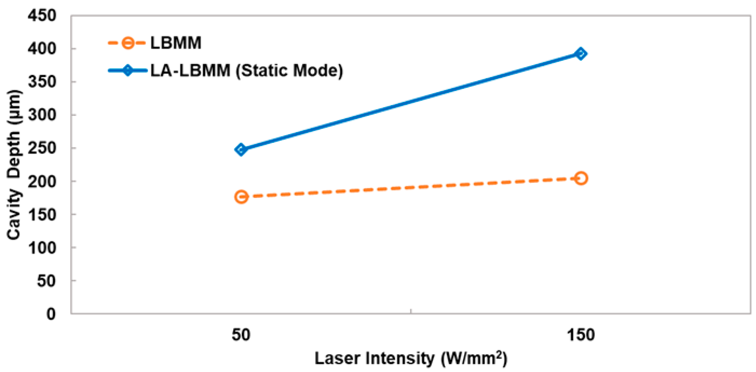
Figure 19 shows the variation in cavity depth during LBMM and LA-LBMM process performed experimentally on borosilicate glass substrates (size 25 mm × 75 mm and 1.2 mm thickness). CO2 laser machine manufactured by Guang Zhou Amonstar Trade Co., Ltd. (Guang Zhou, China) is used for the experimental studies. The intensities of the laser used are 50 W/mm2 and 150 W/mm2. For the experimental results for machining performed under air (LBMM process), maximum cavity depths are seen to be 177 μm and 248 μm for laser power of 10 W and 30 W respectively. The cavity depth values for experimental results for machining performed under thin film of water (LA-LBMM process in static mode with water layer thickness of 0.5 mm) are 205 μm and 393 μm, respectively. This experimental study thus finds that the depth of machining increases with increases in laser power. Additionally, the experimental study also found that the depth is more for the LA-LBMM process compared to the LBMM process. These results are in agreement with the finding of the current MD simulation study.
4. Conclusions
In this study, MD simulation is performed to understand the process mechanism involved in the LA-LBMM process. The effect of laser heat flux on the depth of the machined cavity and the number of atoms removed are studied. A comparison between the machining results obtained during the LA-LBMM process and LBMM process is presented. The effect of water motion on the cavity formation is studied by comparing the LA-LBMM process during static and dynamic modes. An explanation of material removal mechanisms during the LA-LBMM process is presented. The major conclusions derived from this study are as follows:
- The MD simulation study revealed that the cavity machined during the LA-LBMM process is having more depth than that of LBMM process. It is attributed to the fact that the thermal energy is entrapped in the machining zone. The velocity of the vaporized atoms is lower during the LA-LBMM process due to the presence of a layer of water molecules above the substrate;
- The number of atoms removed during LA-LBMM process is found to be significantly higher than that during LBMM process. The LA-LBMM process in dynamic mode showed lesser material removal compared with that of static mode;
- A comparison between the LA-LBMM processes in static and dynamic modes showed the material removal in higher in the case of static mode compared with dynamic mode. However, the surface finish obtained in dynamic mode is better than static mode because of the removal of machining debris;
- The MD simulation study revealed various mechanisms involved in the LA-LBMM process including the formation of a thermal blanket and the formation of cavities and bubbles in the vicinity of the machined region. The LA-LBMM process in dynamic mode suggested the removal of debris from the machining region, leading to reduced re-deposition of molten material on the cavity surface;
- The results of the MD simulation study are consistent with findings of experimental results of both the LBMM and LA-LBMM processes.
Author Contributions
S.J. and V.A.M. conceived and designed the Molecular Dynamics (MD) simulation model. V.A.M. performed the simulations and S.J. interpreted and analyzed the simulation output. Both V.A.M. and S.J. prepared the manuscript together.
Funding
This research received no external funding.
Acknowledgments
Authors would like to thank the College of Engineering and Computer Science at California State University Fullerton for the financial support. The authors would also like to thank Sandia National Laboratories for providing LAMMPS software for this research.
Conflicts of Interest
The authors declare no conflict of interest.
References
- Mishra, S.; Yadava, V. Laser beam micromachining (lbmm)—A review. Opt. Lasers Eng. 2015, 73, 89–122. [Google Scholar] [CrossRef]
- Athanasiou, C.-E.; Bellouard, Y.A. Monolithic micro-tensile tester for investigating silicon dioxide polymorph micromechanics, fabricated and operated using a femtosecond laser. Micromachines 2015, 6, 1365–1386. [Google Scholar] [CrossRef]
- Suriano, R.; Kuznetsov, A.; Eaton, S.M.; Kiyan, R.; Cerullo, G.; Osellame, R.; Chichkov, B.N.; Levi, M.; Turri, S. Femtosecond laser ablation of polymeric substrates for the fabrication of microfluidic channels. Appl. Surf. Sci. 2011, 257, 6243–6250. [Google Scholar] [CrossRef]
- Dubey, A.K.; Yadava, V. Laser beam machining—A review. Int. J. Mach. Tools Manuf. 2008, 48, 609–628. [Google Scholar] [CrossRef]
- Feng, Q.; Picard, Y.; Liu, H.; Yalisove, S.; Mourou, G.; Pollock, T. Femtosecond laser micromachining of a single-crystal superalloy. Scr. Mater. 2005, 53, 511–516. [Google Scholar] [CrossRef]
- Chung, C.K.; Lin, S.L. CO2 laser micromachined crackless through holes of pyrex 7740 glass. Int. J. Mach. Tools Manuf. 2010, 50, 961–968. [Google Scholar] [CrossRef]
- Ghidelli, M.; Gravier, S.; Blandin, J.-J.; Pardoen, T.; Raskin, J.-P.; Mompiou, F. Compositional-induced structural change in ZrxNi100−x thin film metallic glasses. J. Alloys Compd. 2014, 615, S348–S351. [Google Scholar] [CrossRef]
- Peng, C.; Cheng, L.; Mansuripur, M. Experimental and theoretical investigations of laser-induced crystallization and amorphization in phase-change optical recording media. J. Appl. Phys. 1997, 82, 4183–4191. [Google Scholar] [CrossRef]
- Garcia-Giron, A.; Sola, D.; Peña, J. Liquid-assisted laser ablation of advanced ceramics and glass-ceramic materials. Appl. Surf. Sci. 2016, 363, 548–554. [Google Scholar] [CrossRef] [Green Version]
- Mistry, V.; James, S. Finite element analysis and simulation of liquid-assisted laser beam machining process. Int. J. Adv. Manuf. Technol. 2017, 94, 2325–2331. [Google Scholar] [CrossRef]
- Parmar, M.; James, S. Experimental and modeling study of liquid-assisted—Laser beam micromachining of smart ceramic materials. J. Manuf. Mater. Process. 2018, 2, 28. [Google Scholar] [CrossRef]
- Tangwarodomnukun, V.; Likhitangsuwat, P.; Tevinpibanphan, O.; Dumkum, C. Laser ablation of titanium alloy under a thin and flowing water layer. Int. J. Mach. Tools Manuf. 2015, 89, 14–28. [Google Scholar] [CrossRef]
- Alahmari, A.M.; Ahmed, N.; Darwish, S. Laser beam micro-machining under water immersion. Int. J. Adv. Manuf. Technol. 2016, 83, 1671–1681. [Google Scholar] [CrossRef]
- Bharatish, A.; Narasimha Murthy, H.N.; Anand, B.; Madhusoodana, C.D.; Praveena, G.S.; Krishna, M. Characterization of hole circularity and heat affected zone in pulsed CO2 laser drilling of alumina ceramics. Opt. Laser Technol. 2013, 53, 22–32. [Google Scholar] [CrossRef]
- Teixidor, D.; Ferrer, I.; Ciurana, J.; Özel, T. Optimization of process parameters for pulsed laser milling of micro-channels on aisi h13 tool steel. Robot. Comput. Integr. Manuf. 2013, 29, 209–218. [Google Scholar] [CrossRef]
- Ali, N.; Bashir, S.; Akram, M.; Mahmood, K. Effect of dry and wet ambient environment on the pulsed laser ablation of titanium. Appl. Surf. Sci. 2013, 270, 49–57. [Google Scholar] [CrossRef]
- Bashir, S.; Rafique, M.S.; Nathala, C.S.; Husinsky, W. Surface and structural modifications of titanium induced by various pulse energies of a femtosecond laser in liquid and dry environment. Appl. Phys. A 2014, 114, 243–251. [Google Scholar] [CrossRef]
- Gomez-Rosas, G.; Rubio-González, C.; Ocaña, J.; Molpeceres, C.; Porro, J.; Morales, M.; Casillas, F.; Mora-Gonzalez, M.; Peña-Lecona, F. Application of laser shock processing system by underwater irradiation (1064 nm) in metal surface. AIP Conf. Proc. 2008, 992, 1123–1128. [Google Scholar]
- Yan, Y.; Li, L.; Sezer, K.; Wang, W.; Whitehead, D.; Ji, L.; Bao, Y.; Jiang, Y. CO2 laser underwater machining of deep cavities in alumina. J. Eur. Ceram. Soc. 2011, 31, 2793–2807. [Google Scholar] [CrossRef]
- Tangwarodomnukun, V.; Wang, J.; Huang, C.; Zhu, H. Heating and material removal process in hybrid laser-waterjet ablation of silicon substrates. Int. J. Mach. Tools Manuf. 2014, 79, 1–16. [Google Scholar] [CrossRef]
- Nedialkov, N.; Imamova, S.; Atanasov, P.; Berger, P.; Dausinger, F. Mechanism of ultrashort laser ablation of metals: Molecular dynamics simulation. Appl. Surf. Sci. 2005, 247, 243–248. [Google Scholar] [CrossRef]
- Herrmann, R.F.; Gerlach, J.; Campbell, E.E. Molecular dynamics simulation of laser ablation of silicon. Nucl. Instrum. Methods Phys. Res. Sect. B Beam Interact. Mater. Atoms 1997, 122, 401–404. [Google Scholar] [CrossRef]
- Meng, X.; Zhou, J.; Huang, S.; Su, C.; Sheng, J. Properties of a laser shock wave in al-cu alloy under elevated temperatures: A molecular dynamics simulation study. Materials 2017, 10, 73. [Google Scholar] [CrossRef] [PubMed]
- Shih, C.-Y.; Wu, C.; Shugaev, M.V.; Zhigilei, L.V. Atomistic modeling of nanoparticle generation in short pulse laser ablation of thin metal films in water. J. Colloid Interface Sci. 2017, 489, 3–17. [Google Scholar] [CrossRef] [PubMed]
- Zhou, W.; Gong, K.; Wan, J.; Quan, L.; Chu, Y.; Cao, Y. Molecular dynamics simulation study on ablation of silicon by water-jet-guided laser. Proc. Inst. Mech. Eng. Part E J. Process Mech. Eng. 2016, 231, 1217–1225. [Google Scholar] [CrossRef]
- Plimpton, S. Fast parallel algorithms for short-range molecular dynamics. J. Comput. Phys. 1995, 117, 1–19. [Google Scholar] [CrossRef]
- Foiles, S.; Baskes, M.; Daw, M. Embedded-atom-method functions for the fcc metals cu, Ag, Au, Ni, Pd, Pt, and their alloys. Phys. Rev. B 1986, 33, 7983. [Google Scholar] [CrossRef]
- Huang, Z.G.; Guo, Z.N.; Chen, X.; Yue, T.M.; To, S.; Lee, W.B. Molecular dynamics simulation for ultrafine machining. Mater. Manuf. Process. 2006, 21, 393–397. [Google Scholar] [CrossRef]
- Jones, J.E. In On the determination of molecular fields.—II. From the equation of state of a gas. Proc. R. Soc. Lond. A 1924, 106, 463–477. [Google Scholar] [CrossRef]
Figure 1.
Schematic of Liquid-Assisted Laser Beam Machining Process.

Figure 2.
Molecular Dynamics Simulation Model of the Laser Beam Micromachining (LBMM) Process on Copper Substrate (a) Sectional view (b) 3-Dimensional view.
Figure 2.
Molecular Dynamics Simulation Model of the Laser Beam Micromachining (LBMM) Process on Copper Substrate (a) Sectional view (b) 3-Dimensional view.
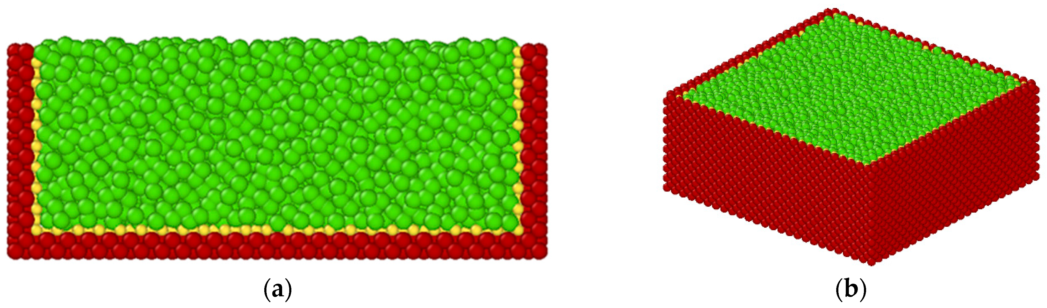
Figure 3.
Molecular Dynamics Simulation Model of the Liquid-Assisted Laser Beam Micromachining (LA-LBMM) Process on Copper Substrate (a) Sectional view (b) 3-Dimensional view.
Figure 3.
Molecular Dynamics Simulation Model of the Liquid-Assisted Laser Beam Micromachining (LA-LBMM) Process on Copper Substrate (a) Sectional view (b) 3-Dimensional view.
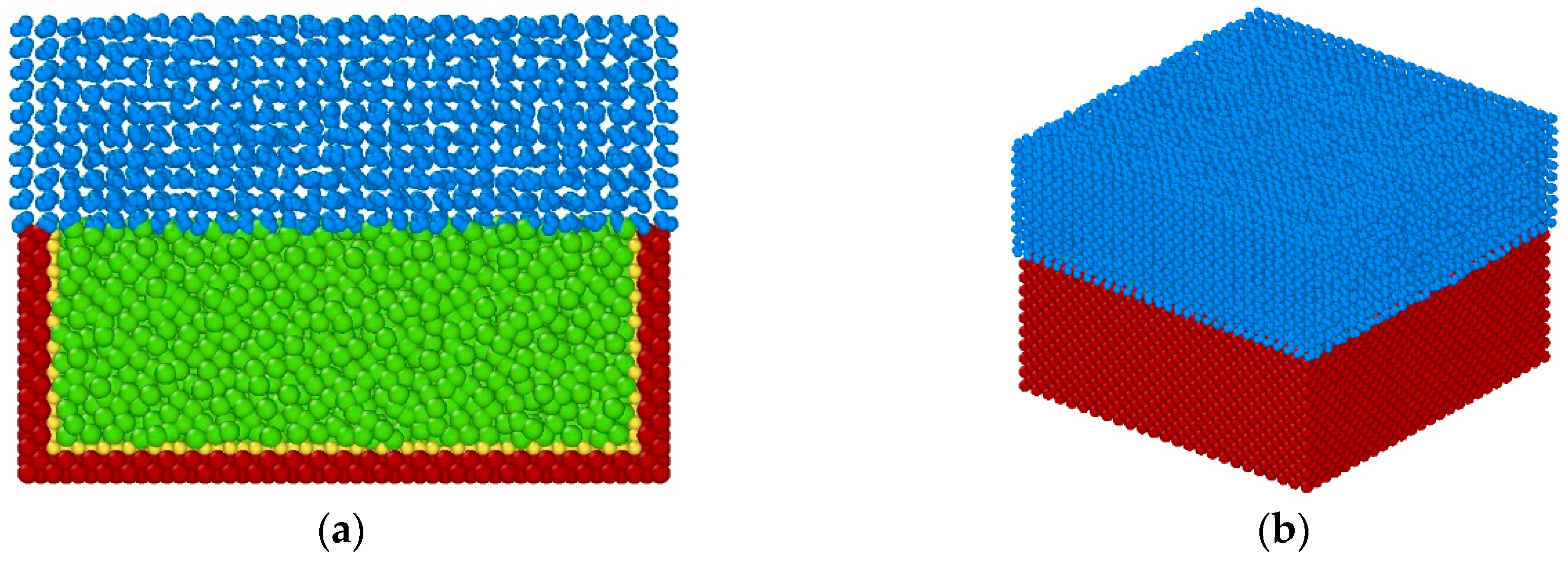
Figure 4.
Molecular Dynamics Simulation Model of the LBMM Process on Silicon Carbide Substrate (a) Sectional view (b) 3-Dimensional view.
Figure 4.
Molecular Dynamics Simulation Model of the LBMM Process on Silicon Carbide Substrate (a) Sectional view (b) 3-Dimensional view.
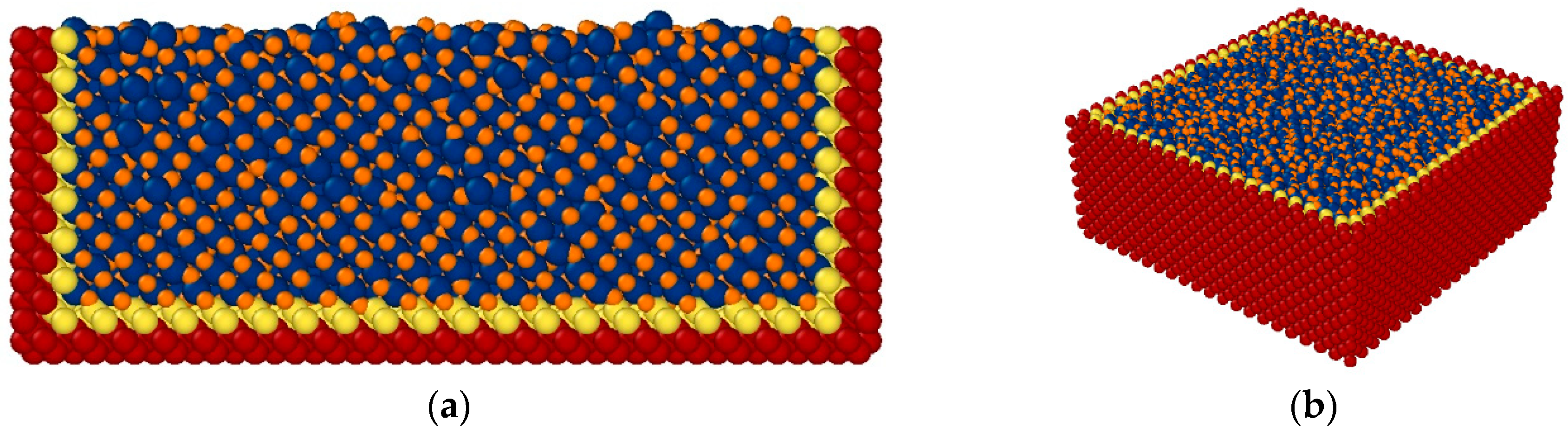
Figure 5.
Molecular Dynamics Simulation Snapshot of Cavity Machined on Cu Substrate during (a) LBMM Process and (b) LA-LBMM Process (Static Mode).
Figure 5.
Molecular Dynamics Simulation Snapshot of Cavity Machined on Cu Substrate during (a) LBMM Process and (b) LA-LBMM Process (Static Mode).
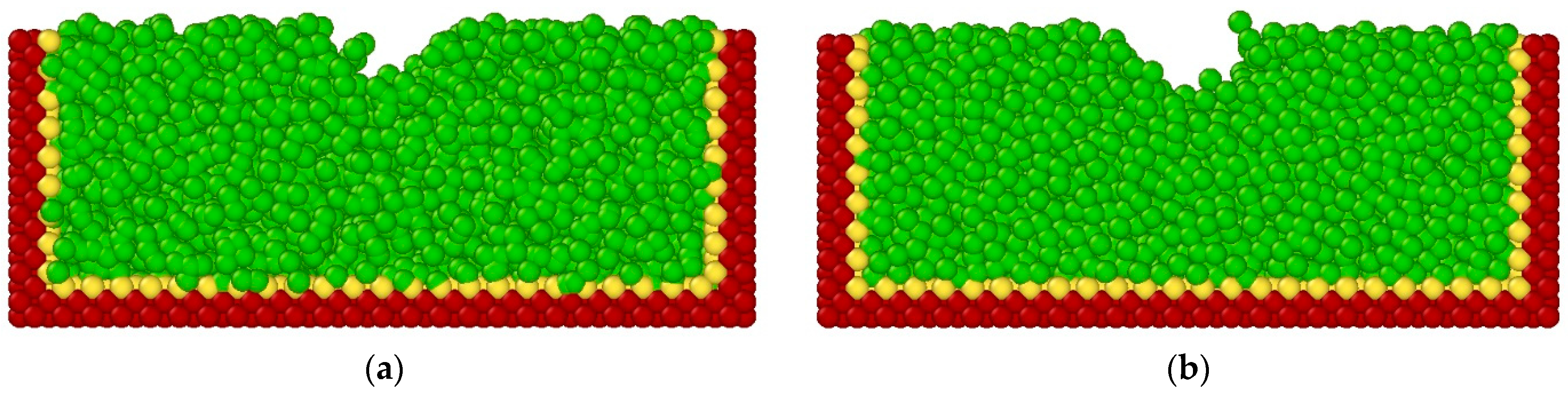
Figure 6.
Molecular Dynamics Simulation Snapshot of Cavity Machined on SiC Substrate during (a) the LBMM Process and (b) LA-LBMM Process (Static Mode).
Figure 6.
Molecular Dynamics Simulation Snapshot of Cavity Machined on SiC Substrate during (a) the LBMM Process and (b) LA-LBMM Process (Static Mode).

Figure 7.
Variation in Cavity Depth with respect to Heat Flux during the LBMM Process and LA-LBMM Process (Static Mode) on Cu Substrate.
Figure 7.
Variation in Cavity Depth with respect to Heat Flux during the LBMM Process and LA-LBMM Process (Static Mode) on Cu Substrate.

Figure 8.
MD Simulation Snapshot of Cavity Machined during LA-LBMM Process (Static Mode).
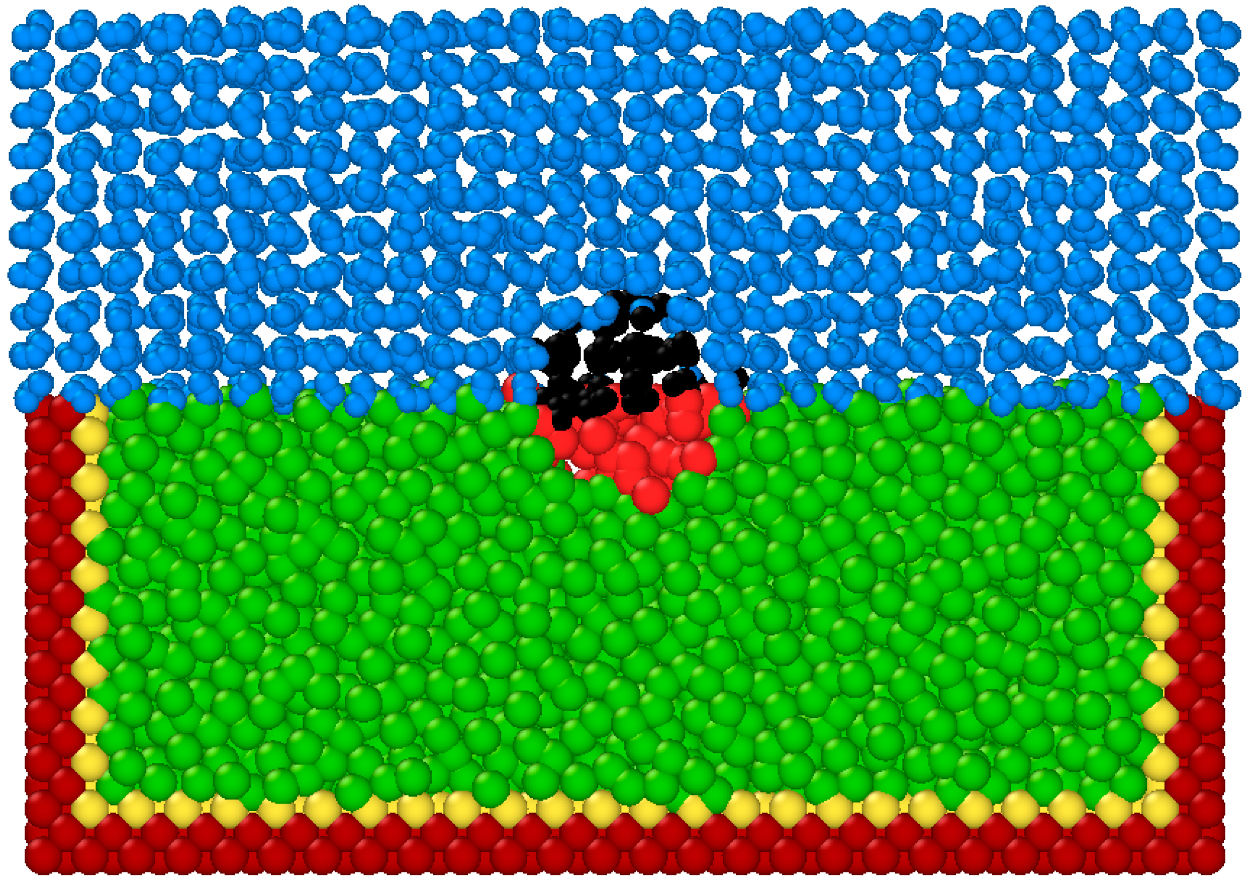
Figure 9.
Variation in Cavity Depth with respect to Heat Flux during the LBMM Process and LA-LBMM Process (Static Mode) on SiC Substrate.
Figure 9.
Variation in Cavity Depth with respect to Heat Flux during the LBMM Process and LA-LBMM Process (Static Mode) on SiC Substrate.
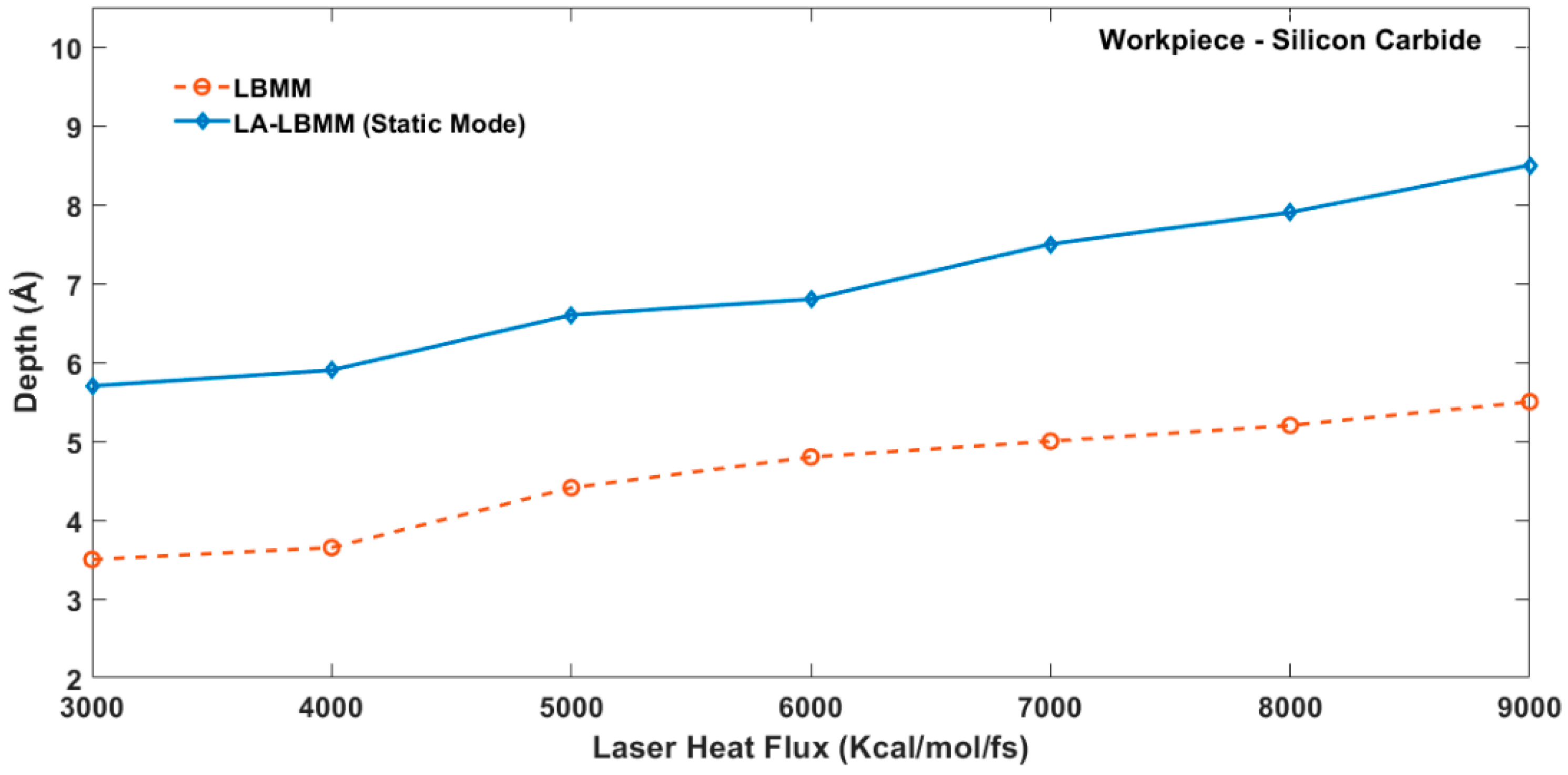
Figure 10.
Variation in Number of Atoms Removed with respect to Heat Flux during LBMM and LA-LBMM Process (Static Mode) on Cu Substrate.
Figure 10.
Variation in Number of Atoms Removed with respect to Heat Flux during LBMM and LA-LBMM Process (Static Mode) on Cu Substrate.
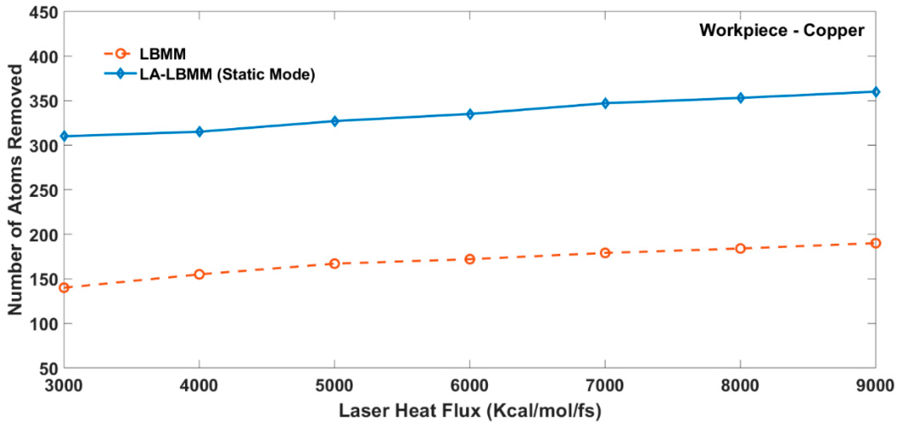
Figure 11.
Variation in the Number of Atoms Removed with respect to the Heat Flux during the LBMM and LA-LBMM Process (Static Mode) on the SiC Substrate.
Figure 11.
Variation in the Number of Atoms Removed with respect to the Heat Flux during the LBMM and LA-LBMM Process (Static Mode) on the SiC Substrate.

Figure 12.
MD Simulation Snapshot of Cavity Machined during the LA-LBMM Process (Dynamic Mode).
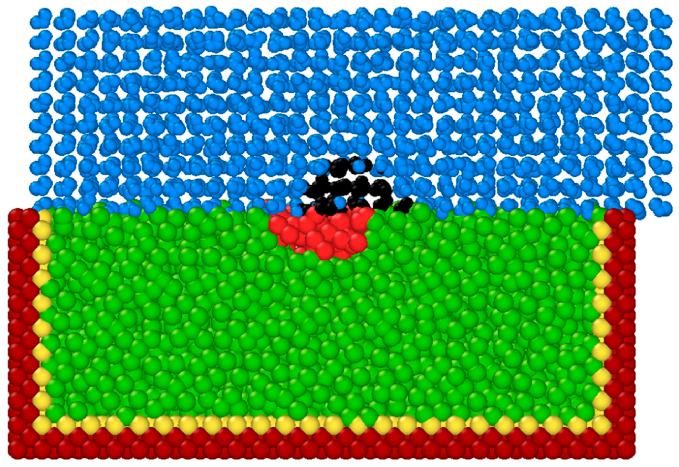
Figure 13.
Variation in the Number of Atoms Removed with respect to Heat Flux during the LA-LBMM Process for Static Mode and Dynamic Mode.
Figure 13.
Variation in the Number of Atoms Removed with respect to Heat Flux during the LA-LBMM Process for Static Mode and Dynamic Mode.
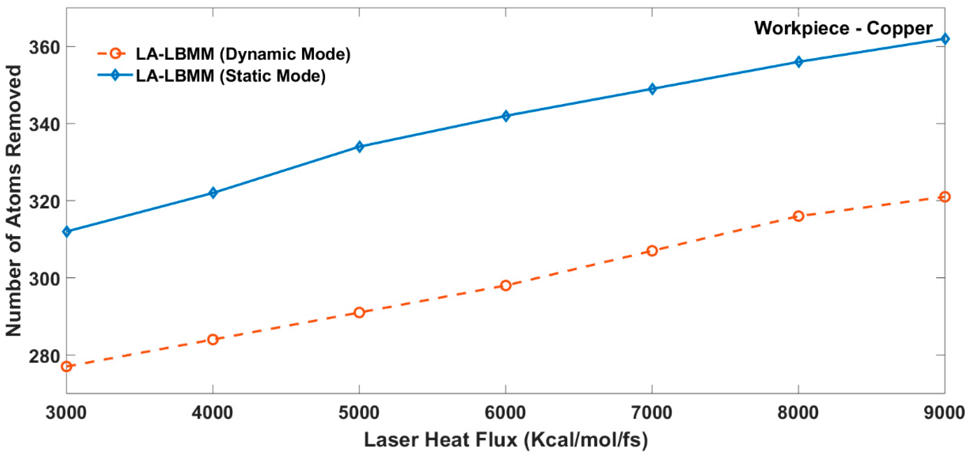
Figure 14.
MD Simulation Snapshot Showing Thermal Blanket Formation during LA-LBMM Process in Static Mode (a) Initial Stage (b) Final Stage.
Figure 14.
MD Simulation Snapshot Showing Thermal Blanket Formation during LA-LBMM Process in Static Mode (a) Initial Stage (b) Final Stage.
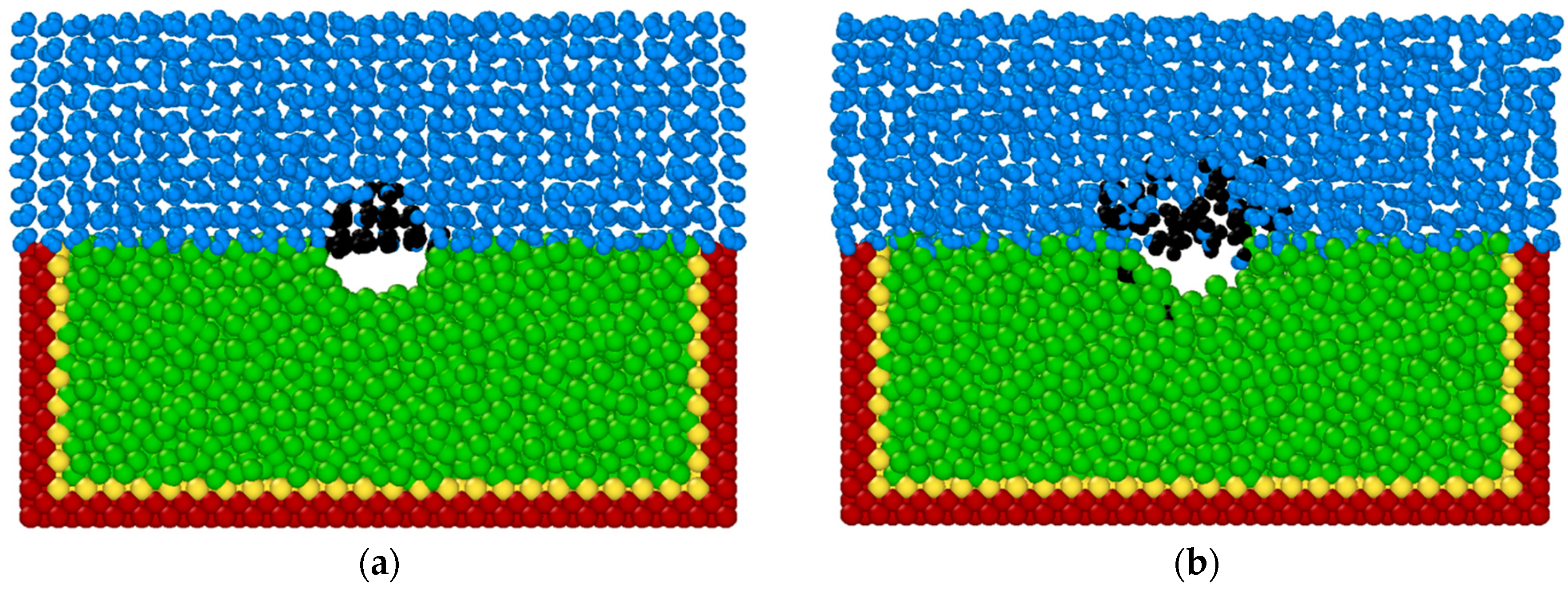
Figure 15.
MD Simulation Snapshot Showing Thermal Blanket Formation during LA-LBMM Process in Dynamic Mode (a) Initial Stage (b) Final Stage.
Figure 15.
MD Simulation Snapshot Showing Thermal Blanket Formation during LA-LBMM Process in Dynamic Mode (a) Initial Stage (b) Final Stage.
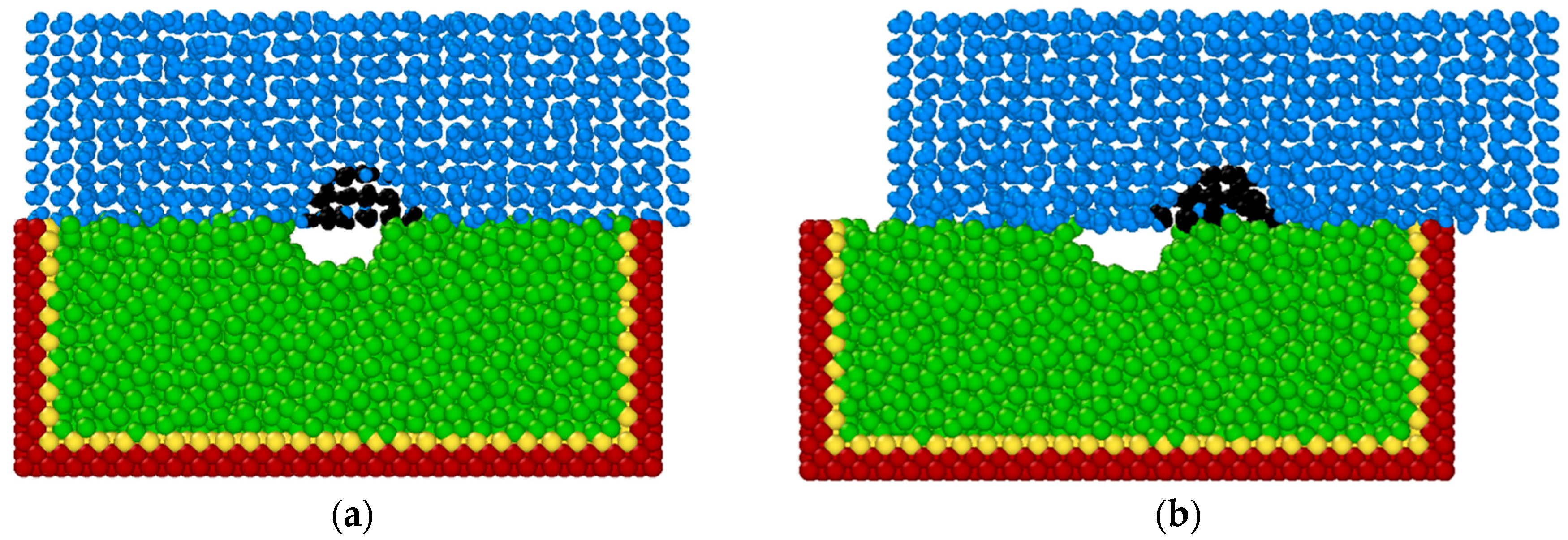
Figure 16.
MD Simulation Snapshot Showing the Formation of Cavities Leading to Bubble Formation during LA-LBMM Process in Static Mode.
Figure 16.
MD Simulation Snapshot Showing the Formation of Cavities Leading to Bubble Formation during LA-LBMM Process in Static Mode.
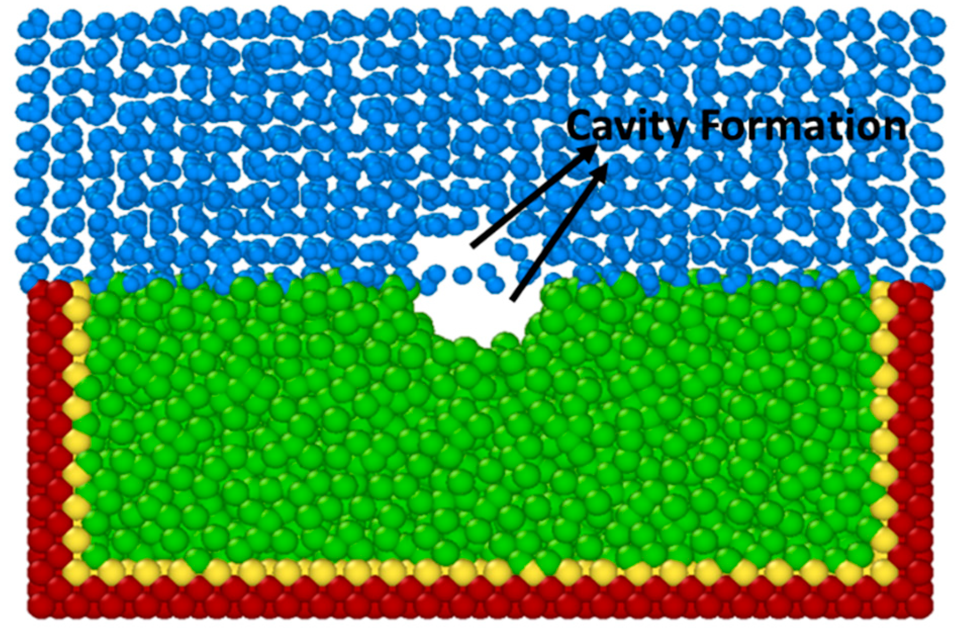
Figure 17.
Bubble Formation during LA-LBMM Process Experimentation (Right side image shows the magnified view of the circled region).
Figure 17.
Bubble Formation during LA-LBMM Process Experimentation (Right side image shows the magnified view of the circled region).
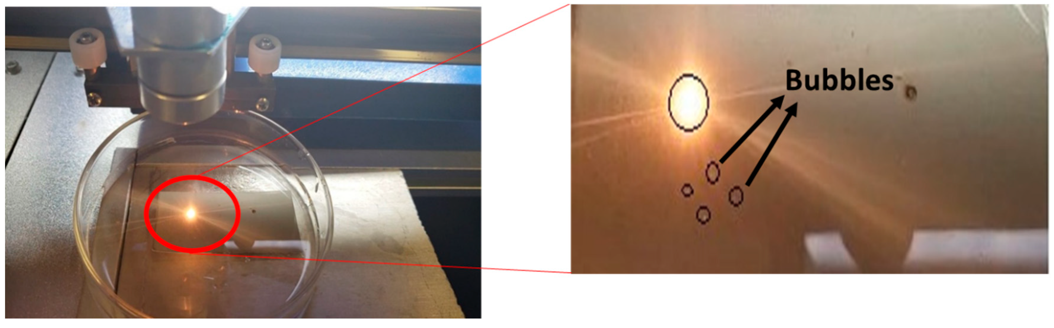
Figure 18.
MD Simulation Snapshot Showing Formation of Cavities Leading to Bubble Formation during LA-LBMM Process in Dynamic Mode.
Figure 18.
MD Simulation Snapshot Showing Formation of Cavities Leading to Bubble Formation during LA-LBMM Process in Dynamic Mode.

Figure 19.
Variation in Cavity Depth with Laser Intensity obtained through the LBMM and LA-LBMM (Static Mode) Experimentations.
Figure 19.
Variation in Cavity Depth with Laser Intensity obtained through the LBMM and LA-LBMM (Static Mode) Experimentations.

Table 1.
LJ potential parameters for O-O, Cu-O, Si-O, and C-O atom pairs.
| Parameter | O-O | Cu-O | Si-O | C-O |
|---|---|---|---|---|
| Equilibrium distance (σ, Å) | 3.166 | 2.644 | 3.629 | 2.744 |
| Cohesive energy (ε, 10−3, eV) | 6.736 | 43 | 231.9 | 62.0 |
| Cut-off distance (Å) | 9.8 | 5 | 10.0 | 7.0 |
Table 2.
Simulation Conditions Used in the MD Simulation of LBMM and LA-LBMM Process.
| Materials | Substrates |
|
| Water | H2O Block 30 Å Thick, 9000 Molecules | |
| Operating Conditions | Initial Temperature | 293 K |
| Laser Heat Flux | 3000 Kcal/mol/fs (Low)–9000 Kcal/mol/fs (High) | |
| Potential Used | EAM, Tersoff, Lennard-Jones (LJ) | |
| Duration of Simulation | 1 picosecond (ps) |
© 2018 by the authors. Licensee MDPI, Basel, Switzerland. This article is an open access article distributed under the terms and conditions of the Creative Commons Attribution (CC BY) license (http://creativecommons.org/licenses/by/4.0/).
Share and Cite
MDPI and ACS Style
Menon, V.A.; James, S. Molecular Dynamics Simulation Study of Liquid-Assisted Laser Beam Micromachining Process. J. Manuf. Mater. Process. 2018, 2, 51. https://doi.org/10.3390/jmmp2030051
AMA Style
Menon VA, James S. Molecular Dynamics Simulation Study of Liquid-Assisted Laser Beam Micromachining Process. Journal of Manufacturing and Materials Processing. 2018; 2(3):51. https://doi.org/10.3390/jmmp2030051
Chicago/Turabian StyleMenon, Vivek Anand, and Sagil James. 2018. "Molecular Dynamics Simulation Study of Liquid-Assisted Laser Beam Micromachining Process" Journal of Manufacturing and Materials Processing 2, no. 3: 51. https://doi.org/10.3390/jmmp2030051