Article

Finite-Time Adaptive Reinforcement Learning Control for a Class of Morphing Unmanned Aircraft with Mismatched Disturbances and Coupled Uncertainties

1
School of Astronautics, Harbin Institute of Technology, Harbin 150001, China
2
Jiangnan Electromechanical Design Institute, Guiyang 550009, China
3
Unmanned System Research Institute, Northwestern Polytechnical University, Xi’an 710072, China
*
Author to whom correspondence should be addressed.
Drones 2025, 9(8), 562; https://doi.org/10.3390/drones9080562
Submission received: 3 July 2025 / Revised: 31 July 2025 / Accepted: 6 August 2025 / Published: 11 August 2025
(This article belongs to the Section Drone Design and Development)

Abstract

Highlights

What are the main findings?
  • A novel RL-based adaptive finite-time control scheme for morphing unmanned aircraft is synthesized. It can address mismatched disturbances, coupled uncertainties, and non-affine characteristics, enabling the aircraft’s attitude to converge to the desired value within a finite time.
  • The attitude dynamics of the morphing unmanned aircraft are described as a class of mismatched non-affine systems, which are more suitable for practical scenarios and simplify the analysis process compared to previous models.
What is the implication of the main finding?
  • Applying reinforcement learning to morphing unmanned aircraft enhances its ability to handle uncertainties, and finite-time reinforcement learning helps limit the control convergence time, thus improving the trajectory-tracking control performance.
  • The proposed scheme for RL-based robust adaptive flight control offers a method that can be extended to various aircraft control research fields.

Abstract

This paper proposes a finite-time adaptive reinforcement learning (RL) control law for a class of morphing unmanned aircraft with mismatched disturbances and coupled uncertainties. To handle the mismatched disturbances, an adaptive upper-bound estimator as well as the parameter adaptive laws have been proposed. Aiming at the coupled uncertainties, an RL-based online uncertainty estimator and a corresponding finite-time compensation control law have been developed. To deal with the non-affine characteristics, an auxiliary integral system has been introduced. By systematically integrating the aforementioned adaptive upper-bound estimators, finite-time control law, and the auxiliary signals, a novel RL-based adaptive finite-time control framework is constructed for morphing unmanned aircraft. Simulation results reveal the finite-time convergence and the advantages of the proposed method.

1. Introduction

Morphing unmanned aircraft can optimize their aerodynamics and performance by changing their shape to adapt to diverse flight scenarios [1]. It can be classified by morphing scale, location, gas flow, and implementation method [2]. Yu et al. [3] and Noordin et al. [4] developed PID-based UAV adaptive control methods, achieving satisfactory tracking performance. As the application scenarios increase, there is an urgent need to improve its modeling and control law design [5]. Guidance and control technology is crucial as it ensures stable flight in complex environments, enables real-time adjustment of flight paths and morphing strategies, and enhances overall performance and adaptability [6,7]. He et al. [8] proposed an integrated guidance and control method using backstepping and fixed-time sliding mode control. This method includes a morphing term and solves the guidance and control problems of high-speed morphing aircraft. It stabilizes the system and makes errors converge quickly, thus improving control performance. Zhang et al. [9] presented an event-triggered fixed-time sliding mode control, which enhances the aircraft’s robustness and adaptability under complex conditions. Abouheaf et al. [10] developed a machine-learning-based autonomous morphing control for flexible-wing morphing aircraft. This method shows better stability than conventional model-free adaptive control approaches. The literature [11,12] designs a feedback-linearization-based nonlinear command and stability system for variable aspect ratio morphing aircraft. This system improves flexibility and fuel efficiency. The literature [13] proposes an online actor–critic control for variable aspect-ratio and swept-morphing-wing aircraft, which solves the problem of control input frequency. Numerical simulations prove its effectiveness. The literature [14] proposes a preset-performance sliding-mode controller for high-speed morphing unmanned aircraft attitude control under strong uncertainty. Paired with a finite-time neural network disturbance observer, it enhances the system’s performance and adaptability to disturbances and parameter changes. These methods combine advanced control theories to solve the high-speed guidance and control problems of morphing unmanned aircraft.
In recent years, advanced adaptive control approaches have been extensively researched and applied in the realm of complex and uncertain systems [15,16,17]. Among them, model reference adaptive control (MRAC) is a prominent technique that enables real-time parameter adjustment. It achieves this by comparing the performance of the system with a pre-established reference model. The literature [18,19,20] puts forward an enhanced nonlinear dynamic inversion control method based on MRAC. This innovation strengthens the aircraft’s resilience against faults and external disturbances. It refines the accuracy of adaptive estimation and incorporates a low-pass filter to optimize the balance between dynamic performance and robustness. To design the controller better, it is crucial to elucidate the distinctions and relationships among parameter uncertainties, disturbance rejection, and fault-tolerant control. Parameter uncertainties can be caused by sensor biases, which introduce inaccuracies in the measurement of system states. Actuator failures, on the other hand, represent a severe type of disturbance. These failures can disrupt the normal operation of the aircraft and require effective fault-tolerant control strategies to ensure safe flight. To ensure robust performance, researchers focus on parameter uncertainties and disturbance rejection. For robustness enhancement, fuzzy adaptive control effectively strengthens system robustness under uncertain and fuzzy operating conditions. As detailed in the literature [21], a novel fixed-time adaptive generalized type-2 fuzzy logic control scheme was devised for hypersonic aircraft grappling with uncertainties. The efficacy of this control scheme is validated through simulations. Based on the observer, a robust flight controller for a disturbance-unmanned aerial vehicle system is developed [22]. In addition, in the literature [23], the control problem of nonuniform nonlinear systems with time-varying delays in both state and input has also been discussed. Adaptive sliding mode control has also made significant strides in enhancing system robustness and responsiveness. In reference [24], a dedicated control strategy for hypersonic aircraft has been proposed. It constructs a dynamic uncertainty model and estimates uncertainty bounds online to coordinate the robustness and responsiveness of the controller. During flight, morphing unmanned aircraft experience complex shape alterations and fluctuations in aerodynamic characteristics. Traditional control methods like MRAC or sliding mode control often can’t accurately capture these nonlinear dynamics. To address this, some scholars have studied the finite-time asynchronous control of singular fuzzy Markov jump systems [25]. Their research resulted in an adaptive event-triggered scheme, which reduces communication frequency and improves system efficiency. Additionally, Shi et al. [26] introduced a distributed adaptive event-triggered control strategy to solve the cooperative output regulation problem in heterogeneous linear multi-agent systems.
Nevertheless, abrupt changes in morphing unmanned aircraft, particularly shape-switching events, can surpass the predefined triggering conditions. This may result in overly frequent or missed trigger events, thereby introducing instability into the system. Adaptive neural network control emerges as a viable solution. It can manage nonlinear and high-dimensional systems, ensuring stability under unknown dynamics and external disturbances. Research [27,28] introduced a fault-tolerant control approach that combines an adaptive neural network with a nonlinear observer. This synergy improves the robustness and real-time decision-making capabilities of nonlinear systems. To optimize control performance, reinforcement learning has been integrated into the adaptive control framework, expanding its applicability. Reference [29] presented an adaptive model-free fault-tolerant control solution based on integral reinforcement learning for highly flexible aircraft with actuator failures. Reinforcement-learning-based methods, with their distinct advantages in handling nonlinearity, model-free scenarios, real-time learning, and multi-objective optimization, can surmount the control challenges of morphing unmanned aircraft in complex environments.
However, most existing design methods for proving the Lyapunov stability theory can only achieve asymptotic stability. That is, the system takes an infinite time to converge to the equilibrium point [30,31,32,33]. In many engineering applications, it is desired that the control objectives be achieved as soon as possible. Thus, finite-time control has emerged. Finite-time control is applicable to different types of systems. For example, references [34,35,36] proposed finite-time control methods for different types of nonlinear systems, ensuring the finite-time stability of the closed-loop systems. In the aerospace field, finite-time control is mainly used for spacecraft attitude tracking. For instance, reference [37] studied the vibration suppression and attitude tracking of flexible spacecraft under model uncertainties and external disturbances. It designs a multivariable finite-time control scheme for spacecraft attitude tracking based on a novel dynamic sliding dynamics and an adaptive disturbance observer (ADO). Reference [38] investigated the finite-time tracking control problem of a class of nonlinear systems and proposed a new finite-time command-filtered backstepping method. This method has the advantages of conventional command-filtered backstepping control and ensures finite-time convergence.
Research [39] designed a concurrent-learning adaptive finite-time control based on inertial parameter identification under external disturbances and applied it to aerospace attitude control. Reference [40] proposed a novel discrete-time fuzzy preselected performance control (PPC) method. By employing an indirect stabilization mechanism and a low-computation fuzzy approximation strategy, this approach achieves finite-time convergent control of unknown system dynamics without the need for complex model reconstruction. Furthermore, reference [41] developed a fixed-time pre-configured controller for electromechanical systems based on enhanced fuzzy neural approximation and backstepping design. Extending this research to hypersonic vehicles with elevator-stuck faults, the authors propose a fuzzy fault-tolerant control scheme that ensures appointed-time convergence [42]. Reference [43] studied the spacecraft formation flying system affected by external disturbances and parameter uncertainties; it designed a new improved, fast integral terminal sliding-mode control law, and proposed an adaptive tracking control for the spacecraft formation flying system.
Only a few studies focus on applying finite-time control to morphing unmanned aircraft. In the early stage, Wang et al. [44] proposed a smooth-switching state-feedback controller design method for the altitude-keeping and attitude-stability problems of morphing unmanned aircraft during continuous morphing. They establish a chained smooth-switching system model and derive sufficient conditions for finite-time boundedness and robustness. Subsequently, Cheng et al. [45] studied the asynchronous finite-time H∞ control problem of morphing unmanned aircraft with controller uncertainties. Considering the inherent packet dropouts of the system and controller uncertainties, they propose a non-fragile finite-time H∞ controller design method, and its effectiveness is verified by numerical examples. In recent years, some scholars have combined finite-time control with disturbance observers to improve the robustness of morphing unmanned aircraft [46,47].
Based on the above analysis, the application of reinforcement learning to the trajectory-tracking control of morphing unmanned aircraft has not been reported yet. In particular, the research on finite-time reinforcement learning in this field is lacking. Considering the strong coupling and uncertainties of morphing unmanned aircraft, the application of reinforcement learning can enhance its ability to deal with uncertainties. Meanwhile, finite-time reinforcement learning can help limit and shorten the system’s stabilization and control convergence time. Therefore, it is of great significance to improve the trajectory-tracking control performance of morphing unmanned aircraft, and this paper will conduct in-depth research on this.
Based on the above analysis, the main contributions of this paper are as follows:
  • The attitude dynamics of the morphing unmanned aircraft are described as a class of mismatched non-affine systems, including matched and mismatched disturbances, non-affine input, and internal uncertainties. Compared to previous models [14,48,49], the proposed model is more applicable to practical scenarios and simplifies the analysis process.
  • Compared with the literature [13], our work focuses on finite-time control, mismatched disturbances, and coupled uncertainties, while the literature [13] addresses non-affine control systems and control input frequency constraints. Different from the literature [27] on highly flexible aircraft, our method targets morphing unmanned aircraft, devises adaptive finite-time controllers, and ensures finite-time attitude convergence with better performance.
  • This paper proposes a design framework for RL-based adaptive anti-disturbance flight control, offering a paradigm that can be extended to various aircraft.
The remainder of this paper is structured as follows. In Section 2, the problem is formulated, and preliminary knowledge is introduced. Section 3 presents the main findings. Section 4 provides simulation studies. Finally, Section 5 concludes the paper.

2. Problem Formulation and Preliminaries

2.1. Dynamic Model Description

The attitude dynamics model of a morphing unmanned aircraft can be formulated as follows [8,14]:
α ˙ β ˙ γ ˙ v = cos α tan β sin α tan β 1 sin α cos α 0 cos α sec β sin α sec β 0 ω x ω y ω z sec β cos γ v sin γ v tan β cos γ v θ ˙ sec β cos θ sin γ v cos θ cos γ v sin θ + tan β cos θ sin γ v σ ˙ ,
where α is the angle of attack, β is the sideslip angle, γ v is the tilt angle, θ is the velocity inclination angle, and σ is the track yaw angle, and ω x , ω y , ω z are the angular velocities of the roll, yaw, and pitch channels, respectively.
The longitudinal dynamics model of the aircraft is as follows:
ω ˙ = I b + j = L , r I b j 1 M c M f j = L , r m j r O m O j + r O j c j × v + ω × v ,
where ω = [ ω x , ω y , ω z ] T , I b denotes the moment of inertia of the aircraft body, I b j denotes the moment of inertia of the wing, M c represents the aerodynamic torque associated with control ability, M f is the additional moment caused by deformation, r O m O j is the rotation vector of the wing relative to the fuselage in this system, r O j c j is the rotation vector of the wing relative to the fuselage under the wing mounting system, v represents the matrix of velocity magnitudes, and m j is the mass of the aircraft wing, respectively. The detailed descriptions of some notations are as follows.
The I b j is expressed as:
I b j = m j r O m O j × × r O m O j × m j R b j r O j c j × × R b j T r O m O j × m j r O m O j × R b j r O j c j × × R b j T r O m O j × + R b j I j R b j T ,
where r O j c j × and r O m O j × represent the cross-product vector matrices of r O j c j and r O m O j , respectively, R b j is a rotation matrix from the wing installation frame to the body coordinate system, and is expressed as follows:
R b l = R y ( 90 ° + χ l ) T R b r = R y ( 90 ° χ r ) T ,
where R y is the basic rotation matrix of the y axis, and χ is the caster angle.
The M c can be given as follows:
M c = M c x M c y M c z = 1 2 ρ v 2 S 0 L 0 m c x m c y m c z ,
where ρ represents the atmospheric density, v is the velocity magnitude, S 0 represents the reference area, L 0 is the reference length, m c x , m c y , m c z represents the rotation moment coefficient, yaw moment coefficient, and pitch moment coefficient, respectively.
The determination of m c i can be presented by
m c i = m c i ( α , β , χ , δ x , δ y , δ z ) , i = x , y , z ,
where δ x , δ y and δ z represent the roll angle, yaw angle, and pitch angle, respectively.
The M f can be given as follows:
M f = ω b × I b ω b + j = L , r I b j ω ˙ j + j = L , r m j r O m O j × ω b × ω b × r O m O j + j = L , r m j r O j c j × ω b × ω b × r O m O j + j = L , r m j r O m O j × ω b + ω j × ω b + ω j × r O j c j ,
where I b j = R b j I b R b j T ,   ω b represents the angular velocity around the center of mass O m of the aircraft in the body coordinate system, ω j and ω ˙ j are the angular velocity and angular acceleration, respectively.
By defining the state variables x 1 = x 11 x 12 x 13 = α β γ v T and x 2 = x 21 x 22 x 23 T =   ω x ω y ω z T , control input u = δ x δ y δ z T , then (1) and (2) can be simplified in the following vector form with uncertain mismatched non-affine functions:
x ˙ 1 t = f 1 x 1 t + Δ f 1 x 1 t + g 1 x 1 t , x 2 t + d 1 t x ˙ 2 t = f 2 x 1 t , x 2 t + Δ f 2 x 1 t , x 2 t + g 2 x 1 t , x 2 t , u t + d 2 t ,
where Δ f 1 x 1 t and Δ f 2 x 1 t , x 2 t are the unknown structural uncertainties caused by the deformation of the aircraft, d 1 t and d 2 t represent the various unknown disturbances encountered during flight, g 1 x 1 t , x 2 t and g 2 x 1 t , x 2 t , u t denotes the non-affine functions, some notations are detailed as:
f 1 x 1 t = sec β cos γ v sin γ v tan β cos γ v T θ ˙ sec β cos θ sin γ v cos θ cos γ v sin θ + tan β cos θ sin γ v T σ ˙ ,
f 2 x 1 t , x 2 t = I b + j = L , r I b j 1 M f I b + j = L , r I b j 1 j = L , r m j r O m O j + r O j c j × v + ω × v .
g 1 x 1 t , x 2 t = cos α tan β sin α tan β 1 sin α cos α 0 cos α sec β sin α sec β 0 ω x ω y ω z , g 2 x 1 t , x 2 t , u t = I b + j = L , r I b j 1 m c x ( α , β , χ , δ x , δ y , δ z ) m c y ( α , β , χ , δ x , δ y , δ z ) m c z ( α , β , χ , δ x , δ y , δ z ) .
Remark 1. 
In the research of morphing unmanned aircraft control system modeling, to conform to real-world engineering practices and simplify the analysis, specific symbols are defined.  Δ f 1 x 1 t  and  Δ f 2 x 1 t , x 2 t  stand for unknown structural uncertainties due to aircraft deformation,  d 1 t  and  d 2 t  denote various unknown flight disturbances. These flight disturbances encompass sensor biases that can lead to parameter uncertainties, as well as actuator failures, which are a particularly severe type of disturbance. Additionally,  g 1 x 1 t , x 2 t  and  g 2 x 1 t , x 2 t , u t  represents non-affine functions. Furthermore, analysis of (9)–(11) shows that system (8) has significant non-affine features, posing great challenges to morphing unmanned aircraft control design.
Thereafter, when there is no risk of confusion, vectors may not be bolded, and function arguments may be omitted.
Based on the above analysis and simplification, the control-oriented morphing unmanned aircraft attitude model is obtained as an uncertain mismatched non-affine system as follows:
x ˙ 1 t = f 1 x 1 t + Δ f 1 x 1 t + g 1 x 1 t , x 2 t + d 1 t x ˙ 2 t = f 2 x 1 t , x 2 t + Δ f 2 x 1 t , x 2 t + g 2 x 1 t , x 2 t , u t + d 2 t y t = x 1 t ,
where y t represents the system output vector.
To design an RL-based adaptive fault-tolerant controller for a morphing unmanned aircraft facing external disturbances, unknown dynamics, and non-affine inputs, this paper sets two control goals: (a) All the signals in the closed-loop system are semi-global practical finite-time stable. (b) The racking errors converge to a small neighborhood of origin in a finite time.
The following assumptions and lemmas are necessary to design the controller.
Assumption 1. 
To ensure the validity of the input, it is assumed that  g 1 / x 1 ,   g 1 / x 2 , g 2 / x 1 , g 2 / x 2 , g 2 / u  are all invertible matrices, and it has [50,51]:
λ g i x 1 π _ ,   λ g i x 2 π _ ,   λ g 2 u π _ , i = 1 , 2 ,
where  λ g i / x 1 ,   λ g i / x 2  and  λ g 2 / u  represents the eigenvalue of the matrix  g i / x 1 , g i / x 2  and  g 2 / u , respectively.
Assumption 2. 
The desired trajectory  y d  and its first derivative are continuous and bounded [52].
Definition 1. 
If for all  ϵ ( t 0 ) = ϵ 0 , there exist  l > 0  and a settling time  T ( l , ϵ 0 ) <  such that  ϵ ( t ) < l  holds for all  t t 0 + T , then the equilibrium  ϵ = 0  of the nonlinear system  ϵ ˙ = f ( ϵ )  is semi-global practical finite-time stable [53].
Lemma 1. 
For any  ƛ > 0  and  x R , there exists [49,53]:
0 x x tanh x ƛ κ ƛ ,
where  κ = 0.2785 .
Lemma 2. 
Given any constants  > 0 ,  0 < l < 1 , and  > 0 , consider system  ϵ ˙ = f ( ϵ ) [54]. If there exists a smooth positive-definite function  V ( η )  such that:
V ˙ ( ϵ ) V l ( ϵ ) + , t 0 ,
holds, then system  ϵ ˙ = f ( ϵ )  is semi-global practical finite-time stable.
Lemma 3. 
For any real variables  p , q  and any positive constants  a 1 , a 2 , , the following inequality holds [55,56]:
p a 1 q a 2 a 1 a 1 + a 2 p a 1 + a 2 + a 2 a 1 + a 2 a 1 a 2 q a 1 + a 2 .
Lemma 4. 
For  Υ i R  and  0 < γ 1 , the following inequality holds [57]:
i = 1 n Υ i γ i = 1 n Υ i γ n 1 γ i = 1 n Υ i γ .

2.2. Designs of Actor–Critic Neural Networks

Research shows that radial basis function neural networks (RBFNNs) can approximate any smooth continuous function f x with any precision [58]. As a current research hotspot, the actor–critic framework enables the critic network to receive information from the environment and evaluate control performance through a cost function. Based on this evaluation, the actor network generates a control strategy for the actuator. Owing to the incorporation of reinforcement signals, the resulting control law exhibits faster convergence and reduced steady-state error. Based on this, an RL framework is developed in this study, using RBFNNs to approximate unknown nonlinear functions and penalty functions, namely:
f x = W a T Φ a x + ε a ( x ) , ε a x ε ¯ a ,
where x = x 1 , x 2 , x n T is the input vector of the RBFNN, ε x is the approximation error, W a is the optimized vector of the weight vector W a = υ _ 1 , υ _ 2 , , υ _ p T , and Φ a ( x ) = Φ 1 ( x ) , , Φ p ( x ) T is the basis function vector, p is the number of hidden nodes, Φ j ( x ) = e ( x μ j ) 2 / ( 2 σ j , 2 ) , j = 1 , , p is the basis function, μ j is the center of the basis function, σ j is the width of the Gaussian basis function, ε a ( x ) is the approximation error, and ε ¯ a is a positive integer.
When designing the actor–critic neural networks, several important design principles of the weight adaptive law in reinforcement learning are considered to ensure the effectiveness and stability of the system.
To approximate the unknown nonlinearity Δ f i x ¯ i in (12), an actor neural network W a i T Φ a i x ¯ i is introduced, which is expressed as follows:
Δ f i x ¯ i = W a i T Φ a i x ¯ i + ε a i ,
where x ¯ i = x 1 , x i T R i , i = 1 , 2 , W a i is the ideal actor neural network weight.
Define the weight error of the actor neural network as W ˜ a i = W ^ a i W a i , then its approximation error is expressed as:
H a i = W ˜ a i T Φ a i x ¯ i .
To improve the tracking performance, a new error function of the actor neural network is constructed based on the approximation error and the penalty function:
e a i = H a i + Γ i J ^ i , E a i = 1 2 e a i T e a i ,
where Γ i is the gain to be chosen, and the goal of updating the network weights to minimize E a i .
Based on the information gathered from the environment, an integral penalty function is constructed to generate RL signals:
J i ( t ) = τ q i ( t ) d t ,
where q i ( t ) = z i T Q i z i .
The specific meaning of the variables will be given later. The penalty function can be approximated by a critic neural network:
J i = W c i T Φ c i x ¯ i + ε c i , J ^ i = W ^ c i T Φ c i x ¯ i ,
where W c i is the ideal critic neural network weight.
The update rule for the weights of the actor–critic network is designed as follows:
W ^ ˙ a i = τ i η i W ^ a i η i Φ a i x ¯ i Φ a i T W ^ a i + J ^ i Γ i T ,
where η i > 0 , τ i > 0 are the parameters to be chosen.
Construct the residual mean square error function of the critic network:
e c i = q i ( t ) + J ^ ˙ i = q i ( t ) + W ^ c i T Φ ˙ c i x ¯ i , E c i = 1 2 e c i T e c i .
The update rule for the weights of the critic network is derived using the gradient descent method as follows:
W ^ ˙ c i = ϖ i W ^ c i T Φ ˙ c i + q i ( t ) Φ ˙ c i ω i ϖ i W ^ c i ,
where ω i and ϖ i are the positive design constants.
By applying these design principles, we can design an effective weight adaptive law for the actor–critic neural networks, which helps to improve the performance of the control system.
Remark 2. 
The  J ^  term approximates the unknown value function, enabling the actor to consider future rewards. This has helped the actor learn an optimal long-term policy, as focusing only on immediate rewards would lead to sub-optimal behavior. The second correction term enhances the stability and convergence of the actor–critic algorithm. It can adjust the actor’s update step, preventing aggressive updates that could cause divergence or oscillation. Moreover, it accounts for environmental uncertainties, improving the system’s robust ability to handle unexpected situations.
Property 1. 
To satisfy the persistence excitation condition, the basis functions  Φ c i  and  Φ a i , and the derivatives  Φ ˙ c i  and  Φ ˙ a i  are assumed to satisfy  Φ ˙ a i Φ a i m , Φ ˙ c i Φ c i m , Φ a i   Φ a i M , Φ c i Φ c i M , i = 1 , 2 . Meanwhile, the estimation errors of actor–critic learning and their derivative are bounded, that is  ε c i ε c i M  and  ε ˙ c i ε c i m [51].
Remark 3. 
RBFNNs are selected over other function approximations for several well-founded reasons. Firstly, owing to their universal approximation property, RBFNNs are capable of accurately approximating uncertainties [52]. Secondly, for high-dimensional data, RBFNNs offer computational efficiency as their training process is relatively straightforward.
Remark 4. 
When determining the centers and widths, a trial-and-error technique is used to process the input data. The centers are set in high-density regions, and prior knowledge of the system’s critical operating points is incorporated. The widths are set according to the distances between the centers and fine-tuned on the validation set.
Remark 5. 
The penalty function (22) and update laws (24) and (26) are designed with the aim of ensuring the stability and convergence of the RL framework. The penalty function serves to penalize undesired system behaviors, and the update laws are derived from Lyapunov techniques. The detailed derivations of these aspects will be presented in the revised manuscript.
Remark 6. 
The actor–critic neural network and RBFNN architectures, learning mechanisms, and generalization abilities are designed to suit different application scenarios. The actor–critic is for dynamic scenarios, while RBFNN excels at local function approximation.

3. Main Results

This section details the design process of the RL-based adaptive fault-tolerant control method. First, by introducing an auxiliary integral term, the system is reformulated as an augmented affine system with the overall non-affine function treated as the control input. Next, a virtual control law is designed, which integrates the actor–critic network and the disturbance boundary estimator. The final control signal is obtained through recursive design, and the actual control input is generated through integration. The structure of the controller is shown in Figure 1.

3.1. The Design of the Augmented System

Through the auxiliary integration method, the augmented system is established as follows:
x ˙ 1 t = f 1 x 1 t + Δ f 1 x 1 t + g 1 x 1 t , x 2 t + d 1 t x ˙ 2 t = f 2 x 1 t , x 2 t + Δ f 2 x 1 t , x 2 t + g 2 x 1 t , x 2 t , u t + d 2 t u ˙ = u f y t = x 1 t ,
where d 1 t denotes mismatched disturbance, d 2 t denotes matched disturbance, which are compensated by the Tanh function boundary estimator. Additionally, unknown nonlinear functions Δ f 1 x 1 t , Δ f 2 x 1 t , x 2 t are approximated using an actor–critic framework.
Different from the affine system, non-affine systems treat the non-affine function holistically as the subsystem input, with the tracking error formally defined as follows:
z 1 t = x 1 t y d z 2 t = g 1 x 1 t , x 2 t x 1 d t z 3 t = g 2 x 1 t , x 2 t , u t x 2 d t ,
where y d is the desired output value of the system, x 1 d and x 2 d , the constructed virtual control variables, will be presented below.
Let x i c denote the virtual control law to be designed for the i-th subsystem. To mitigate differential explosion, a first-order low-pass filter [58] is introduced as:
δ i x ˙ i d + x i d = x i c , x i d 0 = x i c 0 , i = 1 , 2 ,
where 0 < δ i < 1 denotes the filter time constant to be designed, through which both x i d and its derivative can be obtained. The boundary layer error is defined as:
y i = x i d x i c ,
where x i c denotes the filtered value of the virtual controller x i d .
Then we can obtain:
y ˙ i = x ˙ i d x ˙ i c = y i δ i x ˙ i c .

3.2. Controller Design

Step 1. From the first equality in Equation (28), it yields:
z ˙ 1 t = x ˙ 1 t y ˙ d = f 1 x 1 t + Δ f 1 x 1 t + g 1 x 1 t , x 2 t + d 1 t y ˙ d = f 1 + z 2 + y 1 + x 1 c + d 1 + Δ f 1 y ˙ d .
Let Δ f ^ 1 denote the estimated value of the inner-loop nonlinearity Δ f 1 . According to Section 2.2, it can be approximated using an actor network, expressed as:
Δ f 1 = W a 1 T Φ a 1 ( x 1 ) + ε a 1 ,
where ε a 1 is the error of the actor network.
Define D 1 = sup t 0 d 1 t + ε a 1 , thus, the virtual controller can be designed as:
x 1 c = k 1 z 1 T z 1 l 1 z 1 W ^ a 1 T Φ 1 x 1 D ^ 1 tanh z 1 ε D 1 f 1 + y ˙ d .
Let D ^ 1 denote the estimated value of the mismatched disturbance. From Equations (32) and (34), we obtain:
z 1 T z ˙ 1 = k 1 z 1 T z 1 l + z 1 T z 2 + y 1 + z 1 T d 1 + ε a 1 D ^ 1 tanh z 1 ε D 1 z 1 T W ˜ a 1 T Φ a 1 x 1 ,
where W ˜ a 1 = W ^ a 1 W a 1 .
The integral penalty function of the control system is defined as: J 1 ( t ) = τ q 1 ( t ) d t , where q 1 ( t ) = z 1 , T Q 1 z 1 . Then, the actor–critic network weight updating law is designed as:
W ^ ˙ a 1   = τ 1 η 1 W ^ a 1 η 1 Φ a 1 ( x 1 ) [ Φ a 1 , T W ^ a 1 + J ^ 1 Γ 1 T ]   .
The critic network weight updating law is derived via the gradient descent method as:
W ^ ˙ c 1 = ϖ 1 ( W ^ ˙ c 1 T Φ ˙ c 1 + q 1 ( t ) ) Φ ˙ c 1 ω 1 ϖ 1 W ^ c 1 .
The updating law of D ^ 1 is given as:
D ^ ˙ 1 = τ D 1 z 1 tanh z 1 ε D 1 τ D 1 γ D 1 D ^ 1 .
Step 2. Define D 2 = sup t 0 d 2 t + ε a 2 , where D ^ 2 is the estimated value. According to Equation (28), we have:
z ˙ 2 = g ˙ 1 x ˙ 1 d = g 1 x 1 x ˙ 1 + g 1 x 2 x ˙ 2 x ˙ 1 d = g 1 x 1 f 1 + g 1 + d 1 + Δ f 1 + g 1 x 2 f 2 + Δ f 2 + z 3 + y 2 + x 2 c + d 2 x ˙ 1 d .
Introduce the actor network to compensate Δ f 2 t , x 1 , x 2 :
Δ f 2 t , x 1 , x 2 = W a 2 T Φ a 2 x 1 , x 2 + ε a 2 , Δ f ^ 2 t , x 1 , x 2 = W ^ a 2 T Φ a 2 x 1 , x 2 .
The designed virtual control law is:
x 2 c = g 1 x 2 1 k 2 z 2 T z 2 l 1 z 2 ( 1 2 + 5 2 π _ 2 ) z 2 g 1 x 1 f 1 + g 1 + D ^ 1 tanh z 1 ε D 1 + W ^ a 1 T Φ a 1 x 1 g 1 x 2 W ^ a 2 T Φ a 2 x 1 , x 2 + f 2 + D ^ 2 tanh g 1 x 2 z 2 ε D 2 + x ˙ 1 d .
Substituting into Equation (39), it yields:
z 2 T z ˙ 2 = k 2 z 2 T z 2 l + g 1 x 1 z 2 d 1 + ε a 1 D ^ 1 tanh z 1 ε D 1 g 1 x 1 z 2 W ˜ a 1 T Φ a 1 x 1   + g 1 x 2 z 2 z 3 + y 2     g 1 x 2 z 2 W ˜ a 2 T Φ a 2 x 1 , x 2 + g 1 x 2 z 2 d 2 + ε a 2 D ^ 2 tanh g 1 x 2 z 2 ε D 2
Similarly, the actor–critic framework is designed with the penalty function defined as: J 2 ( t ) = τ q 2 ( t ) d t and q 2 ( t ) = z 2 , T Q 2 z 2 .
Construct the critic network module effect error function and design the weight update law as:
W ^ ˙ a 2   = g 1 x 2 η 2 Φ a 2 ( x 2 ) [ g 1 x 2 Φ a 2 , T W ^ a 2 + J ^ 2 Γ 2 T ] η 2 τ 2 W ^ a 2 , W ^ ˙ c 2 = ϖ 2 ( W ^ ˙ , c 2 T Φ ˙ c 2 + q 2 ( t ) ) Φ ˙ c 2 ω 2 ϖ 2 W ^ c 2 .
The updating law of D ^ 2 is given as:
D ^ ˙ 2 = g 1 x 2 τ D 2 z 2 tanh g 1 x 2 · z 2 ε D 2 τ D 2 γ D 2 D ^ 2 .
Step 3. From the third equation of Equation (28), let u f t = u ˙ t , it can be obtained:
z ˙ 3 = g ˙ 2 x ˙ 2 d = g 2 x 1 x ˙ 1 + g 2 x 2 x ˙ 2 + g 2 u u ˙ x ˙ 2 d = g 2 x 1 f 1 + g 1 + d 1 + Δ f 1 + g 2 x 2 f 2 + g 2 + Δ f 2 + d 2 + g 2 u u f x ˙ 2 d .
The virtual control signal is designed as:
u f = g 2 u 1 k 3 z 3 T z 3 l 1 z 3 ( 1 2 + 2 π _ 2 ) z 3 g 2 x 1 f 1 + g 1 + D ^ 1 tanh z 1 ε D 1 + W ^ a 1 T Φ a 1 x 1 g 2 x 2 f 2 + g 2 + D ^ 2 tanh g 1 x 2 z 2 ε D 2 + W ^ a 2 T Φ a 2 x 1 , x 2 + x ˙ 2 d .
We can obtain:
z 3 T z ˙ 3 = k 3 z 3 T z 3 l + g 2 x 1 z 3 d 1 + ε a 1 D ^ 1 tanh z 1 ε D 1 g 2 x 1 z 3 W ˜ a 1 T Φ a 1 x 1 + g 2 x 2 z 3 d 2 + ε a 2 D ^ 2 tanh g 1 x 2 · z 2 ε D 2 g 2 x 2 z 3 W ˜ a 2 T Φ a 2 x 1 , x 2 .

3.3. Proof of Stability

Theorem 1. 
For a second-order non-affine nonlinear system that satisfies Assumptions 1–2 and Lemmas 1–4, if the virtual control signals, adaptive laws, and reinforcement learning (RL) update laws are designed as described in Section 3.1, the closed-loop system can achieve the control the objectives (a) and (b).
Proof. 
① Choose the overall candidate Lyapunov function as:
V = 1 2 z 1 T z 1 + 1 2 z 2 T z 2 + 1 2 z 3 T z 3 + 1 2 y 1 T y 1 + 1 2 y 2 T y 2 + 1 2 T r ( W ˜ a 1 T η 1 1 W ˜ a 1 ) + 1 2 T r ( W ˜ c 1 T ϖ 1 1 W ˜ c 1 ) + 1 2 T r ( W ˜ a 2 T η 2 1 W ˜ a 2 ) + 1 2 T r ( W ˜ c 2 T ϖ 2 1 W ˜ c 2 ) + 1 2 τ D 1 D ˜ 1 T D ˜ 1 + 1 2 τ D 2 D ˜ 2 T D ˜ 2
By taking its derivative, we can obtain:
V ˙ = z 1 T z ˙ 1 + z 2 T z ˙ 2 + z 3 T z ˙ 3 + y 1 T y ˙ 1 + y 2 T y ˙ 2 + 1 τ D 1 D ˜ 1 T D ^ ˙ 1 + 1 τ D 2 D ˜ 2 T D ^ ˙ 2 + T r ( W ˜ a 1 T η 1 1 W ^ ˙ a 1 ) + T r ( W ˜ c 1 T ϖ 1 1 W ^ ˙ c 1 ) + T r ( W ˜ a 2 T η 2 1 W ^ ˙ a 1 ) + T r ( W ˜ c 2 T ϖ 2 1 W ^ ˙ c 2 ) = k 1 z 1 T z 1 l k 2 z 2 T z 2 l k 3 z 3 T z 3 l 3 2 z 1 T z 1 ( 1 2 + 5 2 π _ 2 ) z 2 T z 2 ( 1 2 + 2 π _ 2 ) z 3 T z 3 y 1 T y 1 δ 1 x ˙ 1 c T y 1 y 2 T y 2 δ 2 x ˙ 2 c T y 2 + z 1 z 2 + y 1 + g 1 x 2 z 2 z 3 + y 2 + d 1 + ε a 1 D ^ 1 tanh z 1 ε D 1 z 1 + ( g 1 x 1 z 2 + g 2 x 1 z 3 ) d 1 + ε a 1 D ^ 1 tanh z 1 ε D 1 + d 2 + ε a 2 D ^ 2 tanh g 1 x 2 · z 2 ε D 2 g 1 x 2 z 2 + g 2 x 2 z 3 d 2 + ε a 2 D ^ 2 tanh g 1 x 2 · z 2 ε D 2 W ˜ a 1 T Φ a 1 x 1 ( z 1 + g 1 x 1 z 2 + g 2 x 1 z 3 ) W ˜ a 2 T Φ a 2 x 1 , x 2 ( g 1 x 2 z 2 + g 2 x 2 z 3 ) + 1 τ D 1 D ˜ 1 T D ^ ˙ 1 + 1 τ D 2 D ˜ 2 T D ^ ˙ 2 + T r ( W ˜ a 1 T η 1 1 W ^ ˙ a 1 ) + T r ( W ˜ c 1 T ϖ 1 1 W ^ ˙ c 1 ) + T r ( W ˜ a 2 T η 2 1 W ^ ˙ a 2 ) + T r ( W ˜ c 2 T ϖ 2 1 W ^ ˙ c 2 ) .
According to Lemma 3, we have:
x ˙ 1 c T y 1 y 1 T y 1 2 δ 1 + δ 1 x ˙ 1 c 2 2 ,   x ˙ 2 c T y 2 y 2 T y 2 2 δ 2 + δ 2 x ˙ 2 c 2 2 , z 1 T z 2 + y 1 + g 1 x 2 z 2 z 3 + y 2 z 1 T z 1 + 1 2 + π _ 2 z 2 T z 2 + 1 2 z 3 T z 3 + 1 2 y 1 T y 1 + 1 2 y 2 T y 2 , ( g 1 x 1 z 2 + g 2 x 1 z 3 ) d 1 + ε a 1 D ^ 1 tanh z 1 ε D 1 1 2 π _ 2 z 2 T z 2 + 1 2 π _ 2 z 3 T z 3 + 3 2 ε ¯ D 1 2 , g 2 x 2 z 3 d 2 + ε a 2 D ^ 2 tanh g 1 x 2 z 2 ε D 2 1 2 π _ 2 z 3 T z 3 + 1 2 ε ¯ D 2 2 , W ˜ a 1 T Φ a 1 x 1 ( z 1 + g 1 x 1 z 2 + g 2 x 1 z 3 ) 1 2 z 1 T z 1 + 1 2 π _ 2 ( z 2 T z 2 + z 3 T z 3 ) + 3 2 Φ a 1 M 2 T r W ˜ a 1 , T W ˜ a 1 , W ˜ a 2 T Φ a 2 x 1 , x 2 ( g 1 x 2 z 2 + g 2 x 2 z 3 ) 1 2 π _ 2 ( z 2 T z 2 + z 3 T z 3 ) + Φ a 2 M 2 T r W ˜ a 2 , T W ˜ a 2 .
It follows from Lemma 1 that:
z 1 d 1 + ε a 1 D ^ 1 tanh z 1 ε D 1 D ˜ 1 z 1 tanh z 1 ε D 1 + κ ε D 1 , g 1 x 2 z 2 d 2 + ε a 2 D ^ 2 tanh g 1 x 2 z 2 ε D 2 D ˜ 2 g 1 x 2 z 2 tanh g 1 x 2 z 2 ε D 2 + κ ε D 2 .
Combing Equations (38) and (44), we can obtain:
1 τ D 1 D ˜ 1 T D ^ ˙ 1 = D ˜ 1 z 1 tanh z 1 ε D 1 γ D 1 D ^ 1 D ˜ 1 , 1 τ D 2 D ˜ 2 T D ^ ˙ 2 = D ˜ 2 g 1 x 2 z 2 tanh g 1 x 2 · z 2 ε D 2 γ D 2 D ^ 2 D ˜ 2 .
Through transforming the inequalities, we derive the following relationship:
γ D 1 D ^ 1 T D ˜ 1 1 2 γ D 1 D ˜ 1 T D ˜ 1 + 1 2 γ D 1 D 1 T D 1 , γ D 2 D ^ 2 T D ˜ 2 1 2 γ D 2 D ˜ 2 T D ˜ 2 + 1 2 γ D 2 D 2 T D 2 , T r ( W ˜ a 1 T η 1 1 W ˜ ˙ a 1 , ) + T r ( W ˜ c 1 T ϖ 1 1 W ˜ ˙ c 1 , ) 1 2 τ 1 Φ a 1 M 2 T r W ˜ a 1 , T W ˜ a 1 1 2 ω 1 Φ c 1 m 2 Φ c 1 M 2 Γ 1 M 2 T r W ˜ c 1 , T W ˜ c 1 + 1 2 τ 1 + Φ a 1 M 2 T r ( W a 1 , T W a 1 ) + 1 2 ω 1 + 2 Φ c 1 m 2 + Φ c 1 M 2 Γ 1 M 2 T r W c 1 T W c 1 + 1 2 ε c 1 m 2 , T r ( W ˜ , a 2 T η 2 1 W ˜ ˙ , a 2 , ) + T r ( W ˜ , c 2 T ϖ 2 1 W ˜ ˙ , c 2 , ) 1 2 ( τ 2 π _ 2 Φ a 2 M 2 2 π Φ a 2 M 2 ) T r ( W ˜ a 2 , T W ˜ a 2 ) 1 2 ( ω 2 Φ c 2 m 2 π _ Φ c 2 M 2 Γ 2 M 2 ) T r ( W ˜ , c 2 T W ˜ c 2 ) + 1 2 ( π _ 2 Φ a 2 M 2 + τ 2 ) T r W a 2 , T W a 2 + 1 2 ( π _ Φ c 2 M 2 Γ 2 M 2 + ω 2 + 2 Φ c 2 m 2 ) T r ( W , c 2 T W c 2 ) + 1 2 ε c 2 m 2 .
It can be sorted out:
V ˙ k 1 z 1 T z 1 l k 2 z 2 T z 2 l k 3 z 3 T z 3 l ( 1 2 δ 1 1 2 ) y 1 T y 1 ( 1 2 δ 2 1 2 ) y 2 T y 2 1 2 γ D 1 D ˜ 1 T D ˜ 1 1 2 γ D 2 D ˜ 2 T D ˜ 2 1 2 τ 1 4 Φ a 1 M 2 T r W ˜ a 1 , T W ˜ a 1 1 2 ω 1 Φ c 1 m 2 Φ c 1 M 2 Γ 1 M 2 T r W ˜ c 1 , T W ˜ c 1 1 2 ( τ 2 π _ 2 Φ a 2 M 2 2 π _ Φ a 2 M 2 2 Φ a 2 M 2 ) T r ( W ˜ a 2 , T W ˜ a 2 ) 1 2 ( ω 2 Φ c 2 m 2 π _ Φ c 2 M 2 Γ 2 M 2 ) T r ( W ˜ c 2 T W ˜ c 2 ) + κ ε D 1 + 3 2 ε ¯ D 1 2 + κ ε D 2 + 1 2 ε ¯ D 2 2 + 1 2 γ D 1 D 1 T D 1 + 1 2 γ D 2 D 2 T D 2 + δ 1 x ˙ 1 c 2 2 + δ 2 x ˙ 2 c 2 2 + 1 2 τ 1 + Φ a 1 M 2 T r ( W a 1 , T W a 1 ) + 1 2 ω 1 + 2 Φ c 1 m 2 + Φ c 1 M 2 Γ 1 M 2 T r W c 1 T W c 1 + 1 2 ε c 1 m 2 + 1 2 ( π _ 2 Φ a 2 M 2 + τ 2 ) T r W a 2 , T W a 2 + 1 2 ( π _ Φ c 2 M 2 Γ 2 M 2 + ω 2 + 2 Φ c 2 m 2 ) T r ( W , c 2 T W c 2 ) + 1 2 ε c 2 m 2 .
By defining:
C ¯ = min 2 k 1 , 2 k 2 , 2 k 3 , ( 1 δ 1 1 ) , ( 1 δ 2 1 ) , τ D 1 γ D 1 , τ D 2 γ D 2 , τ 1 4 Φ a 1 M 2 , ω 1 Φ c 1 m 2 Φ c 1 M 2 Γ 1 M 2 , ( τ 2 π _ 2 Φ a 2 M 2 2 π _ Φ a 2 M 2 2 Φ a 2 M 2 ) , ( ω 2 Φ c 2 m 2 π _ Φ c 2 M 2 Γ 2 M 2 ) ,
ε = κ ε D 1 + 3 2 ε ¯ D 1 2 + κ ε D 2 + 1 2 ε ¯ D 2 2 + 1 2 γ D 1 D 1 T D 1 + 1 2 γ D 2 D 2 T D 2 + δ 1 x ˙ 1 c 2 2 + δ 2 x ˙ 2 c 2 2 + 1 2 τ 1 + Φ a 1 M 2 T r ( W a 1 , T W a 1 ) + 1 2 ω 1 + 2 Φ c 1 m 2 + Φ c 1 M 2 Γ 1 M 2 T r W c 1 T W c 1 + 1 2 ε c 1 m 2 + 1 2 ( π _ 2 Φ a 2 M 2 + τ 2 ) T r W a 2 , T W a 2 + 1 2 ( π _ Φ c 2 M 2 Γ 2 M 2 + ω 2 + 2 Φ c 2 m 2 ) T r ( W c 2 T W c 2 ) + 1 2 ε c 2 m 2 .
Then, Equation (54) can be rewritten as:
V ˙ 1 2 C ¯ z 1 T z 1 l 1 2 C ¯ z 2 T z 2 l 1 2 C ¯ z 3 T z 3 l 1 2 C ¯ y 1 T y 1 1 2 C ¯ y 2 T y 2 C ¯ 2 τ D 1 D ˜ 1 T D ˜ 1 C ¯ 2 τ D 2 D ˜ 2 T D ˜ 2 C ¯ 2 η 1 T r W ˜ a 1 , T W ˜ a 1 C ¯ 2 ϖ 1 T r W ˜ c 1 , T W ˜ c 1 C ¯ 2 η 1 T r ( W ˜ a 2 , T W ˜ a 2 ) C ¯ 2 ϖ 2 T r ( W ˜ c 2 T W ˜ c 2 ) + ε .
According to Lemma, we obtain:
1 2 y i T y i l 1 l l l 1 l + 1 2 y i T y i , 1 2 τ D i D ˜ i T D ˜ i l 1 l l l 1 l + 1 2 τ D i D ˜ i T D ˜ i , 1 2 η i T r W ˜ a i , T W ˜ a i l 1 l l l 1 l + 1 2 η i T r W ˜ a i , T W ˜ a i , 1 2 ϖ i T r W ˜ c i , T W ˜ c i l 1 l l l 1 l + 1 2 ϖ i T r W ˜ c i , T W ˜ c i .
It follows from Lemma 4 that:
C ¯ 1 2 z i T z i l 2 l 1 C ¯ 1 2 z i T z i l .
Finally, we can obtain:
V ˙ 2 l 1 C ¯ 1 2 z 1 T z 1 l 2 l 1 C ¯ 1 2 z 2 T z 2 l 2 l 1 C ¯ 1 2 z 3 T z 3 l C ¯ 1 2 y 1 T y 1 l + 9 C ¯ 1 l l l 1 l C ¯ 1 2 y 2 T y 2 l C ¯ 1 2 y 3 T y 3 l C ¯ 1 2 τ D 1 D ˜ 1 T D ˜ 1 l C ¯ 1 2 τ D 2 D ˜ 2 T D ˜ 2 l C ¯ 1 2 η 1 T r W ˜ a 1 , T W ˜ a 1 l C ¯ 1 2 η 2 T r W ˜ a 2 , T W ˜ a 2 1 2 ϖ 2 T r W ˜ c 2 , T W ˜ c 2 l + ε .
Let:
C = min 2 l 1 C ¯ , C ¯ D = ε + 9 C ¯ 1 l l l 1 l .
Then, Equation (60) can be rewritten as:
V ˙ C V l + D .
Based on Lemma 2, selecting the parameters k i > 0 , i = 1 , 2 , 3 , 0 < δ i < 1 , τ D i > 0 , γ D i > 0 , τ 1   > 4 Φ a 1 M 2 , ω 1 > Φ c 1 m 2 + Φ c 1 M 2 Γ 1 M 2 , τ 2 > π _ 2 Φ a 2 M 2 + 2 π _ Φ a 2 M 2 + 2 Φ a 2 M 2 , ω 2 > Φ c 2 m 2 + π _ Φ c 2 M 2 Γ 2 M 2 + π _ Φ c 2 M 2 Γ 2 M 2 ,   i = 1 , 2 to derive the explicit conditions for C ¯ > 0 , we conclude that all the signals of the closed-loop system are semi-global practical finite-time stable.
② Given T r = 1 ( 1 l ) C V 1 l ( 0 ) D ( 1 ) C Ξ , where Ξ = ( 1 l ) / l , ( 0 , 1 ) . With the analysis in [52], it yields:
V D 1 C 1 / l , t T r .
Then, combining Equation (48), it can be obtained:
z 1 t = x 1 t y d < 2 D ( 1 ) C 1 2 l , t T r .
Thereby, it can be concluded that the tracking error converges to and remains in a small neighborhood of the desired signals for t T r . □
Remark 7. 
The system tracking error  z 1 t enters and remains within a steady-state neighborhood determined by the parameters  D , C , , l , after a finite time  T r . The convergence process can be accelerated by appropriately increasing the value of  l .

4. Simulation Study

In this section, numerical simulations are performed to confirm the effectiveness and advantages of the developed RL-based finite-time adaptive fault tolerant control method for a morphing unmanned aircraft.
The initial conditions are chosen as: α β γ v T = 20 5 5 T , [ ω x ω y ω z ] T =   0.1 r a d / s 0.1 r a d / s 0.1 r a d / s T ; The adaptive parameters and RL parameters are set as: k 1 = 3 , k 2 = 5 , k 3 = 8 , τ 1 = τ 2 = 8 , η 1 = 10 , η 2 = 1 , ϖ 1 = 5 , ϖ 2 = 0.5 , ω 1 = 0.5 , ω 2 = 0.1 ; The disturbance compensation adaptative parameters are defined as: ε D 1 = ε D 2 = 0.01 , τ D 1 = τ D 2 = 10 , γ D 1 = γ D 2 = 10 ; Structural parameters of the morphing unmanned aircraft: I b x = 20 , I b y = I b , z = 150 ; The aircraft’s flight velocity is V = 600 m/s, and its flight altitude is H = 15 km. To ensure the proper implementation of the simulations, they are conducted under three different cases. The different parameters of the uncertainties Δ f 1 , Δ f 2 and disturbances d 1 t and d 2 t expressed in model (27) are defined under three cases. The detailed specifications of these scenarios are presented in Table 1.
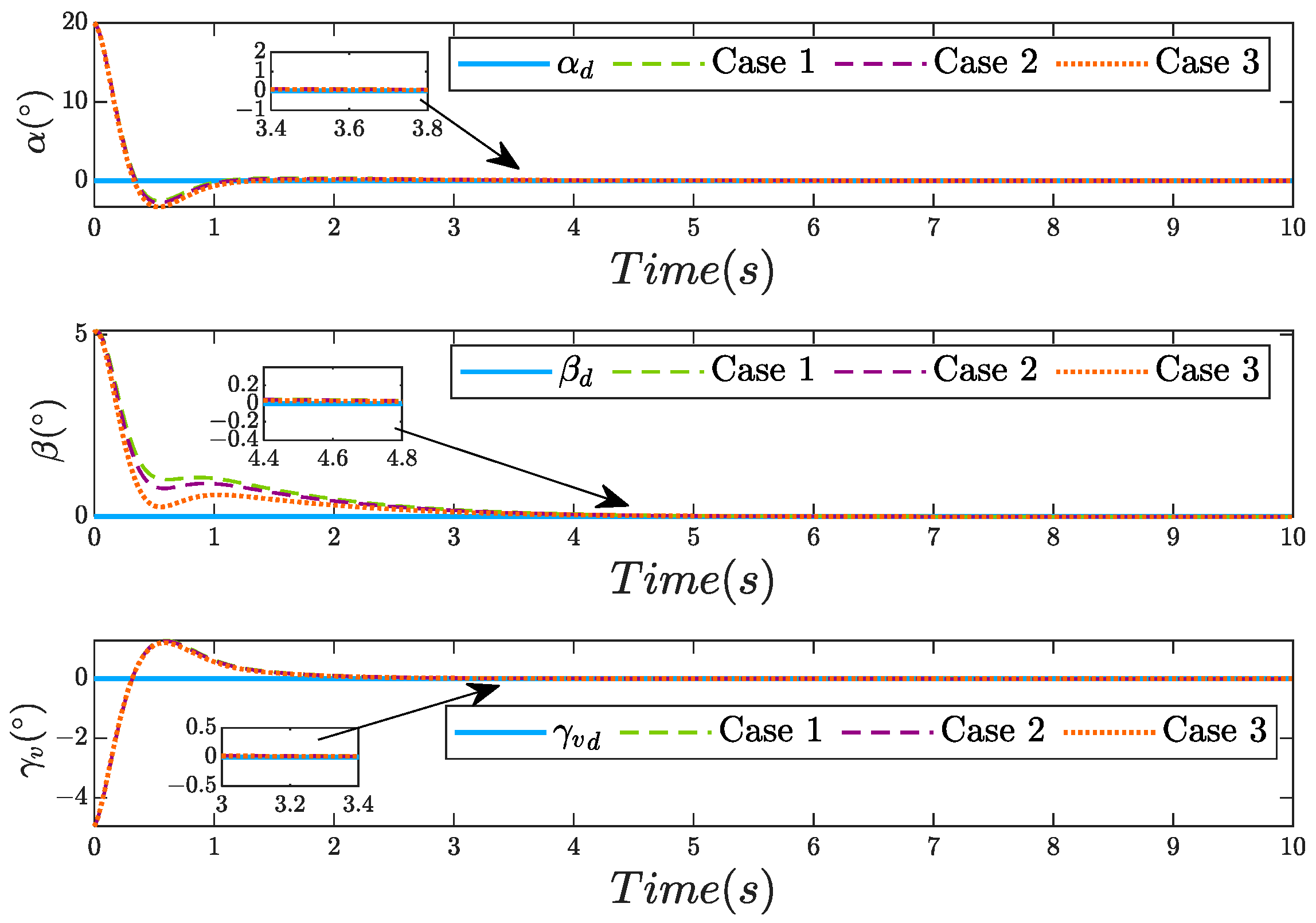
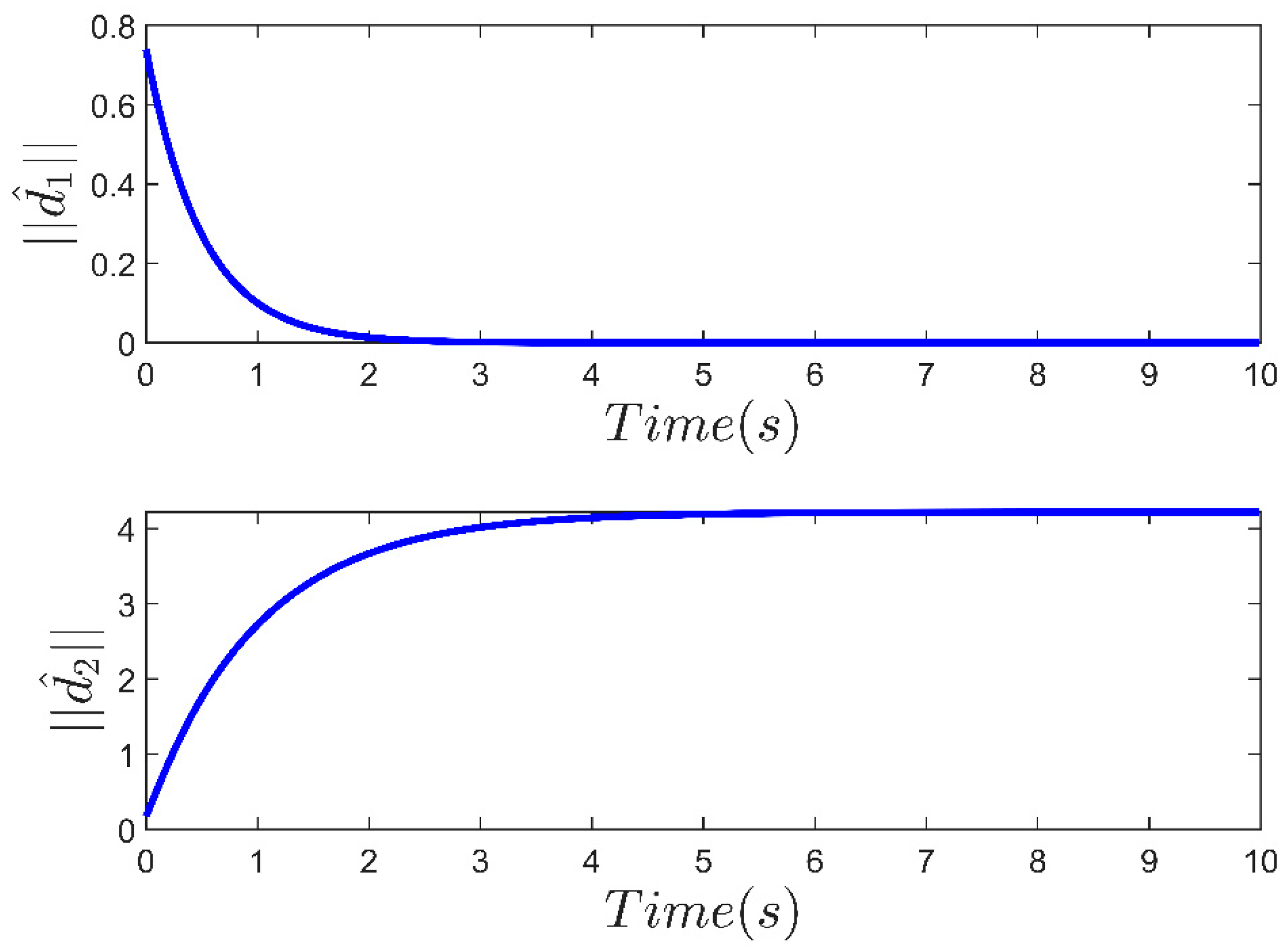
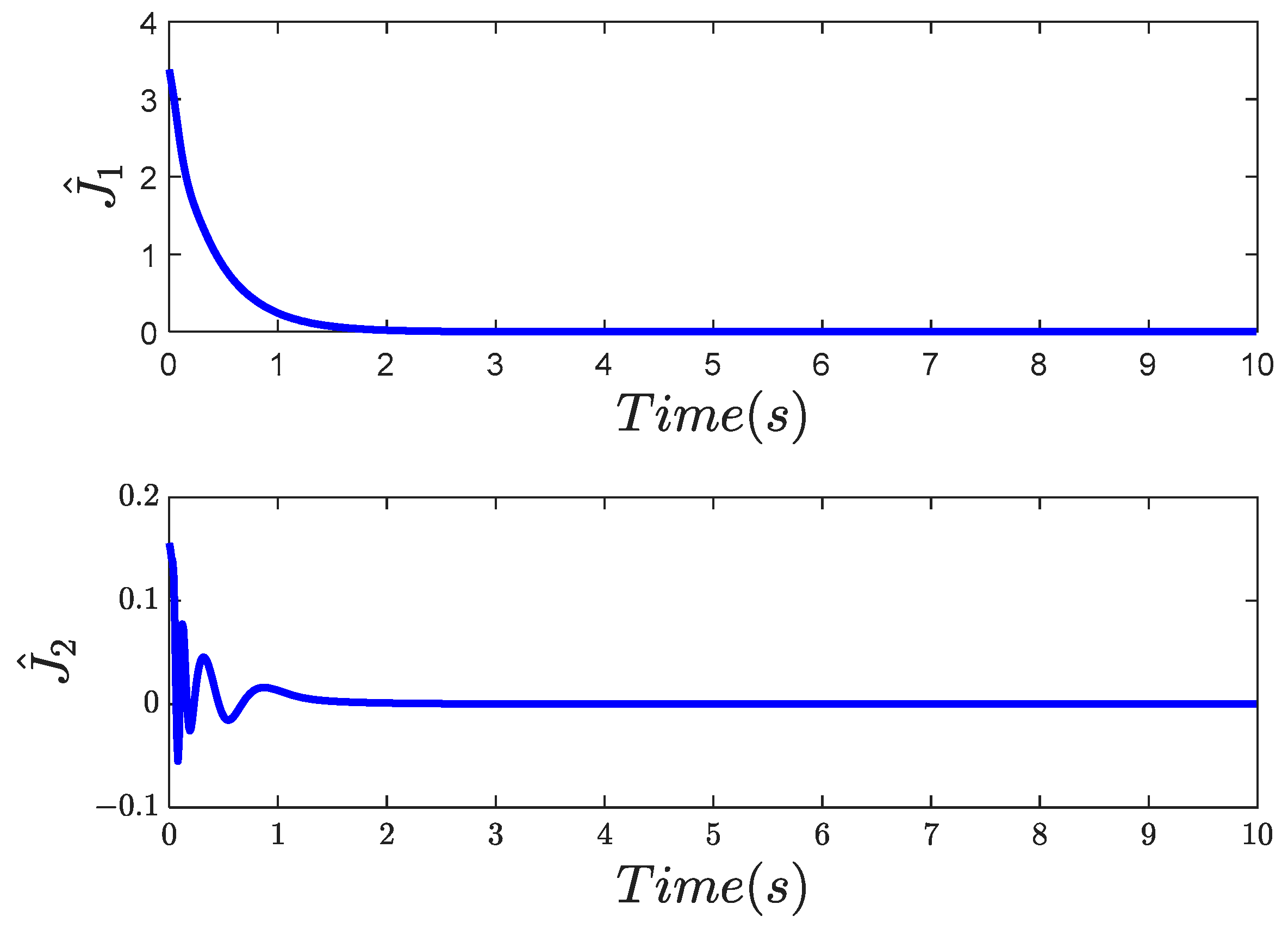
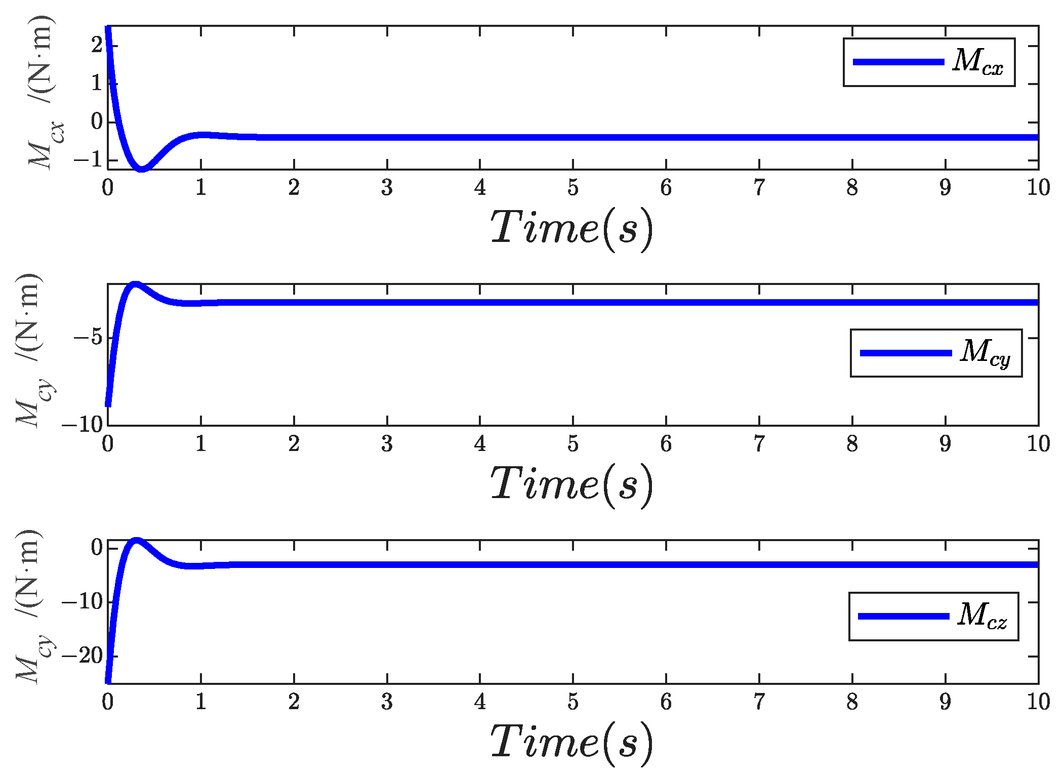
The simulation results are given in Figure 2, Figure 3, Figure 4, Figure 5 and Figure 6. Figure 2 demonstrates the trajectory tracking performance of the morphing unmanned aircraft’s attitude angles under coupled uncertainties. Obviously, the proposed RL-based adaptive controller achieves convergence within a 0.001-error bound around the desired trajectories. Despite an initial transient overshoot, the intelligent controller can quickly compensate for the uncertainties, exhibiting strong adaptability and robustness. The disturbance estimation and neural network weight estimation signals are shown in Figure 3, Figure 4 and Figure 5, and it can be seen that all signals are bounded. Figure 6 shows the control torque variation curve over time under Case 1.
To verify the advantages of the proposed reinforcement learning adaptive control (RLAC) method and its adaptability, such as speed and stability, the neural network adaptive control (NNAC) [59] method and the adaptive fault-tolerant control (AFTC) [60] method are selected for comparison. These existing adaptive control methods serve as benchmarks to highlight the unique features of the RLAC method. All controllers track identical reference trajectories under the same experimental conditions. The experimental results comprehensively compare the proposed RLAC method with two existing control approaches, AFTC and NNAC methods, are shown in Figure 7 and Figure 8. Table 2 presents the steady-state error and convergence time of the three methods, where convergence time is defined as the time required to complete 90% of the convergence process. In Figure 8, the tracking error is defined as the sum of the two norms of the errors z 1 and z 2 , that is, e = z 1 2 + z 2 2 , which clearly highlights the superiority of the proposed RLAC method.
The results demonstrate that under the same experimental conditions, the AFTC method has limitations. It has a relatively large steady-state error of about 0.25 and a convergence time exceeding 10 s, which means it struggles to precisely track the reference trajectory and reaches a stable state slowly, leading to inefficient system operation.
The NNAC method shows improvements. It can achieve a steady-state error of less than 0.0015, more accurate than the AFTC method. However, it suffers from significant overshoot, which may cause system instability. In contrast, the RLAC method demonstrates remarkable superiority. It has a steady-state error below 0.001, the fastest convergence speed, and can rapidly adapt to changing environments. In terms of tracking performance, it outperforms both AFTC and NNAC methods in speed and stability. Consequently, the RLAC method offers significant advantages over AFTC and NNAC methods, making it a more promising choice for practical control applications.

5. Conclusions

The RL-based adaptive fault-tolerant control method proposed in this paper effectively solves the control problem for a class of morphing unmanned aircraft under mismatched disturbances and coupled uncertainties. The aircraft’s uncertainties are modeled as a non-affine second-order nonlinear system, and the non-affine structure is handled by introducing an auxiliary integral system. The unknown functions are evaluated by the introduced RL algorithms, and the control actions are adjusted by the developed RL-based adaptive laws. The filtering errors and disturbances are compensated by adopting a disturbance boundary estimator. The RL-based adaptive fault-tolerant control method has been successfully designed by integrating RL, disturbance estimation, and finite-time theory. It is proven by the Lyapunov function that the system has finite-time stability and all signals are bounded. Numerical simulations verify the effectiveness and superiority of this method. In the future, this method is expected to be extended to aircraft models, considering various factors in the actual flight environment.

Author Contributions

W.R.: writing–review and editing, writing–original draft, visualization, methodology, software, conceptualization, and funding acquisition. Y.W.: writing—review and editing, supervision. C.W.: writing—review and editing, visualization. Z.W.: writing—review and editing, visualization. All authors have read and agreed to the published version of the manuscript.

Funding

This work is supported in part by the Guizhou Provincial Science and Technology Projects ([2025] 049).

Data Availability Statement

The raw data supporting the conclusions of this article will be made available by the authors on request.

Conflicts of Interest

The authors declare no conflicts of interest.

References

  1. Jha, A.K.; Kudva, J.N. Morphing Unmanned aircraft Concepts, Classifications, and Challenges. In Smart Structures and Materials 2004: Industrial and Commercial Applications of Smart Structures Technologies; Society of Photo Optical: Bellingham, WA, USA, 2004; Volume 5388, pp. 213–224. [Google Scholar]
  2. Chu, L.; Li, Q.; Gu, F.; Du, X.; He, Y.; Deng, Y. Design, Modeling, and Control of Morphing Aircraft: A Review. Chin. J. Aeronaut. 2022, 35, 220–246. [Google Scholar] [CrossRef]
  3. Yu, Z.; Zang, Y.; Jiang, B. PID-type fault-tolerant prescribed performance control of fixed-wing UAV. J. Syst. Eng. Electron. 2021, 32, 1053–1061. [Google Scholar]
  4. Noordin, A.; Mohd Basri, M.A.; Mohamed, Z.; Mat Lazim, I. Adaptive PID controller using sliding mode control approaches for quadrotor UAV attitude and position stabilization. Arab. J. Sci. Eng. 2021, 46, 963–981. [Google Scholar] [CrossRef]
  5. Wang, P.; Chen, H.; Bao, C.; Tang, G. Review on Modeling and Control Methods of Morphing Vehicle. J. Astronaut. 2022, 43, 853–865. [Google Scholar]
  6. Ameduri, S.; Concilio, A. Morphing Wings Review: Aims, Challenges, and Current Open Issues of a Technology. Proc. Inst. Mech. Eng. Part C J. Mech. Eng. Sci. 2023, 237, 4112–4130. [Google Scholar] [CrossRef]
  7. Shardul, G. Study of Various Trends for Morphing Wing Technology. J. Comput. Methods Sci. Eng. 2021, 21, 613–621. [Google Scholar] [CrossRef]
  8. He, H.; Wang, P. Integrated Guidance and Control Method for High-Speed Morphing Wing Aircraft. Acta Aeronaut. Astronaut. Sin. 2024, 45, 299–312. [Google Scholar]
  9. Zhang, H.; Wang, P.; Tang, G.; Bao, W. Fixed-Time Sliding Mode Control for Hypersonic Morphing Vehicles via Event-Triggering Mechanism. Aerosp. Sci. Technol. 2023, 140, 108458. [Google Scholar] [CrossRef]
  10. Abouheaf, M.; Mailhot, N.Q.; Gueaieb, W.; Spinello, D. Guidance Mechanism for Flexible-Wing Aircraft Using Measurement-Interfaced Machine-Learning Platform. IEEE Trans. Instrum. Meas. 2020, 69, 4637–4648. [Google Scholar] [CrossRef]
  11. Lee, J.; Kim, Y. Neural Network-Based Nonlinear Dynamic Inversion Control of Variable-Span Morphing Aircraft. Proc. Inst. Mech. Eng. Part G J. Aerosp. Eng. 2020, 234, 1624–1637. [Google Scholar] [CrossRef]
  12. Irfan, S.; Zhao, L.; Ullah, S.; Javaid, U.; Iqbal, S. Differentiator- and Observer-Based Feedback Linearized Advanced Nonlinear Control Strategies for an Unmanned Aerial Vehicle System. Drones 2024, 8, 527. [Google Scholar] [CrossRef]
  13. Lee, H.; Kim, S.; Kim, Y. Actor-Critic-Based Optimal Adaptive Control Design for Morphing Aircraft. IFAC Pap. 2020, 53, 14863–14868. [Google Scholar] [CrossRef]
  14. Zhou, Y.; Wang, P.; Tang, G.; Chen, H. Disturbance Observer-Based Prescribed Performance Control for Morphing Aircraft. Tactical Missile Technol. 2024, 4, 72–82. [Google Scholar]
  15. Hu, H.; Li, Y.; Yi, W.; Wang, Y.; Qu, F.; Wang, X. Event-Triggered Neural Network-Based Adaptive Control for a Class of Uncertain Nonlinear Systems. J. Circuits Syst. Comput. 2021, 30, 15. [Google Scholar] [CrossRef]
  16. Yuan, F.; Liu, Y.-J.; Liu, L.; Lan, J. Adaptive Neural Network Control of Non-Affine Multi-Agent Systems with Actuator Fault and Input Saturation. Int. J. Robust. Nonlinear Control 2024, 34, 3761–3780. [Google Scholar] [CrossRef]
  17. Anderson, R.B.; Marshall, J.A.; L’Afflitto, A.; Dotterweich, J.M. Model Reference Adaptive Control of Switched Dynamical Systems with Applications to Aerial Robotics. J. Intell. Robot. Syst. 2020, 100, 1265–1281. [Google Scholar] [CrossRef]
  18. Qi, W.; Teng, J.; Cao, J.; Yan, H.; Cheng, J. Improved Model Reference-Based Adaptive Nonlinear Dynamic Inversion for Fault-Tolerant Flight Control. Int. J. Robust. Nonlinear Control 2023, 33, 10328–10359. [Google Scholar] [CrossRef]
  19. Li, Y.; Liu, X.; Ming, R.; Li, K.; Zhang, W. Dynamic Protocol-Based Control for Hidden Stochastic Jump Multiarea Power Systems in Finite-Time Interval. IEEE Trans. Cybern. 2025, 55, 1486–1496. [Google Scholar]
  20. Li, G.; Peng, C.; Cao, Z. Finite-time bounded asynchronous sliding-mode control for T-S fuzzy time-delay systems via event-triggered scheme. Fuzzy Sets Syst. 2025, 514, 109400. [Google Scholar] [CrossRef]
  21. Yu, C.; Jiang, J.; Wang, S.; Han, B. Fixed-Time Adaptive General Type-2 Fuzzy Logic Control for Air-Breathing Hypersonic Vehicle. Trans. Inst. Meas. Control 2021, 43, 2143–2158. [Google Scholar] [CrossRef]
  22. Hernández-González, O.; Targui, B.; Valencia-Palomo, G.; Guerrero-Sánchez, M.E. Robust cascade observer for a disturbance unmanned aerial vehicle carrying a load under multiple time-varying delays and uncertainties. Int. J. Syst. Sci. 2024, 55, 1056–1072. [Google Scholar] [CrossRef]
  23. Hernández-González, O.; Ramírez-Rasgado, F.; Farza, M.; Guerrero-Sánchez, M.-E.; Astorga-Zaragoza, C.-M.; M’Saad, M.; Valencia-Palomo, G. Observer for Nonlinear Systems with Time-Varying Delays: Application to a Two-Degrees-of-Freedom Helicopter. Aerospace 2024, 11, 206. [Google Scholar] [CrossRef]
  24. Qu, C.; Cheng, L.; Gong, S.; Huang, X. Dynamic-Matching Adaptive Sliding Mode Control for Hypersonic Vehicles. Aerosp. Sci. Technol. 2024, 149, 109159. [Google Scholar] [CrossRef]
  25. Zhao, Y.; Ma, Y. Adaptive Event-Triggered Finite-Time Sliding Mode Control for Singular T–S Fuzzy Markov Jump Systems with Asynchronous Modes. Commun. Nonlinear Sci. Numer. Simul. 2023, 126, 107465. [Google Scholar] [CrossRef]
  26. Shi, X.; Li, Y.; Liu, Q.; Lin, K.; Chen, S. A Fully Distributed Adaptive Event-Triggered Control for Output Regulation of Multi-Agent Systems with Directed Network. Inf. Sci. 2023, 626, 60–74. [Google Scholar] [CrossRef]
  27. Abbas, M.; Sadati, S.H.; Khazaee, M. Fault-Tolerant Control Design Based on Observer-Switching and Adaptive Neural Networks for Maneuvering Aircraft. J. Braz. Soc. Mech. Sci. Eng. 2024, 46, 14689–14698. [Google Scholar] [CrossRef]
  28. Zhao, L.; Wang, L.; Cao, Y.; Yang, Y.; Wen, S. Learning-Based Fault-Tolerant Control With High-Order Control Barrier Functions. IEEE Trans. Autom. Sci. Eng. 2025, 22, 694. [Google Scholar] [CrossRef]
  29. Ma, J.; Peng, C. Adaptive Model-Free Fault-Tolerant Control Based on Integral Reinforcement Learning for a Highly Flexible Aircraft with Actuator Faults. Aerosp. Sci. Technol. 2021, 119, 107204. [Google Scholar] [CrossRef]
  30. Liu, Y.; Jing, Y.; Liu, X.; Li, X. Survey on Finite-Time Control for Nonlinear Systems. Control Theory Appl. 2020, 37, 1–12. [Google Scholar]
  31. Guo, F.; Zhang, W.; Lv, M.; Zhang, R. Fault-Tolerant Tracking Control of Hypersonic Vehicle Based on a Universal Prescribe Time Architecture. Drones 2024, 8, 295. [Google Scholar] [CrossRef]
  32. Bingö, Z.; Güzey, H. Finite-Time Neuro-Sliding-Mode Controller Design for Quadrotor UAVs Carrying Suspended Payload. Drones 2022, 6, 311. [Google Scholar] [CrossRef]
  33. Rang, E.R. Isochrone Families for Second-Order Systems. IEEE Trans. Automat. Contr. 1963, 8, 64–65. [Google Scholar] [CrossRef]
  34. Chen, X.; Zhang, X. Output-Feedback Control Strategies of Lower-Triangular Nonlinear Nonholonomic Systems in Any Prescribed Finite Time. Int. J. Robust Nonlinear Control 2019, 29, 904–918. [Google Scholar] [CrossRef]
  35. Zhou, T.; Liu, S.; Liu, C. Finite-Time Prescribed Performance Adaptive Fuzzy Control for Nonlinear Systems with Unknown Virtual Control Coefficients. In Proceedings of the 2021 International Conference on Security, Pattern Analysis, and Cybernetics (SPAC), Chengdu, China, 18–20 June 2021; pp. 7–12. [Google Scholar]
  36. Kang, B.; Li, Y. Adaptive Finite-Time Stabilization of High-Order Stochastic Nonlinear Systems with Unknown Control Direction. In Proceedings of the Conference Digest—2021 International Conference on Security, Pattern Analysis, and Cybernetics (SPAC), Chengdu, China, 18–20 June 2021; pp. 150–155. [Google Scholar]
  37. Zhu, W.; Zong, Q.; Zhang, X.; Liu, W. Disturbance Observer-Based Multivariable Finite-Time Attitude Tracking for Flexible Spacecraft. In Proceedings of the Chinese Control Conference (CCC), Chongqing, China, 28–30 July 2020; Volume 2020, pp. 1772–1777. [Google Scholar]
  38. Wang, H.; Kang, S.; Feng, Z. Finite-Time Adaptive Fuzzy Command Filtered Backstepping Control for a Class of Nonlinear Systems. Int. J. Fuzzy Syst. 2019, 21, 2575–2587. [Google Scholar] [CrossRef]
  39. Zhao, Q.; Duan, G. Concurrent Learning Adaptive Finite-Time Control for Spacecraft with Inertia Parameter Identification under External Disturbance. IEEE Trans. Aerosp. Electron. Syst. 2021, 57, 3691–3704. [Google Scholar] [CrossRef]
  40. Bu, X.; Luo, R.; Lei, H. Chattering-avoidance discrete-time fuzzy control with finite-time preselected qualities. IEEE Trans. Fuzzy Syst. 2024, 33, 997–1008. [Google Scholar] [CrossRef]
  41. Bu, X.; Luo, R.; Lei, H. Fuzzy-neural intelligent control with fixed-time pre-configured qualities for electromechanical dynamics of electric vehicles motors. IEEE Trans. Intell. Transp. Syst. 2024, 26, 1193–1202. [Google Scholar] [CrossRef]
  42. Luo, R.; He, G.; Li, Y.; Bu, X.; Li, Q. Appointed-time Fuzzy Fault-tolerant Control of Hypersonic Flight Vehicles with Flexible Predefined Behaviors. IEEE Trans. Autom. Sci. Eng. 2025, 22, 13995–14007. [Google Scholar] [CrossRef]
  43. Lin, X.; Shi, X.; Li, S. Adaptive Tracking Control for Spacecraft Formation Flying System via Modified Fast Integral Terminal Sliding Mode Surface. IEEE Access 2020, 8, 198357–198367. [Google Scholar] [CrossRef]
  44. Wang, Q.; Wang, T.; Dong, C.; Jiang, W. Chained Smooth Switching Control for Morphing Aircraft. Control Theory Appl. 2015, 32, 949–954. [Google Scholar]
  45. Cheng, H.; Fu, W.; Dong, C.; Wang, Q.; Hou, Y. Asynchronously Finite-Time H∞ Control for Morphing Aircraft. Trans. Inst. Meas. Control 2018, 40, 4330–4344. [Google Scholar] [CrossRef]
  46. Chen, H.; Wang, P.; Tang, G. Attitude Control Scheme for Morphing Vehicles with Output Error Constraints and Input Saturation. Acta Aeronaut. Astronaut. Sin. 2023, 44, 408–419. [Google Scholar]
  47. Sheng, H. Research on Strong Robust Control for Flexible Hypersonic Morphing Vehicle. Master’s Thesis, National University of Defense Technology, Changsha, China, 2021. [Google Scholar]
  48. Liang, X.; Wang, Q.; Xu, B.; Dong, C. Back-stepping fault-tolerant control for Morphing Unmanned aircraft based on fixed-time observer. Int. J. Control Autom. Syst. 2021, 19, 3924–3936. [Google Scholar] [CrossRef]
  49. Wu, Z.; Lu, J.; Zhou, Q.; Shi, J. Modified adaptive neural dynamic surface control for Morphing Unmanned aircraft with input and output constraints. Nonlinear Dyn. 2017, 87, 2367–2383. [Google Scholar] [CrossRef]
  50. Emmanuel, S.A.; Sun, R. Approximation-free prescribed performance control for Nonlinear morphing missile System. Int. J. Eng. Appl. Sci. 2016, 3, 257584. [Google Scholar]
  51. Wang, Z.; Chang, Y.; Qiu, Y.; Xing, X. RL-based adaptive control for a class of non-affine uncertain stochastic systems with mismatched disturbances. Commun. Nonlinear Sci. Numer. Simul. 2024, 138, 108191. [Google Scholar] [CrossRef]
  52. Zhang, J.; Wang, S.; Zhou, P.; Zhao, L.; Li, S. Novel Prescribed Performance-Tangent Barrier Lyapunov Function for Neural Adaptive Control of the Chaotic PMSM System by Backstepping. Int. J. Electr. Power Energy Syst. 2020, 121, 105991. [Google Scholar] [CrossRef]
  53. Wang, F.; Chen, B.; Liu, X.; Lin, C. Finite-time adaptive fuzzy tracking control design for nonlinear systems. IEEE Trans. Fuzzy Syst. 2017, 26, 1207–1216. [Google Scholar] [CrossRef]
  54. Qian, C.; Lin, W. Non-Lipschitz Continuous Stabilizers for Nonlinear Systems with Uncontrollable Unstable Linearization. Syst. Control Lett. 2001, 42, 185–200. [Google Scholar] [CrossRef]
  55. Li, M.; Zhang, J.; Li, S.; Wu, F. Adaptive Finite-Time Fault-Tolerant Control for the Full-State-Constrained Robotic Manipulator with Novel Given Performance. Eng. Appl. Artif. Intell. 2023, 125, 106650. [Google Scholar] [CrossRef]
  56. Wei, Y.; Zhou, P.; Liang, Y.; Wang, Y.; Duan, D. Adaptive finite-time neural backstepping control for multi-input and multi-output state-constrained nonlinear systems using tangent-type nonlinear mapping. Int. J. Robust Nonlinear Control 2020, 30, 5559–5578. [Google Scholar] [CrossRef]
  57. Wang, F.; Chen, B.; Lin, C.; Zhang, J.; Meng, X. Adaptive Neural Network Finite-Time Output Feedback Control of Quantized Nonlinear Systems. IEEE Trans. Cybern. 2018, 48, 1839–1848. [Google Scholar] [CrossRef]
  58. Zhang, J.; Wang, S.; Li, S.; Zhou, P. Adaptive Neural Dynamic Surface Control for the Chaotic PMSM System with External Disturbances and Constrained Output. Recent Adv. Electr. Electron. Eng. 2020, 13, 894–905. [Google Scholar]
  59. Wu, J.; Sun, Y.; Zhao, Q.; Wu, Z.-G. Adaptive neural asymptotic tracking control for a class of stochastic non-strict-feedback switched systems. J. Frankl. Inst. 2018, 359, 1274–1297. [Google Scholar] [CrossRef]
  60. Chen, K.; Zhu, S.; Wei, C.; Xu, T.; Zhang, X. Output constrained adaptive neural control for generic hypersonic vehi-cles suffering from non-affine aerodynamic characteristics and stochastic disturbances. Aerosp. Sci. Technol. 2021, 111, 106469. [Google Scholar] [CrossRef]
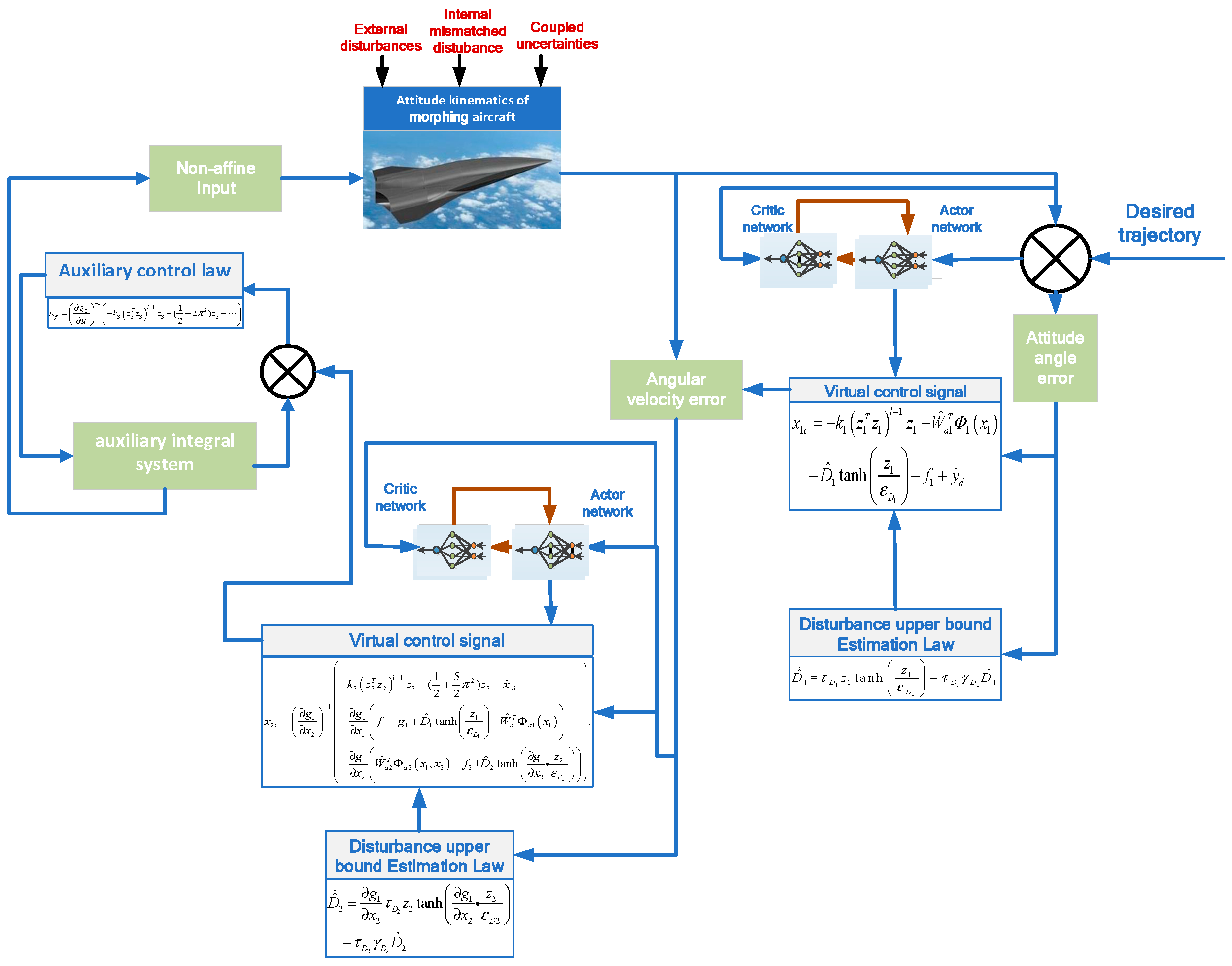
Figure 1. The controller structure.
Drones 09 00562 g001
Figure 2. Attitude angle trajectories under three cases.
Drones 09 00562 g002
Figure 3. Disturbance norm estimation under Case 1.
Drones 09 00562 g003
Figure 4. Actor network weight norm estimation under Case 1.
Drones 09 00562 g004
Figure 5. Penalty functions estimation under Case 1.
Drones 09 00562 g005
Figure 6. Control torques under Case 1.
Drones 09 00562 g006
Figure 7. Comparison of tracking performance of three methods under Case 1.
Drones 09 00562 g007
Figure 8. Comparison of tracking errors of three methods under Case 1.
Drones 09 00562 g008
Table 1. The different parameter values of the morphing unmanned aircraft under three cases.
Cases Δ f 1 d 1 t Δ f 2 d 2 t
Case 1 θ ˙ = 0.007 / s σ ˙ = 0.01 / s , θ = 0 0.01 I b 0.01 M f + 0.01 I b
Case 2 θ ˙ = 0.01 / s σ ˙ = 0.006 / s , θ = 0.03 0.008 I b 0.006 M f + 0.01 I b
Case 3 θ ˙ = 0.005 ° × ( 1 + 0.1 sin ( t ) ) / s σ ˙ = 0.008 ° × ( 1 + 0.1 cos ( t ) ) / s , θ = 0.02 ° 0.004 × ( 1 + 0.1 sin ( t ) ) I b 0.009 M f + 0.01 × ( 1 + 0.1 cos ( t ) ) I f
Table 2. Tracking performance of three methods.
MethodSteady-State Error (Rad)Convergence Time (s)
RLAC0.0038, 0.0024, 0.000870.79, 0.66, 0.82
NNAC0.007, 0.0023, 0.0011.43, 4.19, 1.19
AFTC>0.026, >0.025, >0.00265.81, >10, 1.9
Disclaimer/Publisher’s Note: The statements, opinions and data contained in all publications are solely those of the individual author(s) and contributor(s) and not of MDPI and/or the editor(s). MDPI and/or the editor(s) disclaim responsibility for any injury to people or property resulting from any ideas, methods, instructions or products referred to in the content.