1. Introduction
There is a growing need within the aviation community to offer air mobility as a viable alternative for everyday transportation, referred to by various names such as On Demand Mobility (ODM), Urban Air Mobility (UAM), Air Taxi Operations, or Advanced Air Mobility (AAM) [
1,
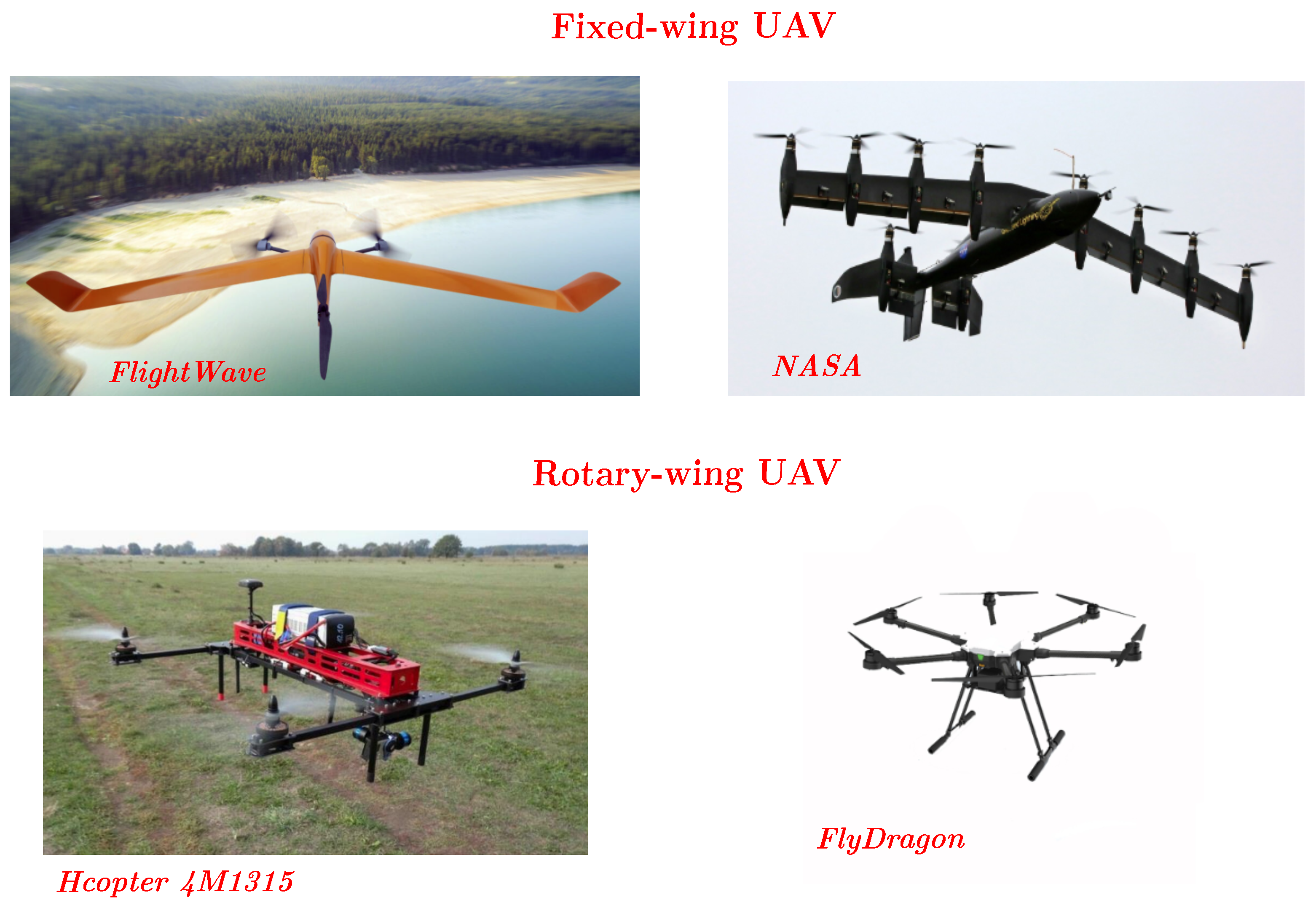
2]. Multi-rotor UAVs (Unmanned Aerial Vehicles) are widely used across various applications, but their increasing operation near humans introduces new challenges (see
Figure 1). While traditional development has focused on performance and endurance, growing concerns around safety, privacy, and particularly noise have emerged. Noise impact remains a key barrier to broader adoption. This study is motivated by the need to reduce UAV noise, and it explores an active noise control strategy to address this issue.
In propeller-driven aircraft, the primary sources of noise are the engine and the propeller, with propeller noise extensively studied in the literature. Aerodynamic propeller noise is broadly categorised into tonal and broadband components. Tonal noise primarily arises from blade thickness and aerodynamic loading, while broadband noise results from turbulent interactions at the trailing edge, leading edge, and flow separation. These mechanisms are typically modelled as distinct pressure fluctuation components corresponding to each source [
7]. Tonal noise commonly occurs at harmonics of the Blade Passing Frequency (BPF) and originates from interactions involving the propeller itself, propeller-to-propeller interactions, propeller–pylon interactions [
8], and propeller–wing configurations [
9,
10]. In contrast, broadband noise is associated with turbulence ingestion and trailing-edge noise mechanisms. Extensive experimental research under both hover and forward flight conditions has examined how propeller design parameters that include tip Mach number, pitch, diameter, and blade number affect aeroacoustic performance [
11,
12]. Experimental data have been meticulously analysed to optimise propeller efficiency by evaluating key aerodynamic parameters and the effects of Reynolds number on aerodynamic scaling [
13]. Given the frequent operation of UAVs in urban environments, identifying effective noise control strategies is critically important. Recent advancements have classified noise mitigation techniques for multi-rotor platforms into passive and active methods. Passive control strategies focus on optimizing the rotor blade design, such as blade shape, trailing edge, and airfoil distribution, to reduce noise [
14,
15], while active control methods, including Active Noise Cancellation (ANC), generate antinoise to neutralize unwanted sound [
16]. Moreover, synchronising acoustic sources by adjusting the relative phase of rotors to manage noise directionality has emerged as a promising approach in multi-rotor configurations [
17,
18,
19,
20,
21].
The characteristics of propeller-generated sound waves include frequency (
f), wavelength (
), amplitude (
A), and speed (
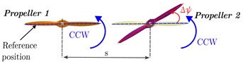
v). Destructive and constructive interference are phenomena that occur when multiple sound waves interact. In constructive interference, two sound waves with similar frequencies and phases align, resulting in an increase in overall amplitude, which amplifies the sound (see
Figure 2). Conversely, destructive interference occurs when two waves with similar frequencies but opposite phases combine, leading to a reduction or cancellation of their amplitudes, effectively diminishing or eliminating the sound. These mechanisms are fundamental to noise control strategies, such as the phase synchronisation method, which uses destructive interference to reduce noise levels. Studies have demonstrated that adjusting the relative phase between propellers can significantly alter acoustic emissions at low frequencies, achieving up to a 6 dB reduction with three-bladed propellers [
17] and up to a 10 dB variation depending on the phase angle [
22]. Moreover, both experimental and theoretical investigations have shown that phase control can yield a 4–5 dB SPL reduction at the first BPF [
23] and an 8 dB reduction under static conditions at 3000 rpm with a 90° phase difference [
24]. Turhan et al. [
25] examined noise suppression in DEP systems under static thrust and inflow conditions using electronic propeller synchronisation. They found that a relative phase angle of
yielded maximum noise reduction, achieving an 8 dB decrease at the first BPF and a 2 dB reduction in OASPL under static thrust (
), as well as approximately a 24 dB reduction at the first BPF and a 6 dB reduction in OASPL under inflow conditions (
) compared to
. A numerical synchrophasing study shows that noise levels can be reduced by more than 20 dB in several one-third-octave bands and by up to 7 dB overall between the rotors, without compromising performance [
26]. A numerical study of a three-propeller arrangement shows that acoustic interference among the propellers is essential for reducing the blade passing frequency harmonic tone. The best result appears at a phase offset of 30 degrees, where destructive interference between the blades almost eliminates sound radiation along the flow direction, a direction otherwise dominated by aerodynamic interactions [
27].
Studies show that noises with tonal components tend to increase annoyance levels in urban environments [
29]. Although Zwicker’s model reliably estimates annoyance for a variety of noise types [
30], it may underpredict the annoyance caused by strongly tonal sounds because it does not consider the influence of tonality. To date, no study has fully linked the effect of phase synchronisation to perceived sound quality. Gwak et al. [
31] demonstrated that loudness, sharpness, and fluctuation strength are strong predictors of UAV noise annoyance, while Torija et al. [
32] investigated how rotor axial spacing in contra-rotating systems affects various psychoacoustic annoyance models and sound quality metrics (SQMs) such as loudness, sharpness, tonality, fluctuation strength, roughness, and impulsiveness, thereby relating specific design configurations to human auditory responses.
Building on previous findings, it is important to understand how additional parameters further influence noise generation and mitigation in UAVs. Parameters such as tip-to-tip separation distance, the number of blades, and blade geometry play a key role in this process. This investigation is particularly significant given the limited research linking the aeroacoustic and psychoacoustic characteristics of these systems. This comprehensive study aims to determine how noise reduction varies with different parameters when phase synchronisation is applied. The investigation focuses on the tonal noise generated by two adjacent propellers in a UAV configuration. A psychoacoustic analysis, similar to those in previous research, is then conducted to assess the impact of altering the relative phase angle on noise perception. Ultimately, this work provides initial insights into UAV propeller noise and lays the foundation for future studies that may explore perception-driven control strategies.
2. Methods
All the measurements presented in this study were conducted at the aeroacoustic facility located within the wind tunnel at the University of Bristol. The test rig was installed in the anechoic chamber, where the internal structure of the collector is acoustically treated to mitigate sound reflections during acoustic measurements. The anechoic chamber is capable of providing accurate measurements down to 160 Hz, in accordance with the ISO 3745 standardized [
33] testing procedure for both pure tone and broadband noise. The wind tunnel’s exit nozzle, with dimensions of
m by
m and a contraction ratio of
, facilitates stable airflow speeds ranging from 5 m/s to 40 m/s, with a turbulence intensity of approximately
in the anechoic environment [
34].
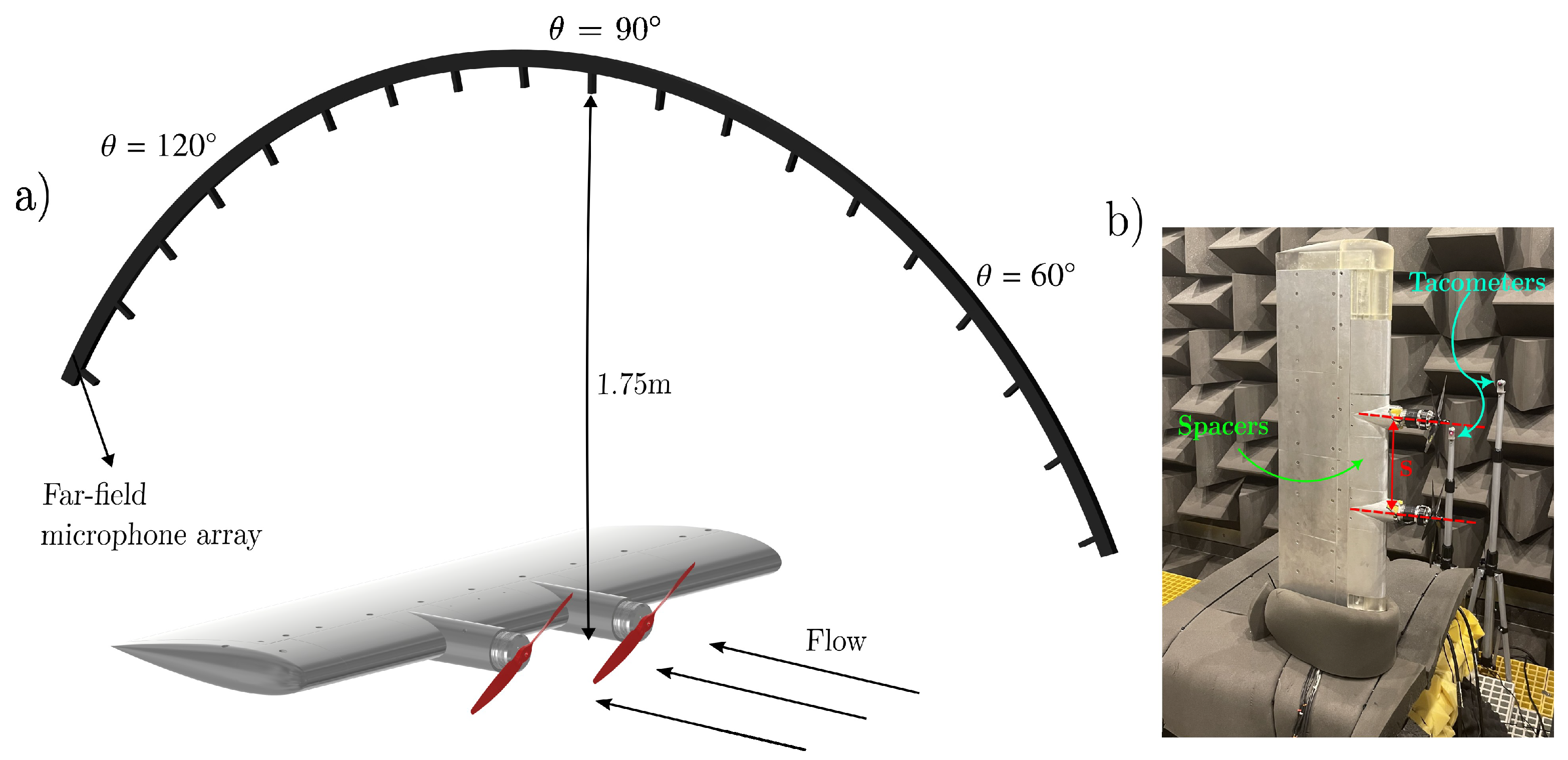
The experimental setup, illustrated in
Figure 3, consists of two propulsion units with propellers mounted on a wing. The wing was designed using a NACA0018 profile, with a chord length of
m, a span of
m, and fabricated from a 6000-series aluminium alloy. The propellers were positioned 150 mm downstream from the wing’s trailing edge to the propeller’s leading edge. They were placed approximately
m downstream from the nozzle exit, aligned with the tunnel’s free-stream flow. Each propeller is powered by a 540 kV AT4125 T-motor (T-Motor, Nanchang, China), capable of a maximum continuous power output of
kW. To precisely track the phase angle of the propeller blades, a 12-bit RLS
® RE36IC incremental encoder (RLS, Komenda, Slovenia) is used, providing an accuracy of
.
A far-field microphone array was arranged such that the microphone at
was positioned
m directly above the wing’s center, equidistant from both propellers. The array consisted of 23 G.R.A.S 40PL microphones
inch (G.R.A.S Sound and Vibration, Holte, Denmark), spaced at
intervals, covering polar angles from
to
. These microphones operated across a frequency range of 10 Hz–20 kHz, with a dynamic range up to 142 dB and accuracy of
dB. Data were sampled at
Hz and recorded over
s using a National Instruments PXIe-4499 module (National Instruments, Austin, TX, USA). Time–domain signals were processed using MATLAB R2022a’s Pwelch method [
35] to produce frequency–domain spectra with a 1 Hz resolution. The sound pressure level (SPL) was then computed using the following equation:
where
represents the power spectral density of the measured acoustic pressure and
is the reference acoustic pressure (equal to 20
Pa). The acoustic signal processing was performed without the application of standard frequency-weighting filters (A-, B-, or C-weighting). All SPL values and psychoacoustic quantities were derived from unweighted signals to maintain consistency across the full frequency spectrum of interest.
Table 1 and
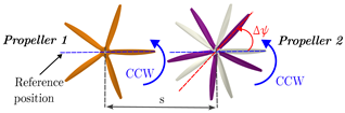
Table 2 define the relative phase angle (
) for the two-propeller configurations, along with the geometric and test parameters of the experimental setup. The relative phase angle refers to the angular offset between the blades of the two propellers. For baseline conditions, both propellers were initially aligned horizontally along the wing span, setting
. Propeller 1, designated as the main propeller, was set to rotate counterclockwise with an initial phase of
. Propeller 2, referred to as the slave propeller, also rotated counterclockwise (co-rotation configuration) relative to the incoming flow. The blade position of Propeller 2 was adjusted to generate various relative phase angles, while Propeller 1 remained fixed at its initial position. For the two-bladed configuration, seven phase angles (
) were examined, ranging from
to
in
increments (see
Table 1). In the case of the five-bladed configuration, three phase angles were investigated, from
to
in
increments (see
Table 2).
Aeroacoustic measurements were performed at a wind tunnel velocity of 9 m/s, corresponding to an advance ratio of
, with both two-bladed propellers co-rotating at 5000 rpm. The advance ratio is a non-dimensional term defined as
where
V is the free-stream inflow velocity in m/s,
n is the rotational speed in revolutions per second, and
D is the propeller diameter in meters. The rotational speed is set to 4000 rpm for the five-bladed propellers due to the maximum current limit of the control system.
The center-to-center distance between the propellers (
s) was adjusted by inserting spacers between the propulsion units at the wing’s leading edge (see
Figure 3b). This approach allowed for the propeller separation to be modified, enabling testing of various configurations. The separation distance was varied from 1% to 5% of the propeller diameter. The propellers were designed using a Clark-Y airfoil section and manufactured from composite carbon fiber/epoxy materials. In this study, we used pairs of two-bladed propellers with a diameter of
, testing two different pitch values (
and
), and a pair of five-bladed propellers with a pitch-to-diameter ratio of
.
2.1. Phase Synchronization Control System
The phase angle control system design was tailored to achieve accurate synchronization and independent control of propeller phase angles. Each propeller operates with a dedicated motor and controller, allowing for separate revolutions per minute (RPM) and phase adjustments. This system supports both fixed reference positions and user-defined offsets, ensuring flexible control under various operational conditions. The synchronization mechanism dynamically adjusts to changes in propeller speed for optimal performance, even at high RPMs, maintaining consistent angular relationships between propellers (2.5 rpm) [
25].
The system block diagram in
Figure 4 shows the control architecture developed for precise propeller synchronization and noise reduction. It uses a field-oriented control strategy implemented on a TI LAUNCHXL-F280049C board with a BOOSTXL-3PhGaNInv three-phase converter operating at 100 kHz. A 2000-count quadrature encoder provides blade position feedback for real-time control. The architecture consists of two feedback loops: an inner speed loop for regulating RPM and rejecting disturbances, and an outer position loop for maintaining phase alignment through small corrective inputs. Position and speed feedback loops, supported by high-bandwidth current control, enable precise disturbance rejection and quick response. At an operating speed of 5000 rpm, the positional error consistently remains below
, and the peak-to-peak speed variation is less than 0.05% [
25].
2.2. Wavelet Transform
To better understand the impact of phase synchronization, a high-resolution time–frequency analysis using wavelet scalograms was employed. This approach is especially effective for analyzing the first blade-passing frequency (BPF) across both time and frequency domains. The far-field acoustic pressure data are represented using the Wavelet-based Sound Pressure Level (WSPL), expressed as
where
is the Wavelet power spectral density (WPSD). The wavelet coefficient
can be derived from the continuous wavelet transform (CWT), which measures the local characteristics of the acoustic pressure
p at dilation (or scaling)
a and translation (or position)
b [
36].
In this study, the CWT was employed to analyze the time–frequency characteristics of the far-field microphone signals, particularly focusing on the first BPF. The CWT allows for the decomposition of the acoustic signal into time-localized frequency components by convolving it with a set of scaled and translated versions of a base function, known as the mother wavelet [
37]. We selected the Morlet wavelet as the mother function due to its suitability for resolving harmonic structures in tonal noise, such as those generated by rotating blades. The Morlet wavelet provides a good compromise between time and frequency resolution, making it ideal for detecting and tracking the evolution of tonal features over time. The wavelet scalogram, which represents the squared magnitude of the CWT coefficients, was used to construct a WSPL map. This approach enables the identification of time-localized acoustic features and provides a deeper understanding of phase synchronization effects across different frequencies.
2.3. Psychoacoustic Analysis
Several sound quality metrics (SQMs) are used to evaluate psychoacoustic annoyance, including loudness (
N), sharpness (
S), fluctuation strength (
), roughness (
R), tonality (
T), and impulsiveness (
I). Loudness, based on the ISO 532-3 model and calculated in sones, reflects perceived sound intensity across the full auditory spectrum [
30]. Sharpness (in acum), derived from the same model with Aures weighting, captures the perceived high-frequency content of a sound. Fluctuation strength (in vacil) and roughness (in asper) represent slow and fast temporal modulations, respectively, and are calculated using the ECMA-418-2 and Sottek hearing models [
38]. Tonality (in TU) quantifies the prominence of tonal components, while impulsiveness (in IU) captures the perception of sudden sound changes, both also based on Sottek’s model.
Torija et al. [
32] conducted an extensive experimental study on rotor noise, incorporating hearing tests using scaled noise signatures derived from their measurements. Based on their empirical findings, they developed an improved psychoacoustic annoyance (PA) model that incorporates the previously discussed sound quality metrics (SQMs) [
39]. The PA model is expressed as
where
represents the 5th percentile of the loudness metric. The factors
and
account for sharpness and the integrated contributions of fluctuation strength and roughness, respectively, as described by Zwicker and Fastl [
30]. Additionally,
and
correspond to the tonality [
40] and impulsiveness factors. The impulsiveness factor,
, is specifically defined as
All SQMs are calculated using their 5th percentile values to determine these factors. The
coefficients in the model are determined through a non-linear regression analysis, with reported annoyance as the dependent variable and the SQM-derived factors as independent variables. The values of these coefficients are
This PA model provides a robust framework for predicting psychoacoustic annoyance by incorporating the key SQMs—loudness, sharpness, fluctuation strength, roughness, tonality, and impulsiveness—offering an enhanced understanding of noise perception and annoyance in rotorcraft and aerial vehicle systems.
3. Results
The acoustic behavior of phase-synchronized propellers is examined using the Continuous Wavelet Transform (CWT), which enables detailed time–frequency analysis of microphone signals. Unlike Fourier Transform, CWT captures both frequency content and its temporal evolution, allowing for the investigation of transient acoustic features. In this study, CWT is applied to isolate time-localized fluctuations at the first blade-passing frequency (BPF), using a wavelet basis derived from translations and dilations of a mother wavelet function [
41].
Figure 5 displays the contour plots of the wavelet coefficient modulus (
) for two-bladed propellers with
, as measured by the far-field microphone at
. The analysis was conducted for an advance ratio of
, with a center-to-center distance of
, and four relative phase angles,
,
,
and
, at a constant rotational speed of 5000 rpm. To highlight the influence of relative phase angles on the wavelet coefficient behavior at the first BPF, the results are presented for a focused time window of 0.04 s. Initial observations suggest that the wavelet coefficients at the first BPF reveal drastically different behavior as the relative phase angle,
, is increased. The highest wavelet coefficient is observed at a relative phase of
, as shown in
Figure 5a. At
, the tone exhibits a relatively consistent presence over time, signifying an almost constant-amplitude emission of the BPF tone. However, as the relative phase angle is increased to
, this coherence gradually disappears, and the emission of the BPF tone becomes more impulsive, as indicated by short bursts of energy over time. These changes in the temporal characteristics of the BPF tone will impact the perception of this tonal noise, which will be further explored using psychoacoustic indicators in the next section.
The contour maps in
Figure 6 illustrate the far-field noise radiation from the twin-propeller system in the time–frequency plane. The results are presented for several relative phase angles, including
,
,
, and
, using two-bladed propellers (
) with a center-to-center distance of
. The sound pressure level (SPL) related to the microphone position
for the various relative phase angles is calculated and reported. The resolution used for the spectra shown is
, providing a detailed view of the frequency-dependent variations in sound pressure levels. Comparing
Figure 6a with the results for other relative phases in
Figure 6b–d, it is observed that the largest difference between constructive and destructive interference conditions occurs at the first harmonic, where the SPL is reduced by approximately 20 dB. This reduction in sound pressure is a significant finding, as it indicates the effectiveness of phase synchronization in mitigating tonal noise. This reduction in SPL due to phase effects is not only observed at the given relative phase angles, but is also consistent across different velocities [
25]. The far-field interference patterns arise from the coherent interaction of sound waves emitted by phase-synchronized propellers. Depending on the relative phase angle, these waves can either amplify (constructive interference) or cancel each other (destructive interference), resulting in the spatial SPL variations shown in
Figure 5 and
Figure 6. This phenomenon demonstrates the potential of phase synchronization as a passive noise control technique, enabling directional noise reduction by leveraging the wave interference characteristics of the acoustic field.
Shao et al. (2022) [
42] found that phase synchronization is more effective for co-rotating rotors than for counter-rotating ones, offering noise reduction across all directions by significantly lowering sound pressure levels, particularly at low frequencies and blade-passing frequencies. Noise reductions range from 1–5 dB for counter-rotating and 1–11 dB for co-rotating rotor configurations [
42]. Propeller synchronization is ineffective for contra-rotating configurations, as the interference field behaves like a standing wave with amplitude unaffected by blade phase angle [
43]. Therefore, this study focuses exclusively on co-rotating configurations. Similarly, under static thrust conditions, we found that a relative phase angle of
resulted in the highest noise reduction, with an 8 dB decrease at the first BPF at
[
25]. Under the inflow conditions, it is observed that a phase angle of
is the most effective phase angle, similar to the static trust condition, but noise reduction at first BPF is up to 20 dB. Therefore, we extended our investigation to include inflow conditions.
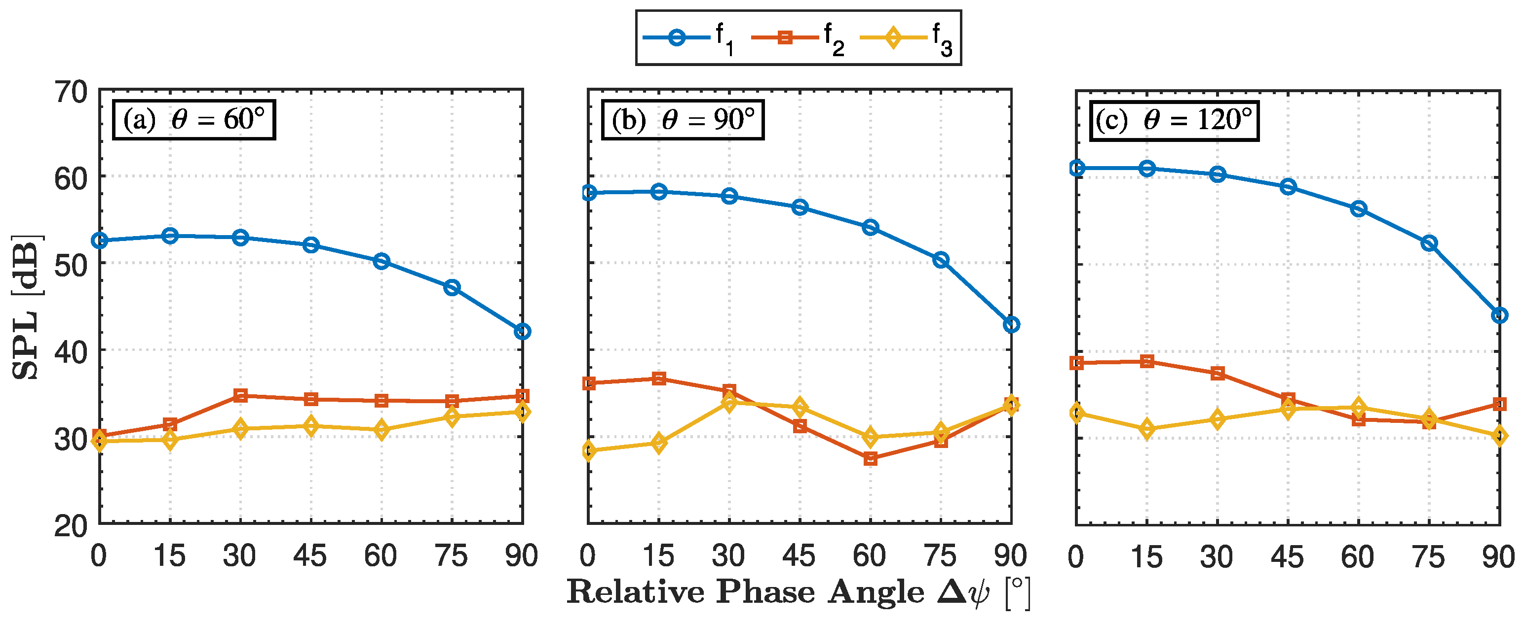
Figure 7, together with
Table 3, compares the noise levels at the first (
Hz), second (
Hz), and third (
Hz) blade-passing frequencies (BPFs) as a function of the relative phase angle
for two-bladed propellers (
) at observer positions
,
, and
.
The BPF is calculated using the following equation:
where RPM is the rotational speed and
is the number of blades. Irrespective of the observer angle, the noise level at the first BPF (
) decreases with increasing relative phase angle
. The tonal component is most pronounced at a relative phase angle
, where the two propellers operate in phases, resulting in constructive interference of their pressure fields. The noise level remains approximately constant up to a relative phase angle
, beyond which it progressively decreases, reaching a minimum at a relative phase angle
due to destructive interference. At an observer angle
, the noise level at the first blade-passing frequency (
) ranges from a maximum of
at a relative phase angle
to a minimum of
at a relative phase angle
, resulting in a noise reduction of
, as shown in
Table 3. This range increases to
at an observer angle
and further to
at an observer angle
, with the highest noise level consistently observed at a relative phase angle
and the lowest at a relative phase angle
(see
Table 3).
The second BPF (
) and the third harmonic (
) exhibit trends that differ significantly from those of the first BPF across all observer angles and relative phase angles. At an observer angle of
, the minimum noise level at the second BPF (
) occurs at a relative phase angle of
, while the maximum noise level is observed over a relatively constant range between
, resulting in a noise reduction of
. For observer angles of
and
, the maximum noise level occurs at relative phase angle
, and the minimum at relative phase angle
. Substantial noise reductions are still observed with varying relative phase angles: at observer angle
, the reduction is approximately
, and at observer angle
, it is around
. These variations are also attributed to unsteady loading interactions, in accordance with propeller noise theory [
44]. The third harmonic,
, exhibits the lowest noise reduction achieved through phase synchronisation, with a maximum reduction of
. For observer angles
and
, the noise reduction
remains below approximately
, while at observer angle
, it is around
. The maximum and minimum noise levels occur at different relative phase angles for
–
and
, as shown in
Table 3.
Figure 8 illustrates the variation of overall sound pressure level (OASPL) with respect to the relative phase angle (
) for observer positions at
,
, and
. To compute the overall sound pressure level (OASPL), the integration is performed over the frequency range from
to
, using the following equation to evaluate the contribution of the first three blade-passing frequencies (BPFs) to the total sound level:
In general, a noticeable reduction in OASPL is observed as the relative phase angle () increases, consistently across all observer angles. This trend becomes particularly significant beyond , where destructive interference between the acoustic sources becomes more dominant. At , the OASPL decreases from approximately 55.5 dB at to around 47.5 dB at , marking a reduction of about 8 dB. Similarly, for , the OASPL drops from nearly 55.8 dB to 47.8 dB, while at , it decreases from about 55 dB to 46.5 dB, showing the greatest reduction of approximately 8.5 dB. These results show that the combined noise level of the first three blade-passing frequencies (BPFs) exhibits a reduction of approximately 8 dB as the relative phase angle increases, highlighting the effectiveness of phase synchronization in mitigating tonal noise components.
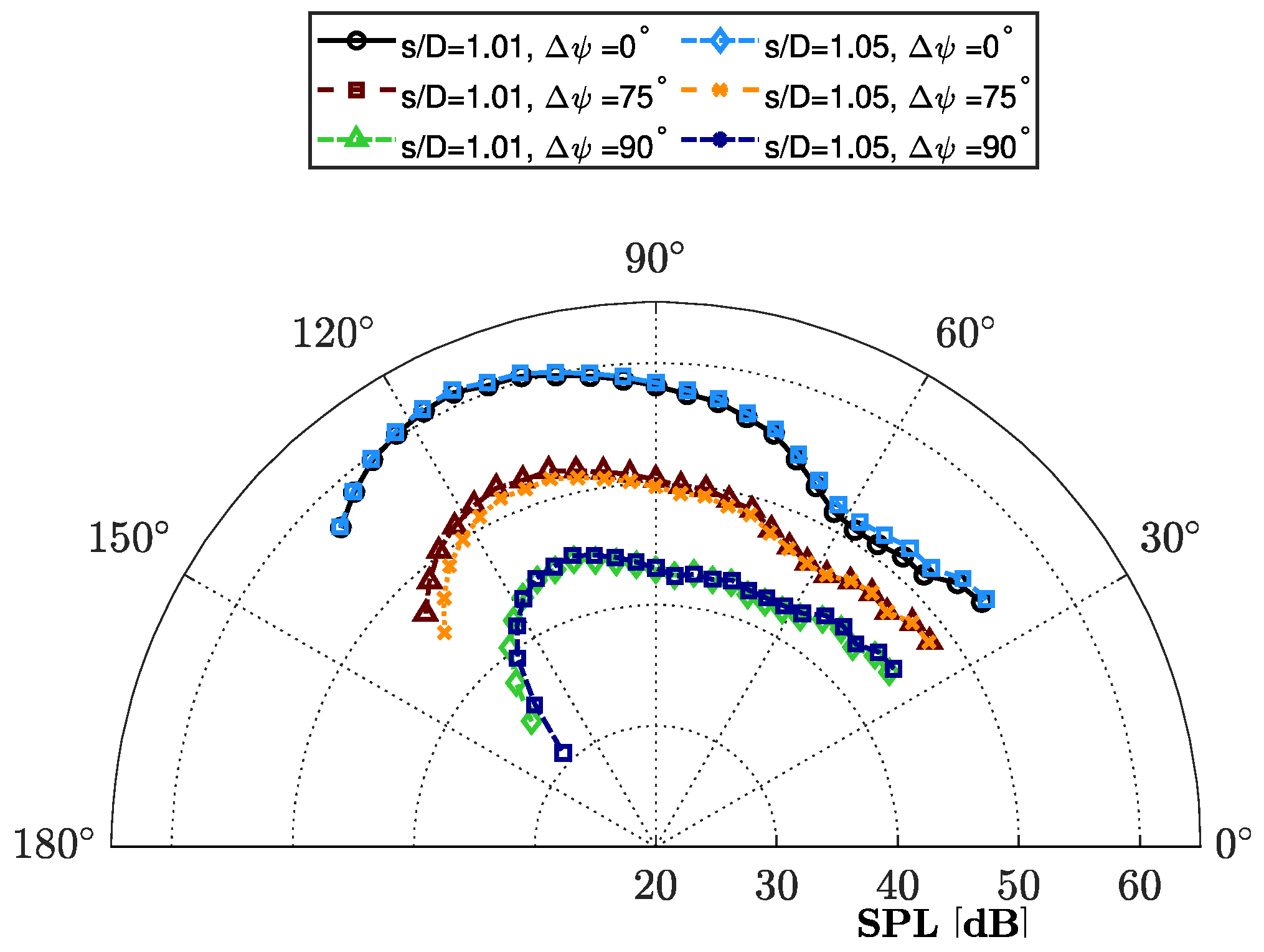
Figure 9 presents the directivity patterns of sound pressure levels (SPLs) at the first BPF for two-bladed propellers at a center-to-center spacing of
, considering two different
ratios and seven distinct relative phase angles. In general, the directivity of the BPF tone exhibits noticeable amplification toward the downstream direction. However, the most significant changes are observed when comparing the directivity at
and
. Comparison across relative phase angles (
) shows that configurations with
yield little noise reduction compared to the reference case (
). For
, SPL decreases progressively, with the most noticeable reductions at downstream angles (
). The greater attenuation at downstream observer angles for the fully out-of-sync case (
) results in a more “downstream-tilted” pattern. For both configurations, the maximum noise level is recorded at
. As the relative phase angle increases, a reduction in SPL is observed for both propeller configurations due to destructive interference between the noise waves radiated by each propeller, with the minimum noise level achieved at
. For the configuration with
(
Figure 9a), the noise reduction ranges from 12 to 18 dB between
and
, depending on the directivity angle. This relatively narrow range indicates a fairly consistent level of noise reduction across the directivity pattern. In contrast, for the configuration with
(
Figure 9b), the noise reduction ranges from 8 to 22 dB. This wider range suggests that a larger pitch-to-diameter ratio results in more significant variations in noise reduction, potentially due to changes in the aerodynamic loading between the blades [
11]. The directivity pattern varies for different
ratios, as explained in the literature [
11]. However, the overall shape does not appear to be significantly influenced by changes in the relative phase angle. This observation suggests that while the
ratio is a critical factor in determining the noise field’s structure, alterations in the relative phase angle mainly affect the amplitude rather than the directional characteristics of the noise.
Other studies have highlighted variations in noise directivity. For instance, when the propellers are in phase (
), the resulting directivity pattern resembles that of a monopole source. Conversely, a rotor phase difference of
produces a dipole-shaped directivity pattern [
17,
19]. Another study investigated dual-motor configurations using phase synchronization and found that, at
, the noise directivity was nearly axisymmetric and circular in the in-plane view. As the elevation angle increased, configurations with
and
developed a figure-eight pattern, while
resulted in a more irregular shape [
42]. A recent numerical study also showed that closely spaced rotors can generate acoustic fields similar to dipole and quadrupole sources, effectively capturing directivity features observed in experiments [
45]. These previous studies, along with the present results, suggest that the shape of the directivity pattern depends strongly on the configuration and flow conditions.
Figure 10 presents a comparative analysis of sound quality metrics (SQMs) for two two-bladed, 9-inch-diameter propellers with different pitch-to-diameter ratios (
and
), operating at a constant advance ratio of
and 5000 RPM. Each plot shows how sound quality metrics, specifically loudness and psychoacoustic annoyance, vary with the directivity angle
, and includes three relative phase angles (0°, 75°, and 90°) to examine the influence of phase offset on perceived noise. Generally, the relative phase angle
results in the highest loudness (see
Figure 10a,b). As a consequence, the psychoacoustic annoyance is also the highest (see
Figure 10c,d), and it decreases with increasing relative phase angle across all directivity angles and for both pitch-to-diameter ratios. For the lower pitch-to-diameter configuration (
), the loudness remains relatively lower than in the higher pitch-to-diameter configuration (
). In the case of the higher pitch-to-diameter ratio, loudness increases sharply with directivity angle, peaking beyond 11 sones near the observer angle
. This is likely due to the elevated loading and associated noise levels for the
configuration, as illustrated in
Figure 9. These results underscore the importance of considering both geometric and operational parameters when evaluating propeller noise under forward flight conditions, as lower pitch-to-diameter propellers (
) are less sensitive to phasing compared to higher pitch-to-diameter configurations (
).
To assess whether the separation distance significantly affects noise reduction via phase synchronization,
Figure 11 presents the SPL directivity at the first BPF for two-bladed propellers using two center-to-center separation distances,
and
. To better visualize the effect of separation distance, the results are shown for three different relative phase angles:
,
, and
. Regardless of the separation distance, the shape of the directivity remains unchanged, indicating similar acoustic behavior for
at each respective relative phase angle. The noise reduction observed is nearly the same for the relative phase angles of
,
, and
, with minor fluctuations of less than 1 dB. Specifically, there is an approximate 1 dB disparity in the upstream region between these two separation distances, after which the magnitudes converge and remain consistent regardless of separation distance. This indicates that the overall noise reduction, in terms of the first BPF noise level, remains unchanged when using different center-to-center distances with phase synchronization.
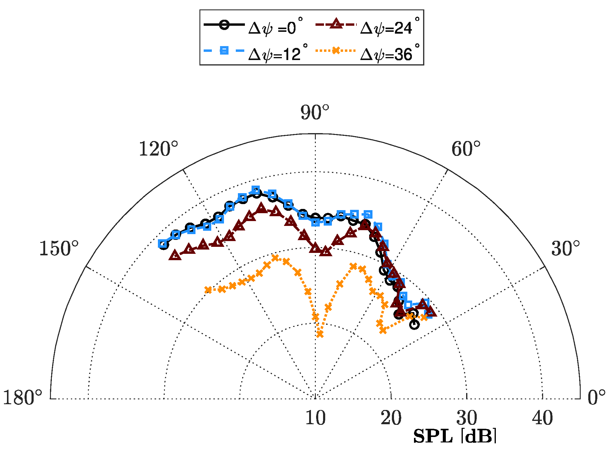
Results for the Five-Bladed Propeller Configuration
Figure 12 illustrates the directivity pattern of the sound pressure level (in dB) at the first blade passing frequency (BPF) for five-bladed propellers at an advance ratio of
. The propellers operate at a constant rotational speed of 4000 RPM with a center-to-center distance of
. To explore the impact of phase synchronization, we analyze four different relative phase angles:
,
,
, and
. In general, the five-bladed configuration also demonstrates significant noise reduction when the propellers operate in phase synchronization. Specifically, noise reduction becomes apparent at a relative phase of
, especially beyond an observer angle of
. The maximum noise reduction occurs at a relative phase of
, where a reduction of around 15 dB is observed at an observer angle of
. At this angle, destructive interference is at its peak, significantly reducing the sound pressure level. In the upstream region, the noise reduction is moderate, ranging from 2 to 5 dB, while in the downstream region, the reduction is more substantial, ranging from 8 to 10 dB.
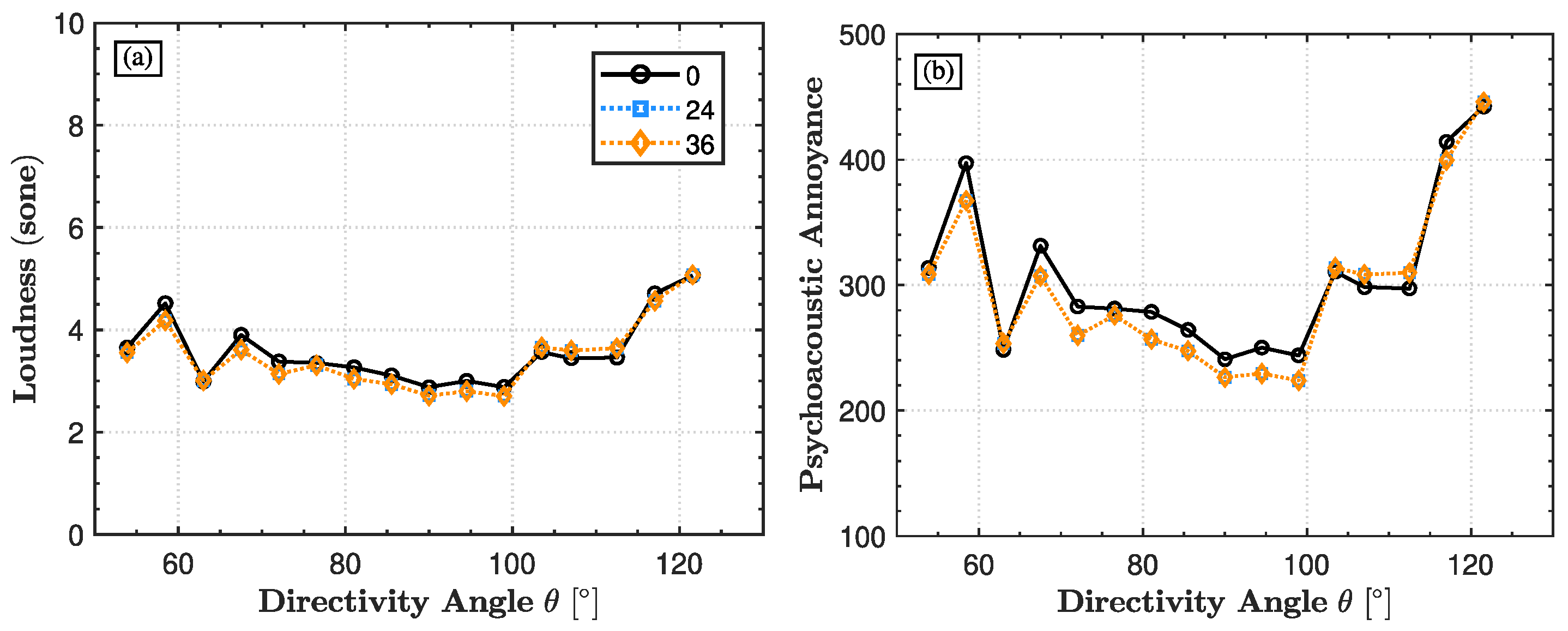
Figure 13 illustrates the directivity patterns of loudness and psychoacoustic annoyance at the first BPF for five-bladed propellers operating at an advance ratio of
, a rotational speed of 4000 RPM, and a center-to-center spacing of
. The results are presented for three relative phase angles: 0°, 24°, and 36°. Across all directivity angles, the loudness remains relatively consistent across the different phase angles, with only a slight variation observed between
and
(see
Figure 13a). The psychoacoustic annoyance plots (
Figure 13b) exhibit a similar trend, with the relative phase angle
producing the highest annoyance at most directivity angles. As the phase offset increases to between 24° and 36°, the annoyance levels decrease slightly.


