1. Introduction
Unmanned aerial vehicles (UAVs) are efficient and intelligently tasked as aircraft operated through remote control or pre-stored programs. Initially, UAVs were developed in 1944 as remotely controlled bomb carriers equipped with cameras for the US military [
1]. Their high flexibility and maneuverability have made this technology widely used in power inspection, surveillance, animal and plant protection, and material delivery. The total market sales of unmanned aerial vehicles are projected to hit 43 billion US dollars by 2025, with a compound annual growth rate of 13.8% [
2].
As a power-consuming device, UAVs’ endurance and flight distance are limited by battery capacity. Currently, there are three traditional charging methods for UAVs: the first is to use solar energy batteries to collect and store energy during flight, such as China’s “Rainbow Solar UAV” [
3], but this method is only suitable for UAVs with large wings. The second method is to replace the battery through a mechanical arm, which is efficient in operation but requires high-precision equipment and is costly [
4]. The third method uses metal electrodes for contact charging, which is efficient and low-cost but has issues with exposed metal electrodes wearing out and short-circuit risks, posing safety concerns [
5]. Wireless Power Transmission (WPT) technology can power multiple devices simultaneously, significantly saving time and reducing the burden on operators. Since current battery technology is directly proportional to battery capacity and weight, increasing battery storage to extend endurance would limit the UAV’s flexibility and convenience. Therefore, flexible and reliable energy replenishment is crucial for UAVs to achieve long-term operation, which is an urgent UAV development and application issue.
WPT is a technology that directly transmits energy without an electrical connection between the output and input terminals [
6]. WPT technology significantly reduces the risks of circuit sparks, short circuits, equipment corrosion, and ageing in the energy transmission process, and enhances the flexibility of energy supply [
7,
8]. WPT technology has become an effective solution for energy supply to drones in wilderness and harsh environments [
9]. Currently, there are two primary methods of WPT technology for UAVs: magnetic coupled and capacitive WPT, and a novel capacitive power transfer system for UAVs with lightweight receivers was proposed in Ref. [
10]. Refs. [
11,
12,
13,
14] illustrates a magnetically coupled UAV WPT system with multiple structures.
The magnetic coupler serves as the core component of UAV WPT systems, with its design directly affecting energy transfer efficiency and system anti-misalignment capability. Traditional magnetic coupling mechanisms predominantly adopt planar coil structures. For instance, the orthogonal bipolar magnetic coupling device utilizes a DD-shaped air-core coil at the transmitter and a vertically placed air-core coil at the receiver to achieve energy transfer. While this configuration offers high transmission power and low magnetic flux leakage interference, it restricts UAV landing angles and fails to enable omnidirectional energy transfer [
11]. A magnetic coupling device based on a spatial rotating magnetic field was introduced in [
12]. By employing three coplanar regular hexagonal transmitting coils and controlling the phase difference of excitation currents, this design generates a spatial rotating magnetic field, enabling effective coupling between the receiving coil and transmitting coils at arbitrary positions and angles. This significantly enhances omnidirectional energy transfer performance. Additionally, Cai, C. et al., in [
13], proposed a dual-orthogonal DD-dual combined solenoid magnetic coupling mechanism. Through a dual-transmitter–dual-receiver structural design, this approach optimizes magnetic field distribution, reduces flux leakage, and effectively mitigates cross-coupling issues between same-side coils, thereby improving system anti-misalignment performance. Wang, H. et al., in [
14], proposed a transmitting coil consisting of eight solenoid coils, which expands the wireless charging area and reduces output fluctuations. Furthermore, a transmission coil structure based on multi-ring sector coils has been proposed, which significantly improves the misalignment tolerance of UAV WPT systems [
15] but has weak coverage for group UAVs.
Based on the aforementioned coupler structure of the UAV WPT system, it is evident that the structure of the transmitting coil exerts a substantial influence on the performance of the UAV WPT system. The Refs. [
16,
17,
18] further elaborate that the variation of mutual inductance between the transmitting and receiving coils of the coupler will cause significant changes in the system’s performance. Additionally, the references regarding the design of the coupler for the WPT system primarily focus on designing coupler dimensions that meet the system’s mutual inductance requirements. Therefore, optimizing the mutual inductance design of the coupler is particularly important for enhancing the performance of the WPT system. The excellent size of the transmitting coil contributes to the improvement of energy and efficiency in UAV WPT systems. However, the design of coil structures often requires establishing a three-dimensional model, finite element analysis using electromagnetic simulation software, and ultimately obtaining a suitable coil structure [
19]. This approach is both time-consuming and labor-intensive.
Meanwhile, the regular hexagonal transmitting coils exhibit notable advantages. However, the hexagonal array transmitting coils’ size design significantly impacts the coupler mutual inductance. Compared with DD and planar circular coils, the construction of the 3D structure of the regular hexagonal array-type coil requires more physical and mental energy, and the parametric scanning using the joint modeling of SolidWorks and COMSOL takes more time. Determining how to optimize the dimensions of hexagonal and receiving coils to maximize mutual inductance remains a key challenge for achieving high-efficiency UAV wireless power transfer. Therefore, exploring a rapid design approach for array coils is essential. This paper examines it by using COMSOL 6.2, Ansys 2025, and SolidWorks 2022.
In recent years, alongside the advancement of deep learning technology, the integration of AI and WPT technology has become increasingly close [
20]. A machine learning strategy based on neural networks has been researched for real-time range-adaptive automatic impedance matching in WPT systems. This approach effectively forecasts the optimal parameters of the adjustable matching network and chooses range-adaptive transmitting coils [
21]. A real-time adaptive impedance matching method is based on a single iteration, which calculates the optimal impedance matching network parameters by estimating the amplitude and phase of the input impedance, thereby improving the efficiency of wireless power transmission [
22]. Furthermore, a method utilizing convolutional neural networks to train and predict the performance of coupled coils has been proposed to optimize key parameters of WPT systems [
23]. In summary, the application of artificial intelligence deep learning technology in the field of WPT is becoming increasingly deep, and it has improved the accuracy of wireless energy transmission system control and the efficiency of coupler design. Therefore, this paper proposes to combine deep neural networks with the design of array couplers for UAV WPT systems and explore the size design method of array couplers. Through the method presented in this paper, the goal is to enhance the design efficiency of the coupler in the UAV array-type WPT system and advance the application of UAVs in various fields.
Therefore, the primary contributions of this paper are as follows:
Studied the impact of the length of the receiving coil and the change in the aperture of the transmitting coil on the mutual inductance of the coupler, and obtained the constraint relationship between the length of the receiving coil and the outer radius of the array-type transmitting coil.
Based on the deep learning method, a deep neural network model consisting of three parameter input layers ( the radius of a single regular hexagonal circumscribed circle of array-type transmitting coil , the circumscribed circle radius of a single regular hexagonal coil hole , and receiving coil length ), four layers of fully linked hidden layers, and the output layer (mutual inductance M) is constructed, and a design method of an array regular hexagonal coupler is proposed based on the above deep neural network model.
To verify the adaptability and accuracy of the deep neural network model, a measurement platform for the mutual inductance of the array-type coupler in a UAV WPT system was built. The measured value of the coupler’s mutual inductance was 4.23 μH, which is close to the generated value of 4.31 μH from the trained model, verifying the proposed method.
The remainder of this paper is structured as follows.
Section 2 analyzes the variation law of the mutual inductance of the array-type coupler in a UAV WPT system and studies the impact of the length of the receiving coil and the change in the aperture of the transmitting coil on the coupler’s mutual inductance.
Section 3 proposes a design method for couplers based on deep neural networks, using deep learning techniques to improve the design efficiency of array-type couplers corresponding to multiple types of UAVs. The experimental results are presented in
Section 4.
Section 5 provides a summary of the conclusions drawn from this research.
2. Mutual Inductance Analysis of Array-Type Coupler in UAV WPT System
2.1. Introduction to Array-Type Coupler
In the current operational scenarios of UAV swarms for cluster-oriented tasks, the efficient fulfillment of charging demands has become a critical focus. During mission execution by UAV swarms, frequent charging procedures directly impact operational efficiency. In this context, the array-type transmitting structure demonstrates significant advantages. Through carefully designed arrangements of multiple transmitting units, this configuration effectively enhances the charging efficiency of the UAV. When undergoing charging, UAVs may experience positioning deviations due to airflow disturbances during flight or minor errors in positioning systems. The array-type transmitting structure compensates for these adverse effects through its unique layout. Multiple transmitting units can complementarily establish charging connections with the UAV, mitigating efficiency degradation caused by positioning deviations. Meanwhile, in Ref. [
12], a free-positioning inductive power transfer (IPT) system was proposed to achieve reliable power transfer under large-range horizontal misalignment and arbitrary 2-D rotation. A reconfigurable circuit topology was designed and modeled, enabling the array-type coils to be flexibly activated based on the UAV’s landing position. This ensures a stable power supply for UAV swarms during cluster missions, laying a solid foundation for efficient task completion.
As illustrated in
Figure 1, the array type of UAV WPT system employs three coplanar regular hexagonal coils in a spatial arrangement.
These coils are symmetrically distributed with adjacent pairs, positioned above triangularly assembled ferrite blocks as illustrated in
Figure 2. Since the current phases of each coil differ by 120°, the magnetic field direction generated by each coil changes over time. This dynamic variation enables more uniform spatial distribution of the composite magnetic field, reduces magnetic dead zones, and improves the coverage of energy transmission.
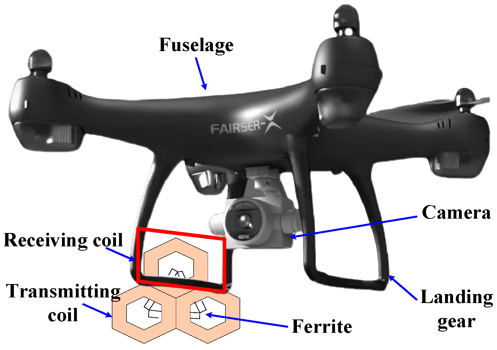
The receiving coil is fixed on the UAV landing gear, with its size constrained by the landing gear’s width. It is arranged perpendicular to the plane of the transmitting coil to capture the electromagnetic field generated by the transmitting coil in space, enabling wireless energy transfer. Since the UAV lands directly on the transmitting coil surface, the transmission distance between the transmitting and receiving coils corresponds to the thickness of the landing gear.
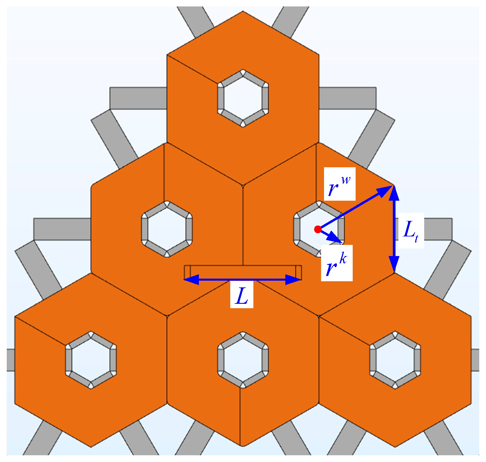
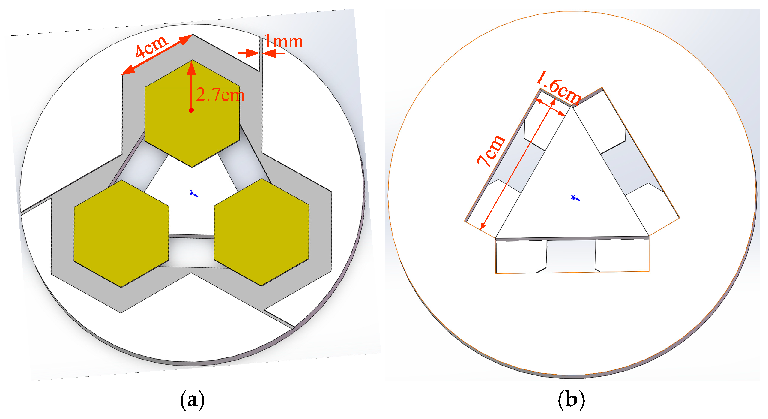
The mutual inductance variation in wireless power transfer system couplers is often influenced by the transmitting/receiving coils’ dimensional structure and transmission distance. For the array-type WPT system coupler, as the transmission distance between transceiver coils remains constant, the dimensional structure of the coils becomes the primary factor affecting mutual inductance changes. The dimensional structure model for the array-type WPT system illustrated in
Figure 3 is established as illustrated in
Figure 1.
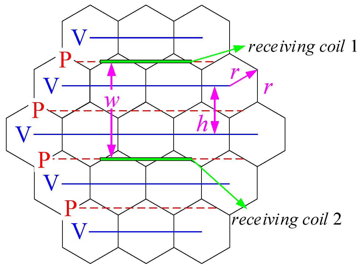
Among these, the radius of a single regular hexagonal circumscribed circle of array-type transmitting coil is defined as
, the edge length of the regular hexagon as
, and the distance between a pair of UAV landing gear as
. Based on analysis from [
12], the spatial magnetic field generated by the array-type coils exhibits peaks and valleys. Let the distance between the nearest pair of magnetic field peaks in an array-type transmitting coil (
) be
, then
. Additionally, considering the fabrication size requirements of the array-type coils, this paper assumes
. Consequently,
. The flexible activation of drone landing positions can be achieved using the method described in Reference [
12].
2.2. Effect of Receiving Coil Tilt Angle on Coupler Mutual Inductance
For the array-type coupler illustrated in
Figure 2, the mutual inductance value at the central position or in an offset state should be as favorable as possible in practical applications. In general, the mutual inductance of the coupler diminishes as the offset distance increases. Therefore, this paper aims to maximize the mutual inductance value at the optimal position. The mutual inductance value of the array coupler studied in this paper is defined as the sum of the magnetic fluxes passing through the receiving coils when a symmetric three-phase current is supplied to the three transmitting coils in a single array.
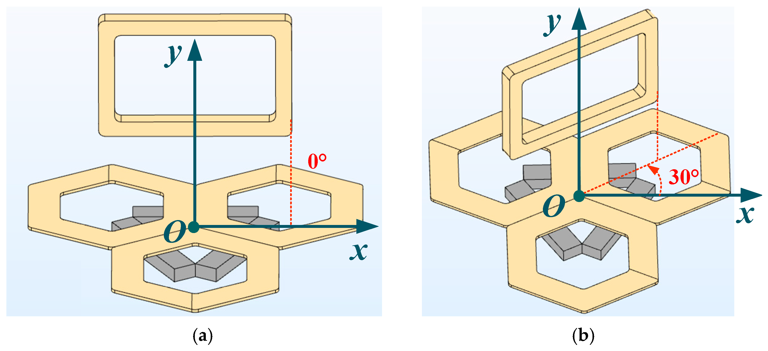
In this paper, when the center of the receiving coil coincides with the center of the three transmitting coils, the change of mutual inductance value of the receiving coil when it rotates around the central axis of the transmitting coil is analyzed. Firstly, the array coupler illustrated in
Figure 4 is constructed in the finite element electromagnetic simulation software COMSOL, and the
xO
y coordinate system is established. When the receiving coil is parallel to the center line of the two coils in the transmitting coil array, it is defined as a position with a deflection angle of 0°, as illustrated in
Figure 4a. When the landing gear rotates 30° counterclockwise around the central axis, the position relationship of the transceiver coil is illustrated in
Figure 4b.
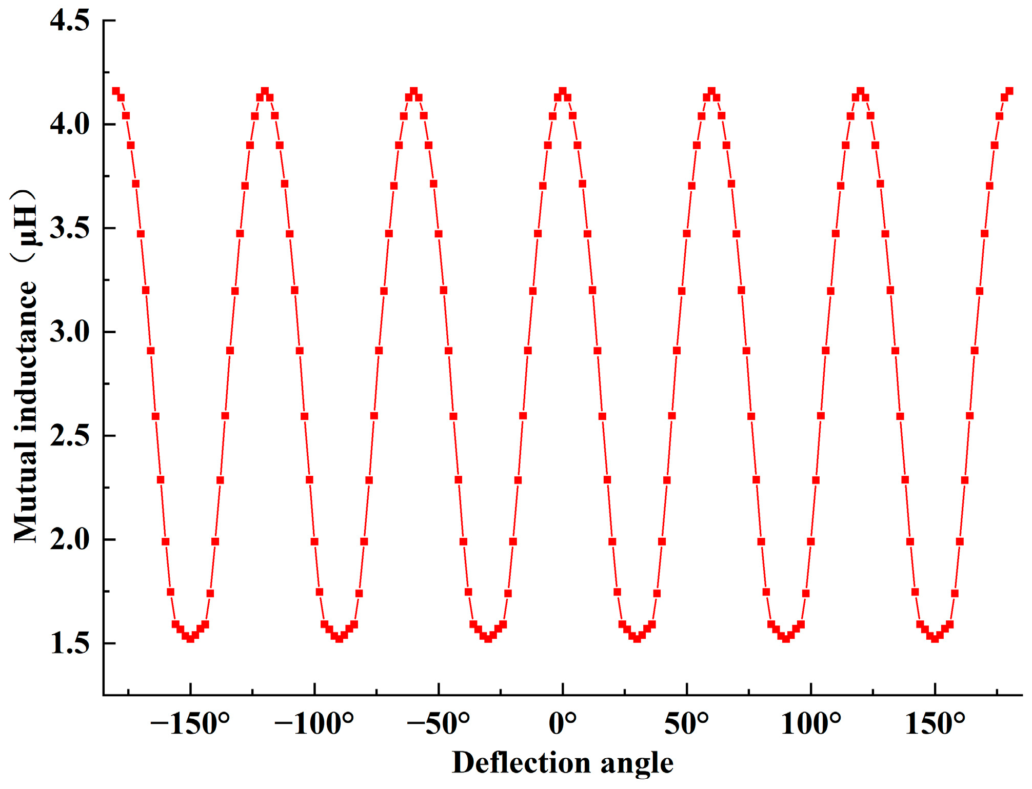
In order to analyze the variation law of coupler mutual inductance of the array-type UAV WPT system, the width of the receiving coil is first assumed to be 80 mm, the circumscribed circle radius of a single regular hexagonal coil hole(aperture)
is 18.5 mm, and the number of turns is 10. The radius of the circumscribed circle of the launch coil is 60 mm, and the number of turns is 10. The ferrite core is made of PC95 material and has a size of 78 mm × 15 mm × 9 mm. Therefore, when the receiving coil rotates around the center of the array-type transmitting coil by 360°, the variation pattern of the coupler’s mutual inductance is illustrated in
Figure 5.
From the variation curve pattern, it can be observed that the coupler’s mutual inductance exhibits periodic fluctuations with the receiving coil’s angular displacement. The mutual inductance reaches maximum values when the receiving coil is positioned at 0°, ±60°, or ±120°. The mutual inductance demonstrates minimal fluctuation within a deflection angle range of ±15°. To systematically analyze the influence of dimensional variations in the receiving and transmitting coils on mutual inductance, the 0° configuration will serve as the reference baseline for subsequent investigations.
2.3. The Effect Pattern of Receiving Coil Dimensions on the Coupler Mutual Inductance
This section establishes a modular coupler structure, illustrated in
Figure 6, constrained by the width of the UAV landing gear and the dimensions of the transmitting coil.
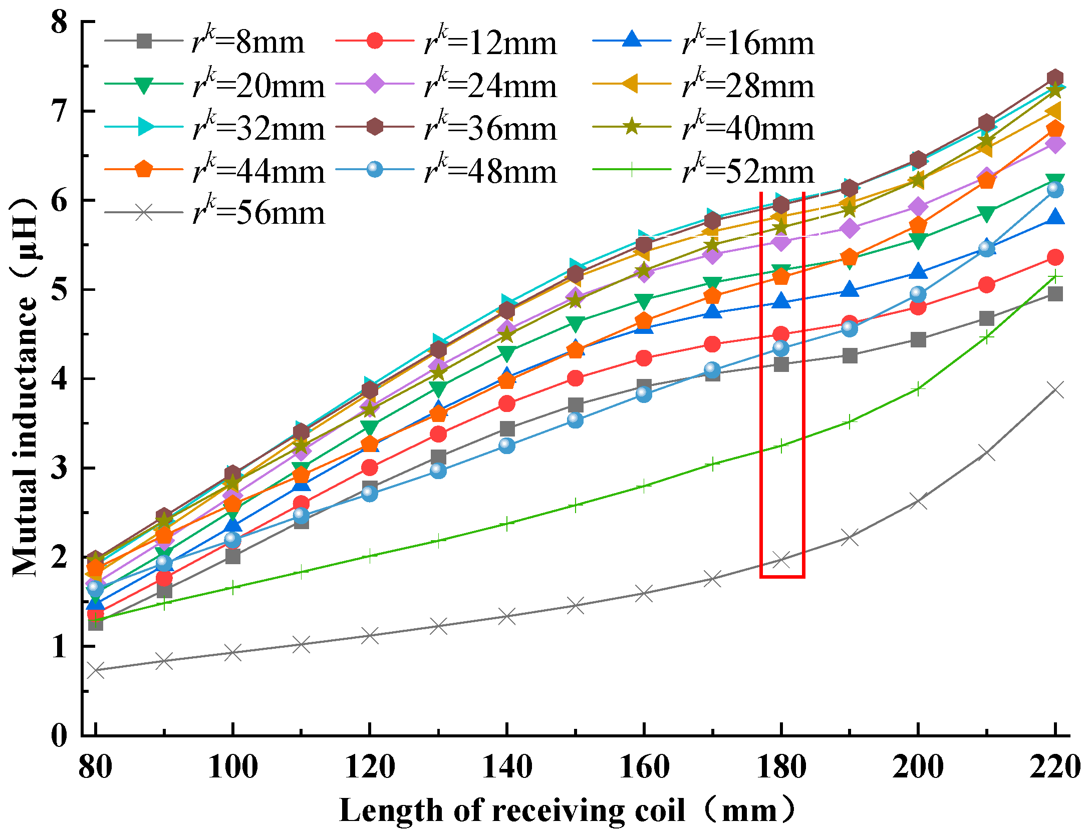
To analyze the mutual inductance variation with receiving coil length, the radius of the circumscribed circle of a single transmitting coil
is 60 mm, with its circumscribed circle radius of a single regular hexagonal coil hole(aperture)
set to 8 mm. The ferrite core is made of PC95 material and has a size of 78 mm × 15 mm × 9 mm. As the receiving coil length
varies from 80 mm to 220 mm, finite element electromagnetic simulations yield the mutual inductance trend illustrated in
Figure 7.
The mutual inductance of the coupler exhibits a linear growth trend as the receiving coil length increases below 180 mm. However, when the length of the receiving coil is around 180 mm, the growth rate of the coupler’s mutual inductance is almost 0. In this case, is a platform with increased mutual inductance. When is greater than 180 mm, the receiving coil will span the three-coil array, which will further increase with the mutual inductance, but the transmitter coil control in practical applications will be more complex.
In order to further the range of extreme values of the receiving coil, a structural diagram for coupler dimension analysis is established as illustrated in
Figure 8. From the diagram, it can be observed that as the length of the receiving coil increases, it first intersects with the waistline of the array-type transmitting coil, at which point the length
. Further increase will result in an intersection with the envelope of the array-type coil, at which point the length
.
By summing
and
and taking their average, we obtain the critical length of the receiving coil:
When is 60 mm, is 181.66 mm, which approximates the 180 mm obtained from electromagnetic simulation calculations. Therefore, the maximum value of the receiving coil length should not exceed , and the width of the UAV landing gear must also be considered in the design. In order to further improve the charging performance of the UAV, considering the load of the UAV, when designing the array-type coupler, the length of the receiving coil should be determined according to the width and height of the landing gear, and then the radius of the circumscribed circle of a single transmitting coil should be calculated using Equation (1) to maximize the design of mutual inductance.
2.4. The Law of the Aperture of the Transmitting Coil on the Mutual Inductance of the Coupler
Firstly, suppose the distance between a pair of UAV landing gear is . Based on the aforementioned analysis, the length of a single regular hexagonal side of an array emitting coil is 60 mm. Now, by varying the aperture of the transmitting coil and the length of the receiving coil, the variation law of the coupler can be studied.
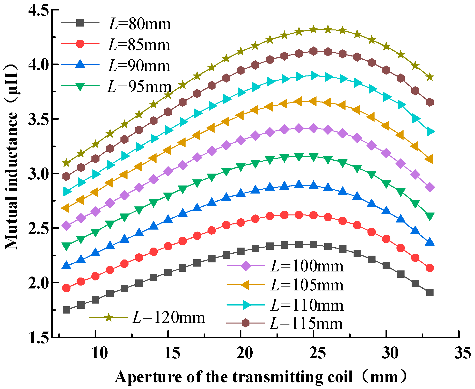
When the aperture range of the transmitting coil is 8 mm to 56 mm, the length of the receiving coil is 110 mm to 180 mm, and the width of the receiving coil is 80 mm, the variation law of the coupler’s mutual inductance can be illustrated in
Figure 9. The shape of the receiving coil is rectangular.
From the figure, it is evident that when the size of the receiving coil remains constant, with the increase in the aperture, the coupling of the coupler increases initially and then declines. The maximum coupling value appears at an aperture of approximately 33 mm; at this point, the length of the receiving coil is 180 mm. That is, the coupling of the array-type coupler is affected by the size of the transmitting coil, the aperture, and the receiving coil, and there is an optimal value. Based on this, this paper analyzes another landing gear width.
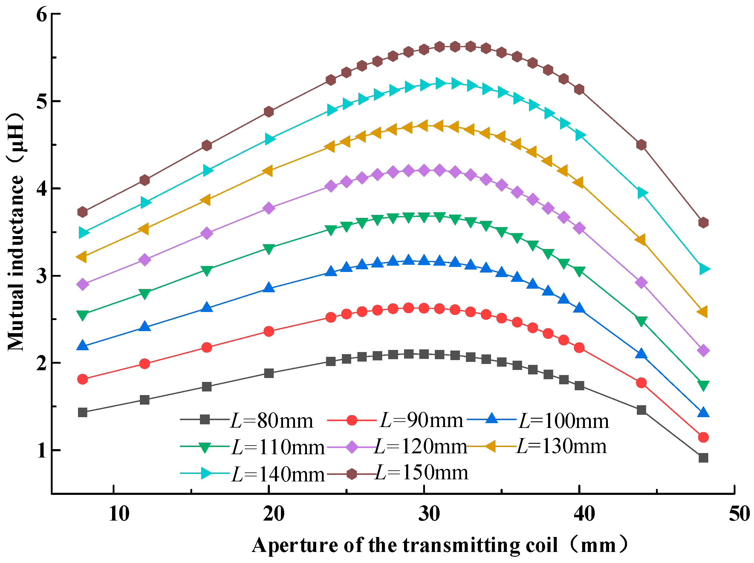
Assume that the width of a pair of landing gears for another model of UAV is . According to the aforementioned analysis, the outer edge length of the transmitting coil . At this point, the variation law of the coupler is studied by changing the aperture of the transmitting coil and the length of the receiving coil.
When the aperture range of the transmitting coil is 8 mm to 48 mm and the length of the receiving coil is 80 mm to 150 mm, the variation law of the coupler’s coupling can be obtained as illustrated in
Figure 10.
From the figure, it is evident that when the size of the receiving coil remains unchanged, with the increase in the hole diameter, the coupling between the couplers first increases and then decreases. The maximum coupling occurs at a hole diameter of approximately 31 mm. At this time, the length of the receiving coil is 150 mm.
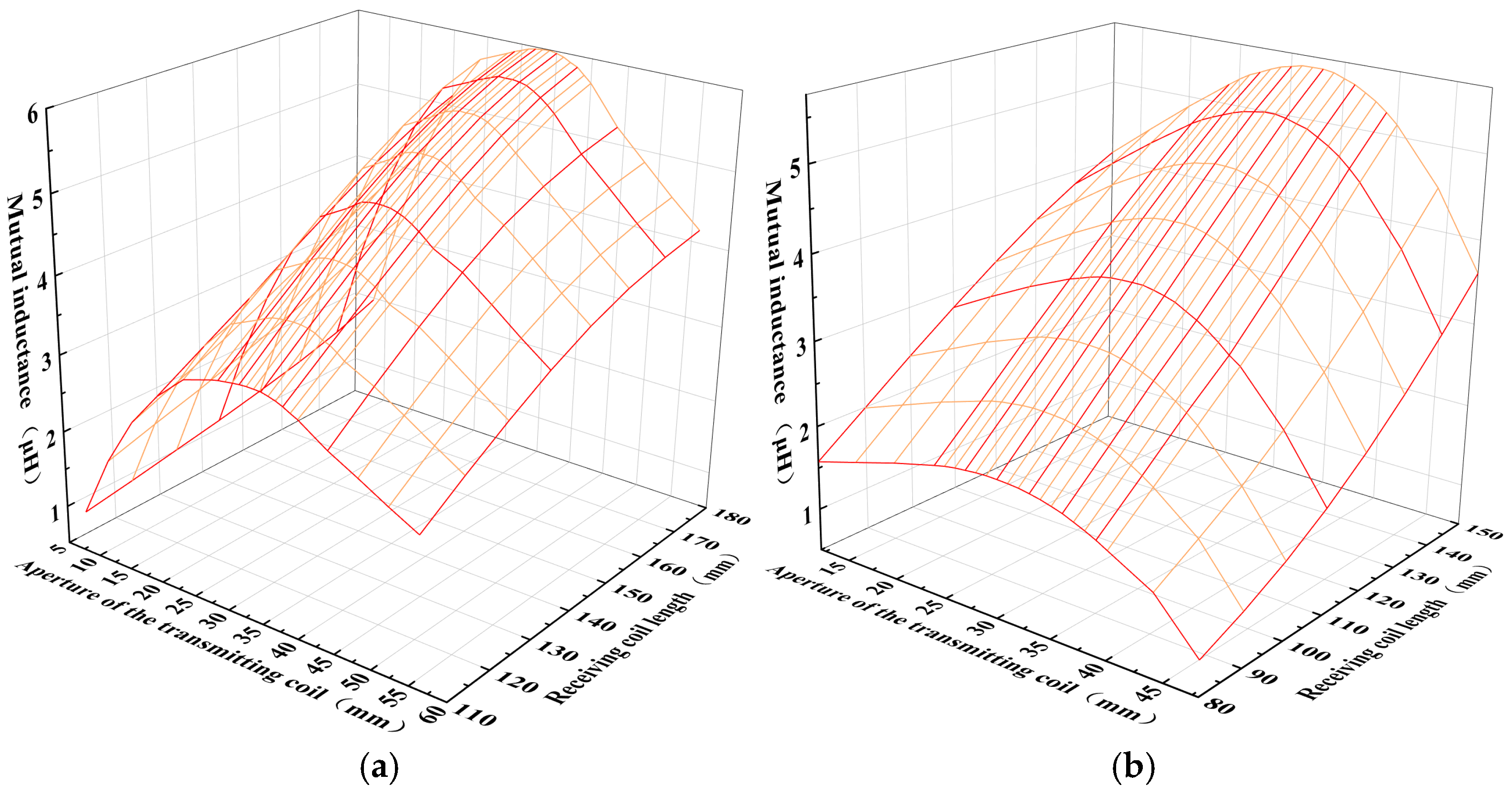
Further, this paper presents a 3D surface plot shown in
Figure 11. It can be observed from the graph that increasing the length of the receiving coil significantly enhances the mutual inductance of the array coupler. When the length of the receiving coil remains constant, the mutual inductance first increases and then decreases with an increase in the aperture size. It can also be noted from the graph that the variation in the mutual inductance of the coupler is quite sensitive to changes in the length of the receiving coil. The length of the receiving coil determines the upper and lower limits of the mutual inductance, while variations in aperture affect the optimal value of the mutual inductance for the array-type coupler.
The above analysis shows that when designing the coupler for an array-type WPT system, the width and length of the landing gear should be comprehensively considered, and the sizes of the receiving and transmitting coils should be designed accordingly. Then, electromagnetic simulation software can perform finite element calculations and solutions.
However, this method requires first establishing a 3D model and then using electromagnetic simulation software for finite element solution calculations, which is time-consuming and has low calculation efficiency. This paper proposes adopting a method combining artificial intelligence technology with electromagnetic simulation for the design of array-type couplers in a WPT system.
3. Design of the Coupler Based on Deep Neural Networks
In recent years, alongside the advancement of artificial intelligence technology, deep learning technology has rapidly advanced in both academic and industrial sectors. It has achieved significant success in many traditional recognition tasks, such as image, speech, and text recognition, demonstrating its ability to handle complex recognition tasks. This has attracted numerous experts and scholars to study its theories and applications. Neural networks are the core of deep learning technology. They are constructed by simulating the neural networks of the human brain. Typically, a neural network consists of an input layer, hidden layers (intermediate layers), and an output layer, each functioning as a distinct part. The input layer is usually used to receive external input data, the hidden layers primarily process and transform the data, and the output layer outputs model fitting results. A deep neural network is a neural network with additional hidden layers. Through verification, it has been found that adding more hidden layers enhances the network’s learning and fitting capabilities. Generally, neural networks with three or more hidden layers are called deep neural networks.
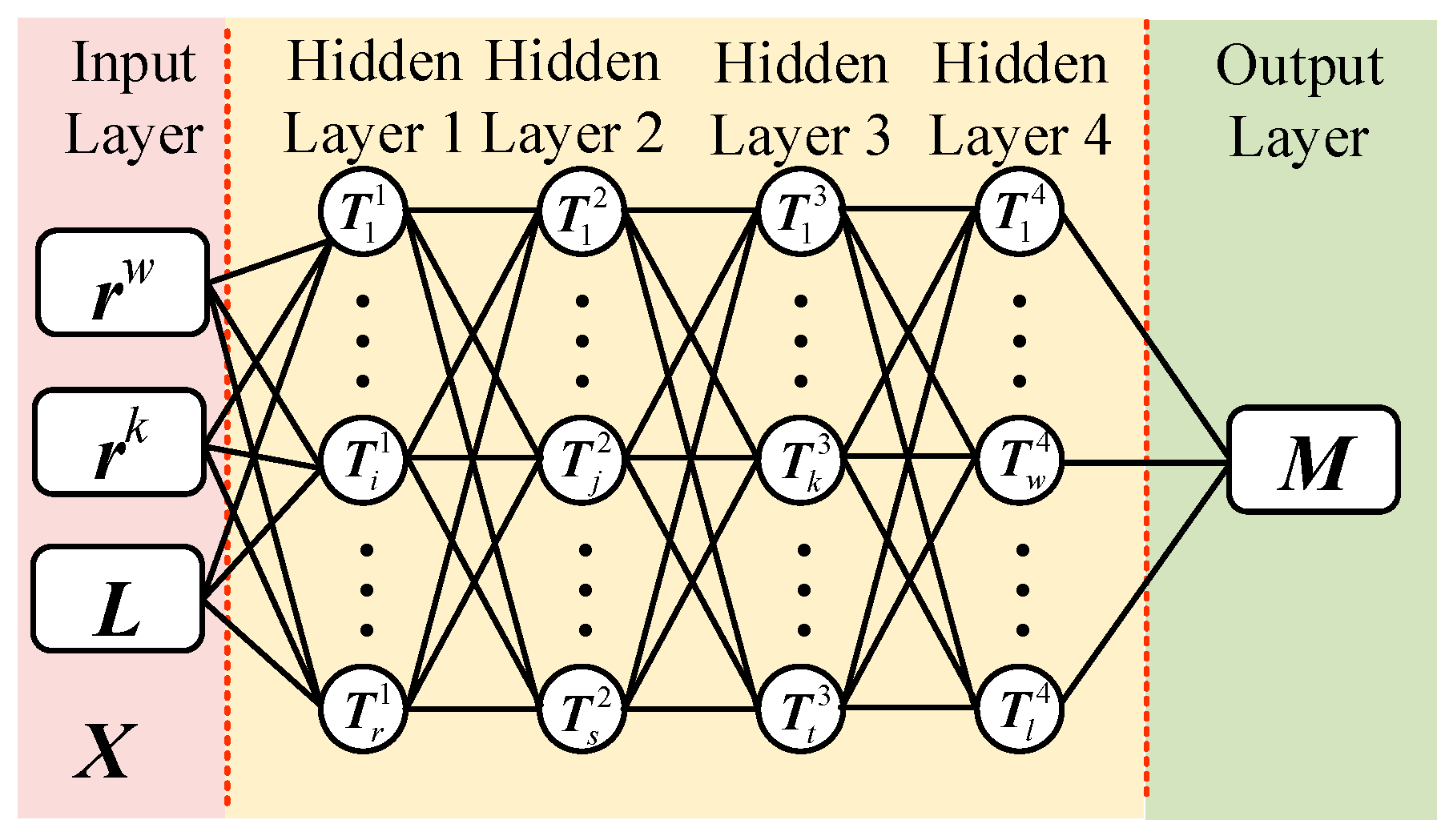
Figure 12 shows the schematic diagram of a deep neural network.
In
Figure 12,
is the input layer, where raw data is input, and each input node corresponds to a feature. In this paper, the aperture of the transmitting coil and the length of the receiving coil are used as the feature quantities for the calculation of the mutual inductance of the array-type coupler. Each input node represents the aperture and coil length of different structures, and the input layer depends on the number of feature quantities.
,
,
, and
are four hidden layers. The number of hidden layers and the number of neurons in each layer are selected based on specific problems. Multiple hidden layers enable the network to solve more complex problems. Each layer performs some abstraction and transformation on the input, gradually extracting higher-level features. However, too many hidden layers will lead to long calculation times, a waste of computational resources, and overfitting issues.
is the output layer, and the number of output layers depends on the combination of the coupler set of
.
3.1. Forward Propagation of Deep Neural Network
Forward propagation is the process of transmitting the aperture of the transmitting coil and the length of the receiving coil from the input layer to the output layer and generating the mutual inductance results. Through the weights and activation functions between layers, the network can gradually transform the input data, extract input data features, and ultimately generate output data. Forward propagation is crucial in the inference phase, and its effectiveness depends on the network’s weights and structure.
First, data processing is performed on the aperture size and receiving coil length using the Min-Max normalization method to map the raw data to a specified range (0, 1). Assume the raw input parameters
X are
where
is the radius sequence of the circumscribed circle of a single transmitting coil,
is the transmitting coil aperture sequence, and
is the receiving coil length sequence.
,
, and
are the numbers of elements in the aperture sequence and receiving coil length sequence, respectively. Normalize each of these sequences separately.
In the forward propagation process, the input of each neuron is the output of the previous layer of neurons. The weighted sum is calculated by connecting the weights between the input layer of this neuron and the output layer of the previous layer of neurons, as illustrated in Equation (4).
In the equation,
is the intermediate variable matrix of hidden layer 1;
is the normalized input matrix based on the transmitting coil aperture and receiving coil length.
and
are the weight matrix and bias matrix, respectively, between the input layer and hidden layer 1, i.e.,
The represents the activation function of the hidden layer. This paper adopts the Sigmoid activation function to incorporate nonlinearity, allowing the neural network to acquire and model more complex functional relationships.
The activation function of the output layer uses SoftmaxLayer. This function converts the raw output of the network into a probability distribution, ensuring that the sum of the generation probabilities of all interconnections is 1. For the input vector, its activation function is
3.2. Back Propagation and Parameter Update of Deep Neural Network
The weights and biases in the matrix form in Equation (4) are initialized using the Xavier initialization method, which samples elements of the weight matrix from a Gaussian distribution with mean zero. The Xavier initialization method ensures that the output variance of each layer is similar to the input variance, thereby circumventing the issues of gradient explosion or gradient vanishing stemming from excessive or insufficient gradients. This ensures that the magnitude of parameter updates in each layer does not differ too much, thus accelerating convergence.
The Adam optimization algorithm is used to solve for weights and biases iteratively. This gradient-based optimization algorithm combines first-order and second-order moment estimates to adjust the learning rate adaptively. Therefore, after establishing the model, to ascertain the values of the weight matrix and bias matrix and , the model needs to be trained offline using a training dataset so that the calculation accuracy of the mutual inductance based on the deep neural network reaches the expected value.
To achieve the above purpose, different
,
, and
can be used to obtain a training dataset of mutual inductance values
. Subsequently, the training dataset is input into the model for offline training, and after training is completed, the recognition model is imported into the controller for online recognition. This paper employs the approach of using simulation software to establish a system simulation model to obtain the data required for training the above model. In order to make the training set data more reliable and reduce the uncertainty of the data, this paper constructs a finite element simulation model in COMSOL and Ansys, respectively, as shown in
Figure 13.
An array-type coupler structure is constructed using finite element simulation software, and by altering parameters
,
, and
during the simulation process, 2000 mutual inductance data points can be obtained, as illustrated by the data points in
Figure 9 and
Figure 10. To enhance the generalization capability of the deep neural network mutual inductance calculation model, 2000 data are randomly selected as the training set, and 500 data are selected as the test set. The test set does not participate in model training. It is only used to test the model’s recognition effect to verify the model’s generalization ability by inputting the training set data into the model and using the AdamOptimizer to optimize the parameters in the model based on the training error value. Considering the balance between the convergence speed of the model and the training accuracy, the initial learning rate is set to 0.005, and the maximum gradient threshold is set to 1, until the recognition error value decreases to the set value. After 7000 training iterations, the average absolute error and mean square error of the neural network model trained in this paper are 0.0112 and 0.01277, respectively. The model accuracy is sufficient to guide the design of array couplers and the error curve is illustrated in
Figure 14.
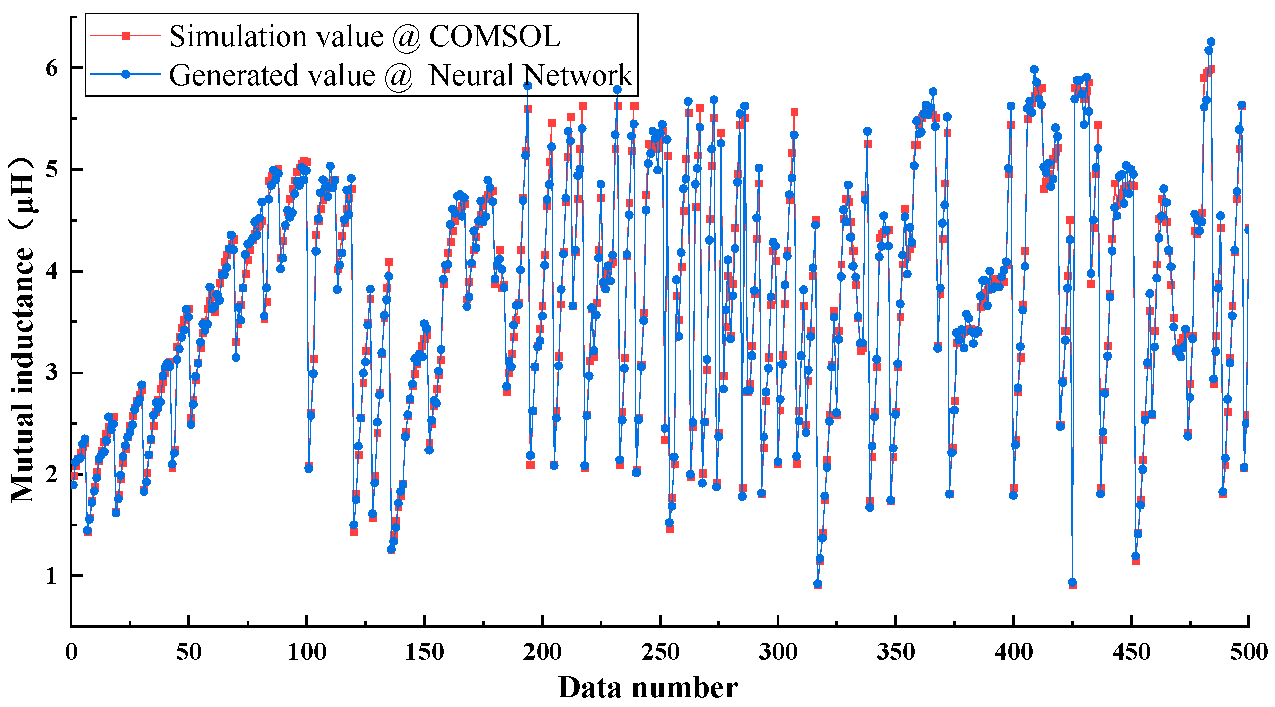
By exporting the values of the weight matrix and bias matrix, the trained model is substituted into the test set, and the comparison curve between the test set and the generated values can be obtained, as illustrated in
Figure 15. From the figure, it can be seen that the fitting degree of the 500 data points is high. These 500 data points are obtained by sampling from a data set of 2000 data points.
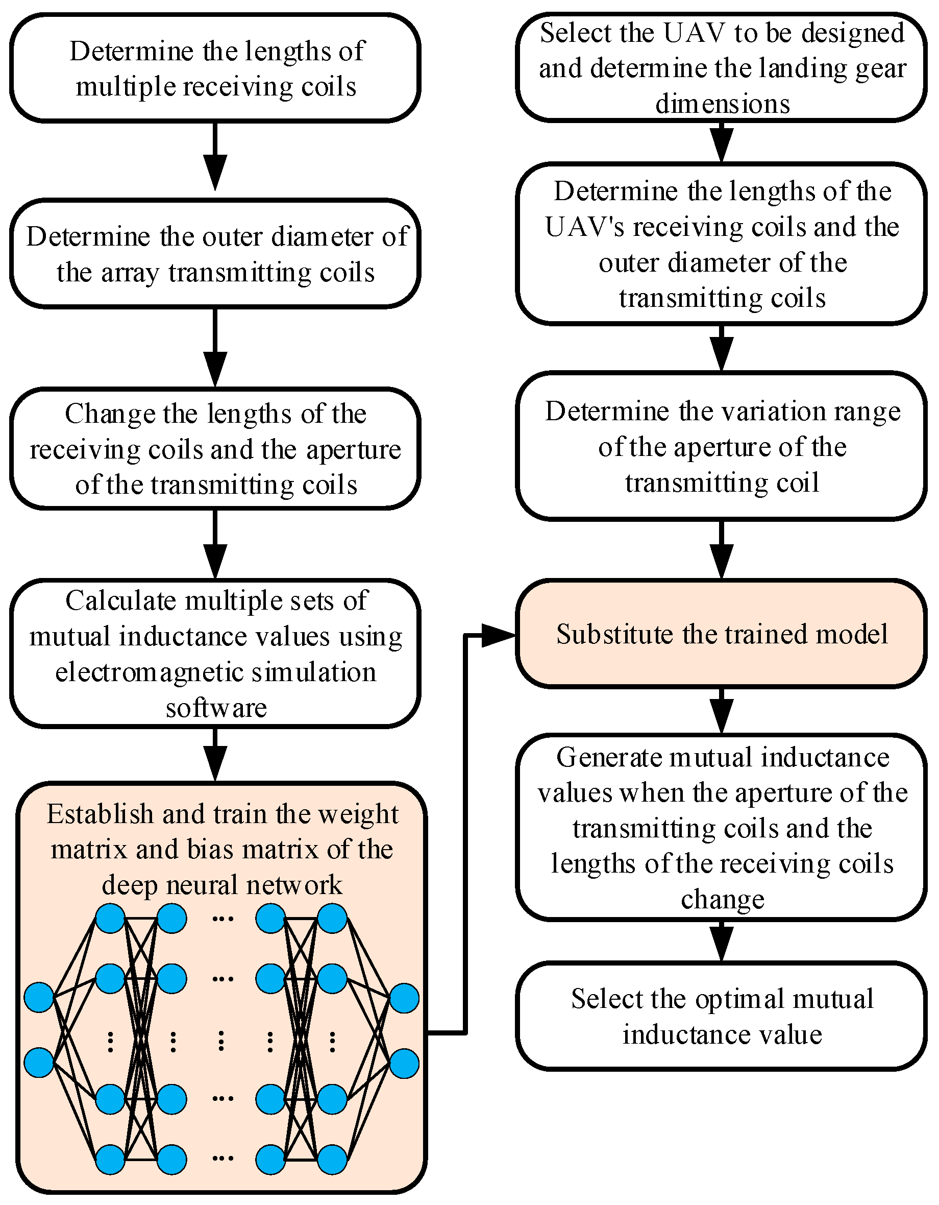
Therefore, when calculating the mutual inductance of an array coupler, consider that the larger the receiving coil size, the greater the coupler’s mutual inductance. Therefore, the length of the receiving coil
can be determined based on the width of the UAV’s landing gear. Subsequently, using Equation (1), the radius of the circumscribed circle of a single transmitting coil
can be calculated. Then, substituting
and
into the derived weight matrix and bias matrix for calculation, the mutual inductance value
can be obtained. The above design process and steps can be summarized as illustrated in
Figure 16.
5. Discussion
In the WPT system, mutual inductance is one of the core parameters that determines the energy transfer efficiency, and its magnitude directly affects the transmission power, system stability, and the working distance between coils [
24]. A well-designed mutual inductance not only enhances the magnetic flux linkage but also reduces energy loss, thereby improving the system’s adaptability under different flight attitudes and spatial positions. Therefore, modeling and optimizing around the variation of mutual inductance is of great significance for enhancing the practicality and robustness of WPT systems.
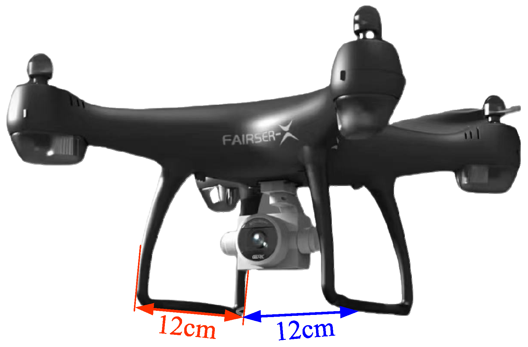
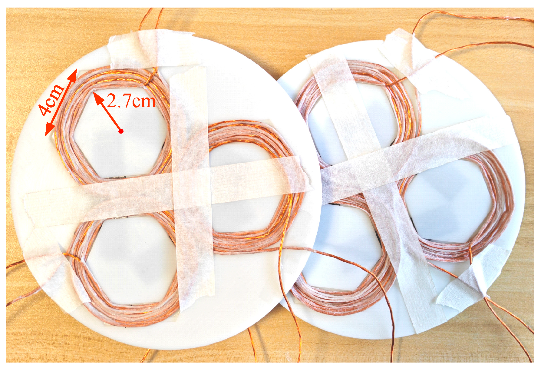
Based on the design method for array-type couplers proposed in this study using deep neural networks, this paper utilizes a trained deep learning model to design the structural parameters of the coupler. A prototype was produced based on the calculated optimized parameters of the coupler structure and is successfully applied to the wireless power transmission system for UAVs, validating its practicality on the FAIRSER-X type UAV. The results demonstrate that by using pre-trained data models, the optimal structural dimensions for mutual inductance of the coupler can be obtained rapidly and effectively, thereby enhancing the energy efficiency of wireless power transmission systems. This research accomplishment enhances the feasibility and advantages of using deep learning methods in modeling complex electromagnetic systems, particularly showing strong generalization capabilities for the adaptive design of array-type couplers in various UAV configurations. Compared to traditional trial-and-error design or singular parameter optimization methods, this approach significantly improves design efficiency and reduces dependence on repetitive testing of costly physical prototypes.
However, this study still has certain limitations. Firstly, the data used primarily originates from simulation models. Although preliminary verification has been achieved in experiments, factors such as electromagnetic interference and attitude changes in actual flight environments have not been fully considered. Secondly, the predictive accuracy of the designed neural network model needs further evaluation when confronted with new UAV structures outside the range of the training parameters. Finally, there is still a lack of standardized mutual inductance measurement protocols in the field of UAV wireless power transmission, and the evaluation system for mutual inductance and system energy efficiency must be formulated in conjunction with the power requirements of various UAV models. Therefore, future research could further incorporate multi-field coupling factors (such as temperature and electromagnetic interference) to enhance the model’s robustness and expand it to more complex three-dimensional flight trajectories and dynamic charging situations, thereby promoting the widespread application of WPT systems in UAV swarms or mobile platforms.
6. Conclusions
This paper conducts research on a WPT system for UAVs utilizing an array-type coupler. By analyzing the impact of variations in the dimensions of the transmitting coils and receiving coils on the mutual inductance of the coupler, it is revealed that the increase in mutual inductance follows a pattern where it first diminishes and then increases as the length of the receiving coil increases. Based on this pattern, the design relationship between the dimensions of the receiving coil and those of the three transmitting coil array units is clarified. Furthermore, when the length of the receiving coil and the inner circle radius of the transmitting coil are fixed, as the aperture of the transmitting coil increases, the mutual inductance of the coupler first increases and then decreases, indicating an optimal value. To quickly obtain this optimal value, this paper constructs a deep learning model consisting of four layers of neural networks. By training the model with data from COMSOL simulation results, the average absolute error and mean square error are only 0.0112 and 0.01277, respectively. Lastly, this paper establishes a measurement platform for the mutual inductance of the array-type coupler in the FAIRSER-X UAV WPT system for drones, achieving a measured mutual inductance of 4.23 μH, which is close to the model-generated value of 4.31 μH, thus verifying the feasibility and accuracy of the proposed method.
The research in this paper focuses on the design of magnetic couplers, aiming to explore a generalized method for engineering designers. This method does not require junior engineers to master finite element simulation software; they only need to use artificial intelligence tools to input parameters and obtain optimal results. Of course, this paper also has certain limitations: the study is based on the optimization design of the coupler. It thus does not consider the optimization of the overall performance of the UAV WPT system. Furthermore, the proposed deep learning method is built on the structure of array-type magnetic couplers, and further research is needed to study the adaptability of the proposed method to other coupler structures.


