Article

A Capacity-Constrained Weighted Clustering Algorithm for UAV Self-Organizing Networks Under Interference

1
School of Mechatronical Engineering, Beijing Institute of Technology, Beijing 100081, China
2
State Key Laboratory of Environment Characteristics and Effects for Near-Space, Beijing 100081, China
*
Author to whom correspondence should be addressed.
Drones 2025, 9(8), 527; https://doi.org/10.3390/drones9080527
Submission received: 12 June 2025 / Revised: 17 July 2025 / Accepted: 24 July 2025 / Published: 25 July 2025
(This article belongs to the Special Issue Unmanned Aerial Vehicles for Enhanced Emergency Response)

Abstract

Compared to traditional ad hoc networks, self-organizing networks of unmanned aerial vehicle (UAV) are characterized by high node mobility, vulnerability to interference, wide distribution range, and large network scale, which make network management and routing protocol operation more challenging. Cluster structures can be used to optimize network management and mitigate the impact of local topology changes on the entire network during collaborative task execution. To address the issue of cluster structure instability caused by the high mobility and vulnerability to interference in UAV networks, we propose a capacity-constrained weighted clustering algorithm for UAV self-organizing networks under interference. Specifically, a capacity-constrained partitioning algorithm based on K-means++ is developed to establish the initial node partitions. Then, a weighted cluster head (CH) and backup cluster head (BCH) selection algorithm is proposed, incorporating interference factors into the selection process. Additionally, a dynamic maintenance mechanism for the clustering network is introduced to enhance the stability and robustness of the network. Simulation results show that the algorithm achieves efficient node clustering under interference conditions, improving cluster load balancing, average cluster head maintenance time, and cluster head failure reconstruction time. Furthermore, the method demonstrates fast recovery capabilities in the event of node failures, making it more suitable for deployment in complex emergency rescue environments.

1. Introduction

Unmanned aerial vehicle (UAV) can be described as aerial platforms that, by integrating various applications, fulfill the requirement of replacing humans in different fields of work [1,2]. UAVs, with their high performance and mobility, play an important role across various industries [3,4]. In the field of UAV emergency rescue, the application of UAVs is becoming increasingly widespread and diversified. It is not limited to disaster area reconnaissance and information collection tasks but also plays an increasingly important role in areas such as casualty location, supply delivery, and environmental monitoring [5,6,7]. Especially with continuous advancements in technology and the accumulation of practical experience, UAVs have demonstrated increasingly exceptional performance in emergency rescue operations, establishing themselves as vital tools for enhancing the efficiency and effectiveness of rescue efforts [8].
However, despite the ability of individual UAV to respond quickly and execute tasks, their operational capabilities in complex battlefield environments remain limited. Autonomous UAVs, constrained by their limited sensing range, computational capacity, and mission load, often struggle to perform complex rescue tasks in the face of multiple task requirements and changing environments [9,10]. For example, under complex terrain, extreme weather conditions, or constantly changing task requirements, the effectiveness of a single UAV is severely limited, making it difficult to achieve coordinated actions, comprehensive situational awareness, or dynamic task adaptation. Thus, to overcome the limitations of a standalone UAV, collaborative networked rescue has become a key development focus. The UAV group realizes flexible dynamic task allocation through networking cooperation [11] and combines with the ground control station to improve the real-time and accuracy of data transmission with edge computing services [12,13]. Such a coordinated rescue mode not only improves task execution efficiency but also enhances adaptability and anti-interference capability in complex emergency environments, making it an important force in future emergency rescue operations.
Therefore, with the growing demand for collaborative task execution of the UAV, the development of a reliable communication network has become a key focus of research. The self-organizing networks formed by UAVs exhibit characteristics such as high node mobility and highly dynamic network topologies [14,15]. To fully exploit the advantages of the collaborative task execution, the network typically consists of a large number of nodes, wider spatial distribution, and greater network scale. Additionally, the emergency rescue scenarios faced by UAVs are often complex, involving multiple targets that require different groups to coordinate and complete specific tasks. In actual emergency rescue environments, the threat of interference against UAV self-organizing networks must also be considered. Such interference can affect a broad range of nodes or communication links, leading to significant changes in network topology and compromising the overall stability of the network [16].
The optimal solution to the aforementioned challenges is to partition the UAV network into multiple cluster structures, with each cluster responsible for executing different tasks. By dividing nodes into several clusters, each cluster can be regarded as a relatively stable sub-network [17,18]. Compared to flat network architectures, a clustered structure mitigates the impact of partial changes on the overall network. During the routing computation and generation process, only a subset of nodes needs to participate, which effectively reduces routing and control overhead. In addition, the clustered architecture enables more efficient network control and management, thereby enhancing overall network stability [19]. UAVs can achieve efficient deployment and stable communication in a clustered network structure. In such networks, each sub-cluster contains two types of nodes: cluster head and cluster member. The cluster head is the core node of the clustered network, responsible for information forwarding, routing management, and the coordination of both intra-cluster and global information. Its performance directly impacts the communication efficiency and stability of the entire network [20]. Therefore, the selection of cluster heads is a critical component in the design of clustering algorithms. However, existing clustering algorithms generally fail to address interference issues during the cluster head selection process. Therefore, it is essential to make corresponding improvements to the clustering algorithm to address anti-interference issues and enhance the stability of the network topology under interference conditions.
To tackle interference challenges, the paper introduces a capacity-constrained weighted clustering algorithm (CWCA) for UAV self-organizing networks under interference to ensure effective clustering performance and network stability under interference conditions. First, a capacity-constrained partitioning algorithm based on K-means++ is developed to partition the UAV nodes in the network. Second, we propose a cluster head (CH) and backup cluster head (BCH) selection algorithm, where node connectivity, remaining energy, mobility similarity, average intra-cluster distance, and external interference are all considered in the selection criteria. Furthermore, to improve the stability and robustness of the clustered network, a dynamic maintenance mechanism for the cluster network is introduced. The performance of the proposed CWCA is analyzed through simulations. Simulation results show that the scheme can achieve network clustering functionality and facilitate the dynamic update and maintenance of cluster structures under interference conditions. Additionally, it outperforms the benchmark clustering schemes from the literature in terms of intra-cluster load balancing, average cluster head lifetime under interference conditions, and cluster head failure reconstruction time. The core contributions of this study can be described as follows:
(1)
A capacity-constrained weighted clustering algorithm is proposed, which includes initial node partitioning, CH and BCH selection, and dynamic cluster maintenance. This method aims to improve the stability and robustness of UAV self-organizing networks in the interference environment.
(2)
A capacity-constrained partitioning algorithm based on K-means++ is designed, which considers both similarity-based partitioning and capacity balance, enabling the effective establishment of initial node partitions and addressing the problem of partition imbalance.
(3)
A weighted summation-based CH and BCH selection algorithm is proposed, which comprehensively considers factors such as connectivity, remaining energy, mobility similarity, average distance, and external interference to optimize the selection process.
(4)
The algorithm is validated through simulation experiments, with the results showing that the proposed clustering algorithm effectively performs network clustering in interference environments. A comprehensive evaluation is conducted by comparing it with baseline clustering schemes.
This article is structured as follows. Section 2 summarizes the related work. The clustering model for UAV systems is introduced in Section 3. The proposed capacity-constrained weighted clustering algorithm is presented in detail in Section 4. In Section 5, the performance of the CWCA is evaluated by simulations. Finally, Section 6 summarizes the contributions and future research directions of this study.

2. Related Works

Clustering refers to the process of dividing nodes into different clusters, with each cluster consisting of a cluster head and multiple cluster members. Nodes within a cluster have relatively stable communication connections with one another. Clustering helps alleviate communication load in the network, improves communication efficiency, reduces network energy consumption, and enhances network stability and reliability to some extent [21,22].
Several early traditional clustering algorithms are discussed in the literature [23,24,25], including the Lowest ID clustering algorithm (LID), Low Energy Adaptive Clustering Hierarchy clustering algorithm (LEACH), and Highest Degree clustering algorithm (HIGHD). The LID clustering algorithm selects the node with the smallest ID as the cluster head, which has the advantages of simple calculation and fast clustering speed. But it does not consider node mobility and load balancing. In high-dynamic, energy-limited network scenarios, the cluster structure is prone to fragmentation and reconstruction. The LEACH algorithm rotates the selection of cluster heads, with the advantage of energy load balancing, effectively reducing energy consumption. However, it is not suitable for large-scale networks, and the selection of cluster heads in this algorithm follows a single principle. The HIGHD algorithm selects the node with the highest degree as the cluster head. Its advantage is that it reduces the number of clusters in the network, thereby decreasing end-to-end delay. However, this algorithm suffers from issues such as a large number of cluster members, uneven communication resource distribution, and poor cluster structure stability.
In subsequent research, a Weighted Clustering Algorithm (WCA) was proposed, which integrates factors such as average inter-node distance, mobility, node degree, and energy, and is specifically designed for fully distributed and self-organizing network scenarios [26]. It makes the selection of cluster heads more reasonable and the adaptability of the scenario stronger. With the deepening of research, some researchers have been inspired by biological behavior to design AI-based bio-inspired algorithms and apply them to clustering, mainly including Ant Colony Optimization (ACO) [27], Gray Wolf Optimization (GWO) [28], and Particle Swarm Optimization (PSO) [29,30]. Although these methods offer strong global search capabilities and robustness, their slow convergence and high computational overhead make them unsuitable for time-sensitive, rapidly changing UAV networks in emergency rescue environments [31]. Therefore, considering the strict requirements of real-time performance, energy consumption, and dynamic topology for unmanned aerial vehicle emergency rescue networks, we choose to improve the clustering algorithm based on the weighted clustering method. The weighted clustering algorithm can map node degree, distance, mobility, and remaining energy to cluster head weights through a simple weighted model, achieving low complexity and fast convergence. At the same time, the weights can be flexibly tuned according to the scenario, without the need for a global iterative search. It is superior to biological heuristic algorithms in terms of energy consumption, parameter sensitivity, and stability, thus better ensuring the connectivity and service quality of the rescue network.
Based on the efficiency and scalability of the weighted clustering algorithm, numerous improved variants have been subsequently proposed by researchers both domestically and internationally. In ref. [32], a dynamic scale weighted clustering algorithm (DSWCA) was proposed, which dynamically adjusts the cluster scale based on its optimal, upper, and lower bounds and introduces a cluster head replacement threshold. This algorithm enables effective load balancing, extends the UAV formation survival cycle, and avoids frequent cluster reorganization and fusion. In ref. [33], an adaptive enhanced weighted clustering algorithm (AEWCA) was proposed, which optimizes the WCA by taking into account the optimal node degree and the distance between neighboring nodes when selecting the cluster head, together with the reliability of inter-node links and the energy consumption of nodes. This algorithm achieves the goals of balancing network energy consumption, extending network lifetime, and making combat time longer. In ref. [34], an improved weighted and location-based clustering algorithm (IWCA) was proposed, which uses a location-based K-means++ clustering algorithm to set up the initial UAV clusters and considers the remaining energy, node degree, relative mobility, and average distance as the cluster head selection principle. This scheme significantly improves performance, such as group delivery rate, network lifetime, cluster head replacement rate, and energy consumption. In ref. [35], a new routing scheme called the weighted cluster S-UAV routing scheme was proposed, which selects the cluster head and cluster members for each cluster based on a new weighted formula based on distance, speed, and reward index. This scheme reduces the total time delay of the network. In ref. [36], a dynamic weighted clustering algorithm (DWCA-DCH) was proposed, which selects the cluster heads by considering communication quality and remaining energy. This calculation balances communication efficiency and lifecycle, improving the survivability and stability of UAV cluster self-organizing networks.
The improved weighted clustering algorithm mentioned above can significantly extend network lifespan and improve communication efficiency by dynamically adjusting cluster size or position constraints. But the simulation task environment in the article is relatively ideal and does not focus on anti-interference issues. In highly dynamic UAV emergency-rescue scenarios subject to frequent interference, once the cluster head or critical link encounters interference, communication within the cluster may be completely paralyzed, resulting in delayed or erroneous rescue instructions, posing a serious threat to task safety. Therefore, it is necessary to introduce anti-interference mechanisms in weighted clustering algorithms and optimize them specifically for interference risks.

3. Clustering Model for UAV Systems

3.1. Network Topology Model

The network topology model of the UAV system is shown in Figure 1. In this system, the ground control station (GCS), UAV, and jammer are deployed. And it is assumed that each UAV integrates an inertial measurement unit (IMU), Global Positioning System (GPS) chipset, and a communication module to accurately measure speed and position information, while also enabling information exchange capabilities. During the task execution, UAVs are grouped into clusters according to the proposed clustering algorithm. The nodes participating in the task are divided into multiple clusters through a clustering algorithm, and different clusters are assigned to perform different tasks. Each cluster consists of different roles: the cluster head and the cluster members. Cluster members are further categorized into regular members and those with backup cluster head functions. The cluster head is responsible for managing clusters, communicating between different clusters, and communicating with external devices such as ground control centers. Cluster members can not directly communicate with nodes outside the cluster and must complete information collection and processing through cluster head forwarding. When the cluster head loses its working ability, the backup cluster head will take over its functions. After clustering, a dual power mode is adopted for cluster head nodes. Cluster head nodes use higher communication power for inter-cluster communication and lower power for intra-cluster communication to improve resource utilization and ensure successful information exchange.

3.2. Network Clustering Process

3.2.1. Information Exchange Process Between Nodes

In the network clustering process, the information exchange between nodes is mainly divided into five main phases: network partitioning, node neighbor discovery, cluster head and backup cluster head selection, cluster head invitation, and cluster member joining and confirmation. Each phase involves specific message exchanges that ensure efficient organization and stable operation of the network. During this process, five types of messages are primarily transmitted: Partition message, Hello message, C_Clustering message, C_Reply message, and C_Update message. The following is a brief overview of each message type:
  • Partition message: Sent by the ground control station to notify UAV nodes of the initial partitioning results and task information.
  • Hello message: Used for node sharing of basic information to perform initial partitioning, cluster head selection, and backup cluster head selection.
  • C_Clustering message: Sent by the cluster head node to inform other nodes within the partition to join its cluster.
  • C_Reply message: Used by cluster members to reply to the cluster head, informing it of new nodes joining the cluster.
  • C_Update message: Sent by the cluster head to notify all nodes within the cluster of the updated cluster member information.
Subsequently, we will provide a detailed description of the work processes for each phase, including the specific operations, message transmissions, and node interactions involved in each phase.
  • Network partitioning stage
Upon receiving the mission information, the ground control station obtains the location data of all nodes and performs initial regional partitioning of UAV nodes using a partitioning algorithm based on the number of tasks. The partitioning results are then broadcast to all nodes via Partition messages, which contain details such as node IDs and tasks for each partition. Upon receiving their respective partition information, nodes update the Cluster ID field in their Hello messages and store the corresponding partition node list.
2.
Node neighbor discovery stage
After partitioning, all nodes remain in a “pending” state. Each node periodically broadcasts Hello messages to perform neighbor discovery within its partition. These messages allow nodes to gather information such as the position, velocity, and residual energy of neighboring nodes. Based on this information, each node computes a local weight value using a predefined weighting formula and includes this weight in its subsequent Hello message broadcasts.
3.
CH and BCH node selection Stage
Nodes collect the weight values from neighboring nodes within the same partition via Hello messages and compare them with their own. The node with the highest weight is selected as the cluster head. In the case of equal weight values, the node with a greater number of neighbors is preferred. Both a primary cluster head and a backup cluster head are selected through this process.
4.
Cluster Head Invitation Phase
The selected cluster head broadcasts a C_Clustering message to invite other nodes to join the cluster. It then waits for incoming C_Reply messages from prospective cluster members. Upon receiving a C_Reply, the cluster head updates its member list and subsequently broadcasts a C_Update message to all confirmed cluster members. This message includes the updated member list and the assigned time slots for communication. A portion of the time slots is reserved for future node additions. The cluster head further compares the current cluster member list with the partition node list. If the number of joined members does not meet the predefined threshold, it will re-broadcast the C_Clustering message repeatedly until the required number is met or the clustering time limit is reached.
5.
Cluster Member Joining and Confirmation Phase
Backup cluster heads and candidate member nodes listen for C_Clustering messages. Upon receiving such a message from a recognized cluster head in the same partition, a node sends a unicast C_Reply message to the cluster head indicating its intention to join. The node then waits for a C_Update message containing the finalized member list. If the node finds its ID included in the list, it successfully joins the cluster. Otherwise, if no C_Update is received or the node is not listed, it will resend the C_Reply until the joining process is complete.
Once all nodes have completed the above procedures and joined their respective clusters, the clustering process of the UAV network is finalized, and the overall network topology is successfully established.
The communication overhead in the information exchange process is closely related to the number of nodes, information length, exchange frequency, and interference level. Specifically, the analysis of communication overhead can be simplified to studying the number of bits transmitted during the information interaction process. As the number of nodes, information length, and exchange frequency increase, the number of bits involved in each phase of the clustering process increases proportionally, resulting in communication overhead in these phases growing in direct proportion to the variables. When the interference increases, it causes the packet loss rate of the entire network to rise to p , which leads to the “total transmission count” of all communication messages increasing by a factor of 1 1 p compared to the original, thereby further amplifying the overall communication overhead.

3.2.2. Time Slot Allocation of Nodes

  • Time slot allocation in the network partitioning phase
During the network partitioning phase, the period T is divided into a GCS time slot and W task time slots, as illustrated in Figure 2. The GCS transmits information during its designated time slot and is responsible for dynamically managing the status of the slot. During the non-GCS time slots, each task node monitors the channel status to determine whether individual task time slots are idle or occupied. Upon detecting idle time slots, the node randomly selects one from the available idle slots to broadcast a Hello message. If a collision occurs, where multiple nodes attempt to broadcast in the same time slot, a backoff mechanism, such as binary exponential backoff, is triggered [37]. The conflicting nodes then perform a randomized delay before reselecting an idle time slot, repeating the process until a successful transmission is achieved.
2.
Time slot allocation in the neighbor discovery phase
During the neighbor discovery phase, in each cycle of duration T, the duration excluding the GCS time slot is divided into K equal-length time frames, each corresponding to one of the K network partitions, as illustrated in Figure 3. Each partition exclusively occupies its designated time frame for communication. Within each time frame, a fixed number L of time slots is further defined, where L is set to be greater than the number of nodes in the corresponding partition to reduce the probability of time slot collisions. During their assigned time frames, nodes first monitor the channel status to determine whether individual time slots are idle or occupied. Upon detecting idle slots, the node randomly selects one of the available idle slots to broadcast a Hello message. If a collision occurs, where multiple nodes attempt to broadcast in the same time slot, a backoff mechanism, such as binary exponential backoff, is triggered. The conflicting nodes then perform a randomized delay before reselecting an idle time slot, repeating the process until a successful transmission is achieved.
3.
Time slot allocation in the clustering phase
During the clustering phase, in each cycle of duration T, the duration excluding the GCS time slot is divided into K equal-length time frames, with each frame assigned to one of the K network partitions, as illustrated in Figure 4. Within each frame, a fixed number of N + M time slots is defined, where N is the number of nodes currently present in the corresponding partition, and M is a scenario-dependent redundant value dynamically generated to enhance scalability and reduce potential collisions. During their assigned frame, each cluster head, selected within the partition, is responsible for assigning fixed time slots to itself and its cluster members. To accommodate future node arrivals, a certain number of time slots are reserved as backup slots. These reserved slots are first allocated to newly joining nodes. In the absence of new nodes during a cycle, the backup slots can be opportunistically accessed by existing cluster members through contention, thereby improving channel utilization.

4. Design of a Capacity-Constrained Weighted Clustering Algorithm

4.1. Network Partition

After network initialization, a partitioning algorithm is applied to divide the UAV network into regions. Each region will function as a cluster in subsequent tasks, performing different tasks. In this section, the nodes are partitioned based on the K-means++ algorithm [38]. The K-means++ algorithm considers the distance when selecting the initial cluster centers, resulting in a more uniform distribution of initial centers. This approach helps to reduce inter-cluster interference and enhances the overall distribution uniformity of the clusters.
Considering the operational characteristics of the UAV network, it has strict requirements for efficient data transmission, low-latency task responses, and strong anti-interference capabilities. If the number of nodes within a cluster is too large, the cluster head will face excessive computational and communication burdens, which could lead to increased network latency and delayed information transmission. This could even result in inconsistent task coordination within the cluster, ultimately affecting operational efficiency. Furthermore, an overly large cluster is more likely to become a primary target for external interference, reducing the system’s security. Therefore, to enhance the network’s stability, communication efficiency, and anti-interference ability, it is necessary to limit the number of nodes within each partition, ensuring efficient communication within the partition and maintaining the system’s stability in complex environments. To address this, a capacity-constrained partitioning algorithm based on K-means++ is proposed. Compared to the traditional K-means++ algorithm, the improved K-means++ algorithm introduces additional constraints to limit the maximum number of nodes. It also adaptively relaxes these constraints for nodes that cannot be allocated in the first round, ultimately achieving balanced control of partition capacity. Furthermore, the algorithm ensures high-quality allocation results and stability by using a distance-based node partitioning allocation order. The process of this algorithm is controllable and highly transparent, making it particularly suitable for practical combat scenarios that need to consider both similarity-based partitioning and capacity balance. And it effectively addresses the potential partitioning imbalance that may arise in the traditional K-means++ algorithm. The process of the capacity-constrained K-means++ algorithm is shown in Figure 5.
Through the integration of processes, the detailed summary description of the steps is as follows:
Step 1: Randomly select a node in the network as the first partition center (seed node).
Step 2: Calculate the Euclidean distance from all unselected points to the center of the currently selected partition.
Step 3: Based on the square of the distance as the probability distribution, select a node from the unselected nodes with a larger distance from the selected partition center as the new partition center.
Step 4: Repeat steps 2–3 until the predetermined K partition centers are selected.
Step 5: Calculate the distances between all unselected nodes and K partition centers, and sort all points by their distance to the nearest partition center.
Step 6: In sorted order, start by allocating the points with the smallest distance, and sequentially assign them to the nearest cluster that has not yet reached its maximum capacity limit N max .
Step 7: For the points that cannot be allocated in the first round, a dynamic relaxation strategy is adopted: the initial relaxation capacity is set to N max + 1, and attempts to allocate unallocated points to underfilled clusters based on a distance-priority order. If there are still unallocated points, gradually increase the relaxation amplitude until the maximum relaxation value is reached or all points are allocated.
Step 8: Output the final partition results.
Where K represents the number of clusters to be partitioned, and N max denotes the maximum capacity limit for each partition, both of which can be pre-set according to the actual task requirements. The algorithm achieves balanced control of cluster sizes by using a distance-based sorting method and a dynamic capacity relaxation strategy, ensuring allocation quality while maintaining balance.
The pseudocode of the capacity-constrained partitioning algorithm is listed in Algorithm 1.
Algorithm 1. Capacity-constrained partitioning algorithm based on K-means++
Input: Total number of nodes numNodes, number of partitions numClusters, maximum number of nodes per partition maxNodes, relaxation of constraints relaxation, maximum constraint relaxation maxRelaxation
Output: Partition set P = { p a r t i t i o n 1 p a r t i t i o n 2 ,…,  p a r t i t i o n n u m C l u s t e r s }
//K-means++ initialization
1Randomly select a node as the first partition center
2for k = 2 to numClusters do
3  Select the next partition center based on distance
4end for
//Preliminary Node Allocation
5Calculate the distance from each node to the nearest cluster center
6Sort nodes by distance from smallest to largest in sortedNodeIndices[]
7for  j = 1 to numNodes do
8    i = sortedNodeIndices ( j )
9  Get the target partition
10  if number of nodes in partition <maxNodes do
11  Allocate node  i to the partition
12  end if
13end for
// Dynamic relaxation of allocation
14if unallocated nodes exist and relaxationmaxRelaxation do
15  Allow the number of nodes per partition to be maxNodesPerCluster + relaxation
16  Attempt to reassign unallocated nodes again
17  if there are still unallocated nodes do
18    relaxation = relaxation + 1
19  end if
20end if
21return Partition set P = { p a r t i t i o n 1 p a r t i t i o n 2 ,…,  p a r t i t i o n n u m C l u s t e r s }
In Algorithm 1, the analysis of time and space complexity is mainly divided into three stages: the initial partition center selection stage, the preliminary node allocation stage, and the dynamic allocation relaxation stage.
In the initial partition center selection stage, K-means++ is used to select k centers from n nodes, with a time complexity of O ( k n ) . In terms of space, it is necessary to maintain the cluster center index array, so the space complexity is O ( k ) .
In the preliminary node allocation stage, the first step is to settle the distance to the nearest center for all nodes, with a time complexity of O ( k n ) . Then, sort the nodes based on distance, with a time complexity of O ( n log n ) . Finally, perform linear scan allocation on the nodes with a time complexity of O ( n ) . So the total time complexity of this stage is O ( k n + n log n ) . In terms of space, it is necessary to maintain the distance array from the node to the nearest center and allocate the result array, so the space complexity is O ( n ) .
In the dynamic allocation relaxation stage, a constant number of allocation processes are executed for unallocated u nodes, so the time complexity of this stage is O ( k u ) . In terms of space, it is necessary to maintain a node allocation state array, so the space complexity is O ( n ) .
Overall, for the capacity-constrained partitioning algorithm based on K-means++, the time complexity is O ( k n ) + O ( k n + n log n ) + O ( k u ) = O ( k n + n log n + u n ) , and the space complexity is O ( k ) + O ( n ) + O ( n ) = O ( k + n ) .

4.2. CH and BCH Node Selection

After completing the initial partitioning, it enters the stage of selecting cluster heads and backup cluster heads. In a clustering-based topology, the cluster head acts as the hub for information exchange between nodes within the cluster and between clusters, playing a crucial role in enhancing the performance of UAV systems. Meanwhile, during the operation of UAV, there are issues such as high mobility and susceptibility to external interference, which can lead to frequent topology changes. Therefore, in order to achieve better network topology stability in interference environments, this paper introduces interference factors in the cluster head selection process and adopts the mechanism of backup cluster heads. In this paper, we comprehensively consider the key factors that affect the network performance of UAV systems and transform them into cluster head influence factors that are suitable for clustering topology structures, thus completing the design of the optimal cluster head selection algorithm. The cluster head selection factors include connectivity factor, remaining energy factor, mobility similarity factor, average distance factor, and external interference factor.
  • Connectivity Factor
In UAV networks, network connectivity is crucial as it directly affects the collaborative capabilities of nodes within the network and the success rate of data packet transmission in the network. The connectivity of a node is usually measured by the number of its neighbors, which is the number of other nodes that the node can directly communicate with. Assuming the number of neighbors of node i in this partition is n i , then the network connectivity of node i is C i = n i . For node i , if another node j is within its communication range, it is called a neighbor of the node i . Usually, neighbor relationships need to meet the following conditions [39]:
d ( i , j ) R max
where d ( i , j ) represents the distance between node i and j , and R max is the maximum transmission radius of wireless communication between nodes.
Therefore, the connectivity factor can be normalized as follows:
f C i = n i N k 1
where N k is the total number of nodes in this partition.
2.
Remaining energy factor
In UAV cluster network, the cluster head manages intra-cluster data communication as well as inter-cluster data forwarding. Due to its additional responsibilities, the cluster head experiences much higher energy consumption compared to ordinary members. Therefore, the initial remaining energy of nodes must be considered during the cluster head selection process. Assuming that the nodes in the network have the same energy storage capacity, the normalized remaining energy factor of candidate nodes is as follows:
f E i = E i r E i
where E i is the maximum energy of the node and E i r is the current remaining energy of the node.
In the execution of tasks, the energy consumption of a UAV system can usually be divided into several key components: flight energy consumption, communication energy consumption, and sensing and data processing energy consumption. This energy consumption should be considered comprehensively to more accurately calculate the remaining energy. The remaining energy of a node can be expressed as follows:
E i r = E i ( E i c o m m + E i f l i g h t + E i s e n s o r )
where E i represents the initial energy of the node, E i c o m m represents the communication energy consumption of the node, E i f l i g h t represents the flight energy consumption of the node, and E i s e n s o r represents the sensing energy consumption of the node.
The communication energy consumption of the node i can be expressed as follows:
E i c o m m = t × j = 1 D i w i j
where t represents the working duration, D i represents the number of neighboring nodes that the node maintains communication with, and w i j represents the average power consumption between the node i and the neighboring node j , which is related to the distance.
Assume that the UAV i flies at a constant speed v i but may have a direction of motion that varies over time, with the acceleration being perpendicular to the direction of velocity. The flight energy consumption [40] of the node i can be expressed as follows:
E i f l i g h t = ( b 1 v i 3 + b 2 v i ) × t f l i g h t + b 2 g 2 v i 0 t f l i g h t a ( t ) 2 d t
where b 1 and b 2 are two parameters related to the aircraft’s weight (including all its payloads), wing area, air density, a ( t ) is the acceleration, v i is the flight speed, g is the gravitational acceleration, and t f l i g h t is the flight duration.
The sensing and data processing energy consumption of the node i can be expressed as follows:
E i s e n s o r = P s e n s o r × t s e n s o r + P p r o c e s sin g × t p r o c e s sin g
where P s e n s o r is the average power consumed by the node i for perceiving target information, t s e n s o r is the duration of perception work, P p r o c e s sin g is the average power consumed by the node i for preprocessing the perceived information, and t p r o c e s sin g is the duration of the data preprocessing.
3.
Mobility similarity factor
In the UAV cluster network, the cluster head needs to maintain stable communication links with all cluster members. If the motion patterns of the cluster head and cluster members are similar, the distance fluctuations between the nodes can be reduced, thereby minimizing communication interruptions caused by rapid distance changes or signal attenuation. UAVs are equipped with Inertial Measurement Units (IMU) and Global Positioning Systems (GPS), which can provide information such as position, velocity, and acceleration [41]. In the overall design of the clustering topology construction algorithm, in order to maximize the network topology maintenance time, both the current instantaneous motion state and future movement trend of the nodes need to be considered. Therefore, this paper proposes a method to calculate the relative mobility of nodes in a three-dimensional coordinate system using velocity and acceleration information. The motion state of the node i within the cluster is shown in Figure 6, where includes velocity and acceleration.
The velocity components in the X, Y, and Z directions can be expressed as follows:
v i z = v i cos α i
v i x = v i sin α i cos θ i
v i y = v i sin α i sin θ i
where v i is the scalar value of the velocity of the node i at the moment, α i is the angle between the velocity of the node i and the Z-axis at the moment, and θ i is the angle between the XY-plane component of the velocity of the node i and the X-axis at the moment.
The average velocity difference between the node i and all other nodes within its cluster can be expressed as follows:
v i z ¯ = j = 1 , j i N v i cos α i v j cos α j N k 1
v i x ¯ = j = 1 , j i N v i sin α i cos θ i v j sin α j cos θ j N k 1
v i y ¯ = j = 1 , j i N v i sin α i sin θ i v j sin α j sin θ j N k 1
v i ¯ = v i x ¯ 2 + v i y ¯ 2 + v i z ¯ 2
where N k is the number of nodes in this cluster, v j represents the scalar value of the velocity of node j at the moment, α j represents the angle between the velocity of node j and the Z-axis at this moment, and θ j represents the angle between the velocity XY-plane component of node j and the X-axis at this moment.
After normalization, the velocity similarity factor can be expressed as follows:
f v i ¯ = v i ¯ v max = v i x ¯ 2 + v i y ¯ 2 + v i z ¯ 2 v max
where represents the value of the node’s maximum movement speed.
At the same time, considering the acceleration of each node, the nodes with smaller differences in acceleration will have more similar motion trajectories. Similar to the method for calculating velocity, the average acceleration difference between node i and all other nodes within its cluster can be expressed as follows:
a i z ¯ = j = 1 , j i N a i cos β i a j cos β j N k 1
a i x ¯ = j = 1 , j i N a i sin β i cos γ i v j sin β j cos γ j N k 1
a i y ¯ = j = 1 , j i N a i sin β i sin γ i v j sin β j sin γ j N k 1
a i ¯ = a i x ¯ 2 + a i y ¯ 2 + a i z ¯ 2
where a i and a j represent the scalar acceleration values of node i and j , and β i and β j represent the angles between the accelerations of nodes and the Z-axis, while γ i and γ j represent the angles between the acceleration XY-plane components of nodes and the X-axis.
At the same time, since acceleration is perpendicular to velocity, it only changes the direction of the node’s motion without altering the magnitude of the velocity, i.e., v · a = 0 . Therefore, for any node, the angle between the velocity and acceleration directions satisfies the following equation:
tan β i = cos α i sin α i cos ( θ i γ i )
After normalization, the acceleration similarity factor can be expressed as follows:
f a i ¯ = a i ¯ a max = a i x ¯ 2 + a i y ¯ 2 + a i z ¯ 2 a max
where a max represents the value of the node’s maximum movement speed.
Therefore, the mobility similarity factor can be expressed as follows:
f m i = ω 1 f v i ¯ + ω 2 f a i ¯
where ω 1 and ω 2 are empirical factors, and ω 1 + ω 2 = 1 .
4.
External interference factor
In emergency rescue environments, UAVs are often subjected to interference, which can be mainly categorized into two types: energy-based interference and information-based interference. For energy-based interference, when the interference power is low, the communication quality between nodes will decrease; when the interference power is high, it may lead to a complete disruption of the communication link between nodes. In contrast, information-based interference typically does not cause a communication link failure but rather degrades the communication quality by introducing erroneous data, resulting in transmission deviations that affect the accuracy of the data and communication efficiency.
When interference causes communication interruption between nodes, the node cannot broadcast Hello messages to other nodes, nor can it receive messages from other nodes. Therefore, it will not be able to participate in the clustering process, nor can it participate in cluster head competition. When interference only leads to a decrease in node communication quality, in order to ensure network fairness, the degree of interference can be measured by the packet error rate of Hello messages periodically broadcast by nodes. Nodes with high packet error rates indicate severe interference and poor communication quality. Therefore, the external interference factor of the node i can be normalized and represented by the packet error rate of its Hello message, which can be expressed as follows:
f E P R i = m M × 100 %
where m is the number of Hello message error packets received by the node i , and M is the total number of Hello message packets received by the node i .
5.
Average distance factor
In UAV network, the cluster head, as the central node of each cluster, is responsible for inter-cluster and external communication. The initial average distance between the cluster members and the cluster head directly impacts communication delay and energy consumption. A closer cluster head can exchange data with the nodes within the cluster more quickly, thereby improving network efficiency. Assuming that the node transmission power is the same and the maximum communication distance is the same, the average distance factor of the node can be normalized and expressed [34] as follows:
f D i ¯ = j = 1 , j i N ( x i x j ) 2 + ( y i y j ) 2 + ( z i z j ) 2 ( N k 1 ) D max
where ( x i , y i , z i ) and ( x j , y j , z j ) represent the three-dimensional position information of nodes i and j , respectively, and D max is the maximum distance between nodes within the partition.
In summary, after calculating the five cluster head selection factors, the clustering weight values of the candidate cluster head nodes are obtained through a weighting method. The node with the smallest weight value is selected as the cluster head node, and the node with the second smallest weight value is selected as the backup cluster head node. In case of equal weight values, the node connectivity is compared. The weight value calculation method is expressed as follows:
W i = ε 1 ( 1 f C i ) + ε 2 ( 1 f E i ) + ε 3 f m i + ε 4 f E P R i + ε 5 f D i ¯
where, W i represents the weight value of node i in the cluster head selection process, and ε 1 , ε 2 , ε 3 , ε 4 and ε 5 are the weight coefficients of the five cluster head selection factors, which must satisfy ε 1 + ε 2 + ε 3 + ε 4 + ε 5 = 1 . These coefficients can be dynamically selected based on the network environment.
The pseudocode of the cluster head and backup cluster head selection algorithm is listed in Algorithm 2.
Algorithm 2. Anti-interference weighted selection algorithm for CHs and BCHs
Input: Partition set P = { p a r t i t i o n 1 p a r t i t i o n 2 ,…,  p a r t i t i o n n u m C l u s t e r s }, node information nodes, number of partitions numClusters
Output:  CHs   and   BCHs   for   each   cluster   S C H = { C H 1 C H 2 ,  …,  C H n u m C l u s t e r s }, S B C H = { B C H 1 B C H 2 ,  …,  B C H n u m C l u s t e r s }
//Calculate node weights
1for  k = 1 to numClusters do
2   for   i p a r t i t i o n k do
3    Calculate the cluster head selection factors by nodes
4     Calculate   the   weight   W i
5  end for
6end for
//Select CHs and BCHs based on weights
7for  k = 1 to numClusters do
8  Nodes within the partition are sorted in descending order of weight
9    C H k  = number of the node with the minimum weight
10    B C H k  = number of the node with the second smallest weight
11  if there are nodes with the same weight do
12    Compare connectivity and select those with high connectivity
13  end if
14end for
15return  S C H  = { C H 1 C H 2 , …,  C H n u m C l u s t e r s }, S B C H  = { B C H 1 B C H 2 , …,  B C H n u m C l u s t e r s }
In Algorithm 2, the analysis of time and space complexity is mainly divided into two stages: the node weights calculation stage and the CHs/BCHs selection stage.
In the node weights calculation stage, it is necessary to calculate the weight of each node in each cluster, with a total of k clusters and n nodes. The time complexity is O ( n ) . In terms of space, it is necessary to maintain a weight array, so the space complexity is O ( n ) .
In the CHs/BCHs selection stage, it is necessary to sort the nodes within each cluster by weight. When the number of nodes in each cluster is approximately n k , the time complexity can be expressed as O ( n log ( n k ) ) . In terms of space, it is necessary to maintain sorting index arrays, cluster center arrays, and backup cluster center arrays. Therefore, the spatial complexity of this stage can be expressed as O ( n ) + O ( k ) + O ( k ) = O ( n + k ) .
Overall, for the anti-interference weighted selection algorithm for CHs and BCHs, the time complexity is O ( n ) + O ( n log ( n k ) ) = O ( n log ( n k ) ) , and the space complexity is O ( n ) + O ( n + k ) = O ( n + k ) .

4.3. Dynamic Maintenance of the Clustered Network

In emergency rescue environments involving UAV operations, both cluster head nodes and cluster member nodes may suddenly go offline due to various factors, such as interferences, equipment failures, battery depletion, or node mobility, leading to communication link disruptions. Meanwhile, after completing the network partitioning, the ground control station assigns task information to each node. Each node treats the target location as a waypoint and adjusts its trajectory accordingly. As a result, some nodes that were initially outside the communication range may later join an existing cluster as new members. Therefore, the dynamic updating and maintenance of the cluster structure are critical, as they ensure the stability of the network and efficient communication. The following section provides a detailed explanation of the dynamic maintenance mechanism for nodes.
  • Joining the cluster member node
When a new node, which may be either newly added to the network or have detached from its original cluster, needs to join the clustered network, it first receives Hello messages from nearby nodes. Subsequently, it sends a cluster join request (C_Reply message) to the cluster head node that is geographically closest to it. When the cluster head node receives this message, it updates the cluster member list, allocates a fixed time slot for the new cluster member in the backup time slot, and sends a C_Update cluster confirmation message. The new node receives the C_Update message and confirms that it is in the cluster member list, completing the cluster member joining. If a cluster member node does not receive the C_Update message after sending the C_Reply message, or if the C_Update message indicates that it has not been included in the cluster member list, it will retransmit the C_Reply message until the cluster membership is successfully completed.
2.
Offline of the cluster member node
The cluster head node monitors the connectivity of cluster member nodes by continuously listening for the Hello messages sent by the nodes. If it fails to receive the Hello message from a particular cluster member node for three consecutive times, the cluster head node determines that the link to this node has been disrupted and promptly updates its internal data, removing the failed node from the current cluster’s member list.
3.
Offline of the cluster head node
The backup cluster head node continuously monitors the Hello messages from the current cluster head node. If the backup cluster head node fails to receive the Hello message from the cluster head for three consecutive times, it is determined that the cluster head node has failed. At this point, the backup cluster head node automatically assumes the role of the new cluster head and broadcasts a C_Clustering message, notifying all member nodes within the original cluster to rejoin the new cluster structure. This process updates the entire cluster’s network topology, ensuring the normal operation and connectivity of the cluster.

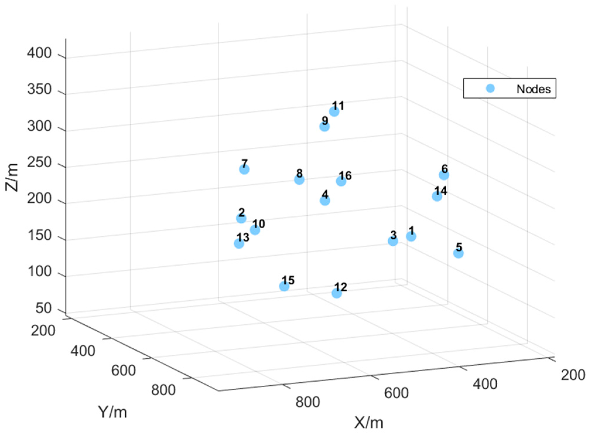
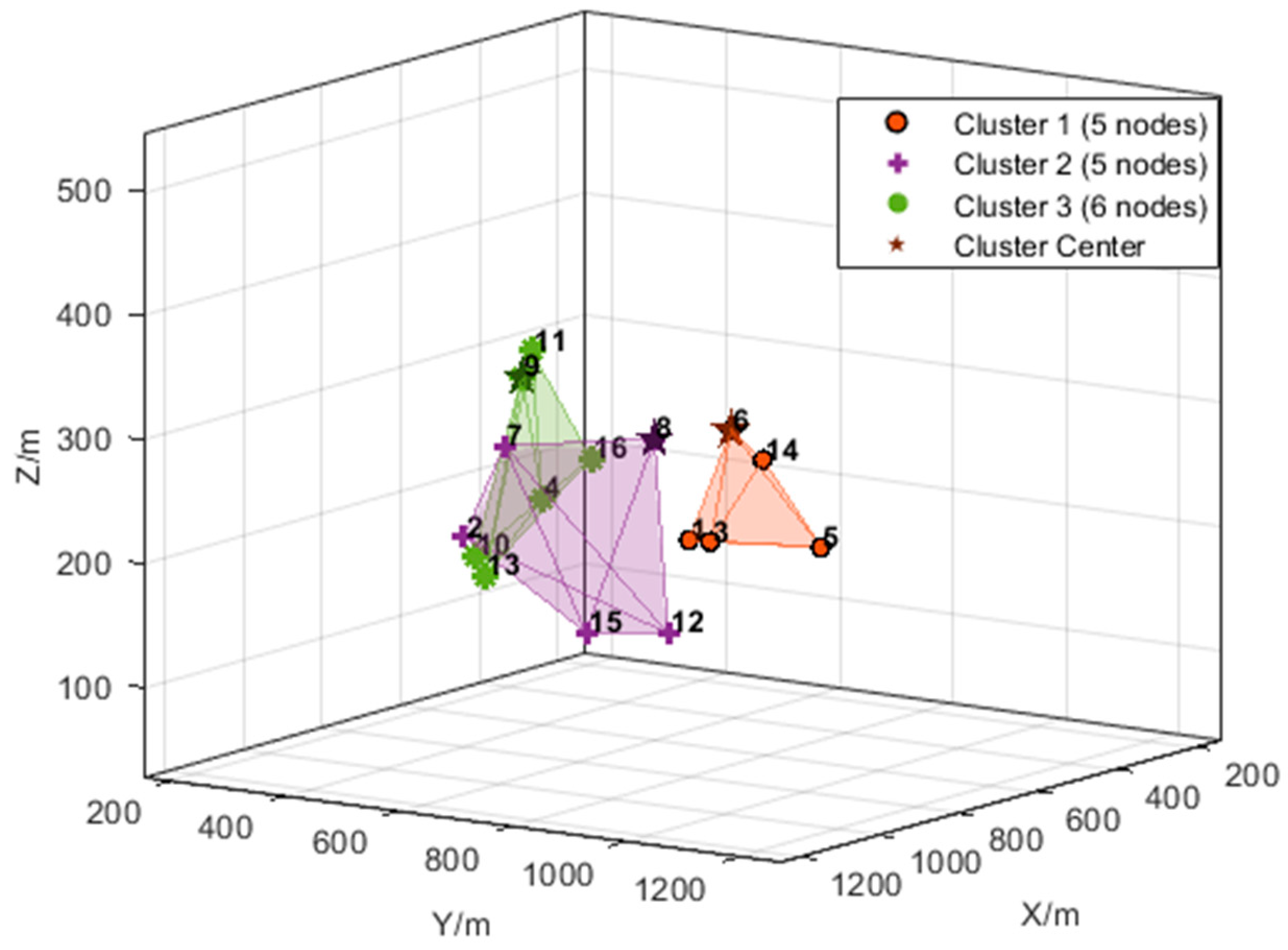
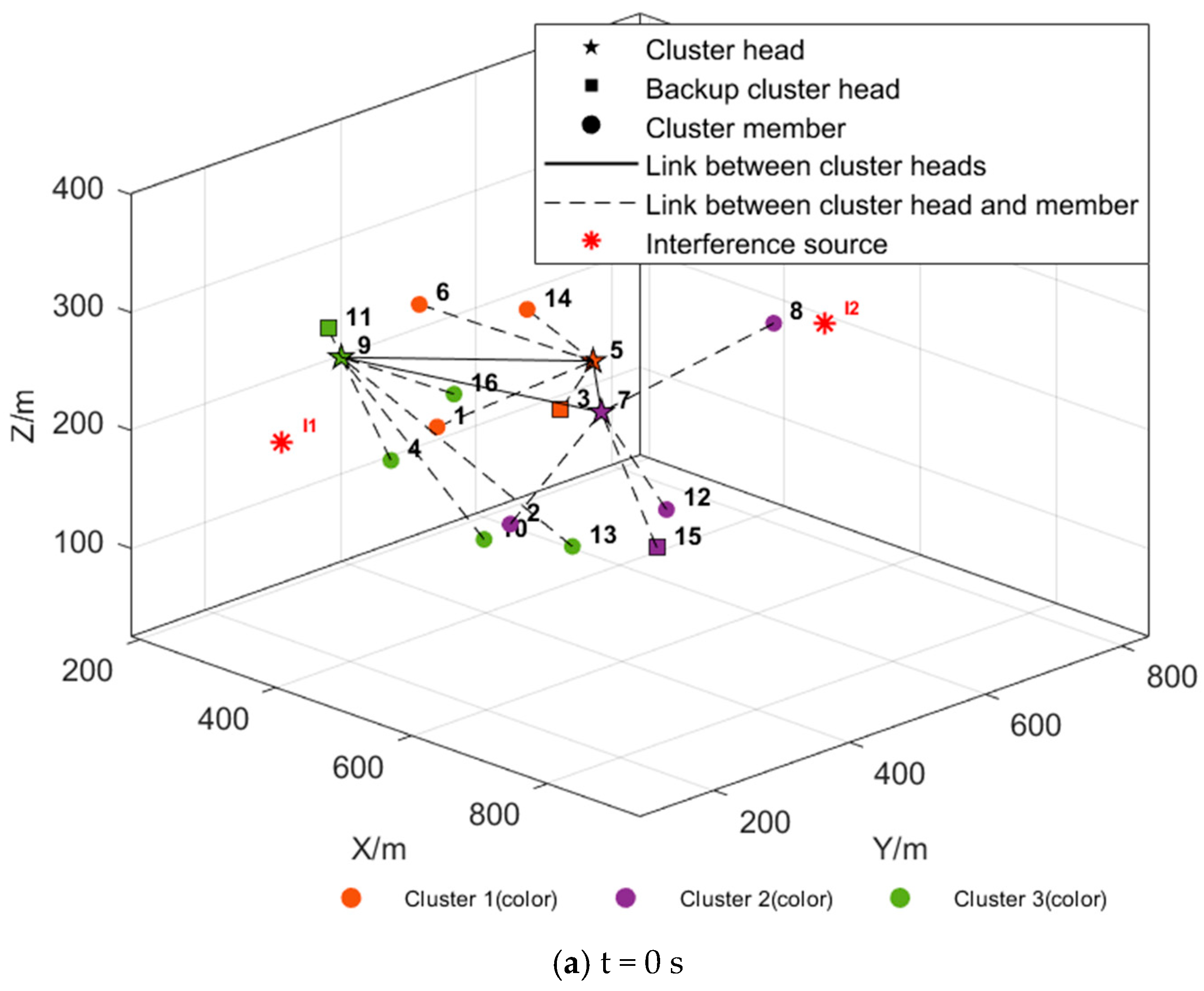
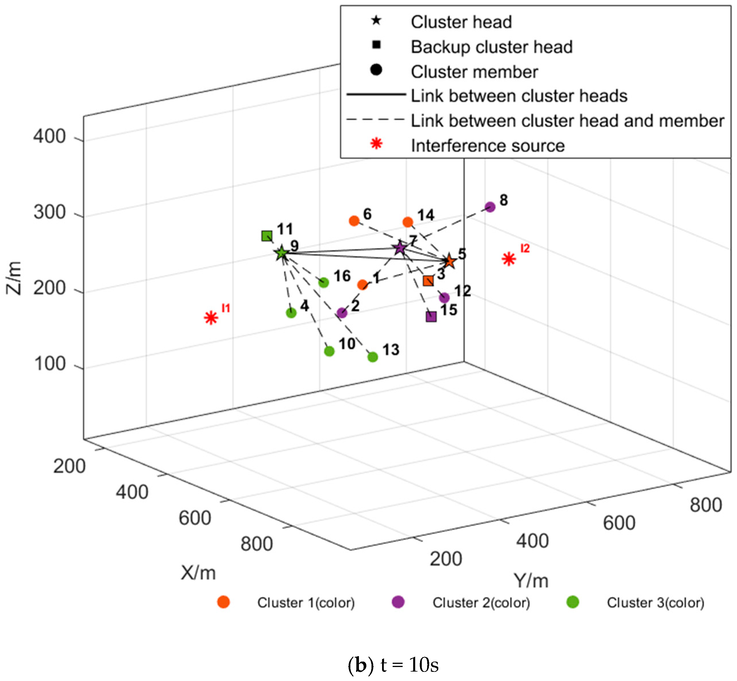
5. Simulation and Results

5.1. Simulation Parameter Settings

The simulation aims to evaluate the performance of the proposed improved anti-interference weighted clustering algorithm for UAV self-organizing networks. The specific settings can be found in Table 1. In the simulation, the area is set to 1000 × 1000 × 1000 m, with 16~300 nodes participating. The nodes move at speeds ranging between 20 and 30 m/s, and the acceleration is 5~10 m/s2. Each node starts with an initial energy of 100 J. The maximum communication distance between nodes within the cluster is limited to 300 m, and the maximum communication distance between cluster head nodes is limited to 600 m. In the subsequent anti-interference comparison simulation, the interference power increases in a gradient of 50 w.
In the simulation, the weighting coefficients for five key factors in CH and BCH selection are determined as follows and may be adjusted in future studies to suit specific operational requirements. The selection analysis of weighting coefficients is as follows:
  • External interference factor ( ε 4 = 0.3 ): The interference is a critical determinant of communication stability, especially in complex emergency rescue environments, where it can cause signal attenuation, data loss, and connection interruptions. To ensure that the system can effectively cope with interference and maintain communication stability, the weight of the external interference factor is set to 0.30, prioritizing nodes with strong anti-jamming capabilities during CH and BCH selection.
  • Connectivity Factor ( ε 1 = 0.25 ): The number of neighboring nodes directly affects network stability and scalability, since intra-cluster communication relies on the cluster head. So the cluster head should prioritize selecting UAVs that are connected to more neighbor nodes to ensure efficient communication. Based on this, the weight of the connectivity factor is set to 0.25 to ensure the selection of nodes with a larger number of neighboring nodes as the cluster head.
  • Average distance factor ( ε 5 = 0.2 ): Distance is an important factor influencing communication efficiency and energy consumption. Cluster heads tend to select nodes that are closer to others to reduce communication delay, improve signal quality, and lower energy consumption. Therefore, the weight of distance is set to 0.20 to ensure that cluster head selection optimizes communication quality and energy efficiency to the greatest extent.
  • Remaining energy factor ( ε 2 = 0.15 ): Remaining energy determines node longevity and overall network lifespan. To extend the network’s operational time and ensure system stability, the weight of the energy factor is set to 0.15, allowing the node’s energy state to be fully considered during cluster head selection.
  • Mobility similarity factor ( ε 3 = 0.1 ): Mobility affects cluster-head stability, since rapid speed differences can lead to frequent role changes. Considering that the speed difference between nodes is relatively small in this task scenario, the influence of mobility on cluster head selection is relatively small. So the weight of the mobility similarity factor is set to 0.10 to appropriately reflect the dynamic characteristics of the nodes during selection.
This section validates and analyzes the proposed algorithm, and compares it with IWCA [34], K-means++, WCA, and Random selection (RS) to ultimately verify the effectiveness and correctness of the algorithm proposed in this paper.

5.2. Clustering Network and Dynamic Maintenance Function Simulation

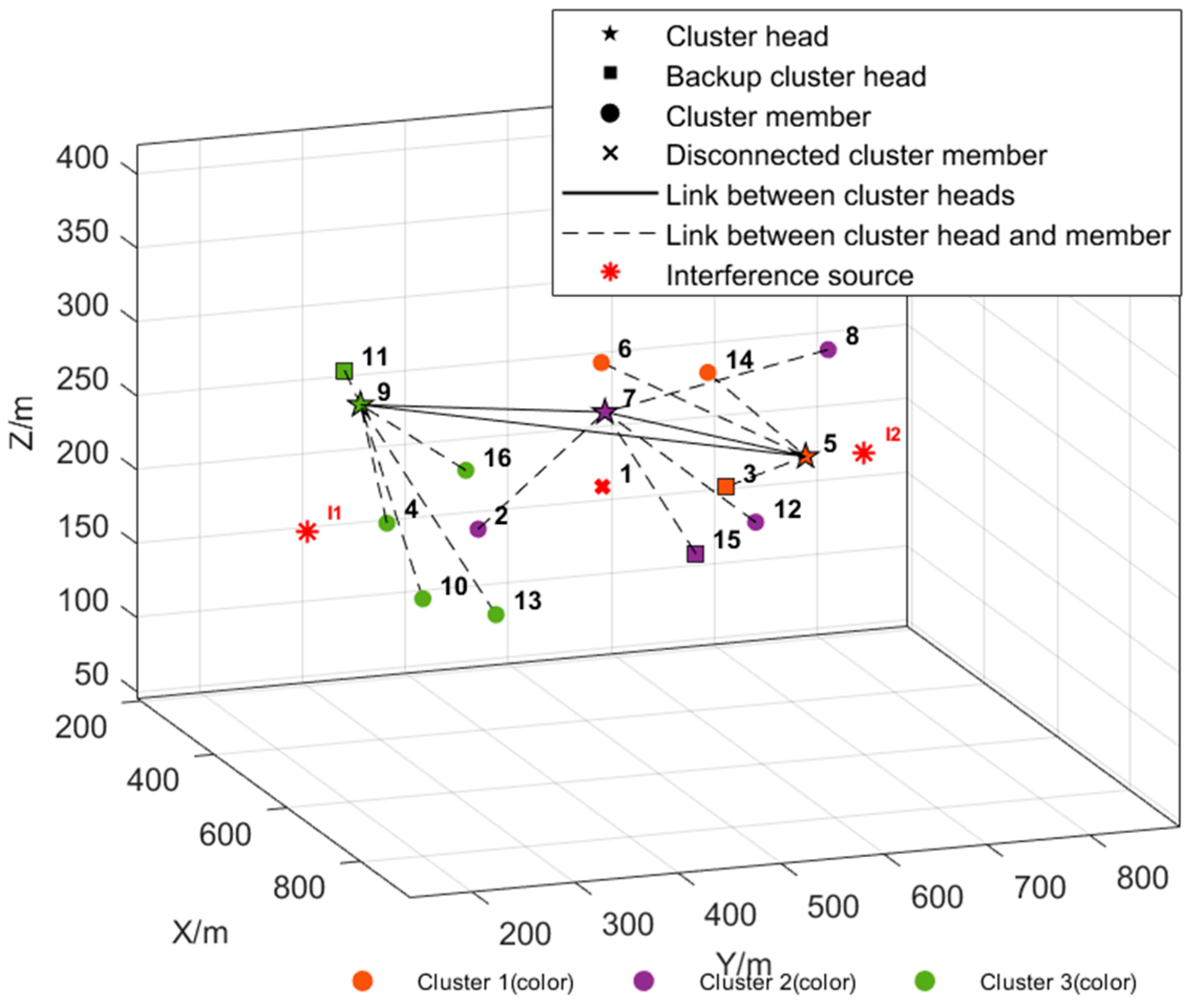
5.2.1. Simulation of Clustering Network Function

In this experiment, the network consists of 16 nodes, with the initial node distribution shown in Figure 7. To complete the mission, these nodes are divided into 3 clusters. To achieve this, we employed an improved K-means++ algorithm for partitioning. By considering both the node positions and the balance of node numbers within each cluster, the capacity-constrained K-means++ algorithm ensures an even distribution of nodes in space, minimizing interference between clusters. Figure 8 illustrates the partitioning result of this algorithm, which demonstrates that the node numbers within each cluster are effectively balanced, thereby achieving the goal of load balancing.
After the partitioning, a weighted algorithm was used to select the cluster head and backup cluster head for each partition, ultimately forming the network topology. Figure 9a shows the network topology formed after selecting the cluster heads and backup cluster heads, with the cluster head nodes being 9, 5, and 7, and the backup cluster head nodes being 11, 3, and 15. With the proposed clustering algorithm, all UAV nodes are interconnected through the cluster head nodes within the clustered structure, achieving efficient deployment and stable communication. Figure 9b displays the network topology after running for a period of time. It can be seen that even when the positions of the nodes change, the constructed network topology still ensures connectivity, demonstrating the effectiveness of the proposed algorithm.

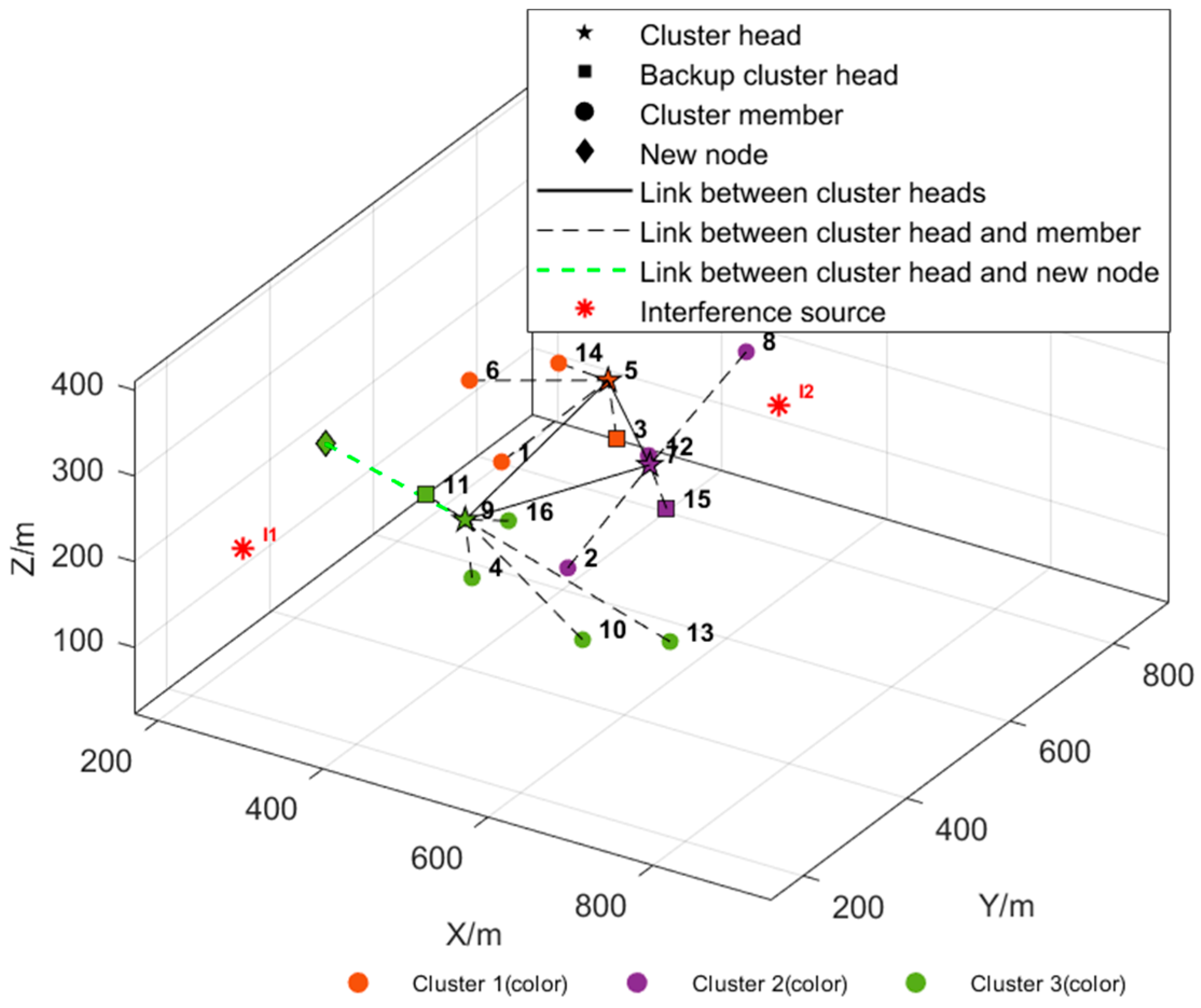
5.2.2. Simulation of Dynamic Maintenance Function Under Interference

4.
Cluster member disconnected
After running the simulation for 5 s, interference is simulated on the cluster member node 1, causing its communication link to be interrupted. The update and maintenance process of the cluster is shown in Figure 10. After the communication of the cluster member node 1 is interrupted, the cluster head node 5 removes the failed node from the current cluster’s member list, thereby completing the update of the network topology.
5.
Cluster head disconnected
After restoring the communication function of node 1, interference is simulated on cluster head node 7 after 5 s of simulation, causing its communication link to be interrupted. The update and maintenance process of the cluster is shown in Figure 11. After the communication of cluster head node 7 is interrupted, the backup cluster head node 15 automatically becomes the new cluster head, takes over the cluster, and reorganizes the other cluster members to join the cluster, thereby updating the entire cluster’s network topology and ensuring the normal operation and connectivity of the cluster.
6.
New Node Joining
After restoring the communication function of node 8, the simulation continues for 5 s, and a new node is added to the scene. The cluster update and maintenance process is shown in Figure 12. After the new node is added, it selects the nearest cluster head node 9 to complete the joining operation, thereby updating the network topology.

5.3. Analysis of Indicator Simulation Results

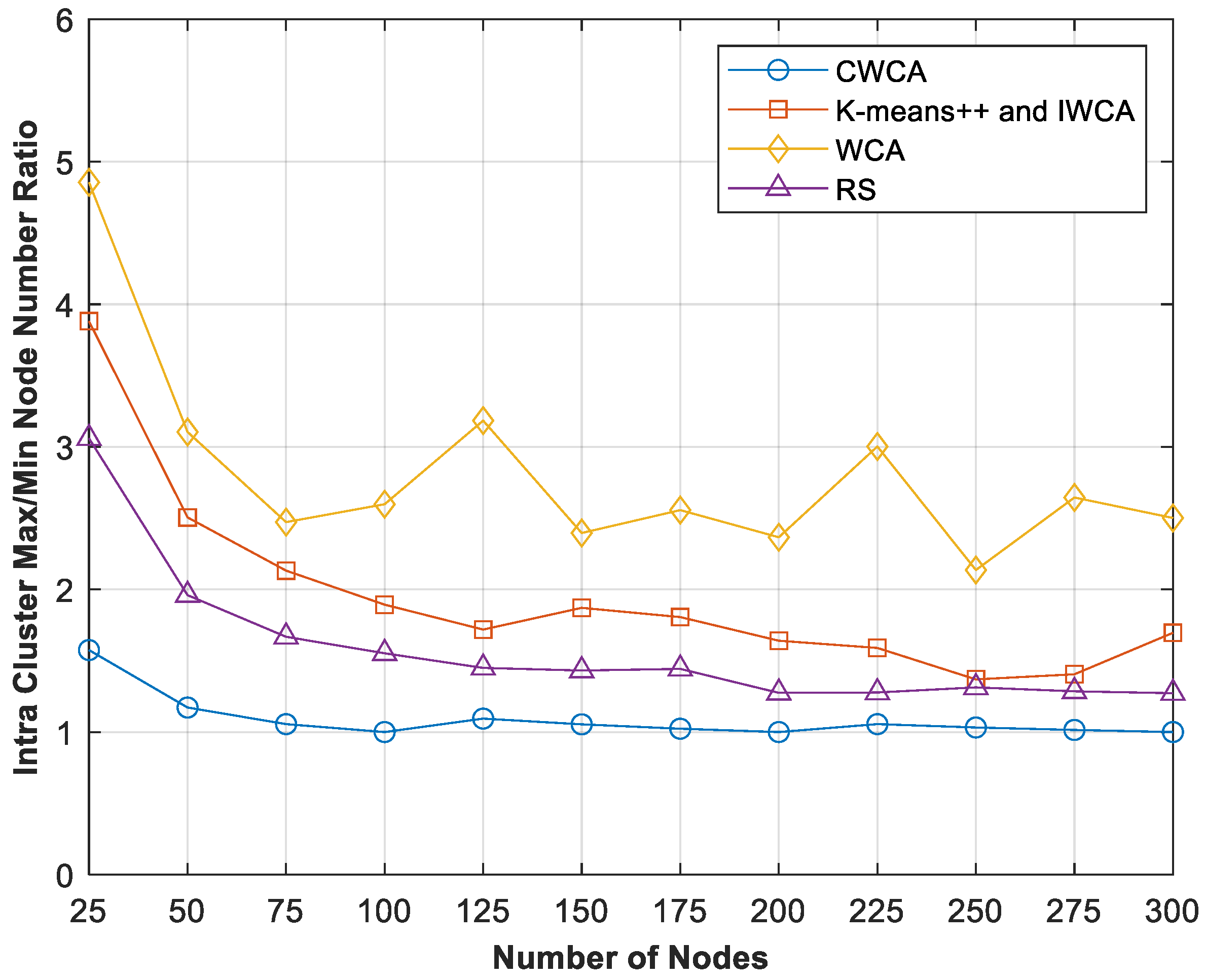
5.3.1. Balance of Intra-Cluster Node Distribution

Balance of intra-cluster node distribution is evaluated with the coefficient of variation (CV) of cluster sizes and the maximum-to-minimum node number ratio. The smaller the values, the more uniform the load and the lower the likelihood of CH overload. Limiting the number of nodes per cluster is therefore essential to prevent excessive network latency, untimely information delivery, and inconsistent task coordination. An oversized cluster not only imposes a heavy computational and communication burden on the CH but also becomes an attractive target for adversarial interference, thereby undermining system robustness and anti-interference capability.
Balance of intra-cluster node distribution of the algorithm was compared under different network scales. For each node count, the simulation was repeated 20 times, and the average value was taken. When comparing the five algorithms of CWCA, K-means++, WCA, IWCA, and RS at different network scales, CWCA consistently achieves the lowest CV and the smallest scale ratio, as shown in Figure 13 and Figure 14, demonstrating the optimal distribution balance of nodes within the cluster. RS ranks second on the single metric of node distribution balance by letting cluster sizes follow a multinomial distribution. However, it completely ignores node distance, link quality, and energy heterogeneity, resulting in excessive transmission distance, imbalanced energy consumption at CHs, and poor quality of service (QoS). In contrast, K-means++ focuses on geometric compactness, while WCA relies on cluster head weights to attract nodes during the clustering process. Both algorithms do not consider node distribution balance, often resulting in an extreme imbalance of large and small clusters in dense and sparse areas. Consequently, their node distribution balance performance is inferior to RS. IWCA is based on K-means++ for partitioning. After determining the number of clusters according to the node capacity, the number of nodes in each partition is the same as that in K-means++.
In summary, CWCA considers both the compactness of node geographical distribution and the ability to evaluate cluster heads during clustering, effectively suppressing the phenomenon of large/small clusters and avoiding the limitations of RS network performance. As a result, it performs the best in improving load balancing, system stability, and communication efficiency.

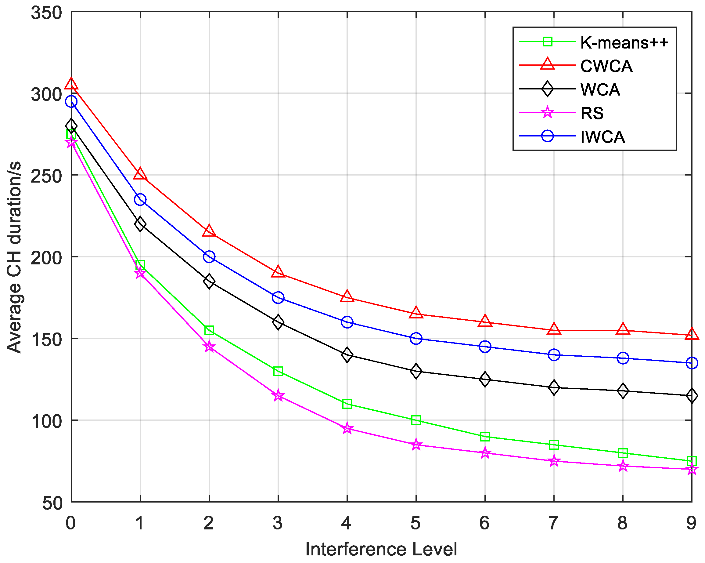
5.3.2. Average Cluster Head Duration Under Interference

The average cluster head duration is an important indicator for measuring the performance of cluster head selection algorithms. The longer the cluster head duration, the higher the stability of the cluster head, which helps to improve the reliability, resource allocation efficiency, and task coordination ability of the network. A longer cluster head duration can reduce the communication burden and energy consumption caused by frequent replacement of cluster heads, especially in interference environments, where the stability of cluster heads has a more significant impact on the overall performance of the system. As the level of interference increases, frequent changes in cluster heads can easily lead to network instability, which in turn affects task scheduling and data transmission. Therefore, comparing the average cluster head duration under different interference levels reveals the stability and interference tolerance of each algorithm.
We compared the average cluster head duration of CWCA, K-means++, WCA, RS, and IWCA algorithms in an environment with increasing simulated interference level in Figure 15. The number of nodes is set to 200, divided into 12 clusters. The simulation is repeated 20 times at each interference intensity to obtain the average simulation results. The results showed that the improved CWCA algorithm with external interference factors exhibited longer cluster head duration under various levels of interference conditions, significantly better than other algorithms, especially in high interference environments, indicating that the selected cluster heads were more stable and had stronger interference tolerance. Compared with the other algorithms, K-means++ relies on global spatial distribution to select initial cluster centers. Although it offers certain advantages in clustering efficiency, it lacks adaptability to node mobility and energy fluctuations, resulting in frequent changes of cluster heads. Consequently, its average cluster head duration remains relatively low among all evaluated algorithms and outperforms only the RS method. In contrast, the WCA algorithm incorporates multiple weighted factors such as node degree, residual energy, and mobility, which enhances its responsiveness to network state variations. This leads to a significantly longer cluster head duration compared with K-means++. Furthermore, the hybrid algorithm IWCA retains the spatial initialization advantage of K-means++ while integrating the multi-factor selection strategy of WCA, thereby improving the rationality and stability of cluster head selection. As a result, IWCA demonstrates superior overall performance among the four baseline algorithms and is second only to the proposed CWCA.

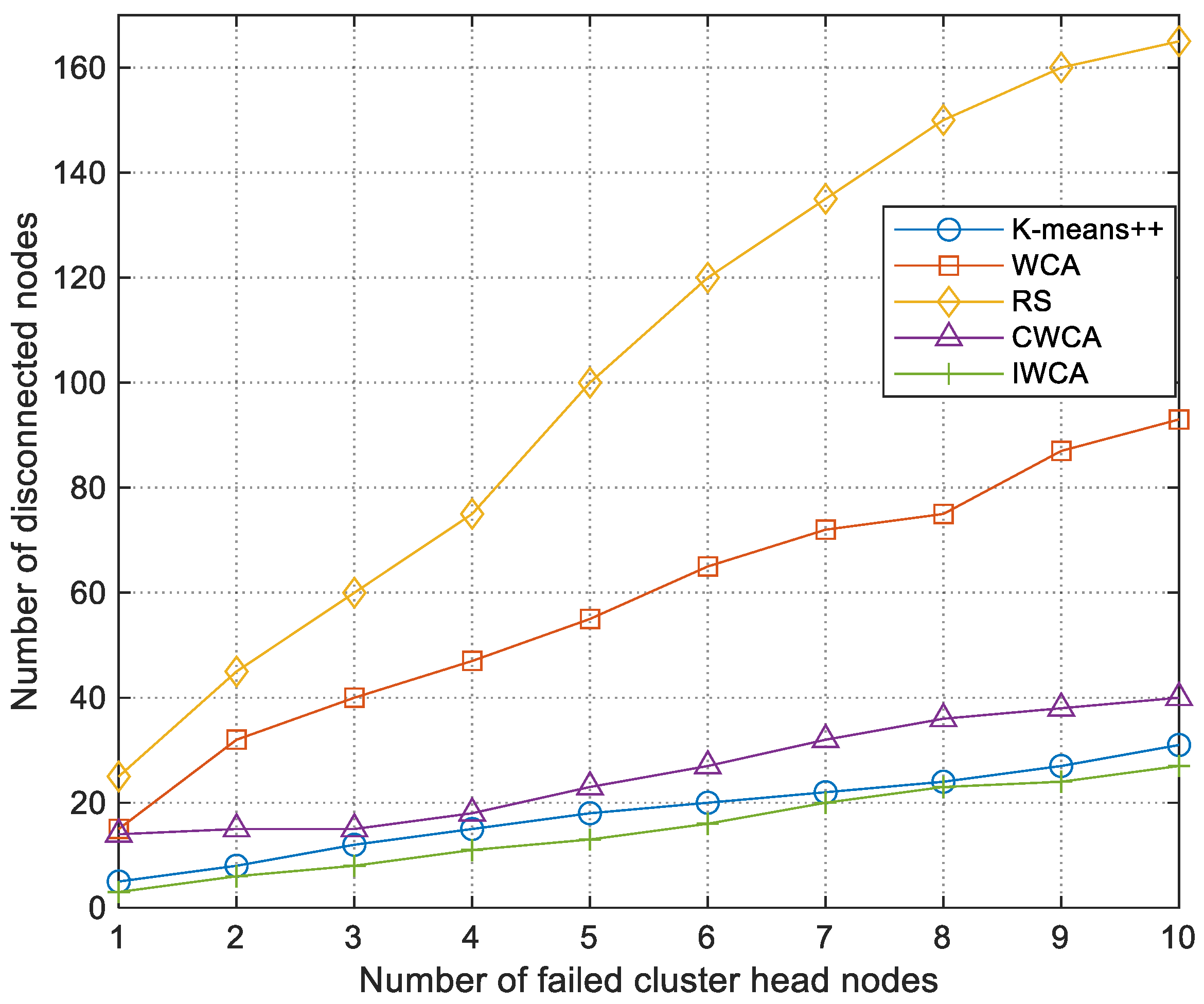
5.3.3. Reconstruction Performance of Cluster Head Failure Under Interference

To evaluate the reconstruction ability of various algorithms with cluster head failures caused by interference or collision in emergency rescue environments, we randomly disable selected cluster heads during the simulation process. In the simulation, 200 nodes are randomly distributed and divided into 10 clusters. The simulation is repeated 20 times at each number of dropped cluster head nodes to obtain the average value. Figure 16 and Figure 17 show the number of disconnected nodes and the reconfiguration time of the network after cluster head failure, respectively. Among them, dropped nodes refer to cluster members who are still unable to reconnect due to exceeding the communication range of the new cluster head after reconstruction is completed, and recovery time refers to the longest delay from the failure of the cluster head to the last cluster member rejoining the cluster. The disconnected node is the cluster member that, once reconfiguration ends, still lies outside the communication range of the new cluster head and therefore cannot rejoin. The reconfiguration time is the longest delay from the moment of cluster head failure to the instant the last member node rejoins the new cluster.
In terms of the recovery time, the proposed CWCA algorithm demonstrates the best performance compared to K-means++, WCA, RS, and IWCA. When the cluster head fails, the backup cluster head in CWCA can respond rapidly and directly take over the member nodes within the cluster, enabling swift recovery. In contrast, K-means++, WCA, IWCA, and RS require the reselection of the cluster head before reconstructing the cluster structure, which results in longer recovery times. Among them, IWCA has the most complex cluster head selection process, leading to the longest recovery time. The RS algorithm employs a random cluster head selection mechanism, and its recovery time ranks second only to CWCA.
Regarding the number of disconnected nodes, CWCA, K-means++, and IWCA all constrain the distance between nodes during initial clustering, thereby maintaining a relatively low and comparable level of node disconnection. In contrast, WCA and RS exhibit a significantly higher number of disconnected nodes, severely impairing network coverage. Although IWCA is also based on the K-means++ algorithm for initial partitioning, it reselects cluster heads within each partition using impact factors, resulting in slightly fewer disconnected nodes than the original K-means++. Because CWCA limits the number of nodes per partition, rather than strictly partitioning by distance, its performance in this aspect is slightly worse than k-means++.
In summary, CWCA has the shortest reconfiguration time and fewer disconnected nodes in the scenario of cluster head failure, demonstrating superior stability and interference resilience relative to the other algorithms.

6. Conclusions

This paper has addressed the challenge of interference in UAV self-organizing networks operating in complex emergency rescue scenarios. To improve network organization and management under such conditions, we proposed a capacity-constrained weighted clustering algorithm. The algorithm begins with a K-means++-based partitioning algorithm to form initial node partitions, then selects both the cluster head and backup cluster head by integrating the external interference factor into a weighted evaluation. A dynamic maintenance mechanism was also introduced to preserve cluster stability and robustness over time.
Simulation results demonstrate that, under interference conditions, our algorithm achieves more balanced cluster loads, extends average cluster head maintenance duration, and reduces recovery time following cluster head failures. Moreover, the network can rapidly recover from node disconnected, further enhancing its suitability for deployment in emergency rescue environments.
In this study, we focused on the design of clustering algorithms in interference environments. However, the study is subject to several limitations. In future work, we will conduct a more in-depth investigation of the weight coefficients employed in the CH and BCH selection process, optimizing these coefficients for each task scenario to enhance the clustering algorithm’s adaptability. Furthermore, we will build a hardware-in-the-loop simulation platform that integrates targeted routing protocol designs and various network optimization strategies, and we will explore FPGA and GPU acceleration schemes. Using this platform, we will conduct comprehensive evaluations of our algorithms’ real-time performance and energy efficiency to further improve system responsiveness and energy utilization. At the same time, we will carry out small-scale real-world flight tests to validate the reliability of the simulation results.

Author Contributions

Conceptualization, S.L. and P.G.; methodology, S.L. and X.G.; software, S.L. and J.L.; validation, S.L., J.L. and Z.F.; formal analysis, S.L. and P.G.; investigation, W.W. and X.G.; resources, W.W.; data curation, J.L. and Z.F.; writing—original draft preparation, S.L.; writing—review and editing, S.L. and Z.F.; visualization, S.L. and P.G.; supervision, W.W. and X.G.; project administration, P.G. and X.G.; funding acquisition, P.G. and X.G. All authors have read and agreed to the published version of the manuscript.

Funding

This work was funded by the National Natural Science Foundation of China (Grant No. 62472037) and the National Natural Science Foundation of China Youth Fund (Grant No. 62203048).

Data Availability Statement

The original contributions presented in the study are included in the article, further inquiries can be directed to the corresponding author.

Conflicts of Interest

The authors declare no conflicts of interest.

References

  1. Mohsan, S.A.H.; Othman, N.Q.H.; Li, Y.; Alsharif, M.H.; Khan, M.A. Unmanned Aerial Vehicles (UAVs): Practical Aspects, Applications, Open Challenges, Security Issues, and Future Trends. Intel. Serv. Robot. 2023, 16, 109–137. [Google Scholar] [CrossRef] [PubMed]
  2. Bekmezci, İ.; Sahingoz, O.K.; Temel, Ş. Flying Ad-Hoc Networks (FANETs): A Survey. Ad Hoc Netw. 2013, 11, 1254–1270. [Google Scholar] [CrossRef]
  3. Qamar, R.A.; Sarfraz, M.; Ghauri, S.A.; Mahmood, A. TRMaxAlloc: Maximum Task Allocation Using Reassignment Algorithm in Multi-UAV System. Comput. Commun. 2023, 206, 110–123. [Google Scholar] [CrossRef]
  4. Zhang, Y.; Gao, X.; Ye, N.; Niyato, D.; Han, Z.; Yang, K. Joint UAV Deployment, Power Allocation, and Coalition Formation for Physical Layer Security in Heterogeneous Networks. IEEE Trans. Veh. Technol. 2025, 74, 10994–11009. [Google Scholar] [CrossRef]
  5. Shah, Z.; Javed, U.; Naeem, M.; Zeadally, S.; Ejaz, W. Mobile Edge Computing (MEC)-Enabled UAV Placement and Computation Efficiency Maximization in Disaster Scenario. IEEE Trans. Veh. Technol. 2023, 72, 13406–13416. [Google Scholar] [CrossRef]
  6. Xu, J.; Ota, K.; Dong, M. Big Data on the Fly: UAV-Mounted Mobile Edge Computing for Disaster Management. IEEE Trans. Netw. Sci. Eng. 2020, 7, 2620–2630. [Google Scholar] [CrossRef]
  7. Sanz-Martos, S.; López-Franco, M.D.; Álvarez-García, C.; Granero-Moya, N.; López-Hens, J.M.; Cámara-Anguita, S.; Pancorbo-Hidalgo, P.L.; Comino-Sanz, I.M. Drone Applications for Emergency and Urgent Care: A Systematic Review. Prehospital Disaster Med. 2022, 37, 502–508. [Google Scholar] [CrossRef] [PubMed]
  8. Wang, Y.; Chen, W.; Luan, T.H.; Su, Z.; Xu, Q.; Li, R.; Chen, N. Task Offloading for Post-Disaster Rescue in Unmanned Aerial Vehicles Networks. IEEE/ACM Trans. Netw. 2022, 30, 1525–1539. [Google Scholar] [CrossRef]
  9. Oubbati, O.S.; Atiquzzaman, M.; Lorenz, P.; Tareque, H.; Hossain, S. Routing in Flying Ad Hoc Networks: Survey, Constraints, and Future Challenge Perspectives. IEEE Access 2019, 7, 81057–81105. [Google Scholar] [CrossRef]
  10. Mowla, N.I.; Tran, N.H.; Doh, I.; Chae, K. AFRL: Adaptive Federated Reinforcement Learning for Intelligent Jamming Defense in FANET. J. Commun. Netw. 2020, 22, 244–258. [Google Scholar] [CrossRef]
  11. Yasser, M.; Shalash, O.; Ismail, O. Optimized Decentralized Swarm Communication Algorithms for Efficient Task Allocation and Power Consumption in Swarm Robotics. Robotics 2024, 13, 66. [Google Scholar] [CrossRef]
  12. Li, Y.; Gao, X.; Shi, M.; Kang, J.; Niyato, D.; Yang, K. Dynamic Weighted Energy Minimization for Aerial Edge Computing Networks. IEEE Internet Things J. 2025, 12, 683–697. [Google Scholar] [CrossRef]
  13. Yang, K.; Wang, Y.; Gao, X.; Shi, C.; Huang, Y.; Yuan, H.; Shi, M. Communications in Space–Air–Ground Integrated Networks: An Overview. Space Sci. Technol. 2025, 5, 0199. [Google Scholar] [CrossRef]
  14. Chen, X.; Tang, J.; Lao, S. Review of Unmanned Aerial Vehicle Swarm Communication Architectures and Routing Protocols. Appl. Sci. 2020, 10, 3661. [Google Scholar] [CrossRef]
  15. Alzahrani, B.; Oubbati, O.S.; Barnawi, A.; Atiquzzaman, M.; Alghazzawi, D. UAV Assistance Paradigm: State-of-the-Art in Applications and Challenges. J. Netw. Comput. Appl. 2020, 166, 102706. [Google Scholar] [CrossRef]
  16. Zhang, Y.; Gao, X.; Shi, M.; Yuan, H.; Kang, J.; Niyato, D.; Yang, K. Robust Secure UAV Communications with the Aid of Jamming Beamforming. IEEE Trans. Commun. 2025. [Google Scholar] [CrossRef]
  17. Gheisari, M.; Abbasi, A.A.; Sayari, Z.; Rizvi, Q.; Asheralieva, A.; Banu, S.; Awaysheh, F.M.; Shah, S.B.H.; Raza, K.A. A Survey on Clustering Algorithms in Wireless Sensor Networks: Challenges, Research, and Trends. In Proceedings of the 2020 International Computer Symposium (ICS), Tainan, Taiwan, 17–19 December 2020; pp. 294–299. [Google Scholar]
  18. Geng, R.; Ji, R.; Zi, S. Research on Task Allocation of UAV Cluster Based on Particle Swarm Quantization Algorithm. Math. Biosci. Eng. 2022, 20, 18–33. [Google Scholar] [CrossRef]
  19. Aadil, F.; Ahsan, W.; Rehman, Z.U.; Shah, P.A.; Rho, S.; Mehmood, I. Clustering Algorithm for Internet of Vehicles (IoV) Based on Dragonfly Optimizer (CAVDO). J. Supercomput. 2018, 74, 4542–4567. [Google Scholar] [CrossRef]
  20. Liu, Y.; Li, Y.; Cheng, W.; Wang, W.; Yang, J. UAV-Assisted Cluster-Based Task Allocation for Mobile Crowdsensing in a Space–Air–Ground–Sea Integrated Network. Sensors 2023, 24, 208. [Google Scholar] [CrossRef]
  21. Yu, J.Y.; Chong, P.H.J. A Survey of Clustering Schemes for Mobile Ad Hoc Networks. IEEE Commun. Surv. Tutor. 2005, 7, 32–48. [Google Scholar] [CrossRef]
  22. Bharany, S.; Sharma, S.; Badotra, S.; Khalaf, O.I.; Alotaibi, Y.; Alghamdi, S.; Alassery, F. Energy-Efficient Clustering Scheme for Flying Ad-Hoc Networks Using an Optimized LEACH Protocol. Energies 2021, 14, 6016. [Google Scholar] [CrossRef]
  23. Lin, C.R.; Gerla, M. Adaptive Clustering for Mobile Wireless Networks. IEEE J. Sel. Areas Commun. 1997, 15, 1265–1275. [Google Scholar] [CrossRef]
  24. Amis, A.D.; Prakash, R. Load-Balancing Clusters in Wireless Ad Hoc Networks. In Proceedings of the Proceedings 3rd IEEE Symposium on Application-Specific Systems and Software Engineering Technology, Richardson, TX, USA, 24–25 March 2000; pp. 25–32. [Google Scholar]
  25. Gerla, M.; Tzu-Chieh Tsai, J. Multicluster, Mobile, Multimedia Radio Network. Wirel. Netw. 1995, 1, 255–265. [Google Scholar] [CrossRef]
  26. Chatterjee, M.; Das, S.K.; Turgut, D. WCA: A Weighted Clustering Algorithm for Mobile Ad Hoc Networks. Clust. Comput. 2002, 5, 193–204. [Google Scholar] [CrossRef]
  27. Aadil, F.; Bajwa, K.B.; Khan, S.; Chaudary, N.M.; Akram, A. CACONET: Ant Colony Optimization (ACO) Based Clustering Algorithm for VANET. PLoS ONE 2016, 11, e0154080. [Google Scholar] [CrossRef] [PubMed]
  28. Arafat, M.Y.; Moh, S. Bio-Inspired Approaches for Energy-Efficient Localization and Clustering in UAV Networks for Monitoring Wildfires in Remote Areas. IEEE Access 2021, 9, 18649–18669. [Google Scholar] [CrossRef]
  29. Ali, Z.A.; Han, Z.; Masood, R.J. Collective Motion and Self-Organization of a Swarm of UAVs: A Cluster-Based Architecture. Sensors 2021, 21, 3820. [Google Scholar] [CrossRef]
  30. Sun, G.; Qin, D.; Lan, T.; Ma, L. Research on Clustering Routing Protocol Based on Improved PSO in FANET. IEEE Sens. J. 2021, 21, 27168–27185. [Google Scholar] [CrossRef]
  31. Kaur, P.; Singh, A. Nature-Inspired Optimization Techniques in VANETs and FANETs: A Survey. In Proceedings of the Advanced Computational and Communication Paradigms, Sikkim, India, 8–10 September 2017; Bhattacharyya, S., Chaki, N., Konar, D., Chakraborty, U.K., Singh, C.T., Eds.; Springer: Singapore, 2018; pp. 651–663. [Google Scholar]
  32. Wang, X.; Liu, Z.; Jian, C.; Shi, S.; Gu, J.; Shi, F. A Dynamic Scale UAV Weighted Clustering Algorithm. In Proceedings of the 2021 IEEE International Conference on Unmanned Systems (ICUS), Beijing, China, 15–17 October 2021; pp. 209–213. [Google Scholar]
  33. Sun, Y.; Mi, Z.; Wang, H.; Lu, F.; Zhao, N. Adaptive Enhanced Weighted Clustering Algorithm for UAV Swarm. In Proceedings of the 2020 IEEE 20th International Conference on Communication Technology (ICCT), Nanning, China, 28–31 October 2020; pp. 709–714. [Google Scholar]
  34. Yang, X.; Yu, T.; Chen, Z.; Yang, J.; Hu, J.; Wu, Y. An Improved Weighted and Location-Based Clustering Scheme for Flying Ad Hoc Networks. Sensors 2022, 22, 3236. [Google Scholar] [CrossRef]
  35. Khayat, G.; Mavromoustakis, C.X.; Pitsillides, A.; Batalla, J.M.; Markakis, E.K.; Mastorakis, G. On the Weighted Cluster S-UAV Scheme Using Latency-Oriented Trust. IEEE Access 2023, 11, 56310–56323. [Google Scholar] [CrossRef]
  36. Zhang, Y.; Hu, Z.; Wang, Z.; Wen, X.; Lu, Z. Survivability Analysis of Unmanned Aerial Vehicle Network Based on Dynamic Weighted Clustering Algorithm with Dual Cluster Heads. Electronics 2023, 12, 1743. [Google Scholar] [CrossRef]
  37. Ye, Y.; Zhang, X.; Xie, L.; Qin, K. A Dynamic TDMA Scheduling Strategy for MANETs Based on Service Priority. Sensors 2020, 20, 7218. [Google Scholar] [CrossRef]
  38. Arthur, D.; Vassilvitskii, S. K-Means++: The Advantages of Careful Seeding; Society for Industrial and Applied Mathematics: New Orleans, LA, USA, 2007; pp. 1027–1035. [Google Scholar]
  39. Gupta, P.; Kumar, P.R. The Capacity of Wireless Networks. IEEE Trans. Inf. Theory 2000, 46, 388–404. [Google Scholar] [CrossRef]
  40. Zeng, Y.; Zhang, R. Energy-Efficient UAV Communication with Trajectory Optimization. IEEE Trans. Wirel. Commun. 2017, 16, 3747–3760. [Google Scholar] [CrossRef]
  41. Zhou, Y.; Tang, D.; Zhou, H.; Xiang, X. Moving Target Geolocation and Trajectory Prediction Using a Fixed-Wing UAV in Cluttered Environments. Remote Sens. 2025, 17, 969. [Google Scholar] [CrossRef]
Figure 1. System model.
Drones 09 00527 g001
Figure 2. Time slot allocation in the network partitioning phase.
Drones 09 00527 g002
Figure 3. Time slot allocation in the neighbor discovery phase.
Drones 09 00527 g003
Figure 4. Time slot allocation in the clustering phase.
Drones 09 00527 g004
Figure 5. Partition algorithm process.
Drones 09 00527 g005
Figure 6. Motion state of the node.
Drones 09 00527 g006
Figure 7. Initial node distribution.
Drones 09 00527 g007
Figure 8. Node distribution after partitioning.
Drones 09 00527 g008
Figure 9. Final network topology based on clustering algorithm.
Drones 09 00527 g009aDrones 09 00527 g009b
Figure 10. Cluster member disconnected.
Drones 09 00527 g010
Figure 11. Cluster head replacement.
Drones 09 00527 g011
Figure 12. New node joining.
Drones 09 00527 g012
Figure 13. The coefficient of variation of nodes within the cluster.
Drones 09 00527 g013
Figure 14. The ratio of the maximum and minimum number of nodes within the cluster.
Drones 09 00527 g014
Figure 15. Average cluster head duration.
Drones 09 00527 g015
Figure 16. Reconfiguration time after cluster head failure.
Drones 09 00527 g016
Figure 17. Number of disconnected nodes after cluster head failure.
Drones 09 00527 g017
Table 1. Simulation parameter settings.
Parameter TypeSetting
Simulation area1000 × 1000 × 1000 m
Number of nodes16~300
Speed20~30 m/s
Acceleration5~10 m/s2
Initial energy100 J
Intra-cluster maximum communication distance 300 m
Inter-cluster maximum communication distance600 m
n 100 n w
Weighting coefficient ε 1 = 0.25 ,   ε 2 = 0.15 ,   ε 3 = 0.1 ,   ε 4 = 0.3 ,   ε 5 = 0.2
Disclaimer/Publisher’s Note: The statements, opinions and data contained in all publications are solely those of the individual author(s) and contributor(s) and not of MDPI and/or the editor(s). MDPI and/or the editor(s) disclaim responsibility for any injury to people or property resulting from any ideas, methods, instructions or products referred to in the content.

