1. Introduction
The continuous advancement of aviation technology has driven a growing demand for civil aviation. In urban environments, where space limitations and short runways are prevalent, UAVs are increasingly required to achieve S/VTOL capabilities. Recent progress in motor drive systems and autonomous navigation technologies has enabled various UAVs to perform vertical take-offs and landings [
1] while maintaining a high-speed cruise [
2]. Nonetheless, these UAVs still encounter challenges in optimizing the trade-off between cruising efficiency and vertical lift performance. The aerodynamic interaction between rotors and wings can diminish rotor efficiency and adversely affect overall flight performance. To address this, distributed electric propulsion systems have been employed to achieve a higher lift-to-drag ratio (L/D) for VTOL aircraft compared to traditional tractor-wing configurations [
3]. However, the complexity of flow interactions in distributed propulsion systems often results in a lift-to-drag ratio that remains inferior to that of the clean wing. In contrast to the clean wing, the channel wing can offer an improved L/D [
4] and facilitate the STOL operation for UAVs.
The channel wing, originally conceptualized by Willard Custer in the 1940s, demonstrated a unique ability to enhance lift during STOL or low-speed flight segments. Its structure comprises a straight wing section combined with a semi-circular channel segment, within which a propeller is positioned atop the curved surface. This design enables the propeller to not only provide thrust but also accelerate airflow over the wing’s upper surface through induced velocities, thereby enlarging the low-pressure region and significantly boosting lift generation. In 1953, to explore lift augmentation driven by channel–propeller interactions, the Custer channel wing was experimentally assessed in the Langley full-scale tunnel [
5]. Subsequently, Edgington [
6] applied the lifting-line theory in 1973 to analyze lift and drag behaviors across multiple airfoil profile types and their associated aspect ratios, finding that the channel wing achieved a higher lift coefficient compared to the typical elliptical wing. In 2002, Robert J. Englar [
7] introduced a pneumatic channel wing (PCW) design and conducted wind tunnel tests, demonstrating exceptional lift performance in the channel wing configuration, with
value ranging from 8.5 to 9.0, highlighting its strong super-STOL. Later, Gokce [
8] presented a comprehensive review in 2010, emphasizing that the integration of modern technologies—such as boundary layer control, adjustable channel wings, and electric propulsion—could substantially enhance the performance of channel wing configurations, positioning them as promising candidates for future V/STOL applications. In 2012, Stanciu [
9] investigated the influence of the Coanda effect, revealing that optimized Custer channel wings can improve lift generation and delay stall onset, although their effectiveness remains highly sensitive to geometric and propulsive parameters. Between 2012 and 2014, Muller conducted systematic studies on a generic channel wing configuration, analyzing the aerodynamic sensitivities to design variations. Their results indicated that maximizing the embedding depth while minimizing the clearance size yields the greatest aerodynamic benefits for the wing, albeit at the cost of adverse impacts on propeller efficiency [
10]. Additionally, steady Reynolds-averaged Navier–Stokes (RANS) simulations incorporating an actuator disk model demonstrated that channel wing configurations exhibit superior lift-to-drag ratios and higher propulsive efficiency compared to over-the-wing configurations [
11].
In recent years, the distinctive aerodynamic benefits offered by the channel wing concept have attracted growing research interest. Zhao et al. [
12] examined a four-propeller channel wing configuration and compared its performance to that of single-propeller configurations. Their study demonstrated that the airfoil shape critically influences lift generation during the S/VTOL phase, and further revealed that the rotational direction of the outer propellers plays a key role in propeller interaction effects. Chang et al. [
13] explored the aerodynamic behavior of a tandem-channel wing arrangement, analyzing both the wing arrangements such as FLR, where the front wing sits beneath the rear, and FUR, where it is elevated above. Downwash effects in the FLR configuration diminish the rear wing’s local angle of attack, resulting in a delayed onset of flow separation. Conversely, in the FUR configuration, wake interaction from the front wing propeller enhances lift and the stall angle at a high rotational speed, though at the expense of static stability. Faisal et al. [
14] investigated the channel wing configuration under the circulation control technique, showing that substantial lift can be achieved even at zero velocity, with a lift-to-thrust ratio reaching approximately 40%, underscoring their suitability for the S/VTOL application. Vukasinovic et al. studied the impact of fluidic excitation on channel wing aerodynamics. Their findings indicated that circulation control via fluidic actuation notably improves lift performance [
15], particularly near the stall condition during STOL. Circulation control can enable up to 73% reduction in the liftoff distance [
16]. The addition of fluid oscillation ejectors along the leading edge further enhanced lift production as the stall approached. Several additional studies have highlighted the advantages of channel wing technology in the S/VTOL domain. Keane et al. [
17] demonstrated that incorporating the channel wing into small UAVs significantly improves low-speed flight performance—by 50% to 100%—and reduces the take-off distance by around 40%. Building on theoretical approaches, Hamid et al. applied lifting-line theory to evaluate the performance of channel wing UAVs during take-off and landing phases, finding that the take-off distance could be shortened by 60% and the landing distance by 30% [
18]. In their subsequent review, they also emphasized the promising role of the channel wing in future STOL and eVTOL applications [
19], suggesting the use of AI-driven optimization techniques, advanced aerodynamic control strategies, and distributed propulsion architectures to further advance the design. Zilberman [
20] showed that integrating electric propulsion into the Custer channel wing configuration substantially enhances the ultra-short take-off capability for STOL platforms. In a related work, Verghese [
21] proposed the Augmentative VTOL (AVTOL) concept, which combines the Custer channel wing effect with variable wing angles and reverse thrust mechanisms to optimize both lift and cruise efficiency. Through the computational fluid dynamics (CFD) simulation and the machine learning-based optimization, the AVTOL design was found to outperform conventional VTOL systems across key performance metrics such as take-off distance, climb rate, and cruise speed. Finally, Wong et al. [
22] applied lifting-line theory in combination with the particle swarm optimization (PSO) method to enhance channel wing performance, achieving a 48.65% improvement in lift compared to the traditional CCW-5 design and recommending an optimal channel length of 28.7% of the semi-span.
In the aerodynamic design and analysis of UAVs, several numerical approaches are commonly employed to simulate propeller effects. These methods primarily include a sliding mesh [
23], an overset mesh [
24], a dynamic mesh [
25], and an actuator disk model [
26]. Each approach offers distinct advantages and computational complexities, making them suitable for different modeling scenarios depending on accuracy requirements and computational resources. Among these methods, sliding mesh, overset mesh, and dynamic mesh are all inherently unsteady computational approaches that demand substantial computational resources and extended simulation times. The actuator disk model is a steady-state computational approach characterized by high efficiency and significantly reduced computational cost. However, it has certain limitations, including its inability to directly simulate the rotational motion of blades and its incapacity to capture complex phenomena such as blade-induced vortices and stall.
The channel wing exhibits notable advantages for UAVs operating in the STOL application. The aerodynamic characteristics of the channel wing are strongly influenced by its geometric configuration and the placement of the propeller. Currently, research on the influence of propeller installation position on the aerodynamic performance of channel wings remains limited. Existing studies are primarily confined to numerical simulations, with no experimental test platforms developed thus far to validate these simulation results. Based on this, this paper will verify the numerical calculation results and test data by designing and building an experimental platform. The following research was carried out in this paper. During this process, the actuator disk model [
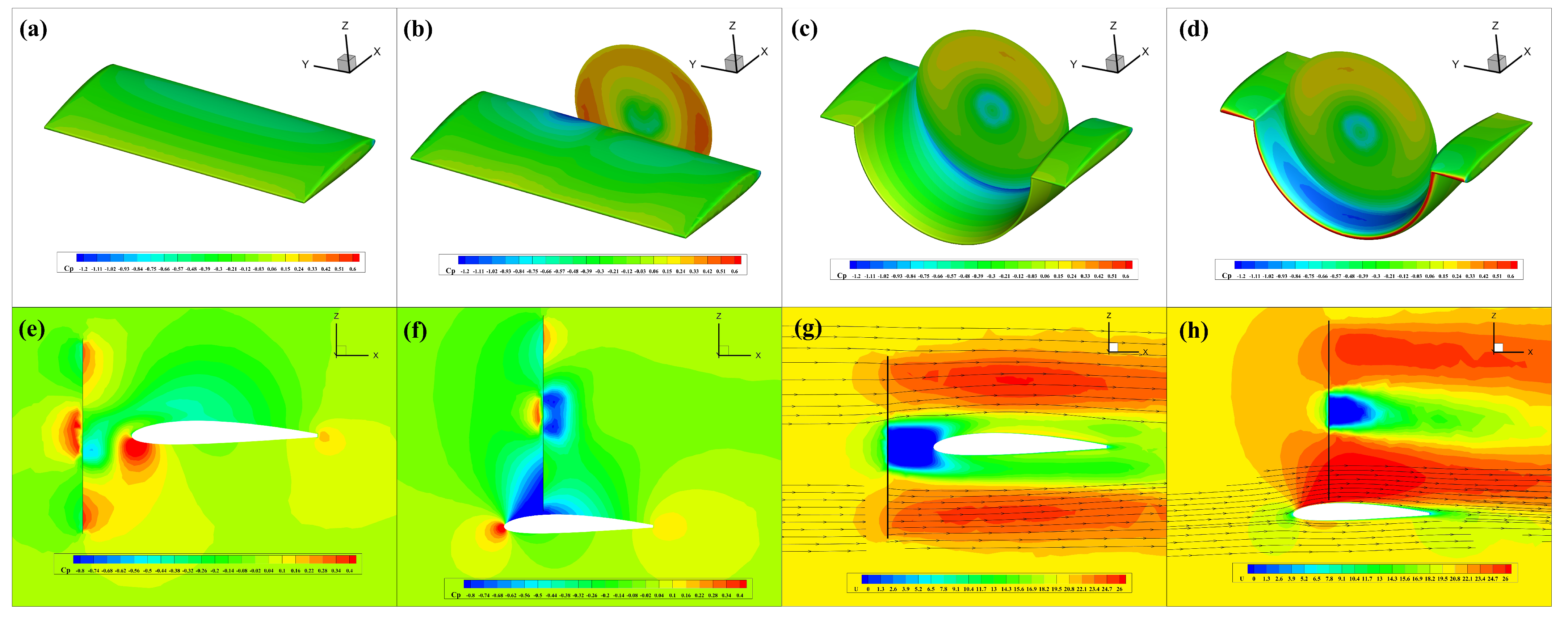
27] is employed for aerodynamic simulation. First, a comparative analysis was conducted among the clean wing, the straight wing equipped with a forward-mounted propeller, and the channel wing. Findings indicate that the channel wing offers notable enhancements in both lift and lift-to-drag ratio. Building on this, this paper further examines how the aerodynamic performance of the channel wing is influenced by the propeller-to-wing spacing, the propeller’s vertical position, and different propeller diameters under the same thrust. A simple experimental platform was then designed and constructed to verify the accuracy of the aerodynamic simulation results. Finally, this paper designs a tandem-wing aircraft with a lifting fuselage and compares two configurations: “forward propeller” and “channel wing”. The numerical simulation results for both configurations were compared, revealing that the drone with “channel wing” configuration offers enhanced lift performance along with a higher L/D efficiency than the “forward propeller” configuration, making it more suitable for STOL.
2. Actuator Disk Model
The channel wing configuration offers an enhanced lift capacity along with superior lift-to-drag performance, making it suitable for the STOL of UAVs. When conducting aerodynamic simulation calculations for the channel wing, it is necessary to simulate the working state of the propeller, and unsteady numerical calculation methods are usually adopted. Unsteady methods require a large amount of computing resources and take a long time at the same time. In order to improve the computing efficiency and reduce the use of computing resources and computing time, this paper adopts the actuator disk model and employs an actuator disk in place of the physical propeller. This method can transform the original transient calculation into a steady-state calculation and reduce the calculation duration.
The actuator disk model achieves an effective simulation of the propeller slipstream by setting a zero-thickness virtual boundary (the actuator disk) in the flow field and adding pressure incremental loads and rotational momentum incremental loads on the actuator disk. At a radius
r from the propeller axis, the infinitesimal thrust and torque components originate from pressure gradients and angular momentum changes across the actuator disk. These can be expressed as
The blade element located at a radial distance
r is characterized by the lift coefficient
, drag coefficient
, and chord length
c. The parameters
,
, and
W correspond to the local air density, the induced angle of attack, and the resultant relative velocity of the blade element. The airflow velocity upstream of the propeller is described in cylindrical coordinates as (
). The velocity field comprises three components, corresponding to their respective directions:
(radial),
(tangential), and
(axial). The rotational speed of the propeller is given by
. Based on these definitions, the expressions for the induced angle of attack and resultant velocity are formulated as follows:
The steady-state CFD analyses were performed by solving the RANS equations on unstructured grids. In this study, the upstream side of the actuator disk is defined as the outflow boundary, whereas the downstream side serves as the inflow boundary. Meanwhile, several parameters are set, including the blade count, radius, chord length, hub width, blade pitch angle, twist angle, and rotational velocity. In addition, aerodynamic coefficients of the propeller blades across a range of angles of attack are acquired for simulation input.
A comparison with experimental data was conducted to verify the accuracy of the actuator disk model predictions. The propeller under consideration features a two-blade configuration, incorporating a 0.381 m radius at the tip and the inner radius corresponding to the hub equals to 20% of the tip radius. The blades adopt an airfoil based on the Clark Y profile. Two test cases were identified for verification, drawing upon propeller performance data from the existing literature [
28]. The experimental condition included an inflow velocity of 30 m/s. In Case 1, the propeller rotated at 2420 rpm, while in Case 2, it operated at 3200 rpm. The simulation results obtained based on the actuator disk model are compared against the experimental measurements, as presented in
Table 1. The computed thrust and torque values exhibit a relative error within 5% of the experimental measurements, confirming the reliability of the actuator disk model.
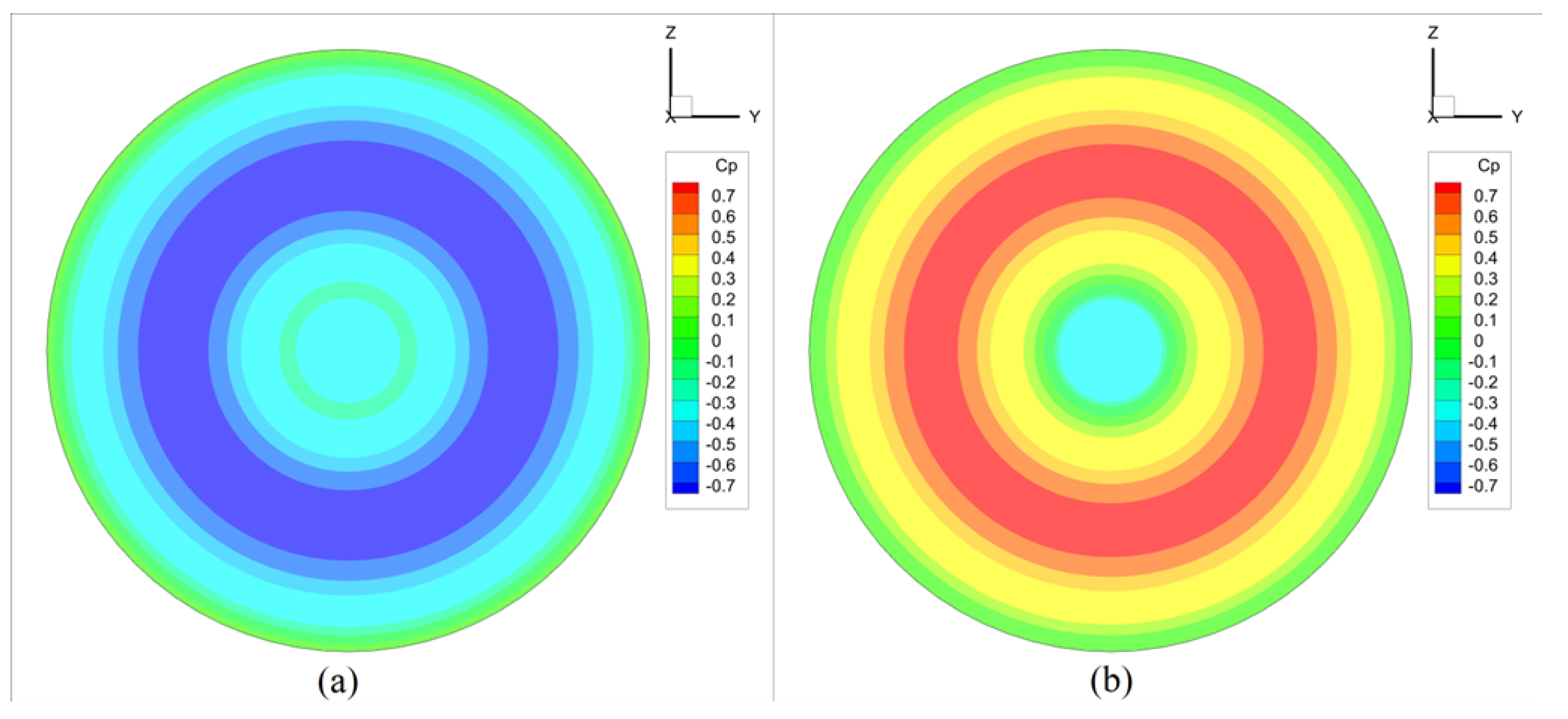
Figure 1 shows the pressure distribution across the actuator disk, highlighting the flow conditions upstream and downstream. Due to the contraction effect induced by the propeller’s rotation, the upstream pressure decreases, whereas a notable pressure rise is observed downstream. A discontinuity exists between the pressures on either side of the disk, aligning with the predictions by the theory of momentum conservation. A net pressure gain across the actuator disk gives rise to the generated thrust.
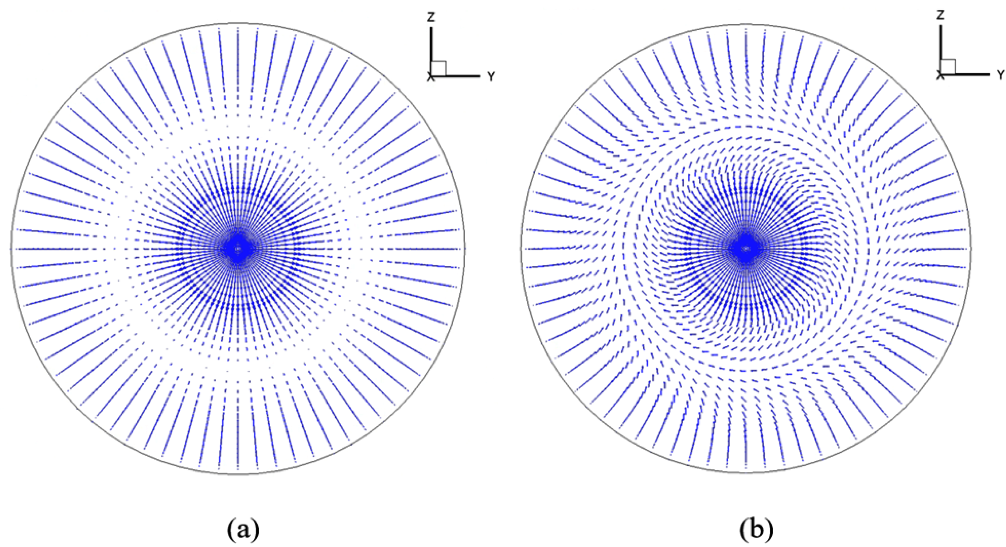
The velocity vector representation before and after the disk is visualized in
Figure 2. The upstream flow exhibits no apparent circumferential velocity, whereas a distinct swirl appears in the downstream region. This observation is consistent with the expected aerodynamic behavior, thereby supporting the validity of the actuator disk model.
The results confirm that the actuator disk model used herein effectively mirrors the aerodynamic response of the real propeller, making it a reliable approach for supporting the subsequent numerical simulations of the channel wing.
4. Key Parameters Governing Channel Wing Aerodynamics
The channel wing configuration can increase and reduce , offering advantages in the field of STOL for UAVs. To explore the detailed characteristics of the channel wing, this paper further examines the factors affecting the channel wing’s aerodynamic properties.
4.1. Influence of Propeller-to-Channel Wing Clearance
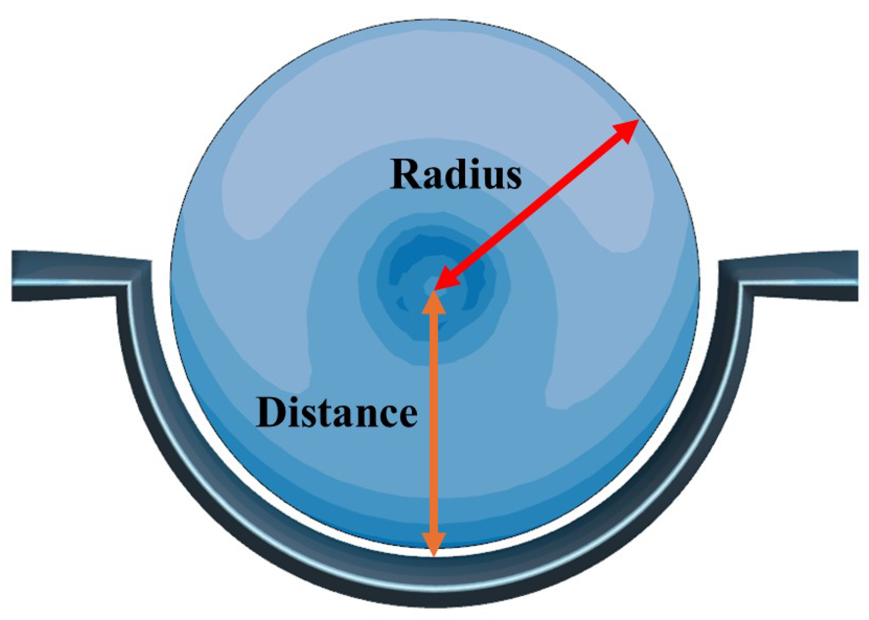
Motivated by studies on the effect of clearance on culvert aerodynamics, this paper initially explores how the spacing between the propeller and the channel wing influences the aerodynamic performance of the channel wing configuration. In
Figure 6, the vertical distance from the propeller center to the upper surface of the channel wing is defined as
D, and the radius of the propeller is defined as
R. The clearance
i can be obtained as
, and the ratio
is defined as
I =
i/
R. The propeller diameter is 250 mm, the rotational speed is 6000 rpm, and the wingspan is 400 mm. Six different clearance values are selected for analysis, with the specific values provided in
Table 3. In this set of examples, the propeller remains unchanged, and the clearance is varied by adjusting the size of the curved wing segment of the channel wing.
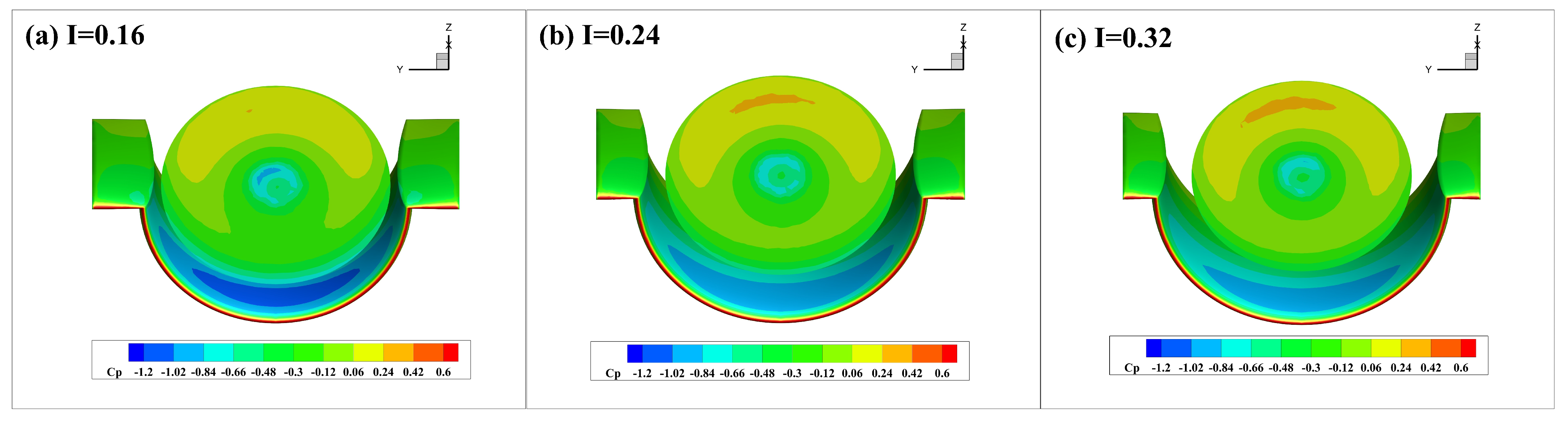
After the calculations are completed, the results are post-processed to generate the pressure distribution diagram, as shown in
Figure 7. As the clearance increases, the surface color becomes lighter, indicating a region of lower pressure. Therefore, it can be concluded that an increase in channel wing lift is induced by a reduction in the propeller–wing clearance. When integrating the channel wing into UAVs, maintaining a minimal clearance is essential.
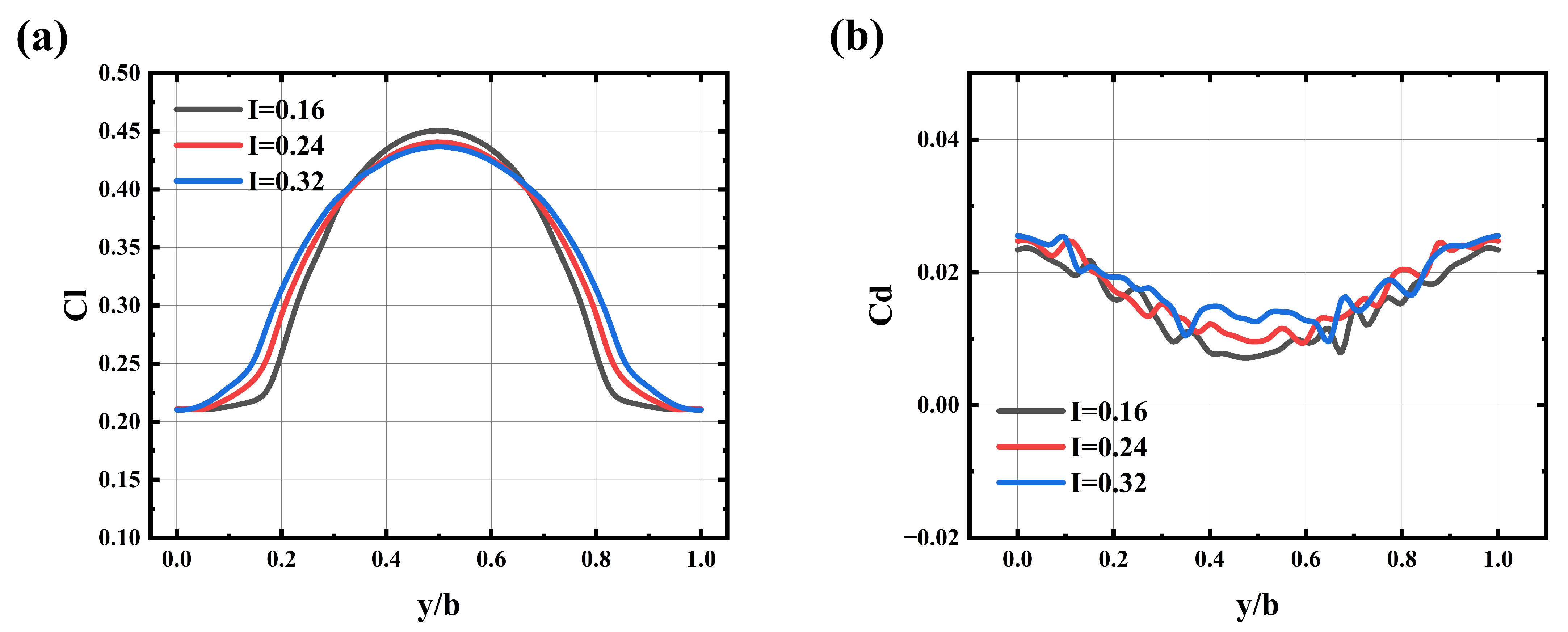
Figure 8 illustrates aerodynamic coefficient distribution along the wingspan of the channel wing.
Figure 8a is the lift coefficient profile. Notably, the propeller induces a pressure reduction upstream of the actuator disk, resulting in an enhanced lift over the curved section of the channel wing. Moreover, as the clearance decreases, a corresponding increase in the magnitude of the negative pressure peak on the channel wing is observed. Consequently, the lift coefficient exhibits an increasing trend with decreasing clearance.
Figure 8b presents the distribution of the drag coefficient. Drag coefficient is relatively high at the straight wing sections near both wingtips, while it gradually decreases towards the curved central section. This observation further confirms the drag-reduction advantage of the channel wing compared to a conventional straight wing configuration. This phenomenon occurs because the propeller induces a reduction in airflow pressure along the upstream flow direction ahead of the propeller disk, causing a pressure drop at the front portion of the channel wing’s curved segment. As a result, the drag caused by pressure differentials on the channel wing is diminished.
4.2. Influence of Propeller Position Above the Channel Wing
For the channel wing configuration, a distinct low-pressure area develops between the leading edge and the propeller location. This demonstrates that the propeller’s position along the chord has a direct impact on the aerodynamic behavior of the system. Therefore, this paper analyzes the aerodynamic implications of varying the propeller’s location above the channel wing.
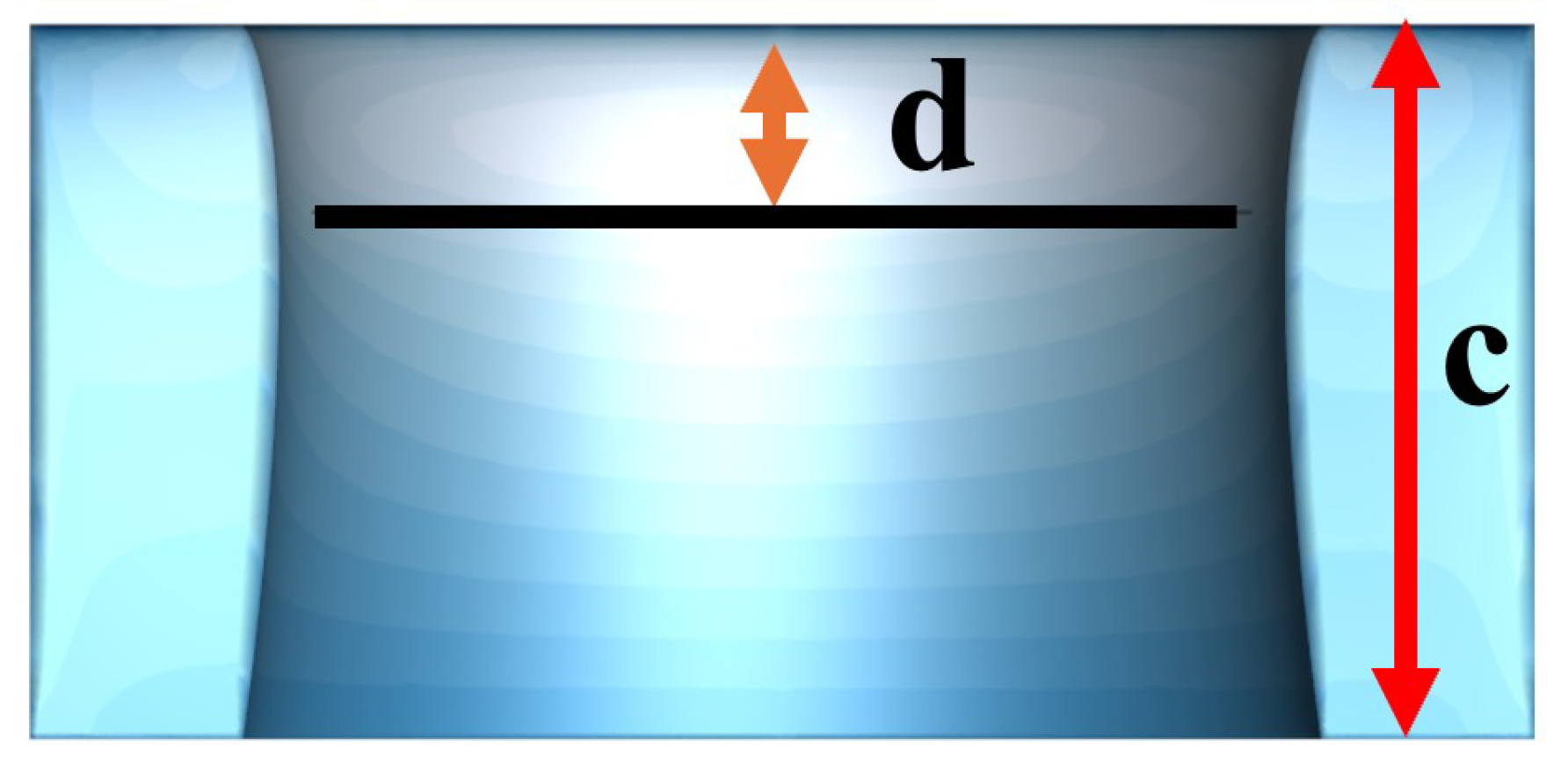
Figure 9 demonstrates that the wing’s chordal length is
(where
= 200 mm), and the distance from the leading edge of the wing to the propeller along the chord is
. The ratio
Q =
d/
c is defined. The propeller diameter is 250 mm, the rotational speed is 6000 rpm, and the wingspan is 400 mm. Twelve cases were selected for simulation calculations, with the specific numerical conditions provided in
Table 4. In these cases, the channel wing configuration is held constant while the propeller mounting position is varied along the chordwise direction of the wing.
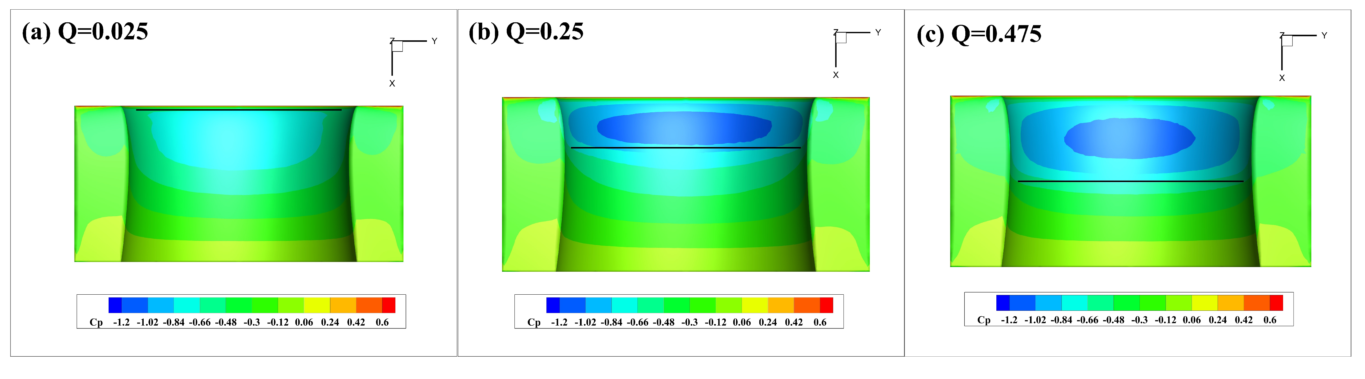
Figure 10 presents the resulting pressure field for the three cases (Q = 0.025, 0.25, 0.475). As the distance from the channel wing’s leading edge to the propeller increases, the negative pressure area on the upper surface of the wing gradually expands. However, the color change of the negative pressure varies. When
changes from 0.025 to 0.25, the negative pressure color becomes darker, indicating that the minimum negative pressure is in this region, resulting in the best lift effect. As
varies from 0.25 to 1, the negative pressure region expands while the color intensity gradually decreases, indicating that although the overall influence of this area becomes more pronounced, the lift effect per unit area diminishes.
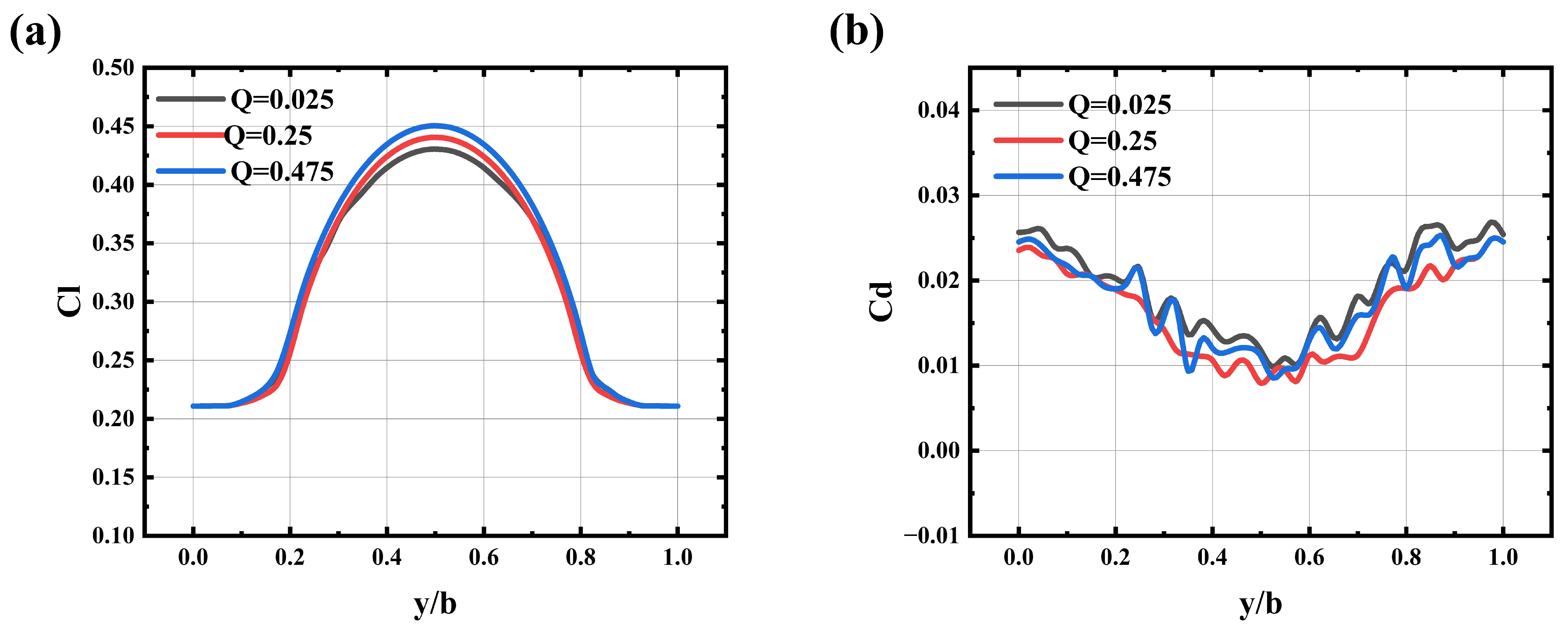
The distribution of lift and drag coefficients, as shown in
Figure 11, indicate that as the propeller installation position shifts rearward along the wing’s tangential direction, the lift enhancement effect on the curved section of the channel wing gradually increases. Regarding the drag coefficient distribution, the drag experienced by the curved wing section remains consistently lower than that of the straight wing sections.
Overall, as the distance increases, the area on the wing’s upper surface influenced by the wall attachment effect expands, thereby enhancing the lift performance. However, as the propeller moves closer to the trailing edge, a noticeable decline in the lift coefficient is observed. When utilizing the channel wing configuration for STOL applications, the propeller can be optimally installed further from the leading edge. Conversely, if maximizing the lift-to-drag ratio is the primary objective, positioning the propeller closer to the wing’s leading edge is preferable.
4.3. The Influence of Different Propeller Diameters with the Same Thrust
To further study the effect of different propeller diameters, it is necessary to maintain the same thrust. Under this condition, when the diameter of the propeller changes, the speed must adjust accordingly. This paper presents seven different propeller diameters, with the specific values provided in
Table 5. As shown in
Figure 12, to maintain the same clearance, the radius of the channel wing must also change when the diameter of the propeller changes. Additionally, to ensure the wingspan remains constant, the straight wing segments on both sides of the wing must also adjust when the radius of the curved wing changes.
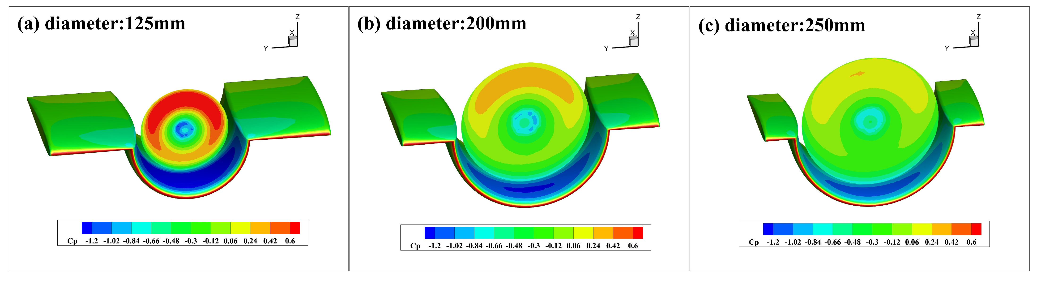
The pressure distribution diagrams for the three cases (diameters are 125, 200, and 250 mm) are shown in
Figure 13 to further analyze the underlying reasons. Under the condition of the same thrust, as the propeller diameter decreases, a darker shade in the negative pressure region on the wing’s upper surface indicates an intensified wall-attachment effect. However, the negative pressure area becomes smaller, leading to an overall reduction in the improvement of lift.
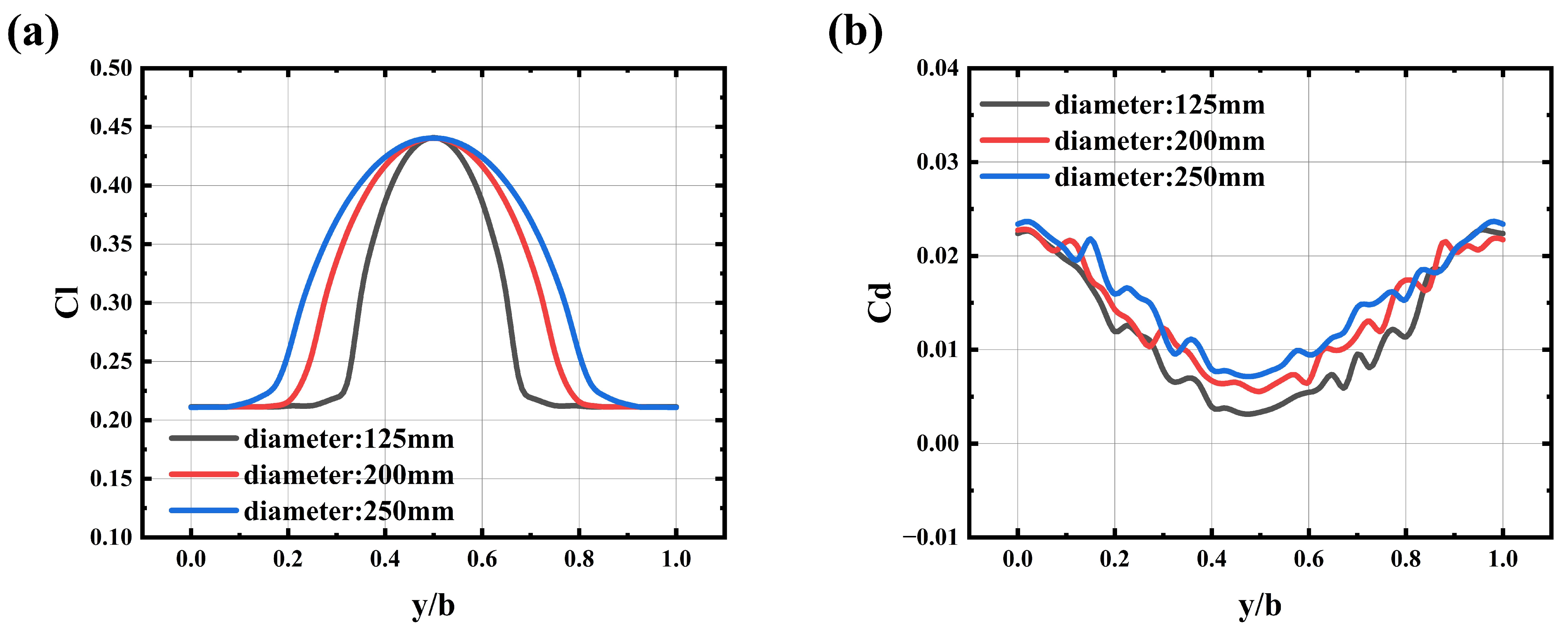
A decrease in propeller diameter corresponds to a reduction in the wing area of the curved section of the channel wing. Since the curved section generates higher lift compared to the straight section, this reduction leads to a smaller proportion of the wingspan contributing to lift augmentation. As illustrated in
Figure 14a, the total lift generated by the channel wing is reduced accordingly.
Figure 14b shows that the channel wing experiences a continuous drop in
in response to the decrease in propeller diameter. To maintain the same thrust with a smaller diameter propeller, the rotational speed must increase. Elevated rotational speeds further reduce the airflow pressure upstream at the leading edge of the curved wing section, thereby decreasing the pressure difference-induced drag on the wing. This implies that, for a given thrust, employing a smaller diameter propeller can effectively reduce drag.
The results show that when the thrust is the same, the channel wing with a small-sized propeller has a better L/D, but a lower lift coefficient.
4.4. Overall Performance
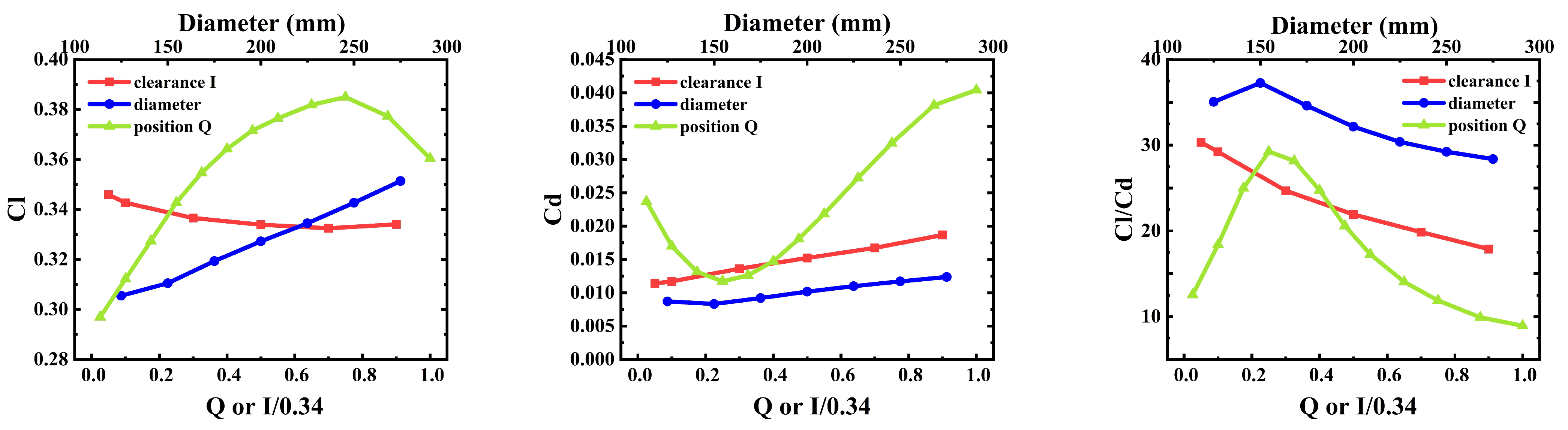
This paper first analyzes three key factors influencing the channel wing aerodynamic efficiency individually.
Figure 15 provides a comprehensive summary of the aerodynamic coefficients of the channel wing under variations in three key parameters. The results clearly indicate that reducing the clearance between the propeller and the channel wing leads to an increase in the lift coefficient, a reduction in the drag coefficient, and thus, an enhancement in the lift-to-drag ratio. Furthermore, under constant thrust conditions, enlarging the propeller diameter raises both the lift and drag coefficients; however, the overall lift-to-drag ratio tends to decline. Furthermore, with the rearward shift in the propeller along the chordwise direction of the wing, the lift coefficient initially rises and then falls, whereas the drag coefficient shows an inverse pattern—first decreasing and then increasing. Ultimately, the L/D follows a similar trend of initially increasing and subsequently decreasing.
Furthermore, a comparative analysis revealed that the channel wing lift coefficient exhibits low sensitivity to the clearance between the propeller and the wing. In contrast, both the propeller diameter and its installation position along the chordwise direction exert a more significant influence on the lift coefficient. Regarding the , the channel wing demonstrates notable sensitivity to the propeller’s installation position, while showing relatively low sensitivity to variations in clearance and propeller diameter. Consequently, overall, changes in propeller diameter have a comparatively minor effect on the lift-to-drag ratio of the channel wing relative to the other two parameters.
5. Ground Experimental Verification
The adoption of the channel wing structure contributes to higher lift coefficients and more favorable lift-to-drag ratios for UAVs. To further validate the simulation results above, a simple ground experimental platform was constructed to test channel wing aerodynamic efficiency.
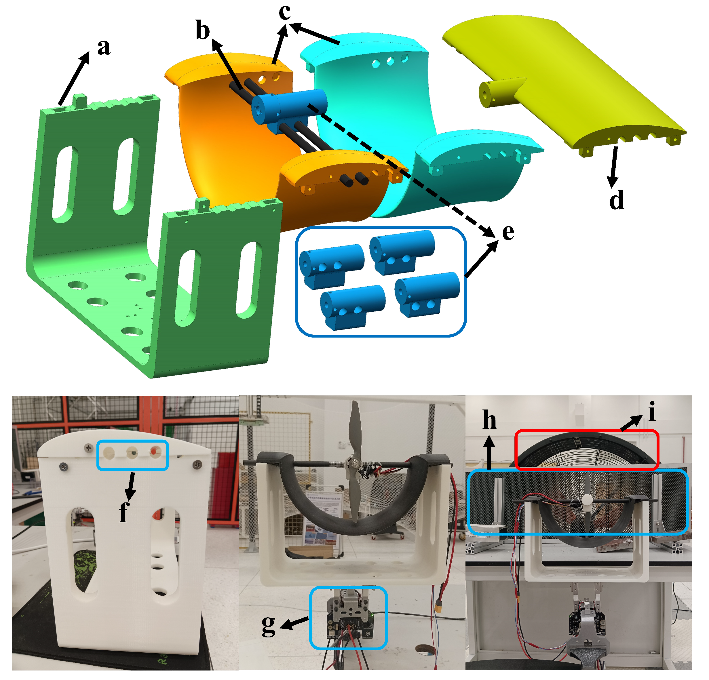
Figure 16 illustrates the basic setup of the experimental platform, which primarily includes the following components:
a: Pedestal, primarily used to support the straight wing and channel wings;
b: Two carbon tubes, used to assemble the motor and wings;
c: Two channel wings, differing only in the aperture position of the carbon tube—all other aspects are the same;
d: Straight wing, used for comparison experiments with the channel wing;
e: Motor bases, differing only in the aperture position of the carbon tube and used to adjust the clearance—all other aspects are the same;
f: Aperture, through which the carbon tube passes—used to adjust the motor location along the chord on the upper side of the channel wing;
g: Test bench, containing a sensor that measures vertical force—the lift force is determined by changes in this force (the series 1585 thrust stand datasheet was produced by Tyto Robotics);
h: Honeycomb plate, with 7.5 mm apertures, designed to preserve the axial velocity in front of the fan, suppress the normal velocity, and ensure a uniform inflow condition;
i: Fan, which provides the incoming flow.
Both the straight wing and the channel wing feature a wingspan of 320 mm and a chord length of 150 mm, while the propeller diameter is set at 203.2 mm. During the test, the propeller rotational speed is maintained at 6558 rpm.
Typically, ground tests are conducted in the absence of incoming flow; however, during flight, drones experience a relative incoming airflow. For enhanced fidelity in modeling the aerodynamic features of the channel wing in a real flight environment, this paper uses an electric fan to generate incoming flow, which is then filtered through a honeycomb panel in front of the fan to create a uniform flow environment. In this experiment, two conditions—non-incoming and incoming flow—were tested.
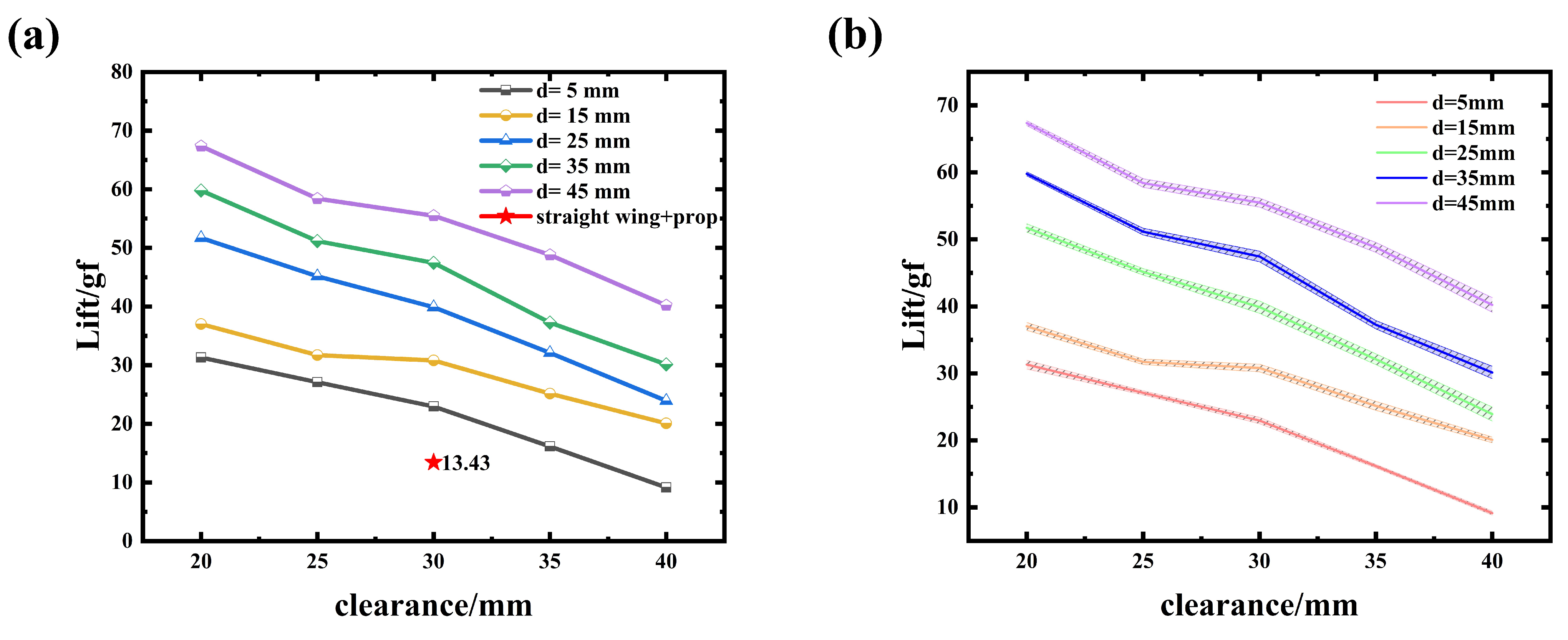
Figure 17 shows the test data results without incoming flow. The horizontal axis indicates the clearance
, while the vertical axis corresponds to the lift force. In the legend,
represents the chordwise distance between the propeller and the wing’s leading edge. For each clearance value, multiple datasets corresponding to different axial distances are presented. The red star denotes the test result for the straight wing equipped with a forward-mounted propeller. Overall, as the clearance increases, the lift force generated by the channel wing tends to decrease. Specifically, when
ranges from 5 to 45 mm, an increase in axial distance leads to a corresponding rise in lift. In the absence of incoming flow, the channel wing can produce a certain lift force, while the straight wing with the forward propeller generates only a weak lift force. In the absence of incoming flow, the test conditions remained relatively stable, resulting in a small measurement error. The error magnitude was observed to range between 0.3 and 1.1 gf, as illustrated in
Figure 17b.
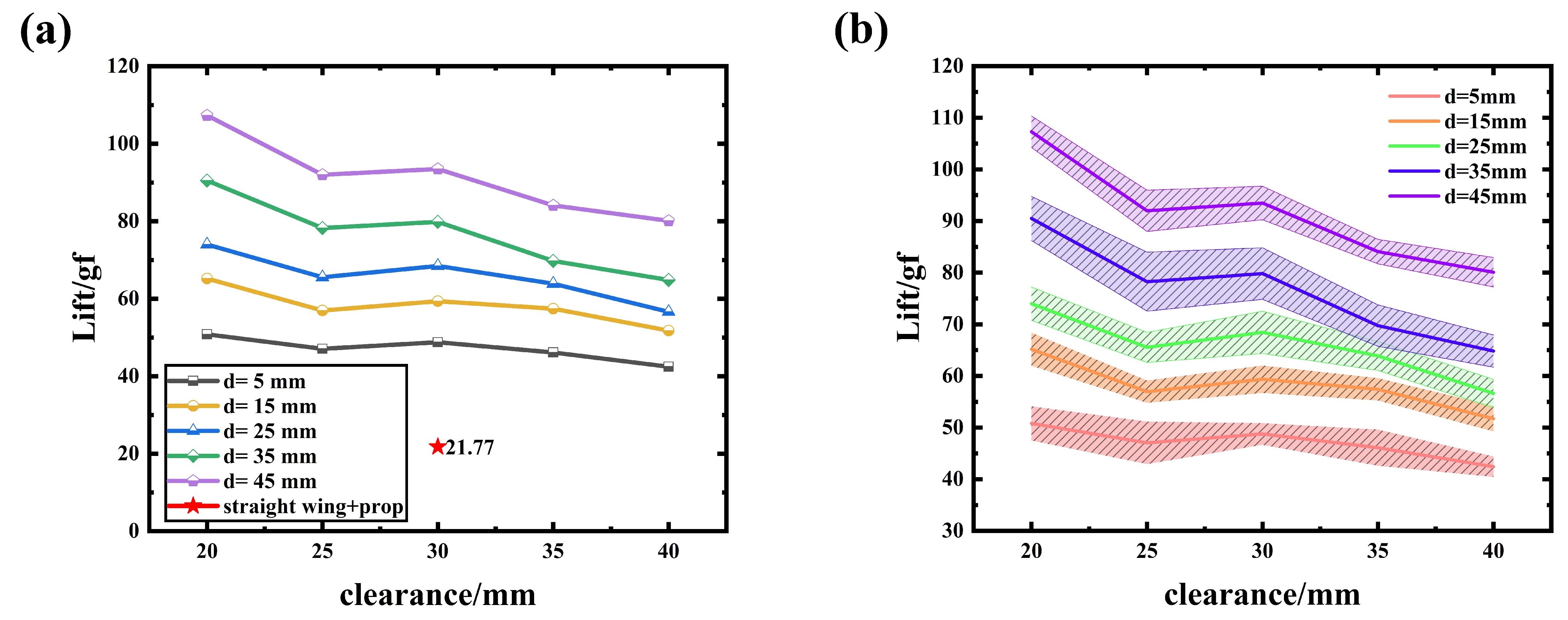
The results of the channel wing test data with incoming flow are shown in
Figure 18. The incoming flow speed through the honeycomb panel is 3.7 m/s. Under the condition of incoming flow, as the clearance
increases, the lift generated by the channel wing does not change significantly when the distance
is small. However, as the distance increases, the lift of the channel wing decreases with the increase in clearance. When the clearance remains the same, in the range of 5 to 45 mm, the lift of the channel wing increases with the increasing distance between the propeller and the leading edge of the wing. Similarly, with incoming flow, the lift generated by the channel wing is still greater than that of the straight wing with the forward propeller. In the presence of incoming flow, additional disturbances arise during testing, leading to increased measurement errors. As shown in
Figure 18b, the error magnitude ranges from 2 to 6 gf.
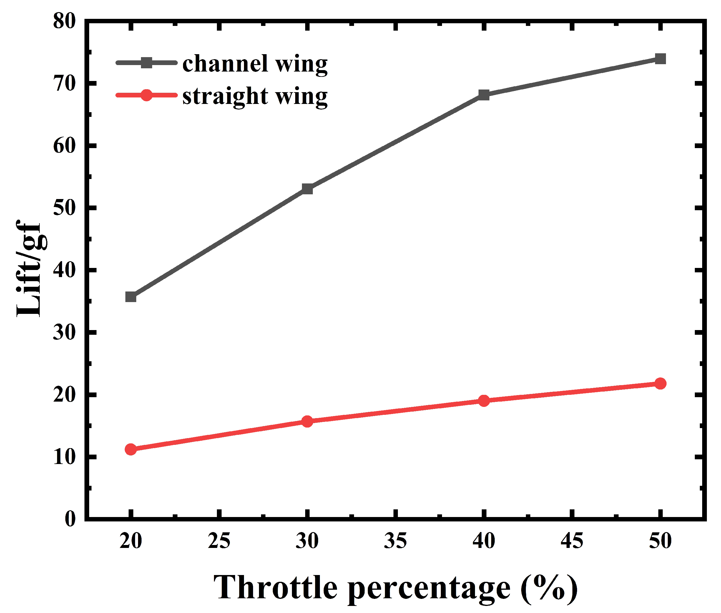
Figure 19 depicts the lift variation of both the channel wing and straight wing under different thrust levels induced by throttle settings. In the channel wing configuration, the clearance
is fixed at 20 mm, and the propeller is mounted 25 mm from the reference point. As the throttle increases, the channel wing demonstrates a significant lift enhancement, while the lift generated by the straight wing remains largely unchanged.
The experimental findings support the computed results presented above: decreasing the clearance enhances the lift produced by the wing. Within the region from the leading edge to the quarter-chord point, a greater distance between the propeller and the leading edge corresponds to a higher lift force in the channel wing configuration. Furthermore, the test results reveal that the channel wing is capable of generating lift even in the absence of freestream flow. Under low incoming flow conditions, it outperforms the straight wing with a forward-mounted propeller in terms of lift generation.
6. Comparison of Aircraft Performance
Compared to the wing with a forward propeller, the channel wing has a higher L/D, which enhances the aerodynamic performance of the drone when applied to the aircraft. To further explore the aerodynamic advantages of the channel wing, this paper presents a simple design of a tandem-wing aircraft with a lifting fuselage, where the channel wing is applied to the front wing of the tandem configuration, as visualized in
Figure 20b.
Figure 20a shows a comparison of the prototype, where only the wing with forward propellers is replaced by channel wings.
Table 6 lists the fundamental design parameters of the aircraft.
To compare the aerodynamic efficiency of the channel wing and the wing with a forward propeller applied to the aircraft, the two UAVs were simulated, and the results are shown in
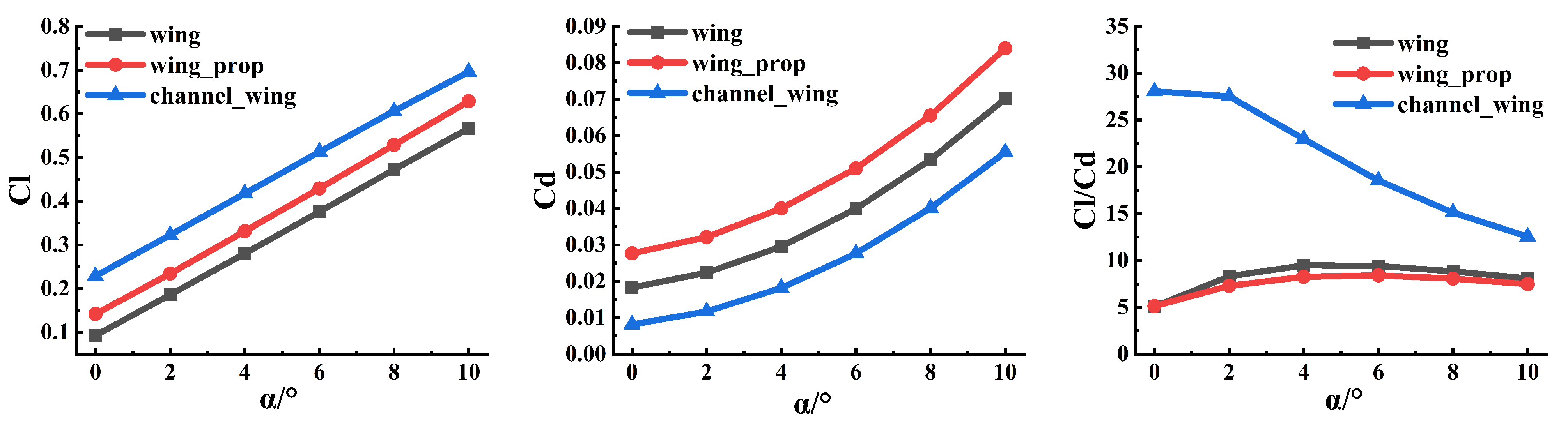
Figure 21. The UAV with the channel wing has a steeper lift curve than the UAV with the forward propeller, resulting in a higher overall lift coefficient. Additionally, in terms of drag coefficient, the UAV with the channel wing exhibits significantly lower drag. As a result, the UAV with the channel wing has a better lift-to-drag ratio, with a maximum value of approximately 18.6, while the corresponding UAV with the forward propeller has a maximum lift-to-drag ratio of only about 9.4. In terms of maximum lift-to-drag ratio, the UAV with the channel wing achieves approximately twice the value of the UAV with the forward propeller. Clearly, the application of channel wings significantly enhances the overall aerodynamic performance of UAVs.
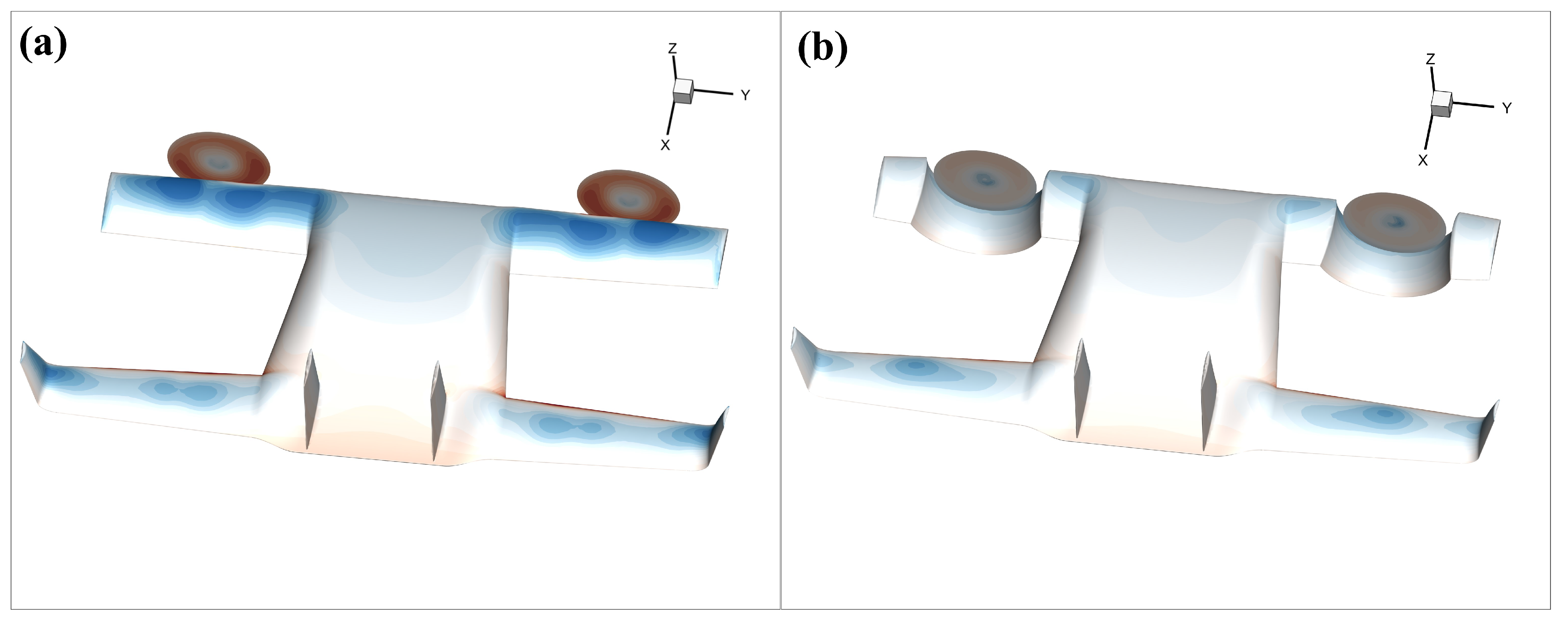
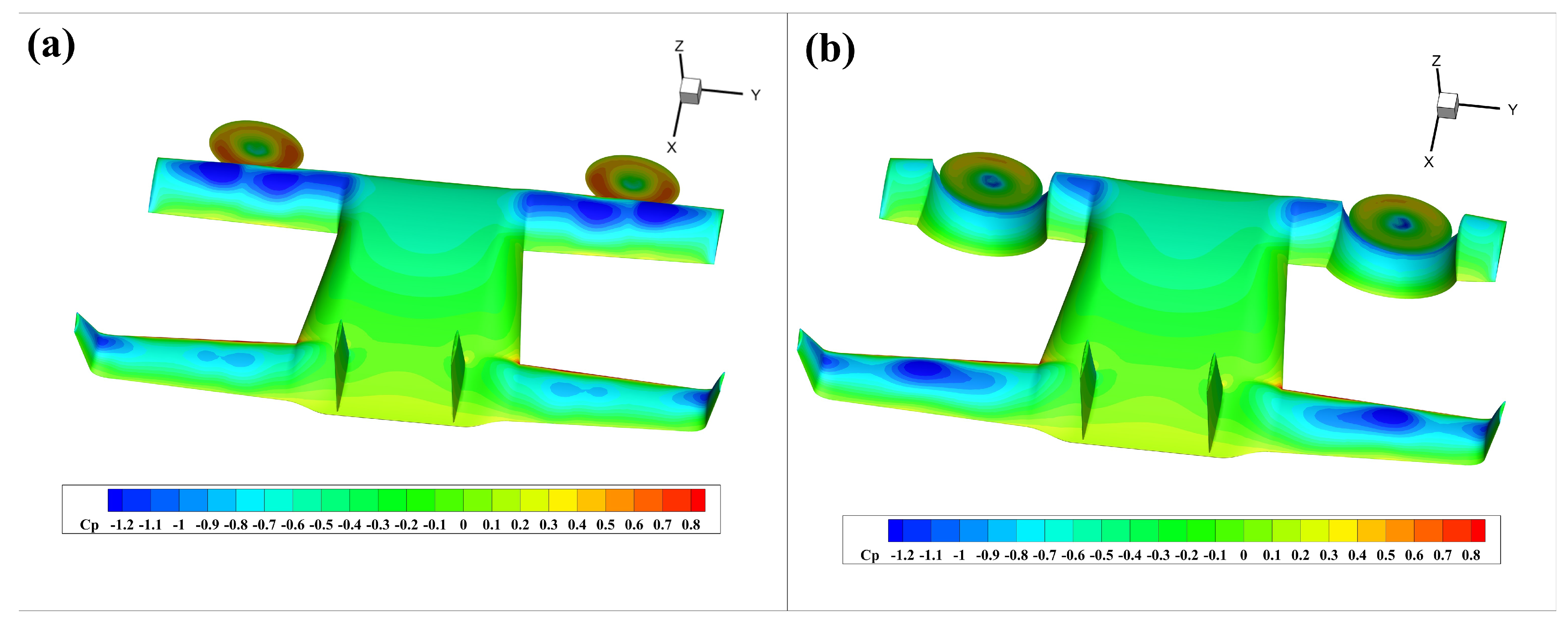
Figure 22 presents the pressure coefficient distribution for a comparative analysis of the aerodynamic behavior between the two drones. As observed in
Figure 22a, there is a distinct negative pressure zone on the upper surface of the front wing with the forward propeller, which effectively utilizes the slipstream effect of the propeller to enhance the wing’s lift. Simultaneously, owing to the wing’s three-dimensional characteristics, the slipstream exerts influence along the full span of the leading edge. However, only a minor aerodynamic effect from the forward propeller slipstream is observed on the rear wing. According to
Figure 22b, the channel wing predominantly impacts the curved segment of the front wing, with relatively little influence from the straight wing on either side. A negative pressure zone appears in the inner straight wing segment, while the outer straight wing segment is almost unaffected. Compared to the forward propeller configuration, a much stronger aerodynamic interaction is observed between the channel wing and the rear wing, with a large negative pressure area on the upper surface of the rear wing corresponding to the position of the propeller. The wake generated by the propeller travels over the front wing and continues unimpeded to the rear wing, creating a slipstream effect that increases the lift force on the rear wing.
Based on the above analysis, configuring the front wing of a tandem-wing UAV as a channel wing not only enhances its own aerodynamic efficiency through improved lift and reduced drag, but also enables the rear wing to benefit from the slipstream produced by the propeller wake, leading to a further increase in rear wing lift.
7. Conclusions
The channel wing configuration is characterized by high lift generation and an enhanced lift-to-drag ratio, rendering it well suited for the STOL operation in UAVs. To better apply its application in UAV systems, a thorough understanding of the channel wing configuration’s specific aerodynamic characteristics is essential. In this paper, the actuator disk model is employed to numerically investigate the aerodynamic performance of the channel wing. First, the advantages of the high L/D of the channel wing are analyzed by comparing it with the clean wing and the wing with a forward propeller configuration. Next, the effects of different clearances, leading edge distances, and propeller sizes on the aerodynamic performance of the channel wing are simulated. Simultaneously, a simple test platform was designed and constructed to perform a series of tests to validate our numerical results. Finally, a lifting-fuselage tandem-wing UAV incorporating a front-mounted channel wing was designed, and its performance was evaluated in comparison with a forward-propeller UAV configuration. The analysis results are as follows:
(1) The forward-mounted propeller on a straight wing increases the lift coefficient due to the slipstream effect but also causes a rise in drag. Conversely, the channel wing configuration enhances lift and reduces drag compared to the clean wing, resulting in improved aerodynamic efficiency.
(2) A reduced clearance between the propeller and the channel wing leads to a greater lift enhancement, thereby improving the lift-to-drag ratio. As the propeller mounted on the upper surface of the wing is positioned further from the leading edge, the lift coefficient increases. Under the same thrust condition, a larger propeller diameter generates more lift for the channel wing, but also increases resistance. Within a certain range, a smaller propeller diameter can achieve a better lift-to-drag ratio.
(3) Incorporating a channel wing into the front wing of a lifting-fuselage tandem-wing UAV enhances the front wing’s lift performance while simultaneously enabling the rear wing to harness the slipstream from the propeller wake, thereby further augmenting its lift. The channel wing configuration achieves a lift-to-drag ratio of approximately 18.6, nearly double the lift-to-drag ratio of the forward propeller configuration.


