
An Efficient SDOF Sweep Wing Morphing Technology for eVTOL-UAV and Experimental Realization


Abstract
1. Introduction
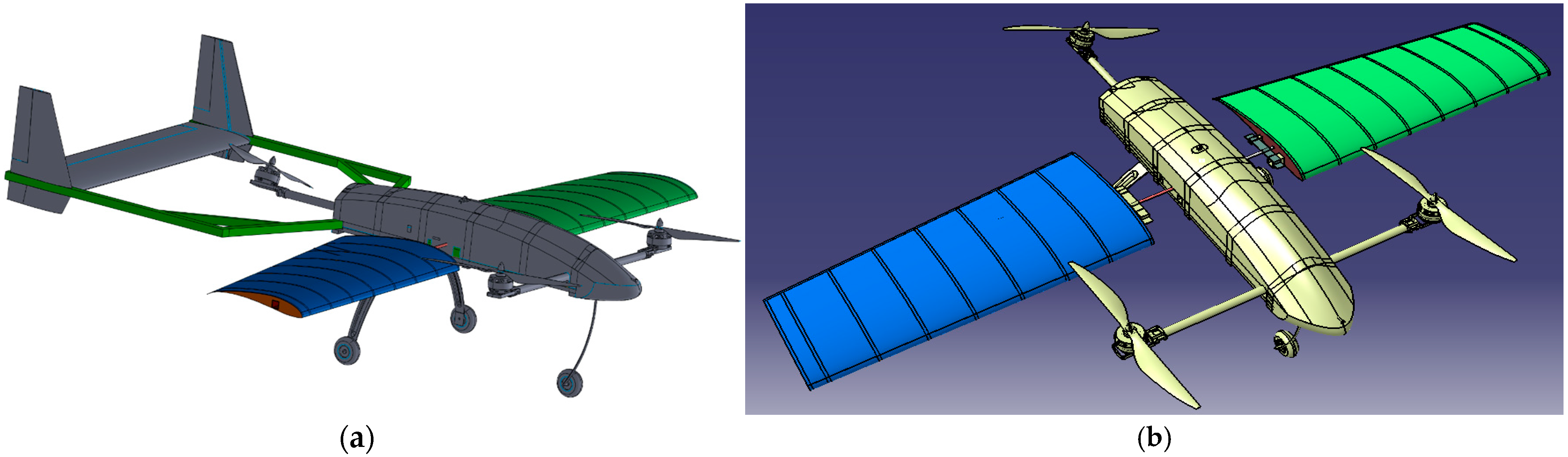
2. SDOF Morphing Wing Design and Integration
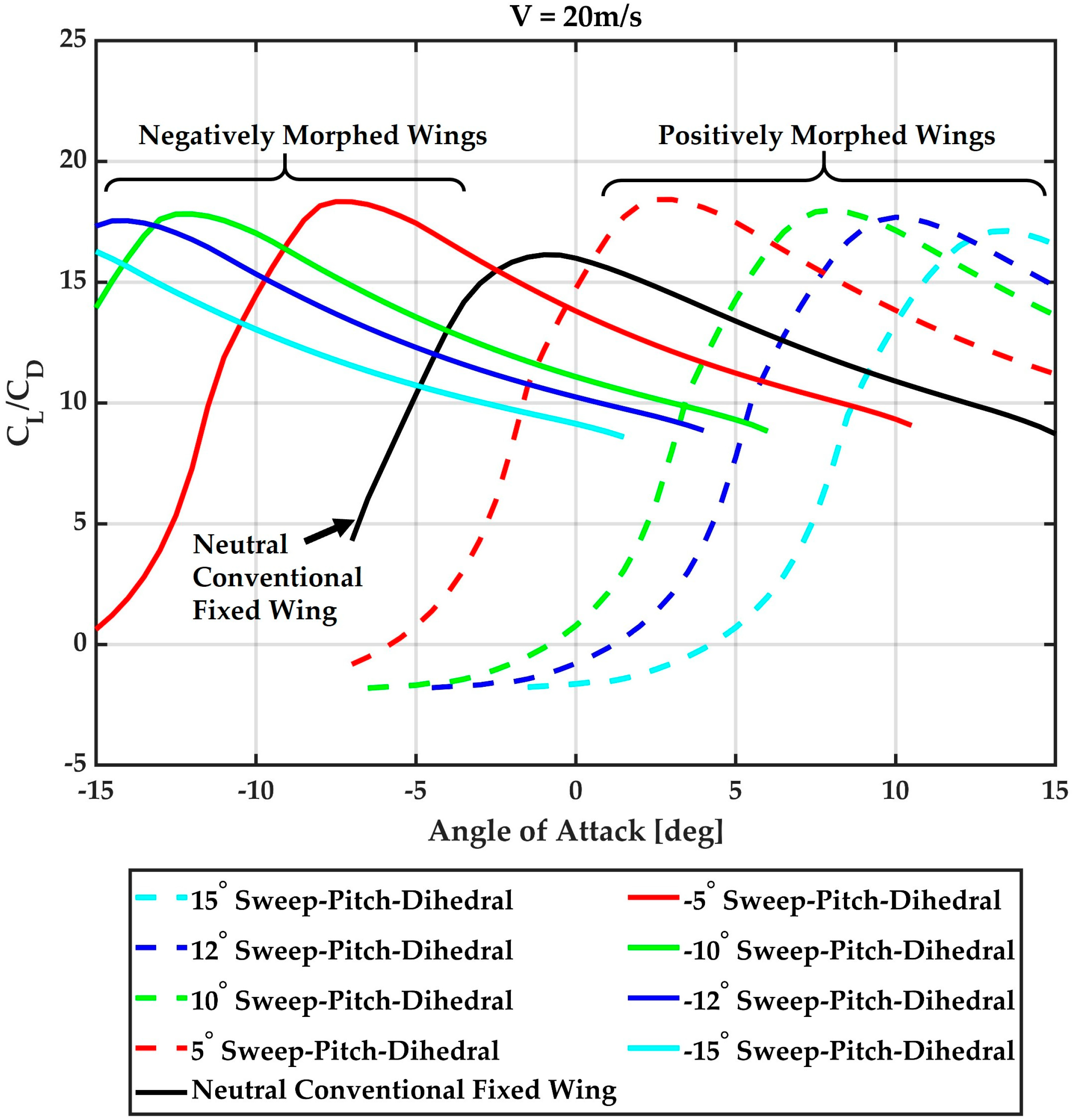
Aerodynamic Analysis of Wing
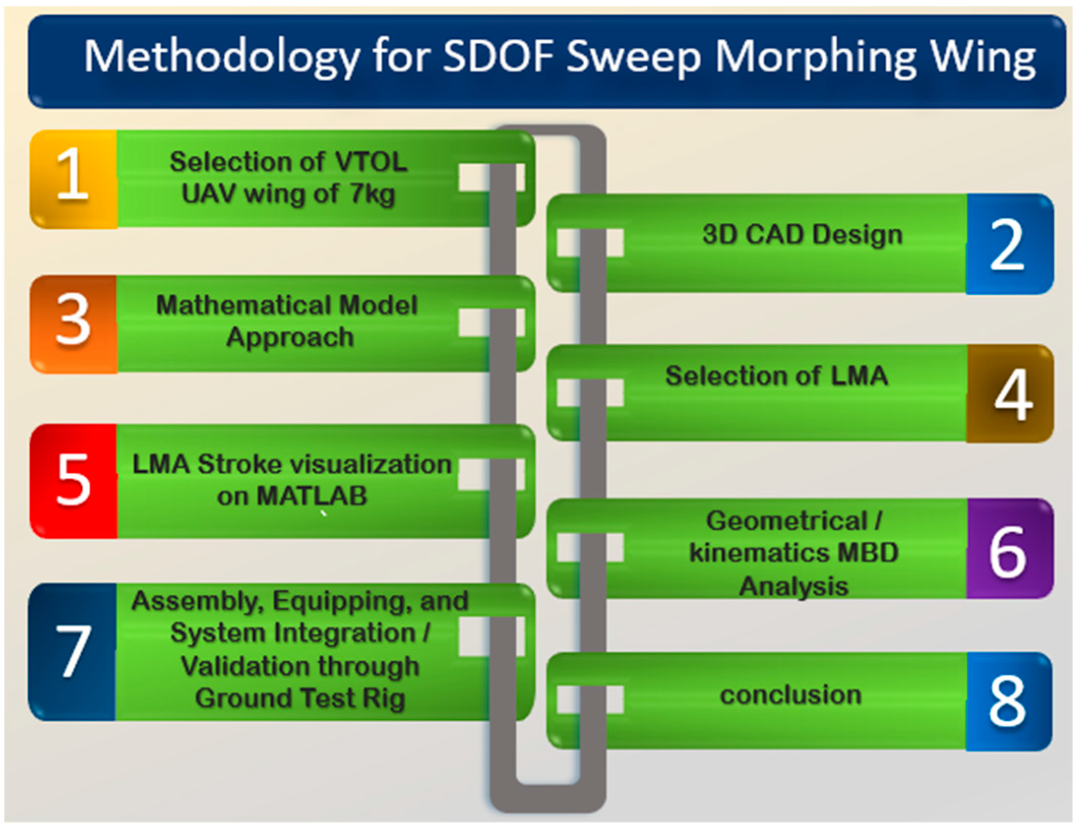
3. Methodology for SDOF Sweep Mathematical Model
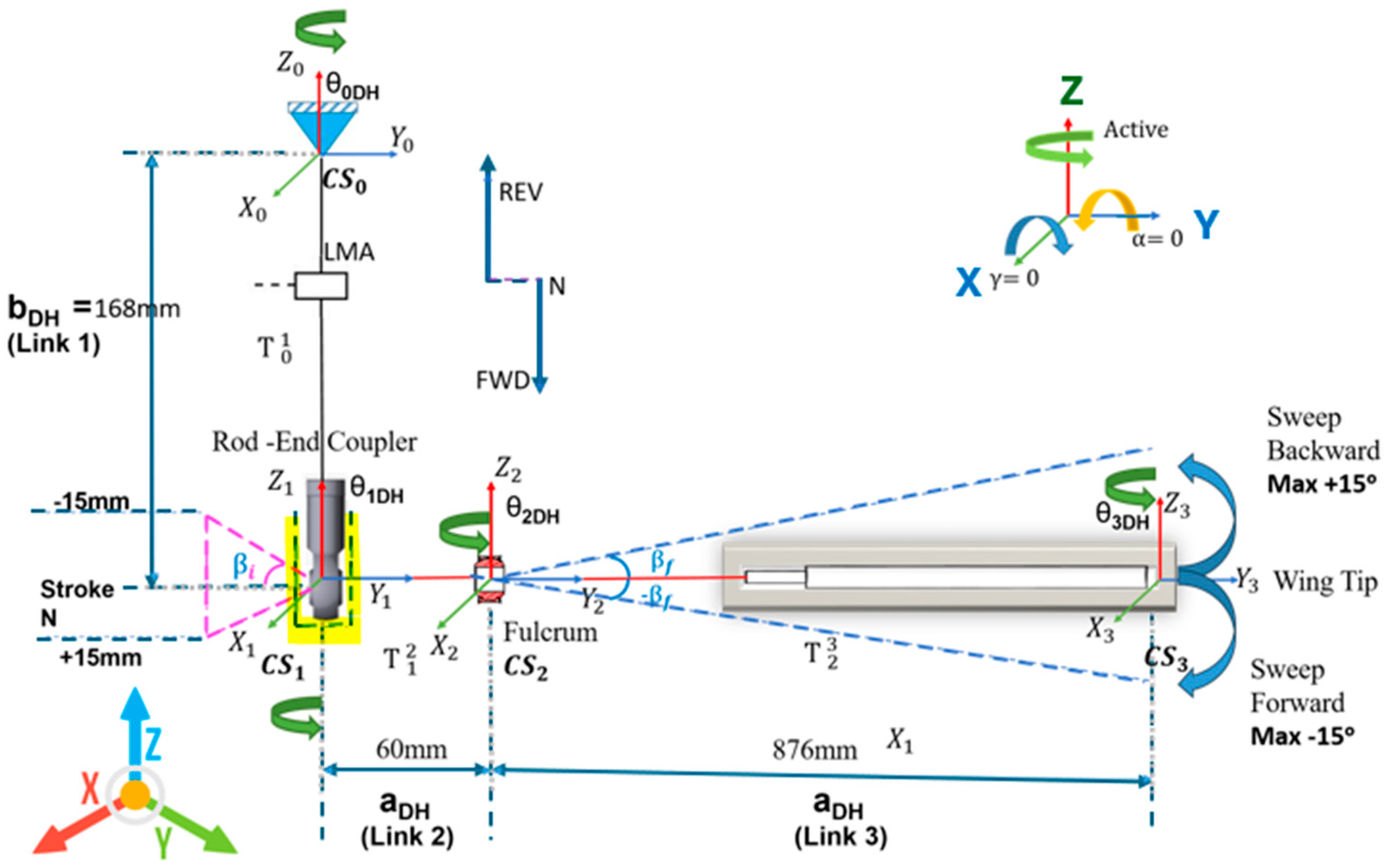
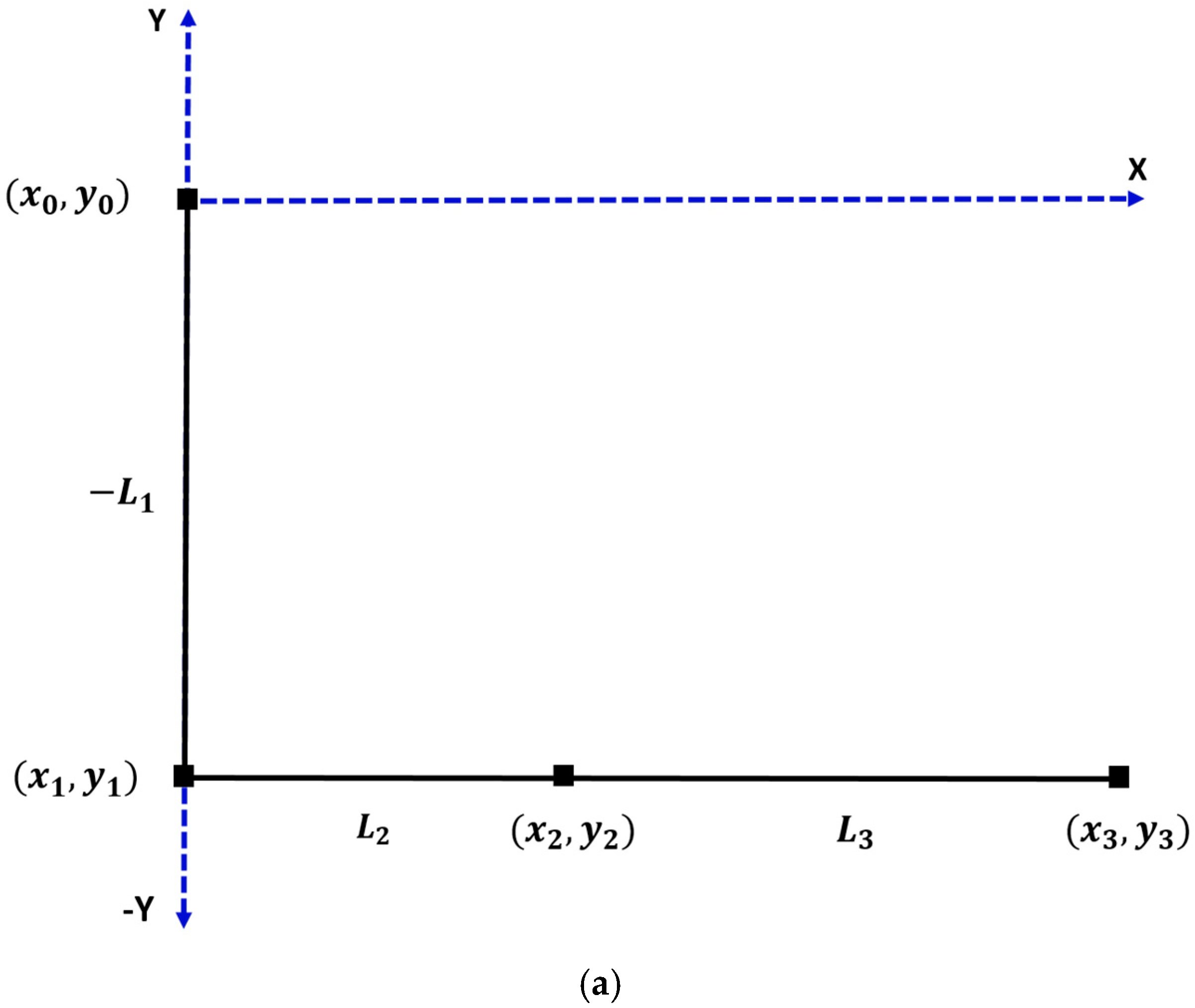
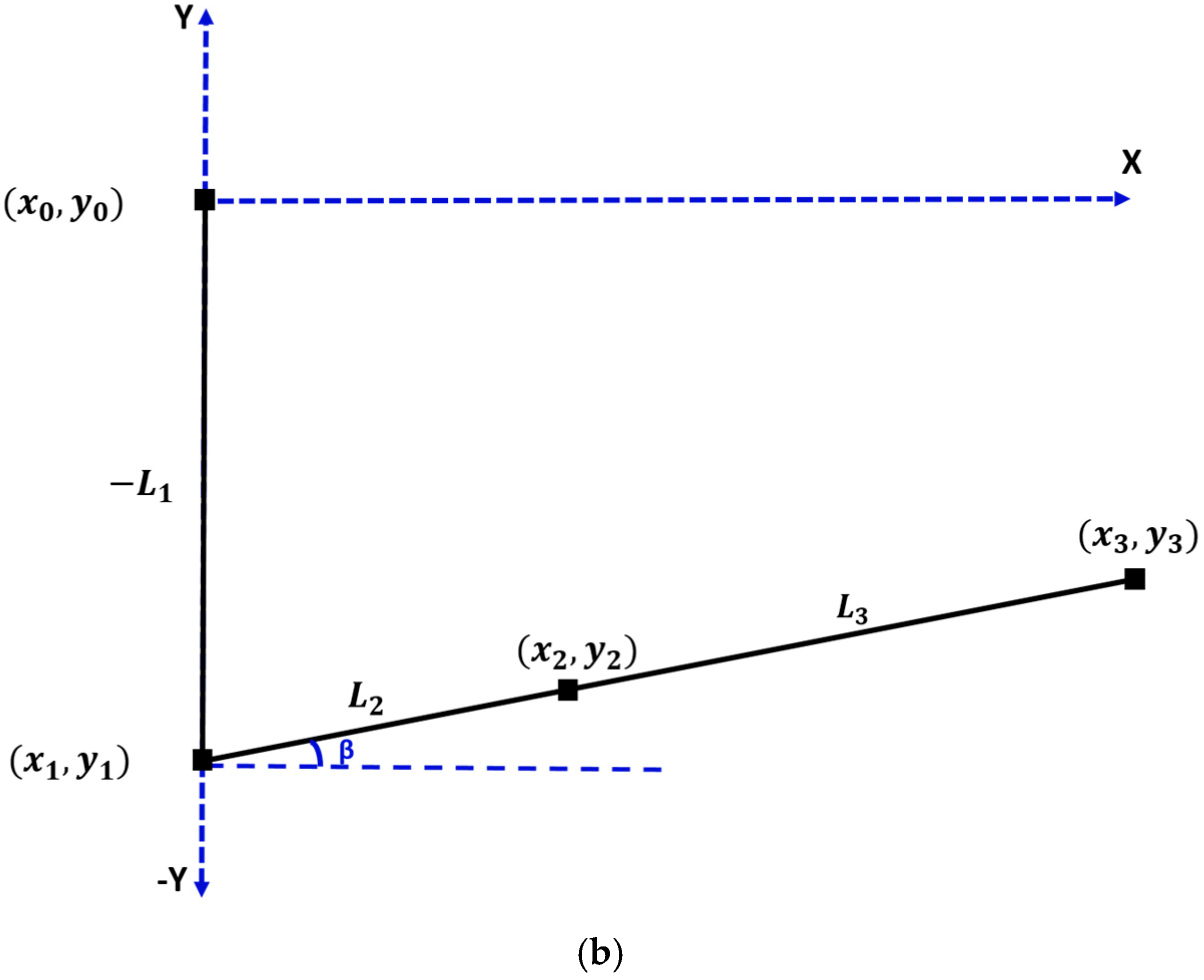
3.1. System Forward Kinematics Using D-H Convention
3.2. Rigid Body Equations of Motion for Single-Axis Sweep Morphing
- where x0, y0 = (0,0),
- H () represents the matrix containing linear and angular acceleration terms;
- C (, q) is the matrix containing centripetal and Coriolis terms;
- f(q) is the matrix containing gravity terms;
- M is a matrix containing external forces and torques.
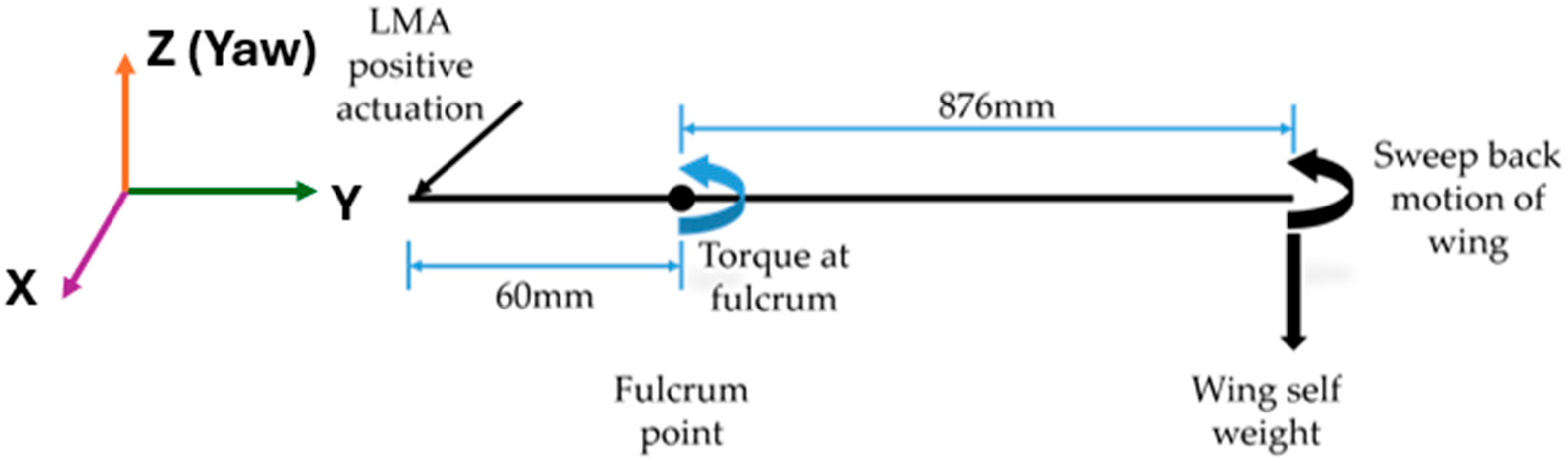
4. Static Torque Calculation for Sweep Actuator Selection
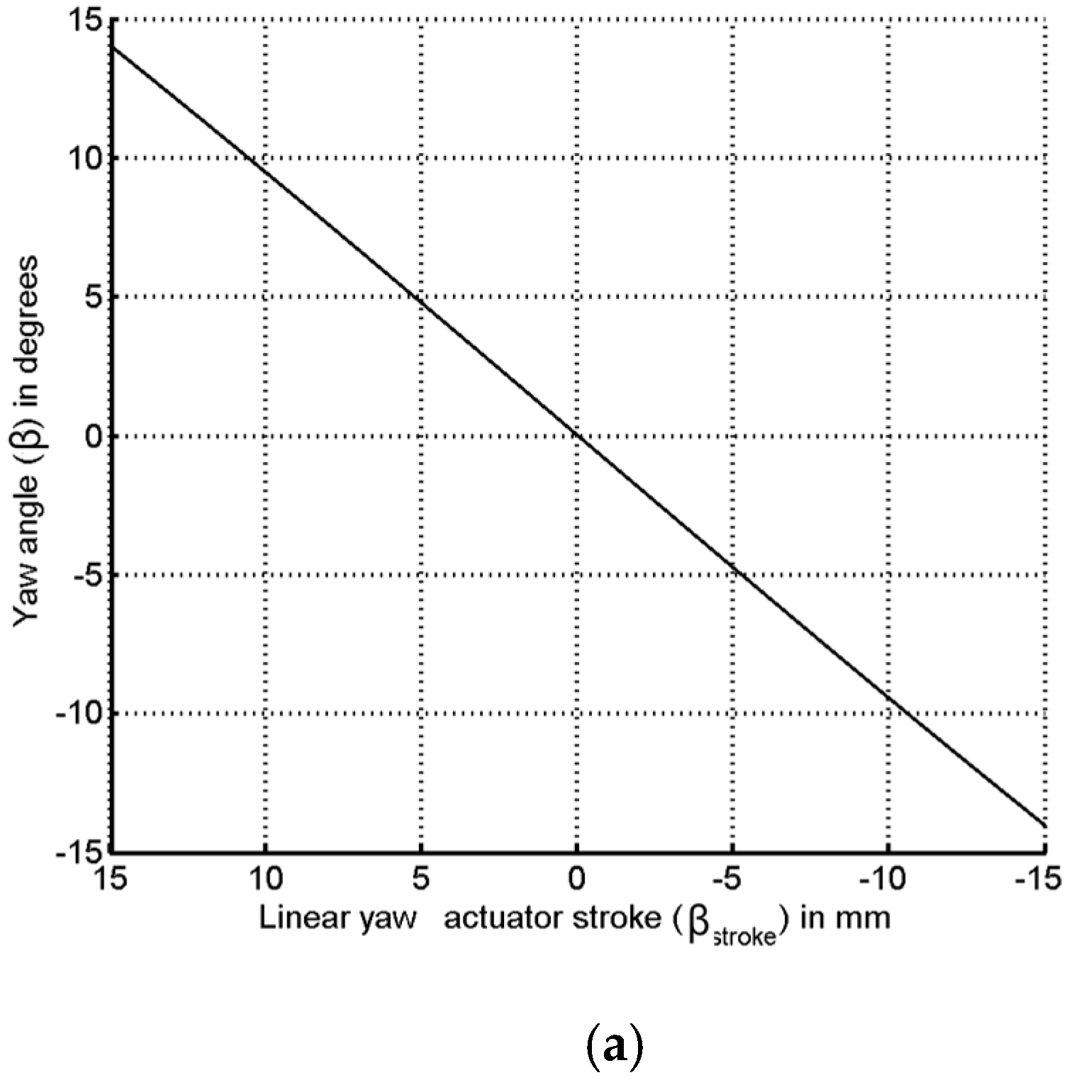
5. LMA Stroke Visualization on MATLAB
6. Single Axis to Multi-Axis Motion Simulation
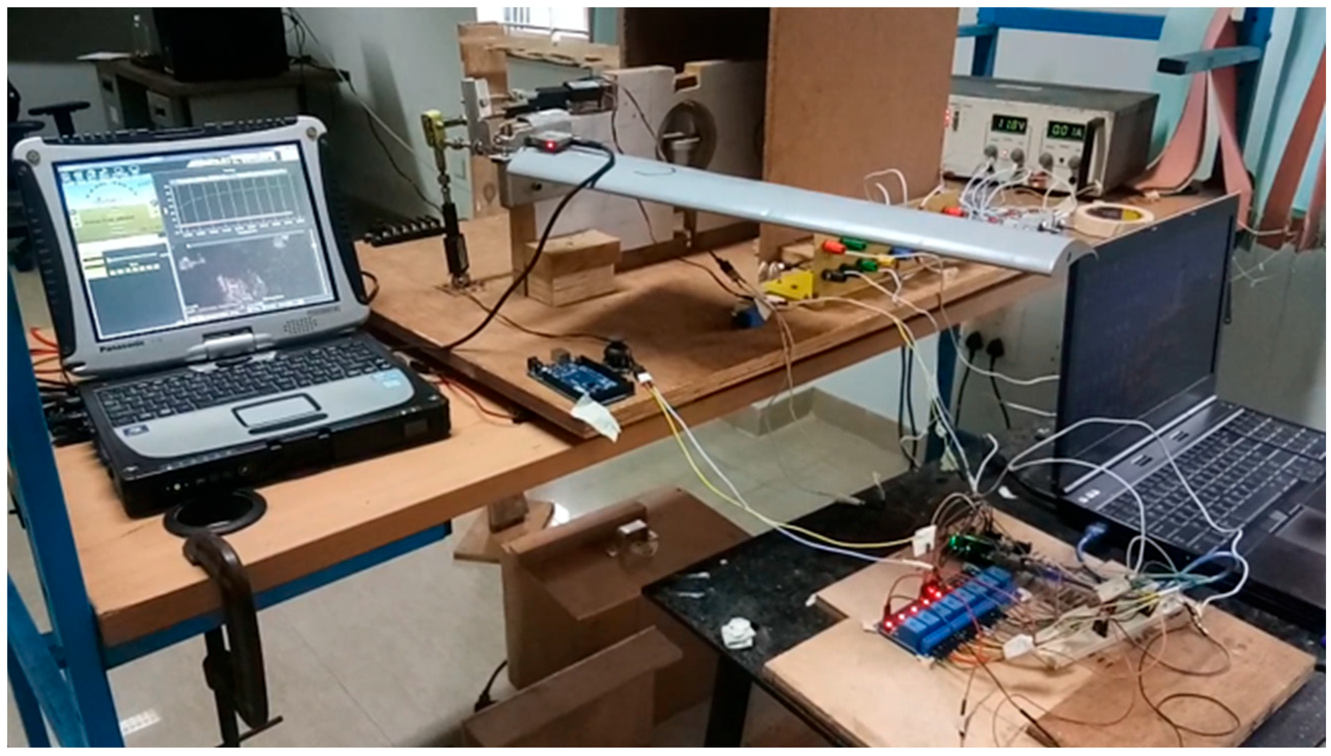
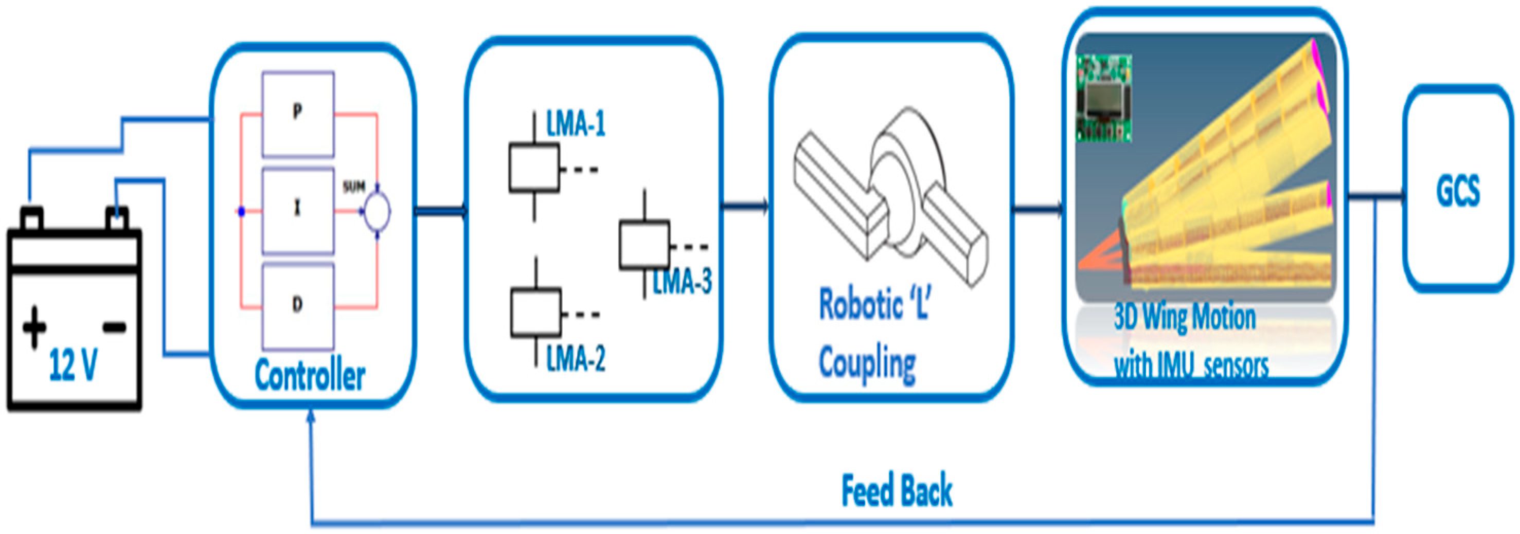
7. Morphing Experiment on Ground Test Rig
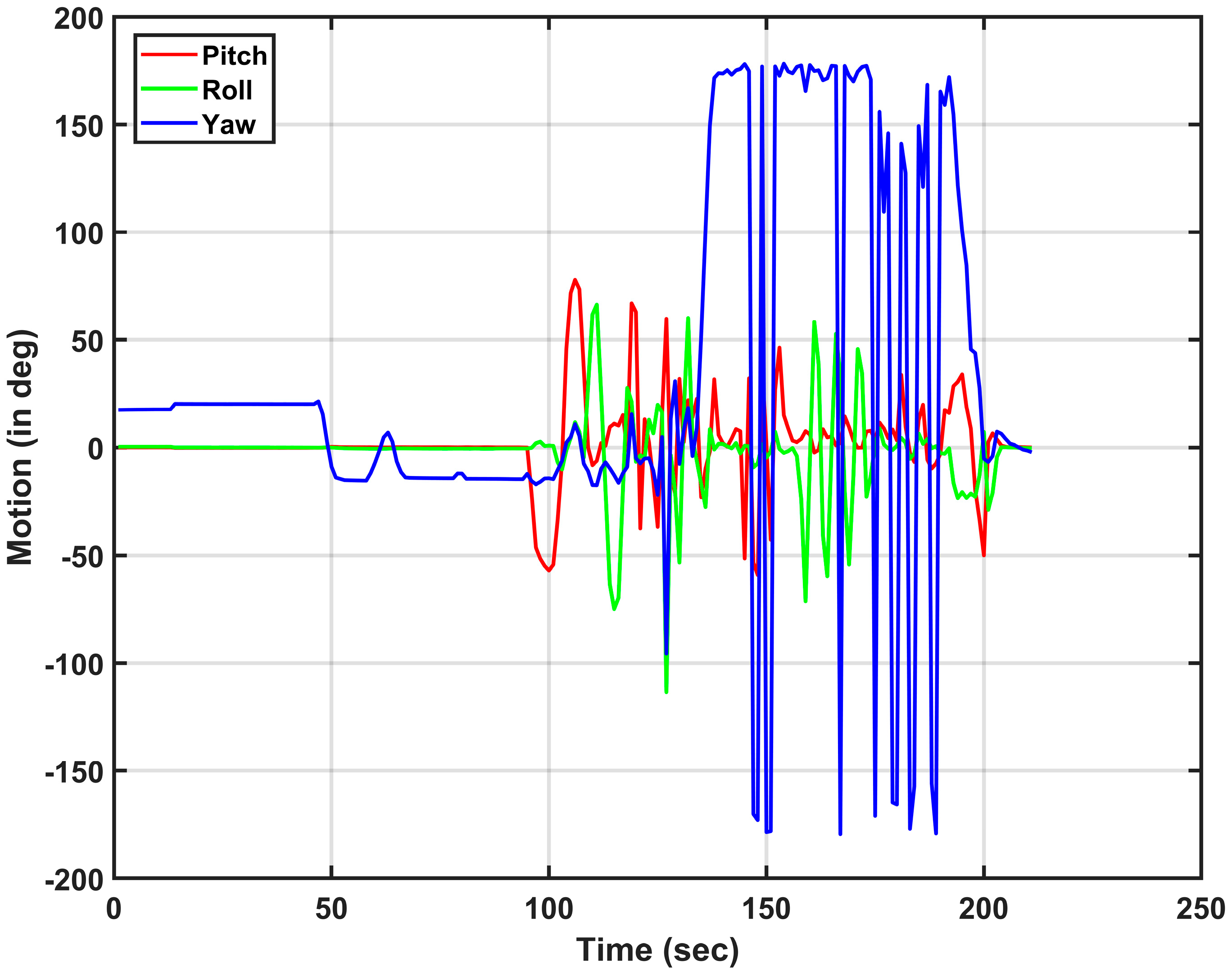
8. Results and Discussions Experimental Test on Ground Test Rig
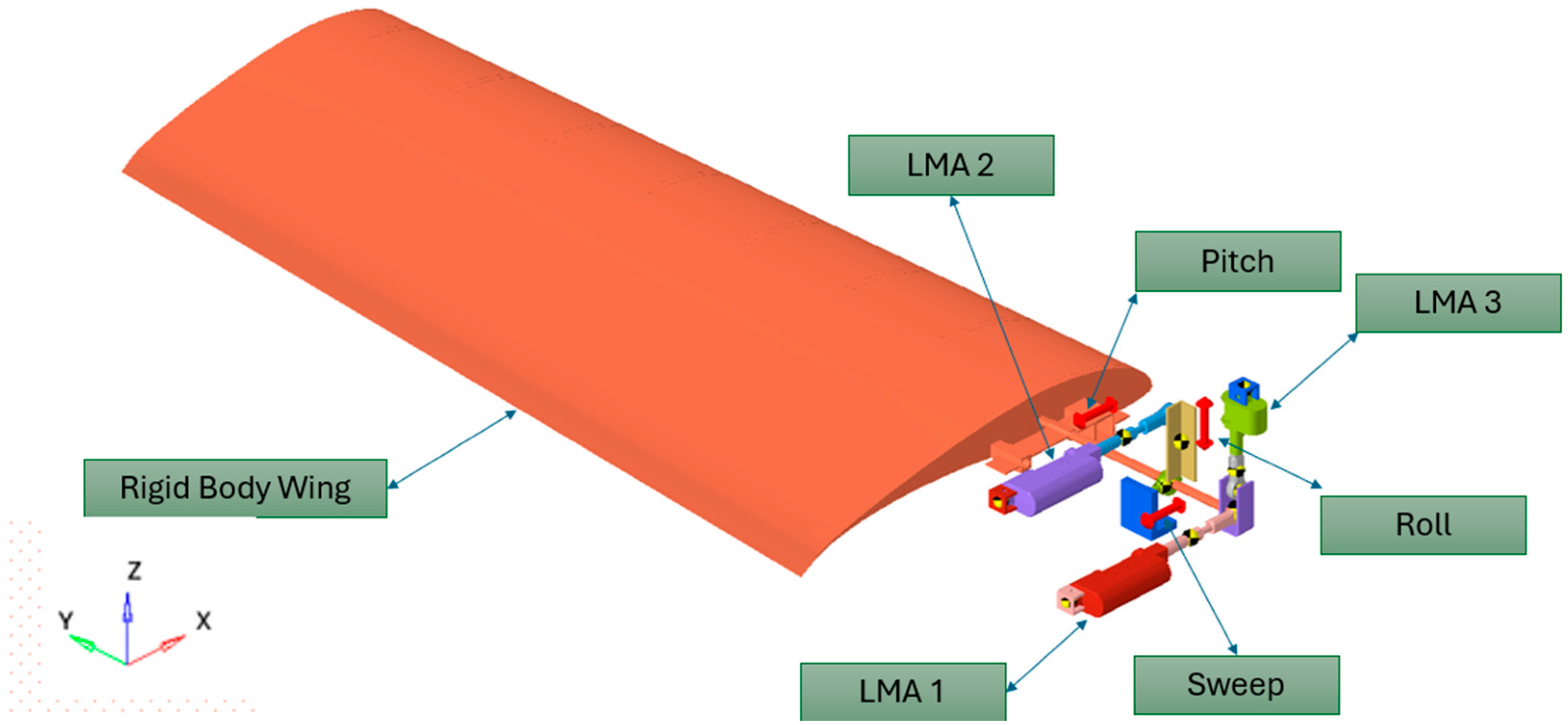
- SDOF can be independently employed with the proposed L coupling for sweep, pitch, and roll, respectively.
- Also in combination, namely sweep-Pitch, Pitch-Roll and Sweep, pitch-Roll may be achieved by L coupling.
- Linear motion is ensured, using LMA’s.
- Since the real-time change in flight parameters is possible to achieve, optimized aerodynamics configurations can be designed in real time for the required aerodynamic performances during flight.
- The designed morphing mechanism is stress and deflection cleared with respect to maneuvering and inertia loads, so that it can be directly scaled up and implemented.
9. Conclusions
Author Contributions
Funding
Data Availability Statement
Acknowledgments
Conflicts of Interest
Abbreviations
| eVTOL | Electric Vertical Take-off and Landing |
| UAV | Unmanned Aerial Vehicle |
| LMA | Linear Miniature Actuator |
| DOF | Degrees of Freedom |
| SDOF | Single Degree of Freedom |
| MDOF | Multiple Degrees of Freedom |
| D-H | Denavit–Hartenberg |
| MBD | Multibody Dynamics |
| RBD | Rigid Body Dynamics |
| CG | Center of Gravity |
| P-R-R | Prismatic-Revolute-Revolute |
| CS | Coordinate System |
| Joint offset | |
| Joint angle | |
| Link length | |
| Twist angle | |
| HTM | Homogeneous Transformation Matrix |
| β | Sweep angle in degrees |
| βs | Sweep stroke in mm |
| First time derivative of sweep angle (velocity of sweeping motion) | |
| Second time derivative of sweep angle (acceleration of sweeping motion) | |
| P-R | Prismatic-Revolute |
| L | Lagrangian function |
| K.E | Kinetic Energy |
| P.E | Potential Energy |
| EOM | Equations of Motion |
| E-L | Euler Lagrange |
| ) | Matrix containing acceleration terms |
| , q) | Matrix containing Coriolis and centripetal terms |
| f(q) | Matrix containing gravity terms |
| M | Matrix containing forces and torques |
| LHT | Left Hand Thumb |
| MW3 | Rod end bearing standard |
| RBD | Rigid Body Dynamics |
| CFD | Computational Fluid Dynamics |
| K.ET | Kinetic energy Total |
| 1 g | Acceleration due to gravity |
| 3 g |
References
- Yuan, Y. Review and Analysis of Variable Swept Wing Technology. Int. J. Mod. Res. Eng. Technol. (IJMRET) 2019, 4, 9–11. [Google Scholar]
- Shanmugam, P.; Raja, S.; Parammasivam, K.M. A study on VGTM actuation system for multi-axis morphing wing of UAV. In Proceedings of the 34th AIAA Applied Aerodynamics Conference, Washington, DC, USA, 13–17 June 2016. [Google Scholar] [CrossRef]
- Kan, Z.; Li, D.; Shen, T.; Xiang, J.; Zhang, L. Aerodynamic Characteristics of Morphing Wing with Flexible Leading-Edge. Chin. J. Aeronaut. 2020, 33, 2610–2619. [Google Scholar] [CrossRef]
- Gomez, J.C.; Garcia, E. Morphing Unmanned Aerial Vehicles. IOP Sci. Smart Mater. Struct. 2011, 20, 103001. [Google Scholar] [CrossRef]
- Weisshaar, T.A. Morphing Aircraft Systems: Historical Perspectives and Future Challenges. J. Aircr. 2013, 50, 337–353. [Google Scholar] [CrossRef]
- Farman, M.; Al-Shaibah, M.; Aoraiath, Z.; Jarrar, F. Design of a Three Degrees of Freedom Robotic Arm. Int. J. Comput. Appl. 2018, 179, 12–17. [Google Scholar] [CrossRef]
- Yan, B.; Li, Y.; Dai, P.; Liu, S. Aerodynamic Analysis, Dynamic Modeling, and Control of a Morphing Aircraft. J. Aerosp. Eng. 2019, 32, 04019058. [Google Scholar] [CrossRef]
- Moosavian, A.; Xi, F.; Hashemi, S.M. Design and Motion Control of Fully Variable Morphing Wings. J. Aircr. 2013, 50, 1189–1201. [Google Scholar] [CrossRef]
- Wang, X.; Zhou, W.; Xun, G.; Wu, Z. Dynamic shape control of piezocomposite-actuated morphing wings with vibration suppression. J. Intell. Mater. Syst. Struct. 2018, 29, 358–370. [Google Scholar] [CrossRef]
- Tong, L.; Ji, H. Multi-body dynamic modelling and flight control for an asymmetric variable sweep morphing UAV. Aeronaut. J. 2014, 118, 683–706. [Google Scholar] [CrossRef]
- Chen, A.; Song, B.; Wang, Z.; Xue, D.; Liu, K. A Novel Actuation Strategy for an Agile Bioinspired FWAV Performing a Morphing-Coupled Wingbeat Pattern. IEEE Trans. Robot. 2023, 39, 452–469. [Google Scholar] [CrossRef]
- Amendola, G.; Diminio, I.; Concilio, A.; Pecora, R.; Amoroso, F. A Linear Guide-Based Actuation Concept for a Novel Morphing Aileron. Aeronaut. J. 2019, 123, 1075–1097. [Google Scholar] [CrossRef]
- Otsuka, K.; Wang, Y.; Palacios, R.; Makihara, K. Strain-Based Geometrically Nonlinear Beam Formulation for Rigid–Flexible Multibody Dynamic Analysis. AIAA J. 2022, 60, 4954–4968. [Google Scholar] [CrossRef]
- Coleman, D.; Benedict, M.; Hrishikeshavan, V.; Chopra, I. Design, Development and Flight-Testing of a Robotic Hummingbird. In Proceedings of the Vertical Flight Society 71st Annual Forum, Virginia Beach, VA, USA, 5–7 May 2015; The Vertical Flight Society: Virginia Beach, VA, USA, 2015; pp. 1–18. [Google Scholar]
- Yun, Z.; Feng, Y.; Tang, X.; Chen, L. Analysis of Motion Characteristics of Bionic Morphing Wing Based on Sarrus Linkages. Appl. Sci. 2022, 12, 6023. [Google Scholar] [CrossRef]
- Tang, D.; Huang, X.; Che, J.; Jin, W.; Cui, Y.; Chen, Y.; Yuan, Y.; Fan, Z.; Lu, W.; Wang, S.; et al. Quantitative Analysis of the Morphing Wing Mechanism of Raptors: Analysis Methods, Folding Motions, and Bionic Design of Falco Peregrinus. Fundam. Res. 2024, 4, 344–352. [Google Scholar] [CrossRef] [PubMed]
- Otsuka, K.; Wang, Y.; Fujita, K.; Nagai, H.; Makihara, K. Multifidelity Modeling of Deployable Wings: Multibody Dynamic Simulation and Wind Tunnel Experiment. AIAA J. 2019, 57, 4300–4311. [Google Scholar] [CrossRef]
- Bin Dulaidi, D. Modeling and Control of 6 DOF Industrial Robot Using Fuzzy Logic Controller. Master’s Thesis, Universiti Tun Hussein Onn Malaysia, Parit Raja, Malaysia, 2014. [Google Scholar]
- Singh, D.; Singh, Y. Development and Analysis of a Five Degrees of Freedom Robotic Manipulator Serving as a Goalkeeper to Train the Football Players. In Proceedings of the IOP Conference Series: Materials Science and Engineering; Institute of Physics Publishing: Bristol, UK, 2018; Volume 402. [Google Scholar]
- Shanmugasundar, G.; Sivaramakrishnan, R.; Venugopal, S. Kinematic Analysis and Software Development of aSeven Degree of Freedom Inspection Robot. World Acad. Sci. Eng. Technol. Int. J. Mech. Mechatronics Eng. 2013, 7. [Google Scholar]
- Tung, T.T.; Van Tinh, N.; Phuong Thao, D.T.; Minh, T.V. Development of a Prototype 6 Degree of Freedom Robot Arm. Results Eng. 2023, 18, 101049. [Google Scholar] [CrossRef]
- Saha, S.K.; Chittawadigi, R.G.; Bahuguna, J. Teaching and Learning of Robot Kinematics Using Robo Analyzer Software AIR ‘13. In Proceedings of the Conference on Advances in Robotics, Pune, India, 4–6 July 2013. [Google Scholar] [CrossRef]
- Sood, S.; Kumar, P. Modelling and Simulation of 3R Robotic Arm. In Advances in Transdisciplinary Engineering; IOS Press BV: Clifton, VA, USA, 2022; Volume 27, pp. 329–334. [Google Scholar]
- Valayil, T.P.; Punnoose Valayil, T.; Selladurai, V.; Rajam Ramaswamy, N. Kinematic Modeling of a Serial Robot Using Denavit-Hartenberg Method in Matlab. Taga J. 2018, 14, 2347–2445. [Google Scholar]
- Amouri, A.; Mahfoudi, C.; Zaatri, A. Dynamic Modeling of a Spatial Cable-Driven Continuum Robot Using Euler-Lagrange Method. Int. J. Eng. Technol. Innov. 2020, 10, 60–74. [Google Scholar] [CrossRef]
- Mustafa, A.M.; Al-Saif, A. Modeling, Simulation and Control of 2-R Robot. Glob. J. Res. Eng. H Robot. Nano-Tech 2014, 14. [Google Scholar]
- Lynch, K.M.; Park, F.C. Modern Robotics: Mechanics, Planning, and Control; Cambridge University Press: Cambridge, UK, 2017. [Google Scholar]
- Raja, S.; Palaniswamy, S.; Dwarakanathan, D.; Parammasivam, K.M. Wind Tunnel Studies on Autonomous Hybrid VTOL UAV with Wing Morphing Technology. In Proceedings of the 2021 21st International Conference on Control, Automation and Systems (ICCAS), Jeju, Republic of Korea, 12–15 October 2021; pp. 244–248. [Google Scholar] [CrossRef]
- Haslwanter, T. Mathematics of Three-dimensional Eye Rotations. Vision Res. 1995, 35, 1727–1739. [Google Scholar] [CrossRef] [PubMed]
- Sun, J.; Li, X.; Xu, Y.; Pu, T.; Yao, J.; Zhao, Y. Morphing Wing Based on Trigonal Bipyramidal Tensegrity Structure and Parallel Mechanism. Machines 2022, 10, 930. [Google Scholar] [CrossRef]


| Conditions | Wing Position | Max CL/CD | |
|---|---|---|---|
| α β γ |  | 16.137 | |
| 0 0 0 | |||
| Un-morphed (Conventional Fixed Wing) | |||
| CL CD | |||
| 0.69034 0.04278 | |||
| α β γ |  | 18.377 | |
| 5 5 5 | |||
| Morphed | |||
| CL CD | |||
| 0.64392 0.03504 | |||
| α β γ |  | 18.045 | |
| 10 10 10 | |||
| Morphed | |||
| CL CD | |||
| 0.64089 0.03552 | |||
| α β γ |  | 17.873 | |
| 12 12 12 | |||
| Morphed | |||
| CL CD | |||
| 0.63823 | 0.03571 | ||
| α β γ |  | 17.544 | |
| 15 15 15 | |||
| Morphed | |||
| CL CD | |||
| 0.63305 0.03571 | |||
| α β γ |  | 18.589 | |
| −5 −5 −5 | |||
| Morphed | |||
| CL | CD | ||
| 0.66998 0.03604 | |||
| α β γ | 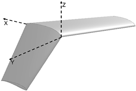 | 18.477 | |
| −10 −10 −10 | |||
| Morphed | |||
| CL CD | |||
| 0.65758 0.03559 | |||
| α β γ |  | 17.545 | |
| −12 −12 −12 | |||
| Morphed | |||
| CL CD | |||
| 0.6881 0.03742 | |||
| α β γ | 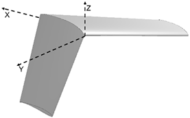 | 17.051 | |
| −15 −15 −15 | |||
| Morphed | |||
| CL CD | |||
| 0.67687 0.03711 | |||
| Link | Joint Offset () | Joint Angle () | Link Length () | Twist Angle () |
|---|---|---|---|---|
| 1 | 168 | 0 | 0 | −90 |
| 2 | 0 | 0 | 60 | 0 |
| 3 | 0 | 0 | 876 | 0 |
| Link | Joint Offset () | Joint Angle () | Link Length () | Twist Angle () | ||||
|---|---|---|---|---|---|---|---|---|
| +15° | −15° | +15° | −15° | +15° | −15° | +15° | −15° | |
| 1 | 183 | 153 | 0 | 0 | 0 | 0 | −90 | 90 |
| 2 | 0 | 0 | 15 | −15 | 60*cos (15) | 60*cos (−15) | 0 | 0 |
| 3 | 0 | 0 | 0 | 0 | 876 | 876 | 0 | 0 |
| Link | Joint Offset () | Joint Angle () | Link Length () | Twist Angle () |
|---|---|---|---|---|
| 1 | 0 | 0 | −90 | |
| 2 | 0 | β* | 60 cos(β*) | 0 |
| 3 | 0 | 0 | 876 | 0 |
| Type and Stroke Length | Operational Voltage | Maximum Load | Stroke Speed | Peak Current | Backlash | Feedback |
|---|---|---|---|---|---|---|
| Electric &30 mm | 12VDC | 45 N | 3.5 mm/s at peak load | 1 A at peak load | 0.1 mm | Open Loop |
Disclaimer/Publisher’s Note: The statements, opinions and data contained in all publications are solely those of the individual author(s) and contributor(s) and not of MDPI and/or the editor(s). MDPI and/or the editor(s) disclaim responsibility for any injury to people or property resulting from any ideas, methods, instructions or products referred to in the content. |
© 2025 by the authors. Licensee MDPI, Basel, Switzerland. This article is an open access article distributed under the terms and conditions of the Creative Commons Attribution (CC BY) license (https://creativecommons.org/licenses/by/4.0/).
Share and Cite
Shanmugam, P.; Kanjikovil Mahali, P.; Raja, S. An Efficient SDOF Sweep Wing Morphing Technology for eVTOL-UAV and Experimental Realization. Drones 2025, 9, 435. https://doi.org/10.3390/drones9060435
Shanmugam P, Kanjikovil Mahali P, Raja S. An Efficient SDOF Sweep Wing Morphing Technology for eVTOL-UAV and Experimental Realization. Drones. 2025; 9(6):435. https://doi.org/10.3390/drones9060435
Chicago/Turabian StyleShanmugam, Palaniswamy, Parammasivam Kanjikovil Mahali, and Samikkannu Raja. 2025. "An Efficient SDOF Sweep Wing Morphing Technology for eVTOL-UAV and Experimental Realization" Drones 9, no. 6: 435. https://doi.org/10.3390/drones9060435
APA StyleShanmugam, P., Kanjikovil Mahali, P., & Raja, S. (2025). An Efficient SDOF Sweep Wing Morphing Technology for eVTOL-UAV and Experimental Realization. Drones, 9(6), 435. https://doi.org/10.3390/drones9060435