Article

FAEM: Fast Autonomous Exploration for UAV in Large-Scale Unknown Environments Using LiDAR-Based Mapping

School of Mechanical and Electrical Engineering, China Jiliang University, Hangzhou 310018, China
*
Author to whom correspondence should be addressed.
Drones 2025, 9(6), 423; https://doi.org/10.3390/drones9060423
Submission received: 15 May 2025 / Revised: 3 June 2025 / Accepted: 6 June 2025 / Published: 10 June 2025

Abstract

Autonomous exploration is a fundamental challenge for various applications of unmanned aerial vehicles (UAVs). To enhance exploration efficiency in large-scale unknown environments, we propose a Fast Autonomous Exploration Framework (FAEM) designed to enable efficient autonomous exploration and real-time mapping by UAV quadrotors in unknown environments. By employing a hierarchical exploration strategy that integrates geometry-constrained, occlusion-free ellipsoidal viewpoint generation with a global-guided kinodynamic topological path searching method, the framework identifies a global path that accesses high-gain viewpoints and generates a corresponding highly maneuverable, energy-efficient flight trajectory. This integrated approach within the hierarchical framework achieves an effective balance between exploration efficiency and computational cost. Furthermore, to ensure trajectory continuity and stability during real-world execution, we propose an adaptive dynamic replanning strategy incorporating dynamic starting point selection and real-time replanning. Experimental results demonstrate FAEM’s superior performance compared to typical and state-of-the-art methods in existence. The proposed method was successfully validated on an autonomous quadrotor platform equipped with LiDAR navigation. The UAV achieves coverage of 8957–13,042 m3 and increases exploration speed by 23.4% compared to the state-of-the-art FUEL method, demonstrating its effectiveness in large-scale, complex real-world environments.

1. Introduction

Autonomous exploration, a key technology in robotics, enables the self-directed investigation of unknown environments by integrating environmental perception, path planning, and information acquisition. Typical applications include infrastructure inspection, 3D modeling, and disaster rescue [1,2,3]. Specifically, recent advances in network optimization and analysis have improved UAV deployment for search and rescue (SAR) operations, including collaborative task allocation, path planning under environmental constraints, and a robust routing framework [4,5]. Quadrotor unmanned aerial vehicles (UAVs), valued for their 3D maneuverability, deployment flexibility, and cost efficiency, are increasingly replacing manual operations in complex scenarios such as mining exploration and industrial inspection. This transition effectively mitigates human operational risks in high-hazard environments. Despite advancements in UAV applications such as in mapping, environmental surveillance, and disaster rescue [6,7], complete autonomy faces key technological bottlenecks. These include the following: (i) generating real-time environmental models and navigational decisions under constrained onboard computation; (ii) improving the robustness of the perception–decision–control chain within unstructured environments [8,9].
The fundamental objective of autonomous exploration is to generate complete and temporally efficient coverage paths. The primary technical challenge lies in making online navigational decisions within unknown environments. Current research methodologies predominantly fall into three categories: sampling-based approaches [9,10,11], frontier-based strategies [12,13,14], and machine learning techniques, including reinforcement learning frameworks. Recent studies have demonstrated that Q-learning can effectively balance exploration efficiency and computational overhead in reward-collecting problems [6], though online optimization remains competitive in dynamic scenarios. This article primarily analyzes the first two widely implemented conventional methodologies.
The sampling-based approach generates random observation points within free space for environmental detection. While demonstrating excellent performance in exploring isolated regions [10], it often encounters local convergence issues in complex environments with multiple subregions. This limitation hinders the planning of optimal routes globally and consequently reduces overall planning efficiency [2]. Existing sampling-based methods often employ greedy strategies that optimize for local information gain. While this improves local information acquisition efficiency, it frequently sacrifices global exploration efficiency.
In contrast, frontier-based exploration strategies identify boundaries between known and unknown space as candidate objectives, directing the robot toward these uncharted territories. While this strategy allows for a global assessment of potential exploration regions, it often leads to oscillatory movement patterns as the robot traverses the environment. This phenomenon stems from the spatially discrete nature of frontier detection. Because new frontiers can appear discretely throughout previously explored areas, the robot must often repeatedly traverse known territory to access them. This repetitive movement consequently generates suboptimal motion trajectories. For example, work in [7] employs frontier strategies to guide ‘next-best-view’ planning and improve exploration efficiency. However, insufficient consideration of UAV dynamic constraints in this work limits flight speed, resulting in unsmooth trajectories and frequent maneuvers. While frontier-based methods demonstrate efficient environment coverage through frontier search and exploration sequence generation, they exhibit significant computational overhead during frontier detection and feature description [15,16]. This computational bottleneck primarily stems from two aspects. First, frontier detection necessitates real-time analysis of high-dimensional environmental map structures. Second, parameterizing frontier features involves complex three-dimensional geometric calculations that require iterative updates in dynamic exploration scenarios. To address this computational challenge, some works, including [15,16,17], propose employing the Traveling Salesman Problem (TSP) to determine an optimal sequence for visiting frontier regions. Therefore, TSP is an NP-hard problem. Its solution complexity increases dramatically with the scale of the environment, imposing significant computational overhead unsuitable for real-time path planning.
Consequently, hybrid exploration frameworks that integrate sampling and frontier-based strategies represent a promising alternative [18,19,20]. However, the fundamental challenge in existing hybrid methodologies lies in effectively coordinating disparate exploration strategies. Conventional approaches typically employ random sampling for localized exploration, which transitions to frontier-based global planning only after the local space has been completely covered. Nevertheless, in practical implementations, this strategic combination exhibits significant limitations. Primarily, the abrupt transition between local and global strategies can trap the system in local optima. Additionally, the lack of coordinated optimization objectives across these strategies results in plans that fail to adequately balance real-time performance with global optimality.
To solve the problems mentioned above, this paper introduces the Fast Autonomous Exploration Method (FAEM) built upon the FUEL framework and designed to facilitate efficient and rapid UAV exploration within complex and expansive three-dimensional environments. The front-end module features a proposed occlusion-free ellipsoid model that enables low-complexity, high-quality viewpoint generation by satisfying geometric constraints. Building on these generated viewpoints, we propose a globally optimized hierarchical exploration strategy. This strategy identifies an efficient global path incorporating high-gain viewpoints. In the global path generation phase, we address frontier-level impacts and path stability concerns such as search failures or excessive time. We utilize an incrementally constructed topological graph for a globally guided, topological kinodynamic path search. This search generates multiple candidate paths that comply with kinodynamic constraints and cover diverse topological structures. Path-guided optimization, leveraging B-spline properties, balances global optimality with local smoothness. We also designed a corresponding quantification method for this process. Once the next exploration target is determined, path planning proceeds based on the global plan. For local trajectory generation, a refinement step samples candidate viewpoints near unobserved clusters and determines observation paths traversing a subset of these viewpoints to efficiently cover more frontier regions. Furthermore, we introduce an adaptive dynamic replanning strategy. This strategy integrates a dynamic start-point selection mechanism with real-time replanning tactics to ensure flight path continuity and stability. The main contributions of this paper are as follows:
(1)
We introduce the occlusion-free ellipsoid, a novel concept enabling low-complexity, high-quality viewpoint generation via geometric constraint solving.
(2)
We propose a globally optimized hierarchical exploration framework. Firstly, it performs globally guided topological kinodynamic path searching using an incremental roadmap, generating multiple candidate paths that satisfy kinodynamic constraints and cover diverse topologies. Subsequently, an optimal global path is selected to access high-gain viewpoints while simultaneously generating highly maneuverable and energy-efficient flight trajectories, effectively balancing exploration efficiency and computational cost. Compared to most existing methods, this framework significantly reduces both memory footprint and computation time.
(3)
We also introduce an adaptive dynamic replanning strategy. This strategy employs a dynamic start-point selection mechanism and a real-time replanning policy to ensure flight trajectory continuity and stability, thereby enhancing exploration efficiency.
(4)
The proposed method was successfully validated on an autonomous quadrotor platform equipped with LiDAR navigation. Extensive simulations and physical experiments validate its effectiveness, demonstrating significant advantages in memory usage optimization, exploration efficiency, and computational speed. The system also demonstrates excellent autonomous navigation capabilities in large-scale, complex, and cluttered scenarios.

2. Related Works

Autonomous exploration has recently garnered widespread research attention from many scholars, leading to the consecutive publication of approaches developed from different viewpoints. This section primarily discusses sampling-based exploration methods, frontier-based exploration methods, and hybrid frontier-sampling exploration methods. Research related to mobile robots mapping unknown environments has been ongoing for many years. While some research, including that addressed herein, concentrates on rapid spatial exploration [1,21], other approaches prioritize precise environmental reconstruction [2].

2.1. Sampling-Based Exploration Methods

Sampling-based exploration methods identify the next-best viewpoint (NBV) by randomly sampling candidate viewpoints in free space and selecting the path yielding the optimal information gain. This approach is fundamentally linked to the Next-Best-Viewpoint (NBV) theory [13,22] and typically employs a rolling horizon strategy within an incremental framework. Bircher et al. [10] pioneered the application of NBV to 3D environment exploration. It operates by iteratively generating random viewpoints in free space, evaluating their information gain (based on unknown area coverage and path cost), and executing the initial segment of the resulting optimal path. While experimental validation showed this scheme’s efficiency in exploring single connected regions [6], it proved prone to local convergence or premature termination in complex environments with multiple sub-regions [6,23]. Subsequent research progressed in two main directions: 3D space extension and algorithm framework optimization. Extensions in 3D space aimed to improve NBV decision quality by adapting RRT to 3D reachable spaces and incorporating factors like localization uncertainty [24] and object visual saliency [25]. Framework optimization focused on addressing tree structure redundancy, for example, through roadmap-based knowledge reuse mechanisms [26,27]. Further improvements include GBP [28] and MBP [29]. GBP constructs a topological global map during local exploration and triggers global replanning to guide the Unmanned Aerial Vehicle (UAV) to unexplored areas upon completing a local region or reaching a dead end [28]. MBP utilizes motion primitives to build the RRT, thereby ensuring the dynamic feasibility of the generated trajectories [29]. Other work incorporated the dynamic rewiring strategy of RRT* for continuous tree structure optimization [2]. Additionally, research introduced an innovative direct sampling approach using motion primitives [22]. This approach filters for safe, feasible motion units with the highest information gain, significantly improving the efficiency of autonomous exploration.

2.2. Frontier-Based Exploration Algorithms

Frontier-based exploration represents a foundational strategy in robot environment exploration, initially proposed by Yamauchi [13]. The frontier in this strategy signifies the interface between known and unknown regions within the environment. The core idea is to direct the robot toward these frontiers to observe new regions, thereby accomplishing the exploration task. Traditional frontier detection methods typically require processing the entire map each time they are invoked, which makes them inefficient, particularly in 3D scenarios. Keidar et al. [30] proposed two methods: the Wavefront Frontier Detector (WFD) and the Fast Frontier Detector (FFD). WFD uses incremental map updates to reduce computational complexity, but its efficiency decreases as the environment size grows. FFD constructs frontiers from sensor reading contours; however, its reliance on 2D LiDAR and frequent invocations can lead to computational redundancy. The subsequent FTFD algorithm [31] improved real-time performance by restricting detection to boundary regions within the sensor’s Field of View (FOV). This method searches for new exploration regions, assuming decreasing entropy for each grid cell [32]. However, this assumption fails in the presence of dynamic obstacles or sensor noise. Work by [16] employed Axis-Aligned Bounding Boxes (AABBs) to accelerate detection. When free cells are observed, a Region Growing (RG) algorithm simplifies the detection process. Nevertheless, redundant scanning within the AABB structure remains a limitation. In contrast, the study in [33] fused path planning with frontier extension, navigating toward the boundary between free and unknown space to expand the map. Work in [1] optimized Unmanned Aerial Vehicle (UAV) movement by extracting sensor FOV boundaries. One study [34] used the Traveling Salesperson Problem (TSP) framework to determine boundary visiting sequences, while another [35] adopted an information-gain-based policy for selecting exploration targets. Frontier exploration was initially introduced in 2D space [36], where the closest frontier was selected as the next objective. This approach was later adapted to 3D space using Stochastic Differential Equations (SDEs) [37]. A study [38] integrated sampling-based local exploration with frontier-based global exploration. This approach employed an incremental frontier representation and hierarchical planning to address challenges, including inefficient global coverage, conservative trajectories, and high decision-making frequency.

2.3. Hybrid Frontier-Based and Sampling-Based Algorithms

Some approaches integrate frontier-based and sampling-based exploration within a unified framework [18,39]. If a robot becomes trapped in a local optimum, frontier information guides it toward unexplored global regions. However, AEP only caches frontier positions, requiring a separate path planner to compute global exploration paths. This framework extracts frontiers from the environment map, then samples candidate exploration points within these frontier regions, and finally identifies the best viewpoint through evaluation. Wang et al. [20] proposed a method of incrementally building a roadmap and extracting frontier boundaries around the roadmap nodes. This roadmap enables efficient querying of information gain and arrival cost for each candidate exploration point. However, this approach requires extending the roadmap after each scan, and the associated frontier detection algorithm does not guarantee completeness [40].
Recent advancements in deep learning have led to a growing number of autonomous exploration methods based on deep reinforcement learning [41]. Through extensive training in simulated environments, these methods learn to directly generate robot actions from perceptual information to facilitate environment mapping. However, most current approaches are primarily suited for indoor settings. Developing learning-based methods applicable to large-scale, complex environments remains an open challenge. Conventional exploration strategies both possess innate limitations. While combining them in a unified framework can potentially improve exploration efficiency, existing hybrid methods often suffer from loosely coupled integration or reliance on locally greedy decisions. Therefore, we introduce a novel frontier-sampling hybrid method designed for efficient exploration for Unmanned Aerial Vehicles (UAVs) in complex 3D environments.

2.4. Quadrotor Trajectory Planning
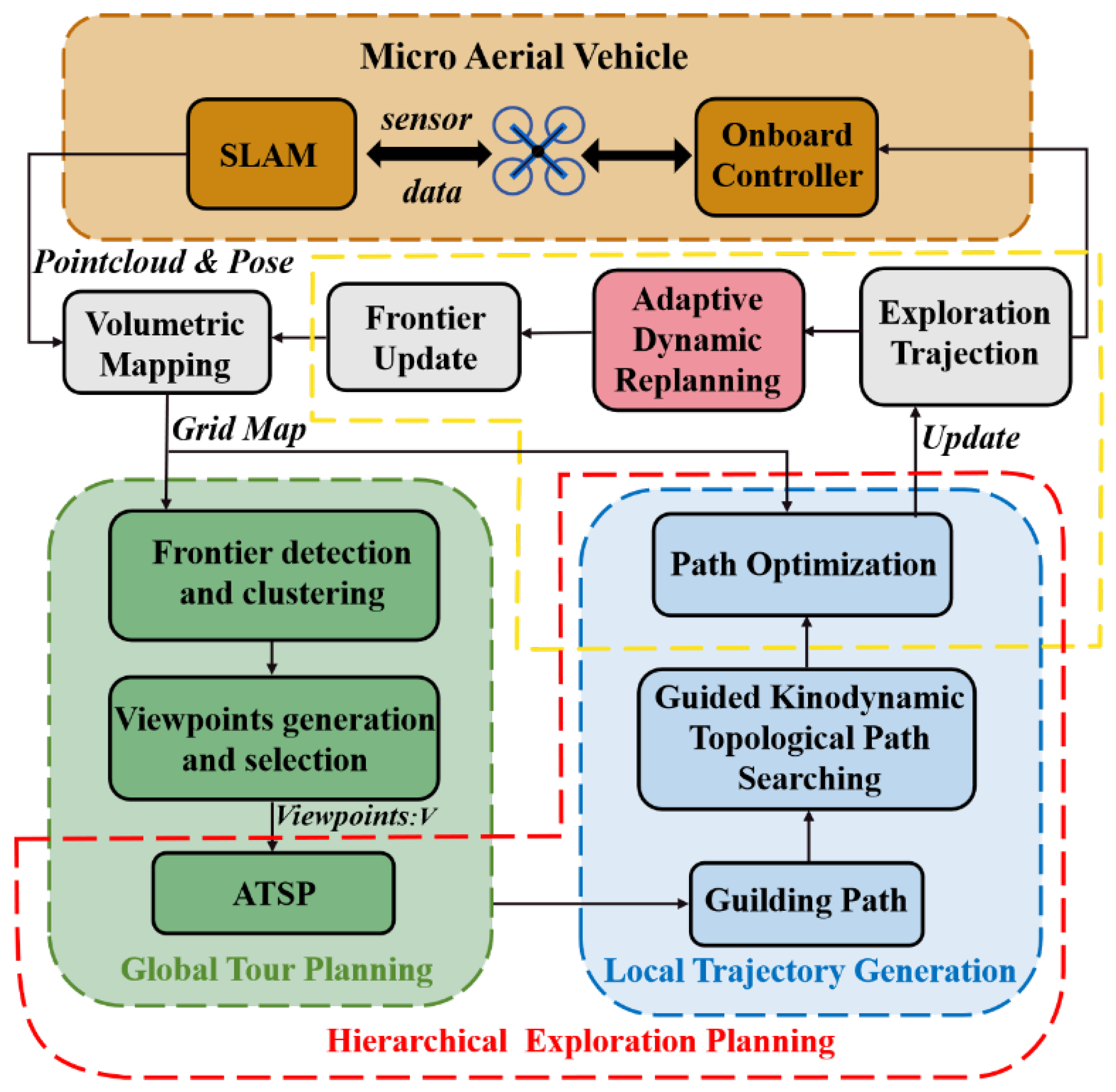
Gradient-based motion planning is a primary method for local Unmanned Aerial Vehicle (UAV) trajectory generation, formulating the problem as an unconstrained nonlinear optimization task. Ratliff et al. [42] introduced the Euclidean Signed Distance Field (ESDF) to robot motion planning. The obstacle gradient information provided by ESDF has since been widely used for trajectory optimization in configuration space. However, discrete-time optimization techniques [42,43] are limited by the high sensitivity of UAVs to dynamic constraints. Although continuous-time polynomial trajectory optimization approaches [44] were subsequently developed, they suffer from significant computational costs for potential function integration and exhibit relatively low success rates, even with random restart strategies. To mitigate this issue, B-spline trajectory parameterization methods [4] leverage their convex hull property to enhance optimization efficiency. Further improvements in UAV planning performance involve using a collision-free initial path from a front-end planner [10] and considering kinodynamic constraints during path generation.
Within this framework, one study [45] employed covariant gradient descent to minimize smoothness and collision costs for discrete-time trajectories. In contrast, another study [46] attempted to alleviate local minima using stochastic iterative sampling, albeit at a high computational cost. Subsequent work, such as [47], incorporated optimizations using continuous-time polynomials and uniform B-splines, leveraging their convex hull properties. Although these methods improved efficiency, their performance remained dependent on the initial trajectory’s quality. Although Zhou et al. [48] incorporated environmental awareness to improve robustness, current approaches still struggle with the trade-off between success rate and trajectory quality, as they have not fundamentally overcome the local optima issue.
This paper presents a path-guided refinement method that integrates geometric path guidance into the refinement process. By effectively guiding the optimization process away from infeasible local minima, this geometric path guidance significantly improves the planning success rate. Our trajectory planning method builds upon the EGO-planner [49] and extends it to optimize all parameters of the B-spline. This approach allows for minimizing the total trajectory duration. Furthermore, integrating multiple diverse paths from topological path searching with the path-guided optimization technique enhances trajectory quality by exploring different local optima. This enables the exploration of unknown space at higher navigation speeds.

3. System Overview

The autonomous exploration system framework presented in this work, depicted in Figure 1, is an enhancement and development based on the FUEL [36] framework. Initially, the SLAM module processes sensor data to generate Unmanned Aerial Vehicle (UAV) localization estimates and registered point clouds. Based on the SLAM output, a local 3D occupancy grid map centered around the UAV’s current location is maintained. This map also incorporates frontier updates. The map serves purposes including the detection of frontier clusters, the generation of effective viewpoints, the construction of a topological roadmap, and provides foundational support for global planning and local refinement phases. Secondly, global exploration planning is conducted by comprehensively considering flight factors and frontier-level factors. Subsequently, the hierarchical planning exploration module executes path planning based on the global planning results, initializes multi-objective optimization using candidate paths, and generates kinodynamically feasible topological search paths. The local refinement stage samples candidate viewpoints near frontiers requiring initial observation. It then identifies an observation trajectory passing through a subset of these viewpoints to effectively cover adjacent frontiers. Finally, based on the planned path, the trajectory optimization component generates smooth, safe trajectories for execution by the flight control system. This entire process repeats iteratively based on the defined replanning strategy.
Specifically, system modules operate at different rates. Global planning and local trajectory generation run sequentially at a predefined frequency to determine the exploration path. SLAM output and map updates operate synchronously with the sensor (e.g., 10–20 Hz for LiDAR), ensuring timely environment representation. Trajectory optimization executes at a high frequency (≥ 30 Hz ) to maintain flight safety.

4. Proposed Approach

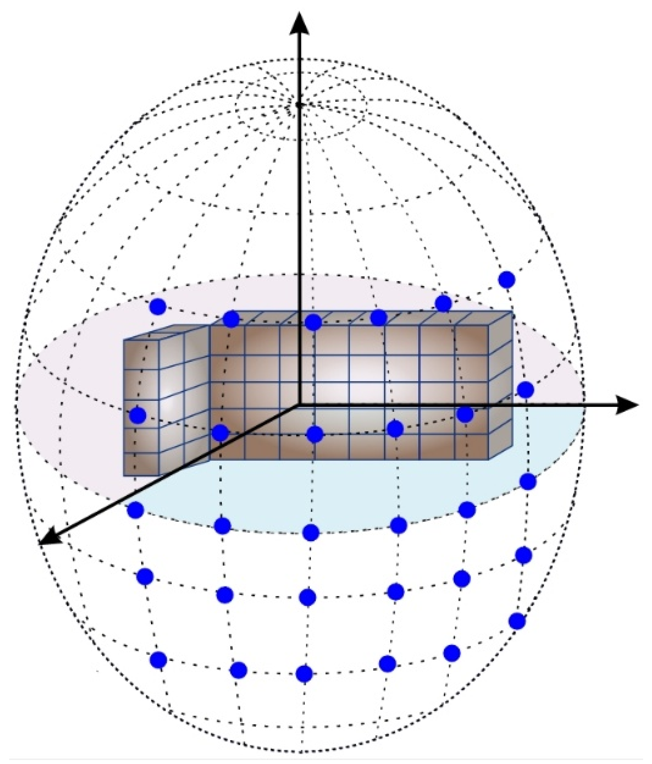
4.1. Occlusion-Free Ellipsoid

An occlusion-free ellipsoid is specified by its center P c R 3 , situated on the target frontier, along with its semi-axis lengths ( a , b , c ) . Let P o denote the set of all obstacle points in the environment. For a given frontier center P c , we define p o P o as the nearest obstacle point along each axis direction. The semi-axis lengths ( a , b , c ) are computed as the minimum Euclidean distances between P c and p o in the x, y, and z dimensions, respectively:
a = min P o Obstacles p c . x p o . x
b = min P o Obstacles p c . y p o . y
c = min P o Obstacles p c . z p o . z
Wherein p o . x , p o . y , p o . z R 3 represent the nearest neighboring obstacle points (NNS). This definition ensures that the ellipsoid’s interior contains no occupied grid cells. Due to its convexity, any line segment connecting a point inside or on the ellipsoid surface to its center P c (located on the frontier) remains within the occlusion-free volume. Viewpoints are sampled on the ellipsoid surface using its parametric equation (Equation (4)). The sampling density can be adjusted along the principal axes, for instance, by increasing density along the major axis.
p ( θ , φ ) = P c + a cos θ cos φ b cos θ sin φ c sin θ θ π 2 , π 2 , φ [ 0 , 2 π ]
To accelerate the ellipsoid generation process, we utilize the incremental KD-tree method and Principal Component Analysis (PCA) proposed in the work [50].
First, the principal axis directions V 1 , V 2 , V 3 are determined. PCA is applied to analyze the obstacle distribution, and the eigenvectors of the resulting covariance matrix define these three orthogonal principal axes for the ellipsoid. The first principal component (corresponding to the largest eigenvalue) indicates the direction of greatest variance (often correlated with the lowest obstacle density) and defines the ellipsoid’s major axis. Second, the semi-axis lengths are calculated. Along each principal axis direction V 1 , V 2 , V 3 , the nearest obstacle point is found efficiently using a KD-tree (time complexity O ( log n ) , where n represents the number of nodes). Each semi-axis length corresponds to the minimum distance from the ellipsoid center P c to the nearest obstacle found along that respective principal axis direction. Since this calculation is performed independently for each of the k downsampled frontier cells (each requiring searches along three axes), the overall complexity for generating all ellipsoids is O ( k log n ) . k is indeed user-defined, allowing flexibility in adjusting the downsampling rate based on the specific requirements of the exploration task and computational resources. However, to maintain computational efficiency, we set an upper bound on k ( k 200 ). The overall complexity of the algorithm is primarily dependent on the number of nodes in the tree, ensuring scalability for large-scale environments [51]. Consequently, the proposed approach enables efficient viewpoint generation by avoiding global searches, even in large environments. This procedure, termed GenerateNewEllipsoid ( P c ), will be used in the subsequent analysis.

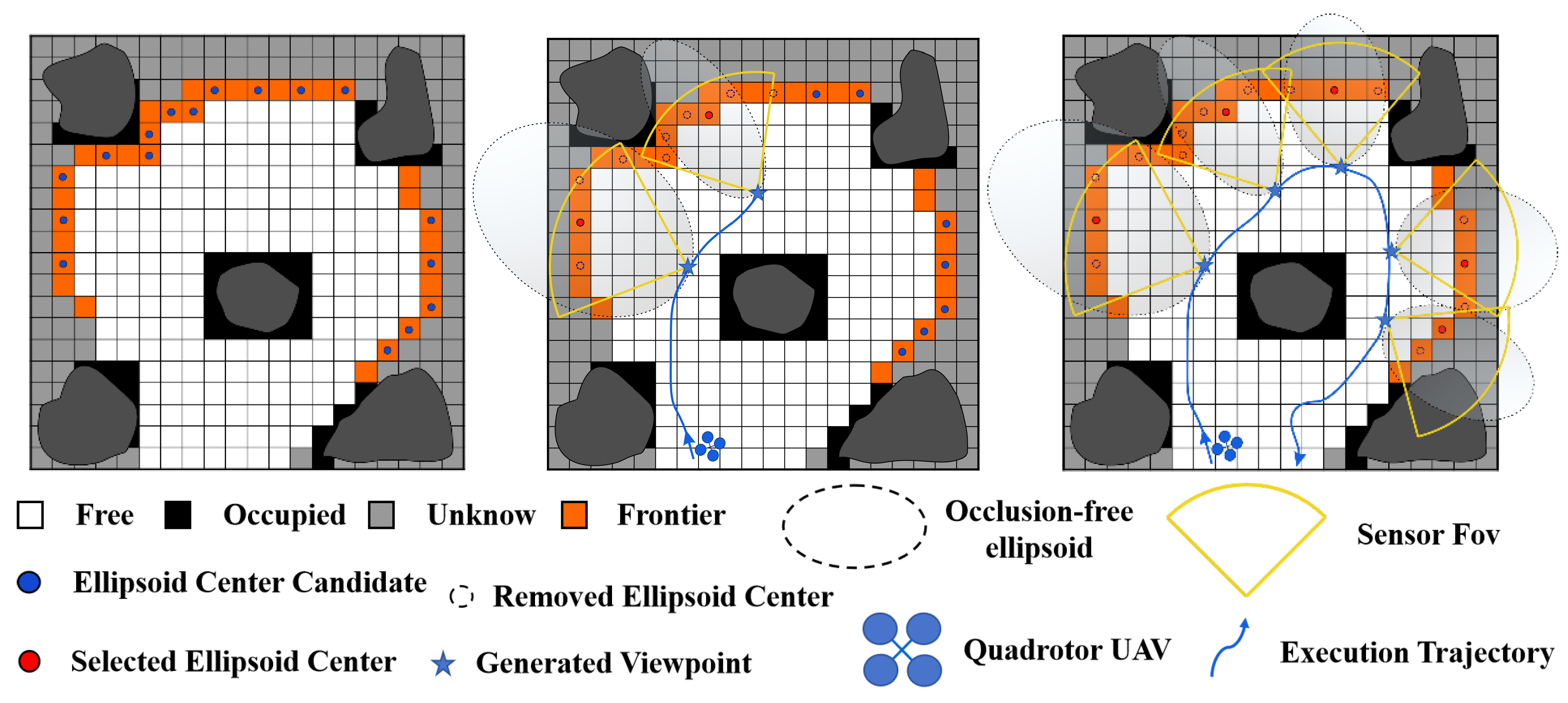
4.2. Viewpoints Generation

Following the generation of the occlusion-free ellipsoid e l , the introduced parameterization method, derived from the ellipsoid’s equation, samples a collection of viewpoints uniformly across the ellipsoid’s surface, illustrated in Figure 2 Viewpoints located on the ellipsoid surface utilize its geometric properties more effectively than interior viewpoints. This approach is particularly beneficial in asymmetrical environments, such as areas with dense obstacles or elongated tunnels, as it facilitates targeted coverage of frontier cells with varying orientations. The orientation of the sampled viewpoints is subsequently optimized by aligning the sensor heading with the principal axes of the ellipsoid, thus maximizing the coverage of frontier cells. Subsequently, viewpoints located in unknown space are discarded. Then, sensor field-of-view (FOV) constraints are evaluated, and the ellipsoid equation is used to quantify the number of frontier cells covered by each viable viewpoint. Finally, the viewpoint providing the maximum frontier cell coverage is selected. This entire procedure is termed GenerateViewpoints with Ellipsoids e l , F and will be referenced in subsequent analyses.
Algorithm 1 details the viewpoint generation process. Firstly, the algorithm incrementally identifies frontier cells ( F ) within the environment. Next, these frontier cells ( F ) are uniformly downsampled to produce a candidate set C of potential ellipsoid centers using the DownsampleFrontier ( ( F ) ) procedure. Secondly, for each ellipsoid center P c in the candidate set C , GenerateNewEllipsoid ( P c ) generates the corresponding occlusion-free ellipsoid e l . Subsequently, each generated ellipsoid e l is inserted into a priority queue S, ordered by decreasing volume. In each iteration, the ellipsoid e l with the maximum volume is selected from S. Then, GenerateViewpoint e l , F is called to determine the viewpoint V b that provides the best coverage of the current frontier cells F . The selected viewpoint V b includes a group of frontier cells F v F . These covered cells F v are removed from the set F , and the processed ellipsoid e l is removed from the priority queue S. The process repeats until the priority queue S is empty. However, if the volume of the selected ellipsoid e l falls below a predefined threshold, a viewpoint V b is generated using a spherical coordinate system approach, similar to FUEL [16], instead of using GenerateViewpoint e l , F .
Algorithm 1 Generate viewpoints with ellipsoids
1:
Input: F
Output: V
2:
C = DownsampleFrontier ( F );
3:
for  P c C   do
4:
       e i = GenerateNewEllipsoid P c ;
5:
      S. Append e i ;
6:
end for
7:
while not S.empty do
8:
       e l = S .front();
9:
      S. pop();
10:
      V b , F v , S v = GenerateViewpoint e l , F ;
11:
     F.remove F v ;
12:
     S.remove S v ;
13:
     V.Append( V b );
14:
end while
15:
return V
In this paper, specifically for viewpoint sampling based on the ellipsoidal parameterization system, the minimum sampling-related value (ellipsoid volume) corresponds to the same semi-axis ratio as e l , and the maximum sampling volume value is set to three to four times the minimum value. In cases involving smaller ellipsoids (e.g., volumes near the threshold or when the spherical method is triggered), ray casting can be employed to assess frontier coverage if necessary. The associated computational cost is considered low because these smaller volumes typically encompass fewer frontier cells. This described part is referred to as the algorithm’s front-end. Figure 3 provides a diagram of the entire process.
As previously discussed, viewpoints located at a distance from the frontier may enhance the coverage of frontier cells but are also more susceptible to occlusion by obstacles. This paper’s proposed approach generates occlusion-free ellipsoids, ensuring clear visibility from the viewpoint of all frontier cells enclosed within the ellipsoid. Our technique differs from conventional approaches and employs [52] occlusion-free spheres defined by a single radius. The uniform viewpoint distribution on a sphere requires dense sampling in asymmetrical environments (e.g., narrow passages) to ensure coverage along critical directions. Furthermore, a sphere’s volume is easily constrained by nearby obstacles, limiting its potential coverage. Moreover, optimizing coverage for specific directions is difficult with spheres, and their use in narrow channels can generate numerous invalid viewpoints, causing computational redundancy. Because its radius is determined by the nearest obstacle globally, a sphere struggles to adapt dynamically to local environmental changes (e.g., the appearance of dynamic obstacles). In contrast, our proposed method overcomes these limitations by generating environment-adaptive ellipsoids and employing dynamic directional optimization. Firstly, the ellipsoid shape is adapted using Principal Component Analysis (PCA) on the local obstacle distribution. This dynamically aligns the ellipsoid’s three orthogonal principal axes, with the major axis typically oriented along directions of low obstacle density (e.g., corridors, open spaces) and the minor axes oriented away from high-density areas. Consequently, large-volume ellipsoids are generated in open regions, allowing viewpoints along the major axis to cover distant frontier cells. Conversely, smaller ellipsoids are formed in cluttered environments, positioning viewpoints (often aligned with shorter axes) closer to the frontier to maintain occlusion-free paths. This anisotropic design allows the ellipsoid to conform better to asymmetrical environmental structures, offering flexibility to extend coverage into unexplored areas while maintaining the occlusion-free property. Secondly, during viewpoint generation, parameterized directional sampling is used. Viewpoint density can be increased along the major axis (typically the direction of lowest obstacle density). This is combined with dynamic yaw angle optimization to align the sensor’s field of view (FOV) with the primary exploration direction, maximizing coverage efficiency.
By comparison, conventional approaches such as FUEL [16] necessitate dense sampling in the radial dimension of cylindrical coordinates to yield viewpoints with high coverage, demanding ray casting validation for every sample point, which results in a substantial surge in computation. Leveraging its volume-prioritization strategy and the inherent convexity of the ellipsoids, our approach significantly reduces the need for expensive ray casting to assess coverage. The ellipsoid’s convexity ensures that paths from its surface to the enclosed frontier cells are occlusion-free, eliminating the cost of individual path collision checks. For small-volume ellipsoids in complex local areas, the algorithm balances precision and efficiency using techniques like semi-axis extension and hybrid strategies, further reducing the computational load. This makes the algorithm robust and suitable for real-time performance in large-scale unknown environments.

4.3. Global Tour Planning

The gain of a viewpoint v is defined as
g ( v ) = V ( e ) e λ c ( v , ξ )
Wherein V ( e ) represents the volume of the related ellipsoid, calculated as V ( e ) = 3 4 π a b c . wherein a , b , and c denote the lengths of the three semiaxes of the ellipsoid, which are determined by the minimum distances to obstacles along the x , y , and z axes, respectively. c ( v , ξ ) represents the movement cost of the drone from its current configuration ξ to the viewpoint v, evaluated as their Euclidean distance. λ is the adjustment factor.
The proposed method utilizes a prioritized queue of viewpoints denoted as Q, which is maintained at a fixed size n q . As elaborated in Section 4.2, the method generates a set of n v viewpoints, denoted as V. For each viewpoint v i in V, its gain g v i , incorporating the geometric properties of the occlusion-free ellipsoid, is computed using Equation (5). Viewpoints are then greedily selected based on the highest gain (determined by ellipsoid volume and obstacle-free coverage) and pushed into the priority queue Q until it is full. This process ensures that Q contains the viewpoints deemed most informative according to the defined gain metric.
An n q × n q cost matrix M q is defined, where each element denotes the linkage expense between two viewpoints in Q. This linkage expense is determined by the distance of an obstacle-free path identified using the A* algorithm while taking into account environmental geometric constraints. The problem is analogous to the FUEL method in that it is structured as an Asymmetric Traveling Salesman Problem (ATSP) and is addressed using the algorithm delineated in [53]. The viewpoints in Q are generated based on the geometric properties of the occlusion-free ellipsoids, specifically their semi-axes ( a , b , c ) and orientation. Consequently, the connection cost calculation and overall tour planning must account for the ellipsoid’s shape characteristics: The semi-axes lengths ( a , b , c ) affect feasible approach directions, as the vehicle must maintain safe obstacle clearance along all three axes. The ellipsoid’s orientation influences path curvature constraints, especially in narrow spaces where vehicle alignment with the ellipsoid’s principal axes is necessary to avoid collisions. The backend of the exploration planner thus incorporates these ellipsoid-specific geometric parameters into the cost matrix calculation, ensuring the generated tour is efficient and collision-free, particularly in asymmetric environments.

5. Hierarchical Exploration Planning

The Hierarchical Exploration Planning module includes three primary components: an incrementally built topological graph G , a globally guided kinodynamic topological path planner, and a local trajectory planner. The module also integrates B-spline trajectory optimization and features an adaptive dynamic replanning strategy.

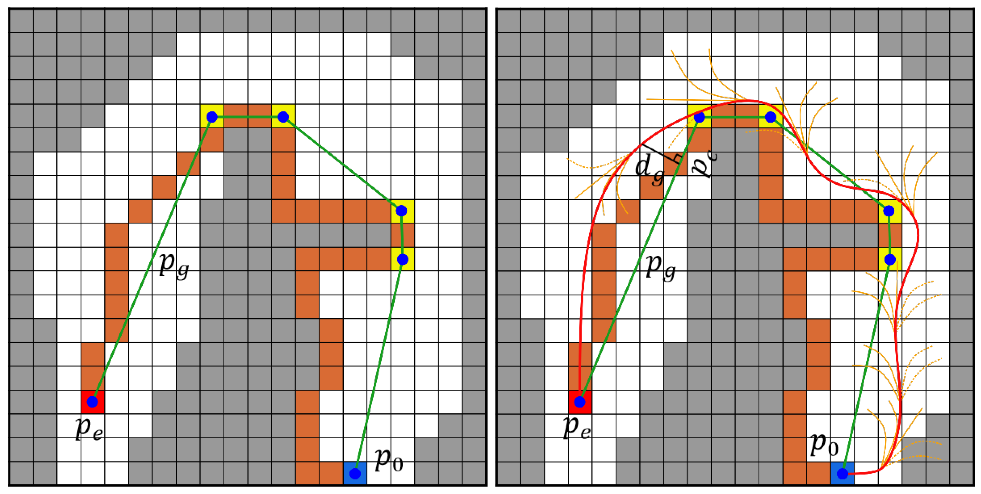
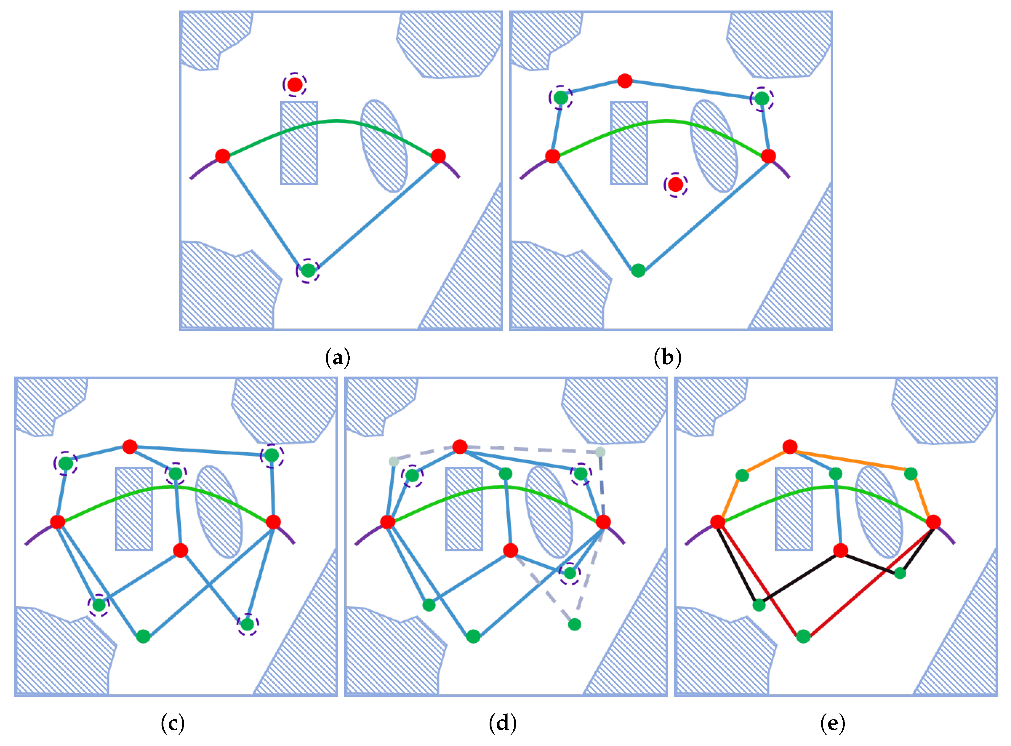
5.1. Global Kinodynamic Topological Path Searching

In specific scenarios, such as navigating from indoors to outdoors, standard kinodynamic path searching can suffer from prolonged computation times or search failures, potentially trapping the UAV in inefficient “stop-start-replan” cycles. To ensure stable and efficient path planning, this work employs the guided kinodynamic topological path search approach illustrated in Figure 4. An optimal path is generated following the Pontryagin Minimum Principle [23] when the spacing d e between points p c and p e along the pruned guiding path P g , constructed via the A* algorithm, falls below 3 or the path contains fewer than two waypoints (turns).
p μ * ( t ) = 1 6 α μ t 3 + 1 2 β μ t 2 + v 0 + p 0
α μ β μ = 1 T μ 3 12 6 T μ 6 T μ 2 T μ 2 p n p 0 v 0 T μ v n v 0
J * T μ = μ { x , y , z } 1 3 α μ 2 T μ 3 + α μ β μ T T μ 2 + β μ 2 T μ
Wherein v n denotes the target velocity. Minimizing the trajectory cost J * T μ yields a feasible trajectory. Alternatively, we adopt the guided kinodynamic topological path search approach, which introduces a novel heuristic function:
h c = λ 1 d e + λ 2 d g + λ 3 d θ , f c = g c + h c
Wherein d e signifies the distance between points p c and p e along the guiding path, aimed at improving search efficiency; d g restricts the path search domain to the neighborhood surrounding the guiding path; and d θ contributes to optimizing path smoothness.
The proposed path-guided optimization method, when provided with a geometric guiding path, is capable of replanning a locally optimal trajectory. However, as illustrated in Figure 5, the trajectory resulting from even the shortest geometric path guidance may not always yield an optimal solution. Indeed, determining the optimal guiding path is challenging because geometric paths lack higher-order information (such as velocity and acceleration) and fail to completely represent the true motion state. Although kinodynamic path searching addresses these limitations, finding an ideal path becomes computationally expensive when start and end point boundary state constraints are imposed on the replanned trajectory [54]. Achieving better solutions requires considering diverse paths. To address this challenge, a topological path search method using kinodynamic sampling is proposed to generate a diverse set of paths, offering multiple topological guidance options. Although existing methods [55,56] address this problem, they typically cannot operate in real time within complex 3D environments. Through careful algorithmic redesign, this work presents a real-time solution for this challenging problem [57].
Algorithm 2 constructs a kinodynamically aware UVD roadmap, denoted as G , which encompasses a set of paths exhibiting diverse topologies and kinodynamic characteristics derived from various UVD classes. Conventional Probabilistic Roadmaps (PRMs) tend to produce numerous redundant cycles. In contrast, Generalized Voronoi Diagrams (GVDs) prioritize safety by generating paths along the medial axis to maximize obstacle clearance. However, while potentially safer, these GVD-based paths often exhibit limited topological diversity. Conversely, the roadmap generated by the proposed approach is more concise, typically containing one or a few representative paths for each UVD category, as illustrated in Figure 6. Building upon the Visibility PRM concept [58] this work introduces two classes of graph nodes that incorporate explicit kinodynamic constraints: Pioneer nodes and Edge nodes.
Algorithm 2 Kinodynamic Topological Roadmap
1:
InitGraph ( G ) , AddPioneer G , s , x s , AddPioneer G , g , x g
2:
  t 0 , N 0
3:
 while  t t max N sample N max do
4:
       P = Sample()
5:
       V = VisibleNode ( G , P )
6:
      if  | V | = = 0  then
7:
           AddNode( G , p , x _ p )
8:
      else
9:
            u , v = V [ 0 ] , V [ 1 ]
10:
          KinoPath ( u . x , v . x , p ) path
11:
          if CheckKinopath() then
12:
              if IsNewClass(path, G , u , v ) then
13:
                  AddEdge( G , u , v , p a t h )
14:
              end if
15:
          else if Costpath()<CostExistEdge ( u , v ) then
16:
              UpdateEdge( G , u , v , p a t h )
17:
          end if  N = N + 1 , t = Time ( )
18:
      end if
19:
end while
20:
OptTraj(G)
Pioneer nodes g 1 , g 2 P satisfy a geometric mutual non-visibility condition, meaning the line segment connecting them is obstructed by an obstacle. This condition ensures their spatial separation. Each Pioneer node g i stores its complete kinodynamic state x g i = p g i , v g i , a g i , comprising position, velocity, and acceleration. This state information ensures the dynamic feasibility of trajectories associated with the node. Initially, Pioneer nodes are created at the start s and goal g locations. Their respective kinodynamic states, x s and x g , are initialized to serve as anchors for the roadmap construction. A new Pioneer node is generated for a sampled point P when it meets two conditions relative to all current Pioneer nodes: (1) it lacks geometric visibility (no unobstructed line-of-sight); (2) it is kinodynamically unreachable (no feasible trajectory can be generated under velocity/acceleration constraints). (Algorithm 2, lines 3–8).
Connections between Pioneer nodes are established using kinodynamically feasible paths. If a sampled point P can be observed from two Pioneer nodes, u and v, a potential connection via P is evaluated using two mechanisms (Algorithm 2, lines 9–17). The first mechanism prioritizes topological novelty. If the path generated via P belongs to a novel topological category, which is confirmed by discrete visibility tests like identifying a unique UVD category, it is added as a new connection. This approach preserves path diversity and helps avoid local optima. The second mechanism employs dynamic cost optimization. If the path via P is not topologically novel but offers a lower kinodynamic cost, for example, in terms of control energy or duration, than the existing direct connection between u and v, it replaces the existing connection, as detailed in Algorithm 2, lines 16–18. This promotes more efficient trajectories. The loop is terminated by establishing either a maximum computation time threshold t max or a maximum number of sampling iterations N max . For each sample point P, if no existing Pioneer node is visible or kinodynamically reachable ( | V | = 0 ) , a new Pioneer node is created to expand the roadmap (Algorithm 2 lines 6–8). Conversely, if precisely two Pioneer nodes are both visible and kinodynamically reachable ( | V | = 2 ), a kinodynamic path designated path is produced via P (Algorithm 2 line 10); subsequently, its topological equivalence relative to existing paths is assessed (Algorithm 2 lines 13–17), leading to path addition or update contingent on topological novelty and dynamic optimality criteria (Algorithm 2 lines 18–20).
Paths from the start node s to the goal node g on the kinodynamic UVD roadmap are explored using Depth-First Search (DFS), maintaining a list of visited nodes. The search prioritizes paths with lower combined geometric and kinodynamic costs. Furthermore, the roadmap’s effective encoding of topological diversity and dynamically viable connections provides guidance, ensuring robust avoidance of kinematically infeasible local minima during path exploration.
While Algorithm 2 prevents redundant connections between Pioneer node pairs, some redundant paths between the start ( s ) and goal ( g ) nodes may still exist, as illustrated in Figure 6e. To eliminate these duplicate paths, an equivalence check is performed across any two paths, retaining those that are topologically unique.

5.2. Local Trajectory Generation

The obstacle-avoiding global trajectory, developed per Section 4.1, functions as the starting input for the local trajectory planning system. An enhanced BubblePlanner approach [59], facilitates fluid local planning directly within the point cloud map. The 3D position trajectory p ( t ) = [ x ( t ) , y ( t ) , z ( t ) ] T and the yaw angle trajectory ψ ( t ) are represented using Piecewise Polynomial MINCO [36]. Spherical Safe Flight Corridors (SSFC) are generated along the guiding path to define the safety penalty term. The yaw angle is constrained toward future waypoints to enable active exploration of unknown space. A spatio-temporal decomposition method jointly optimizes smoothness metrics and a minimum-time penalty term. This approach achieves robust, efficient, and energy-saving flight.
Kinodynamic feasibility during optimization is maintained by strictly constraining parameters such as upper velocity limit v _ m a x and upper acceleration limit a _ m a x , body tilt angle, and thrust. A receding horizon planning mechanism is adopted, utilizing a 20 m forward planning horizon for dynamic updates. Due to its limited perception range, the quadrotor requires frequent trajectory replanning when navigating unknown environments. To enhance efficiency, a receding horizon strategy is employed, restricting trajectory generation to known space. The path search process halts when motion primitives extend into unknown areas; subsequently, trajectory optimization and temporal adjustments are performed. As planning within an unknown space is generally ineffective, this approach conserves computational resources. The trigger mechanism for replanning encompasses two conditions: the trajectory regeneration process commences instantly if real-time sensing identifies a collision between the trajectory and new obstacles, or if the global planner modifies the pose of the target point. This combined strategy, leveraging joint spatio-temporal optimization and various constraints, ensures the safety, kinodynamic feasibility, and execution efficiency of trajectories in complex environments.

5.3. Trajectory Optimization

To enable UAV tracking of either global exploration paths or local observation paths after exploration planning, we adopt the EGO-planner [49], specifically designed for efficient UAV trajectory optimization, to rapidly generate smooth and safe trajectories. However, the standard EGO-planner utilizes a fixed-size global map, which demands significant memory resources in large-scale environments. To address this memory limitation, we modified the EGO-planner by incorporating a three-dimensional circular buffer. This modification replaces the memory-intensive global map with a local sliding map centered on the UAV’s current position. Consequently, memory consumption remains minimal throughout the exploration process, even in large areas.

5.4. Adaptive Dynamic Replanning

Typically, the goal velocity is set to zero. The duration of each replanning cycle is variable and cannot be precisely determined in advance. As a result, initiating low-frequency replanning from the current UAV position may lead to suboptimal performance. If planning computation requires excessive time, this approach may induce slow or stop-start motion and create a spatial discrepancy between the planned start and the actual UAV position. Such discrepancies hinder the maintenance of stable high-speed flight. To address this issue, this work adopts an exploration replanning strategy with an adaptive dynamic starting point based on the approach in [60]. During the i-th planning iteration, rather than initiating the current plan from the present position, the starting point is set to the position at a future time t i . Moreover, t i is not a fixed constant but is dynamically determined based on the outcome of the prior planning cycle:
t i = max ρ · t i 1 , t min
During the i-th planning iteration, the starting point is determined by the position at a future time t i , rather than the current position. Here, t i and t i 1 represent the time span of the i-th and (i−1)-th planning cycles, while t_min denotes the minimum time threshold for planning. If the actual time taken is less than t i and the planning is successful, the planning outcome updates the path at t i ; otherwise, replanning is initiated. Furthermore, to maintain flight velocity and trajectory smoothness, replanning is triggered whenever the remaining flight path duration drops below 1 s.

6. Experimental Results

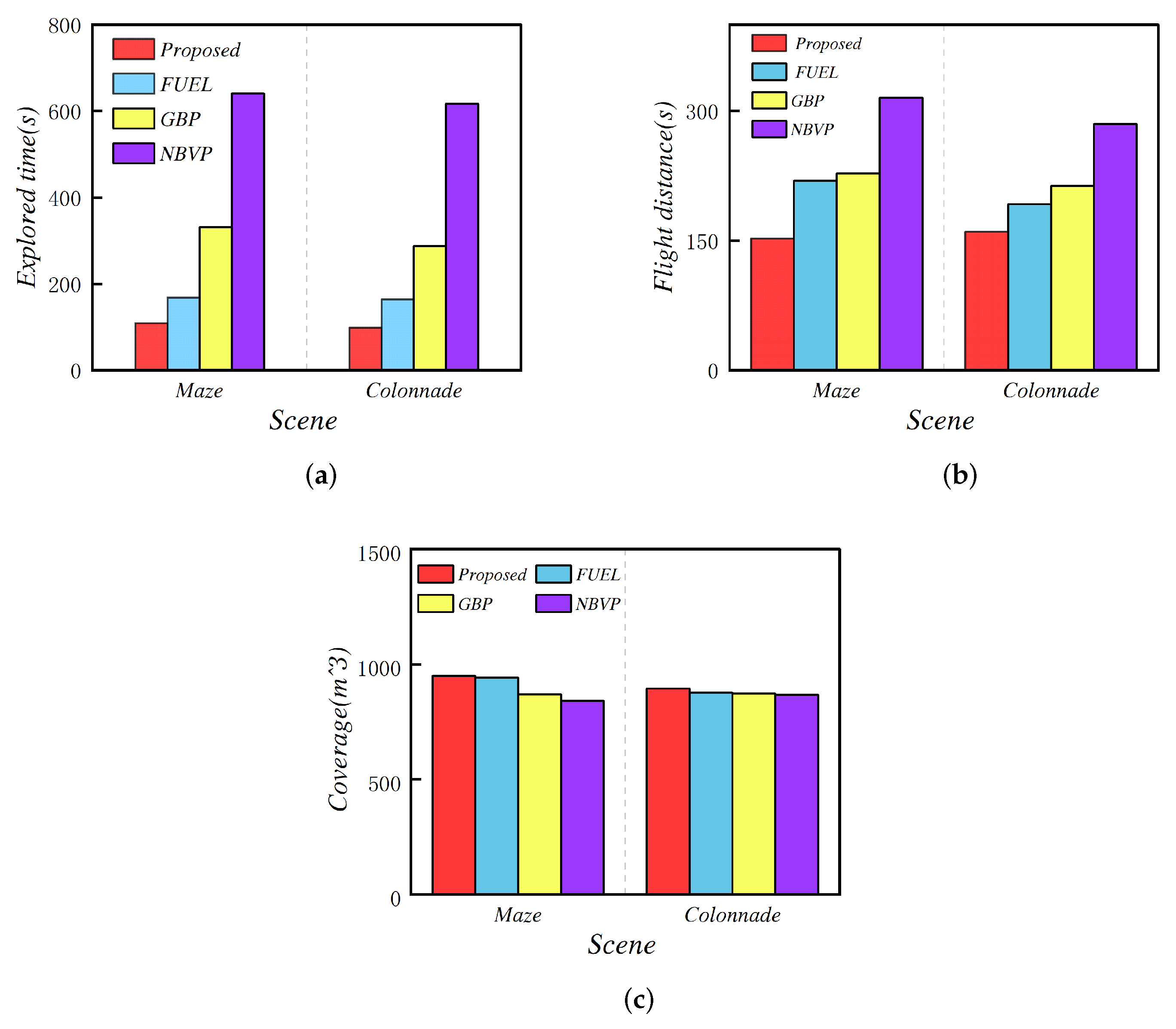
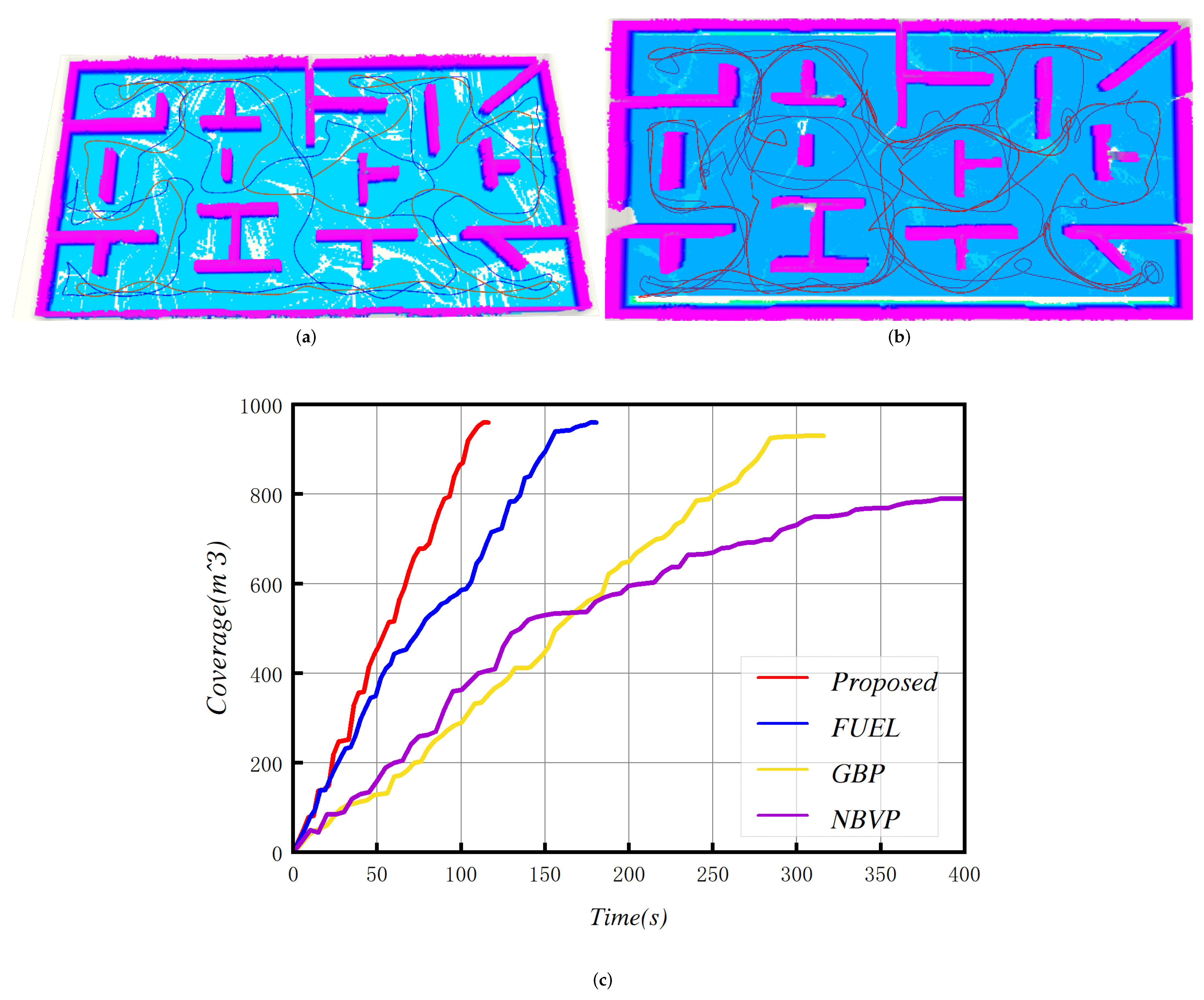
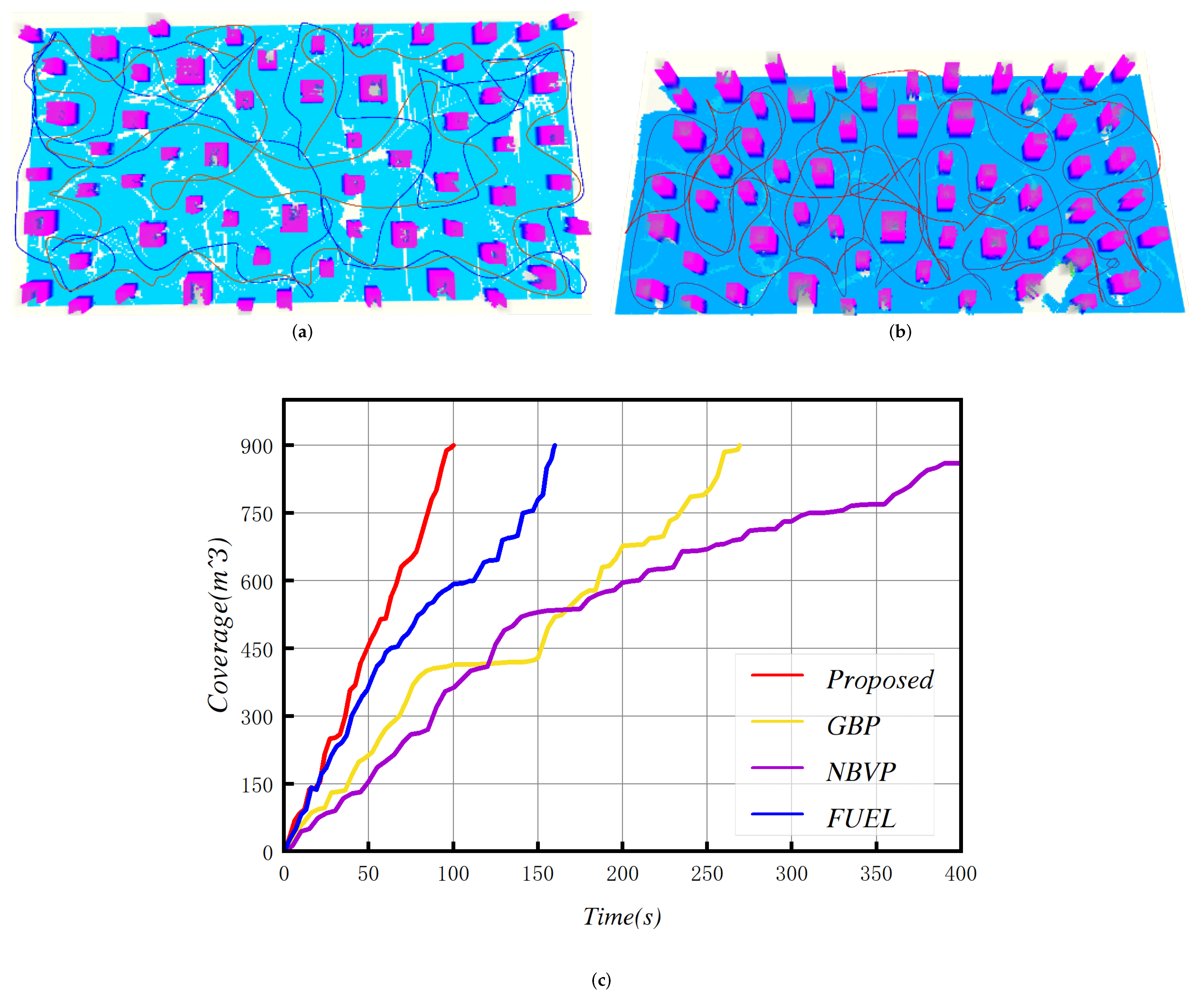
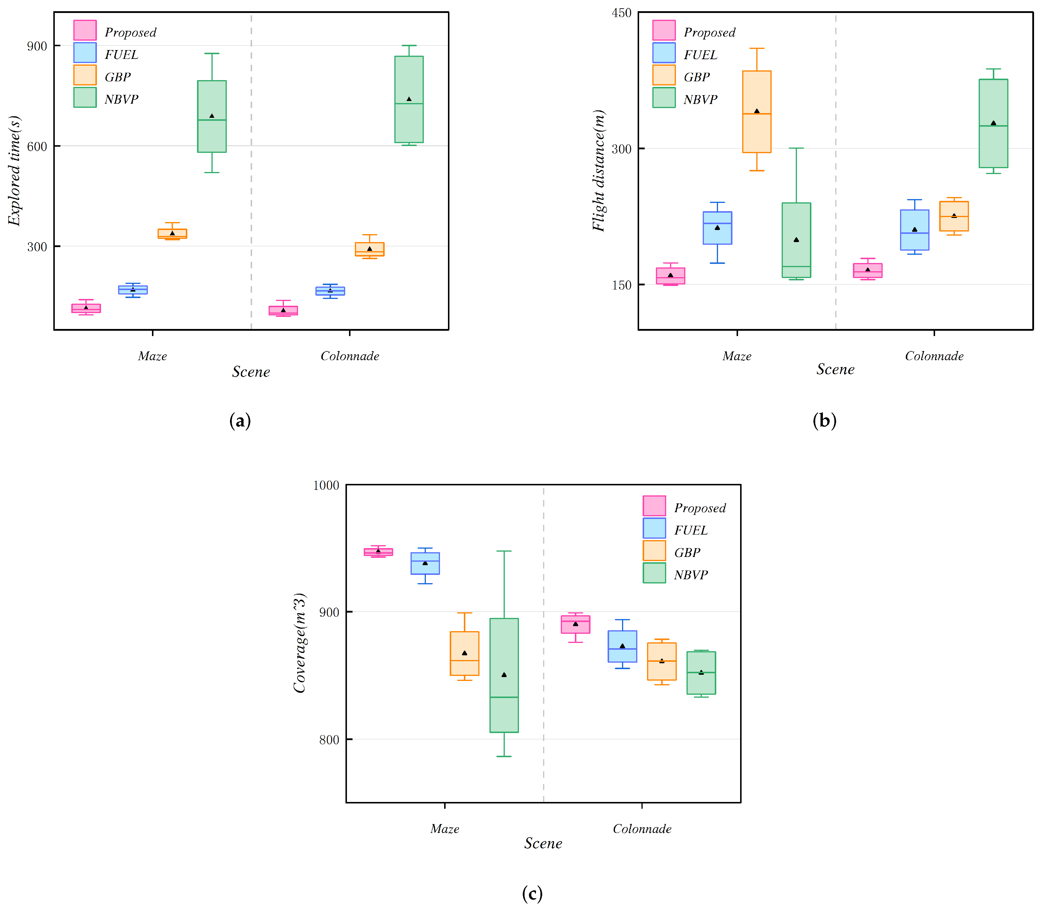
6.1. Benchmark Comparisons

To assess the proposed planner’s performance, comparative simulations were executed against three of the most advanced exploration algorithms (FUEL [16], GBP [28], and NBVP [6] across diverse environments. Each algorithm was tested in four independent trials per scenario, using the same initial setup for all trials. Furthermore, it should be specifically noted that all algorithms utilized the identical initial configuration for every experiment. All methods used common parameters: maximum linear velocity = 2.0 m / s , maximum angular velocity = 1.0 rad / s , and an exploration time limit of 1200 s (20 min). The algorithms were implemented in C++ using the ROS framework. Simulation experiments utilized the Gazebo/ROS platform and were executed on an Intel Core i7-12700K @ 3.8 GHz processor.
Maze Scenario: The exploration efficiencies of the four methods are compared within a maze environment measuring [ 32 × 15 × 2 ] m 3 . Experimental results are presented in Figure 7 and Figure 8 and Table 1. The experimental data reveal that the NBVP method took the longest time and had the greatest flight distance while exhibiting unstable exploration efficiency. By refining its frontier exploration strategy, GBP improved exploration efficiency, performing better than NBVP. As a result of effective, comprehensive coverage planning and time-minimizing path generation, both the proposed method and FUEL exhibited notable superiority over NBVP and GBP. While maintaining high coverage, they yield smoother actual flight paths, reduced time expenditure, and shorter overall path lengths. Furthermore, due to reduced back-and-forth movements and a more consistent planning approach, the proposed method achieved higher exploration efficiency than FUEL. Contrasted with FUEL, the proposed method exhibited a reduction of 23.4% in average flight time and a decrease of 27.1% in flight distance. Its exploration rate also showed near-linear progression.
Colonnade Scenario: The four methods were comparatively tested within a [ 30 × 15 × 2 ] m 3 colonnade environment, with results depicted in Figure 9 and Figure 10 and Table 1. The data indicate that, due to the reduced complexity of the scenario, the exploration time and flight distance for all four methods decreased compared to the previous scenario, but the method proposed in this paper still maintained a significant advantage in terms of flight time and flight distance. Compared to NBVP and GBP, the proposed method was 3 to 6 times faster on average. Compared to FUEL, it reduced exploration time by 9 % and flight distance by 12.5 % .

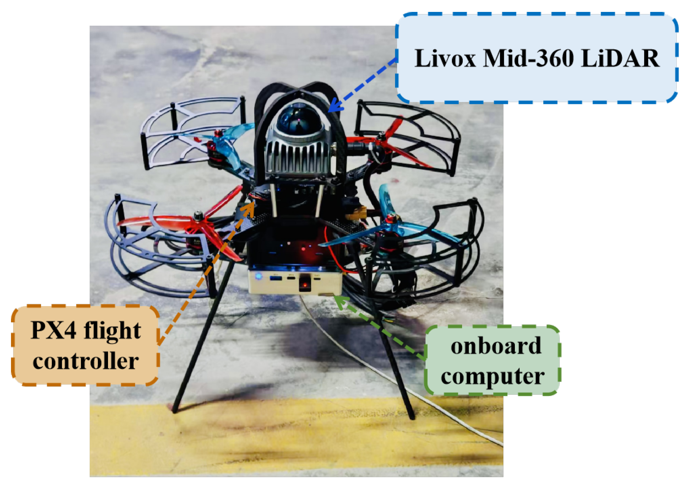
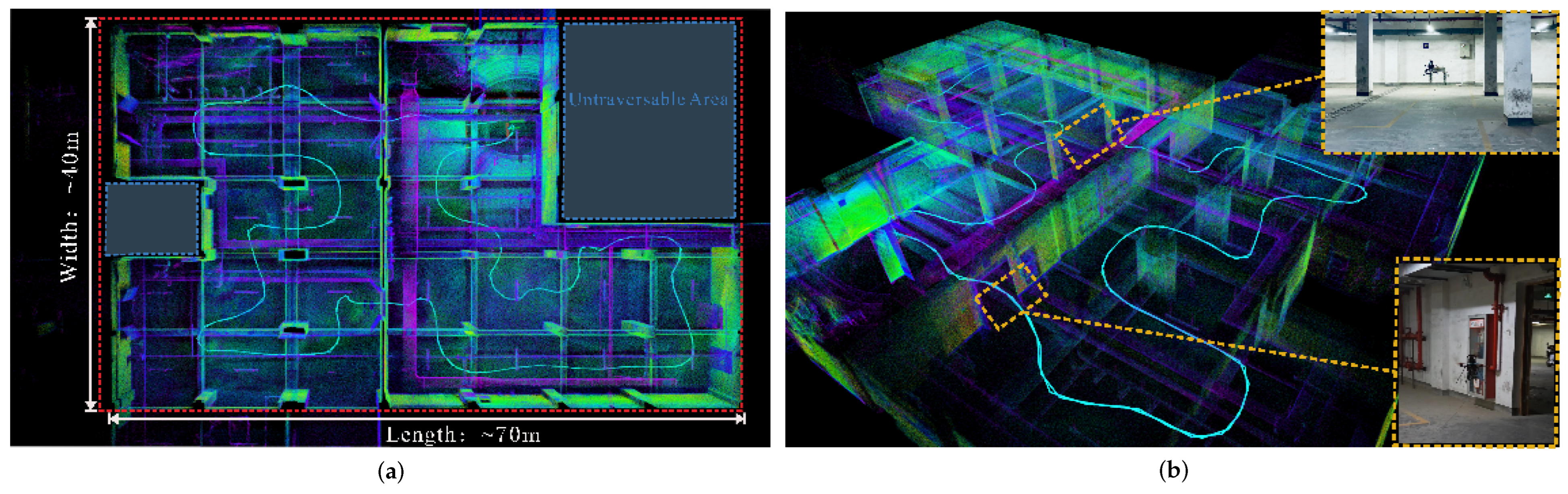
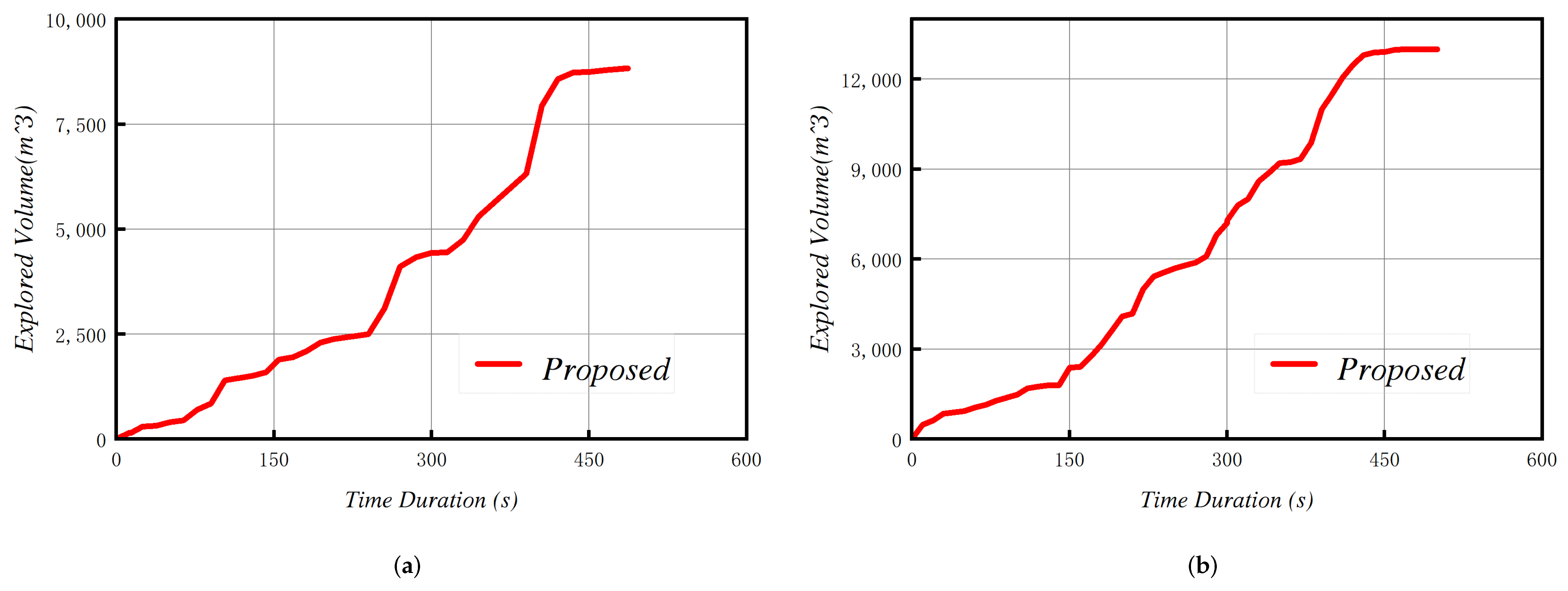
6.2. Physical Experiments

To further verify the proposed methodology, empirical validation was conducted through real-world flight trials utilizing a custom-built quadrotor unmanned aerial vehicle (UAV) in multiple types of complex environments. We constructed a LiDAR-based quadrotor UAV platform incorporating an NVIDIA Jetson Orin onboard computer (NVIDIA Corporation, Santa Clara, CA, USA), a Pixhawk 4 flight controller (Holybro, Hong Kong, China), and a Livox MID360 LiDAR (Livox Technology Co., Ltd., Shenzhen, China), illustrated in the Figure 11. Regarding localization and mapping, this study employs a tightly coupled framework integrating LiDAR point cloud data with the flight controller’s internal IMU. An enhanced FAST-LIO2 algorithm [61], optimized via dynamic point cloud filtering and multi-resolution map management [50], is utilized to realize high-accuracy, high-frequency real-time state estimation. To address sensor spatio-temporal synchronization, an offline calibration procedure was used to compensate for time offsets and extrinsic parameter errors between the LiDAR and IMU, ensuring robust multi-source data fusion. The trajectory tracking module features a Model Predictive Controller (MPC) [62] leveraging SE ( 3 ) manifold geometry. This MPC formulates a nonlinear optimization problem that constrains the UAV’s pose to the SE ( 3 ) Lie group, minimizing both pose tracking error and control energy expenditure. Combined with high-frequency state estimation, this approach significantly improves robustness against disturbances in GPS-denied environments and enhances real-time motion control responsiveness.
Firstly, we employed a quadrotor UAV to explore an extensive indoor underground parking facility to verify the efficacy of the proposed method in real-world settings. The target exploration zone measured [ 70 × 40 × 3.2 ] m 3 . The UAV utilized a Livox MID360 LiDAR sensor for the experiment. The statistics of the two experiments are listed in Table 2. Figure 12 illustrates the point cloud map built in real time along with the corresponding execution trajectory. Figure 13a depicts the progression of the explored volume over time. During this trial, the drone commenced its flight in an open area, proceeded into the structure to perform exploration, and ultimately navigated back to its origin. At approximately 200 s, the UAV concluded the primary exploration of the parking facility, causing the curve’s slope in Figure 13a to flatten. At approximately 340 s, the quadrotor UAV entered a space to the right and covered a large unknown area, leading to a steep increase in the curve’s slope. The exploration of the target environment was essentially finalized at approximately 450 s, bringing the procedure to a close. Figure 12 displays the physical experiment performed in the underground parking structure, showcasing two distinct perspectives of the online generated map and trajectory. The red frame represents the bounding box of the area to be explored, and the blue box indicates non-traversable areas. The findings indicate that throughout the entire exploration procedure, the proposed method demonstrated minimal repetitive exploration or back-and-forth planning movements.
Next, we employed a quadrotor UAV to explore a complex forest environment measuring [ 68 × 65 × 3 ] m 3 . For this trial, the UAV, outfitted with a Livox mid360 LiDAR sensor, accomplished the exploration task in 473 s, traversing a total flight distance of 303.5 m. The statistics of the two experiments are listed in Table 2. Figure 14 illustrates the acquired point cloud data and the flight path, while the statistical outcomes can be found in Figure 14b. In conclusion, the empirical results from both the simulated environment and two distinct physical settings confirm that our method can effectively and safely explore target areas under diverse conditions.

7. Conclusions and Future Work

In this study, we propose a Fast Autonomous Exploration Method (FAEM) designed to enhance the autonomous exploration capabilities of UAVs equipped with lidar sensors, particularly in large-scale unknown environments. Central to our method is ensuring occlusion-free visibility of frontier cells. This is achieved by generating viewpoints modeled as occlusion-free ellipsoids within defined geometric bounds. These ellipsoids utilize anisotropic volume calculation and dynamic principal axis adjustment, offering significant advantages over simpler spherical models, especially in asymmetric environments. Consequently, this approach yields high-quality viewpoints while maintaining computational efficiency.
Building upon efficient viewpoint generation, the FAEM employs a hierarchical exploration strategy. This strategy incorporates global optimization to identify an effective global trajectory that sequences high-information-gain viewpoints, thereby balancing exploration completeness with computational resource usage. The global exploration path generation involves a guided topo-kinodynamic search conducted on an incrementally constructed topological graph. This search produces multiple candidate paths that satisfy kinodynamic constraints and cover diverse topological structures. Subsequently, path-guided optimization, leveraging B-spline properties, refines the chosen path to reconcile global optimality with local path smoothness. Once the next global exploration target (viewpoint) is determined, local path planning proceeds based on this guidance. During local trajectory generation, a refinement stage samples prospective viewpoints near targeted frontier clusters for initial observation. An observation trajectory is then established through selected viewpoints to efficiently maximize frontier area coverage. Furthermore, to enhance flight smoothness and stability during execution, the method integrates dynamic starting point selection for replanning coupled with a dynamic path replanning strategy.
Similar to many contemporary approaches, this work currently assumes perfect self-localization and a static target environment. However, In practical environments, inaccuracies in state estimation may substantially impair exploration efficacy—potentially resulting in mission failure—while the presence of dynamic obstacles, which are prevalent in real-world settings, can lead to incomplete coverage. The trajectory energy consumption is minimized via B-spline optimization under kinodynamic constraints. However, as a heuristic approach, it provides energy-efficient solutions rather than globally optimal ones. This is aligned with observations in online path planning studies. Therefore, future work will focus on adapting the proposed framework for enhanced real-world applicability. Key directions include incorporating odometry drift compensation to improve robustness against localization uncertainty and designing effective dynamic obstacle perception and avoidance strategies. Additionally, we plan to extend this method to multi-UAV cooperative systems to support efficient and rapid exploration of large-scale complex outdoor environments.

Author Contributions

Conceptualization, X.Z. and E.Z.; methodology, X.Z. and S.W.; software, J.W.; validation, X.Z., J.W. and E.Z.; formal analysis, M.W., S.Z. and Z.F.; investigation, T.W.; resources, E.Z.; data curation, E.Z.; writing—original draft preparation, X.Z.; writing—review and editing, X.Z.; visualization, X.Z.; supervision, E.Z.; project administration, E.Z.; funding acquisition, E.Z. All authors have read and agreed to the published version of the manuscript.

Funding

This research received no external funding.

Institutional Review Board Statement

Not applicable.

Informed Consent Statement

Not applicable.

Data Availability Statement

The original contributions presented in the study are included in the article, further inquiries can be directed to the corresponding author.

Conflicts of Interest

The authors declare no conflicts of interest.

References

  1. Cieslewski, T.; Kaufmann, E.; Scaramuzza, D. Rapid exploration with multi-rotors: A frontier selection method for high speed flight. In Proceedings of the IEEE/RSJ International Conference on Intelligent Robots and Systems (IROS), Vancouver, BC, Canada, 24–28 September 2017; IEEE: Piscataway, NJ, USA, 2017; pp. 2135–2142. [Google Scholar]
  2. Han, D.; Jiang, H.; Wang, L.; Zhu, X.; Chen, Y.; Yu, Q. Collaborative task allocation and optimization solution for unmanned aerial vehicles in search and rescue. Drones 2024, 8, 138. [Google Scholar] [CrossRef]
  3. Zhang, C.; Zhou, W.; Qin, W.; Tang, W. A novel UAV path planning approach: Heuristic crossing search and rescue optimization algorithm. Expert Syst. Appl. 2023, 215, 119243. [Google Scholar] [CrossRef]
  4. Zhang, M.; Li, W.; Wang, M.; Li, S.; Li, B. Helicopter-UAVs search and rescue task allocation considering UAVs operating environment and performance. Comput. Ind. Eng. 2022, 167, 107994. [Google Scholar] [CrossRef]
  5. Faiz, T.I.; Vogiatzis, C.; Liu, J.; Noor-E-Alam, M. A robust optimization framework for two-echelon vehicle and UAV routing post-disaster humanitarian logistics operations. Networks 2024, 84, 200–219. [Google Scholar] [CrossRef]
  6. Liu, Y.; Vogiatzis, C.; Yoshida, R.; Morman, E. Solving reward-collecting problems with UAVs: A comparison of online optimization and Q-learning. J. Intell. Robot. Syst. 2022, 104, 35. [Google Scholar] [CrossRef]
  7. Schmid, L.; Pantic, M.; Khanna, R.; Ott, L.; Siegwart, R.; Nieto, J. An efficient sampling-based method for online informative path planning in unknown environments. IEEE Robot. Autom. Lett. 2020, 5, 1500–1507. [Google Scholar] [CrossRef]
  8. Qin, H.; Meng, Z.; Meng, W.; Chen, X.; Sun, H.; Lin, F.; Ang, M.H. Autonomous exploration and mapping system using heterogeneous uavs and ugvs in gps-denied environments. IEEE Trans. Veh. Technol. 2019, 68, 1339–1350. [Google Scholar] [CrossRef]
  9. Battulwar, R.; Winkelmaier, G.; Valencia, J.; Naghadehi, M.Z.; Peik, B.; Abbasi, B.; Parvin, B.; Sattarvand, J. A practical methodology for generating high-resolution 3d models of open-pit slopes using uavs: Flight path planning and optimization. Remote Sens. 2020, 12, 2283. [Google Scholar] [CrossRef]
  10. Petráček, P.; Krátký, V.; Petrlík, M.; Báča, T.; Kratochvíl, R.; Saska, M. Large-scale exploration of cave environments by unmanned aerial vehicles. IEEE Robot. Autom. Lett. 2021, 6, 7596–7603. [Google Scholar] [CrossRef]
  11. Bircher, A.; Kamel, M.; Alexis, K.; Oleynikova, H.; Siegwart, R. Receding horizon “next-best-view” planner for 3d exploration. In Proceedings of the 2016 IEEE International Conference on Robotics and Automation (ICRA), Stockholm, Sweden, 16–21 May 2016; IEEE: Piscataway, NJ, USA, 2016; pp. 1462–1468. [Google Scholar]
  12. Meng, Z.; Qin, H.; Chen, Z.; Chen, X.; Sun, H.; Lin, F.; Ang, M.H. A two-stage optimized next-view planning framework for 3-d unknown environment exploration, and structural reconstruction. IEEE Robot. Autom. Lett. 2017, 2, 1680–1687. [Google Scholar] [CrossRef]
  13. Dang, T.; Tranzatto, M.; Khattak, S.; Mascarich, F.; Alexis, K.; Hutter, M. Graph-based subterranean exploration path planning using aerial and legged robots. J. Field Robot. 2020, 37, 1363–1388. [Google Scholar] [CrossRef]
  14. Dharmadhikari, M.; Dang, T.; Solanka, L.; Loje, J.; Nguyen, H.; Khedekar, N.; Alexis, K. Motion primitives-based path planning for fast and agile exploration using aerial robots. In Proceedings of the 2020 IEEE International Conference on Robotics and Automation (ICRA), Paris, France, 31 May–31 August 2020; IEEE: Piscataway, NJ, USA, 2020; pp. 179–185. [Google Scholar]
  15. Bircher, A.; Kamel, M.; Alexis, K.; Oleynikova, H.; Siegwart, R. Receding horizon path planning for 3D exploration and surface inspection. Auton. Robot. 2018, 42, 291–306. [Google Scholar] [CrossRef]
  16. Duberg, D.; Jensfelt, P. UFOExplorer: Fast and scalable samplingbased exploration with a graph-based planning structure. IEEE Robot. Autom. Lett. 2022, 7, 2487–2494. [Google Scholar] [CrossRef]
  17. Zhang, X.; Chu, Y.; Liu, Y.; Zhang, X.; Zhuang, Y. A novel informative autonomous exploration strategy with uniform sampling for quadrotors. IEEE Trans. Ind. Electron. 2022, 69, 13131–13140. [Google Scholar] [CrossRef]
  18. Yamauchi, B. A frontier-based approach for autonomous exploration. In Proceedings of the 1997 IEEE International Symposium on Computational Intelligence in Robotics and Automation, Monterey, CA, USA, 10–11 July 1997; pp. 146–151. [Google Scholar]
  19. Zhao, Y.; Yan, L.; Xie, H.; Dai, J.; Wei, P. Autonomous exploration method for fast unknown environment mapping by using UAV equipped with limited FOV sensor. IEEE Trans. Ind. Electron. 2024, 71, 4933–4943. [Google Scholar] [CrossRef]
  20. Yu, J.; Shen, H.; Xu, J.; Zhang, T. ECHO: An efficient heuristic viewpoint determination method on frontier-based autonomous exploration for quadrotors. IEEE Robot. Autom. Lett. 2023, 8, 5047–5054. [Google Scholar] [CrossRef]
  21. Zhou, B.; Zhang, Y.; Chen, X.; Shen, S. Fuel: Fast uav exploration using incremental frontier structure and hierarchical planning. IEEE Robot. Autom. Lett. 2021, 6, 779–786. [Google Scholar] [CrossRef]
  22. Zhang, X.; Xu, X.; Liu, Y.; Wang, H.; Zhang, X.; Zhuang, Y. FGIP: A frontier-guided informative planner for UAV exploration and reconstruction. IEEE Trans. Ind. Inform. 2024, 20, 6155–6166. [Google Scholar] [CrossRef]
  23. Selin, M.; Tiger, M.; Duberg, D.; Heintz, F.; Jensfelt, P. Efficient autonomous exploration planning of large-scale 3-D environments. IEEE Robot. Autom. Lett. 2019, 4, 1699–1706. [Google Scholar] [CrossRef]
  24. Dai, A.; Papatheodorou, S.; Funk, N.; Tzoumanikas, D.; Leutenegger, S. Fast frontier-based information-driven autonomous exploration with an MAV. In Proceedings of the 2020 IEEE International Conference on Robotics and Automation, Paris, France, 31 May–31 August 2020; pp. 9570–9576. [Google Scholar]
  25. Wang, C.; Ma, H.; Chen, W.; Liu, L.; Meng, M.Q.-H. Efficient autonomous exploration with incrementally built topological map in 3D environments. IEEE Trans. Instrum. Meas. 2020, 69, 9853–9865. [Google Scholar] [CrossRef]
  26. Connolly, C. The determination of next best views. In Proceedings of the 1985 IEEE International Conference on Robotics and Automation, St. Louis, MO, USA, 25–28 March 1985; Volume 2, pp. 432–435. [Google Scholar]
  27. Ding, W.; Gao, W.; Wang, K.; Shen, S. An efficient b-spline-based kinodynamic replanning framework for quadrotors. IEEE Trans. Robot. 2019, 35, 1287–1306. [Google Scholar] [CrossRef]
  28. Papachristos, C.; Khattak, S.; Alexis, K. Uncertainty-aware receding horizon exploration and mapping using aerial robots. In Proceedings of the 2017 IEEE International Conference on Robotics and Automation (ICRA), Singapore, 29 May–3 June 2017; IEEE: Piscataway, NJ, USA, 2017; pp. 4568–4575. [Google Scholar]
  29. Dang, T.; Papachristos, C.; Alexis, K. Visual saliency-aware receding horizon autonomous exploration with application to aerial robotics. In Proceedings of the 2018 IEEE International Conference on Robotics and Automation (ICRA), Brisbane, Australia, 21–25 May 2018; IEEE: Piscataway, NJ, USA, 2018; pp. 2526–2533. [Google Scholar]
  30. Witting, C.; Fehr, M.; Ahnemann, R.B.; Oleynikova, H.; Siegwart, R. History-aware autonomous exploration in confined environments using mavs. In Proceedings of the 2018 IEEE/RSJ International Conference on Intelligent Robots and Systems (IROS), Madrid, Spain, 1–5 October 2018; IEEE: Piscataway, NJ, USA, 2018; pp. 1–9. [Google Scholar]
  31. Wang, C.; Zhu, D.; Li, T.; Meng, M.Q.-H.; de Silva, C.W. Efficient autonomous robotic exploration with semantic road map in indoor environments. IEEE Robot. Autom. Lett. 2019, 4, 2989–2996. [Google Scholar] [CrossRef]
  32. Dang, T.; Mascarich, F.; Khattak, S.; Papachristos, C.; Alexis, K. Graph-based path planning for autonomous robotic exploration in subterranean environments. In Proceedings of the 2019 IEEE/RSJ International Conference on Intelligent Robots and Systems (IROS), Macau, China, 3–8 November 2019; IEEE: Piscataway, NJ, USA, 2019; pp. 3105–3112. [Google Scholar]
  33. Keidar, M.; Kaminka, G.A. Efficient frontier detection for robot exploration. Int. J. Robot. Res. 2014, 33, 215–236. [Google Scholar] [CrossRef]
  34. Quin, P.; Nguyen, D.D.K.; Vu, T.L.; Alempijevic, A.; Paul, G. Approaches for efficiently detecting frontier cells in robotics exploration. Front. Robot. AI 2021, 8, 616470. [Google Scholar] [CrossRef]
  35. Quin, P.; Alempijevic, A.; Paul, G.; Liu, D. Expanding wavefront frontier detection: An approach for efficiently detecting frontier cells. In Proceedings of the 2014 Australasian Conference on Robotics and Automation, ACRA, Melbourne, Australia, 2–4 December 2014. [Google Scholar]
  36. Shen, S.; Michael, N.; Kumar, V. Autonomous indoor 3d exploration with a micro-aerial vehicle. In Proceedings of the 2012 IEEE International Conference on Robotics and Automation, Saint Paul, MN, USA, 14–18 May 2012; IEEE: Piscataway, NJ, USA, 2012; p. 915. [Google Scholar]
  37. Juliá, M.; Gil, A.; Reinoso, O. A comparison of path planning strategies for autonomous exploration and mapping of unknown environments. Auton. Robot. 2012, 33, 427–444. [Google Scholar] [CrossRef]
  38. Zhu, F.; Ren, Y.; Kong, F.; Wu, H.; Liang, S.; Chen, N.; Xu, W.; Zhang, F. Decentralized lidarinertial swarm odometry. arXiv 2022, arXiv:2209.06628. [Google Scholar]
  39. Wang, Z.; Zhou, X.; Xu, C.; Gao, F. Geometrically constrained trajectory optimization for multicopters. IEEE Trans. Robot. 2022, 38, 3259–3278. [Google Scholar] [CrossRef]
  40. Kong, F.; Liu, X.; Tang, B.; Lin, J.; Ren, Y.; Cai, Y.; Zhu, F.; Chen, N.; Zhang, F. Marsim: A light-weight point-realistic simulator for lidar-based UAVs. arXiv 2022, arXiv:2211.10716. [Google Scholar] [CrossRef]
  41. Zhu, H.; Cao, C.; Xia, Y.; Scherer, S.; Zhang, J.; Wang, W. DSVP: Dual-stage viewpoint planner for rapid exploration by dynamic expansion. In Proceedings of the 2021 IEEE/RSJ International Conference on Intelligent Robots and Systems, Prague, Czech Republic, 27 September–1 October 2021; pp. 7623–7630. [Google Scholar]
  42. Respall, V.M.; Devitt, D.; Fedorenko, R.; Klimchik, A. Fast sampling-based next-best-view exploration algorithm for a MAV. In Proceedings of the 2021 IEEE International Conference on Robotics and Automation (ICRA), Xi’an, China, 30 May–5 June 2021; pp. 89–95. [Google Scholar]
  43. Tao, Y.; Wu, Y.; Li, B.; Cladera, F.; Zhou, A.; Thakur, D.; Kumar, V. Seer: Safe efficient exploration for aerial robots using learning to predict information gain. In Proceedings of the 2023 IEEE International Conference on Robotics and Automation (ICRA), London, UK, 29 May–2 June 2023; pp. 1235–1241. [Google Scholar]
  44. Ratliff, N.; Zucker, M.; Bagnell, J.A.; Srinivasa, S. Chomp: Gradient optimization techniques for efficient motion planning. In Proceedings of the IEEE International Conference on Robotics and Automation, Kobe, Japan, 12–17 May 2009; pp. 489–494. [Google Scholar]
  45. Kalakrishnan, M.; Chitta, S.; Theodorou, E.; Pastor, P.; Schaal, S. STOMP: Stochastic trajectory optimization for motion planning. In Proceedings of the IEEE International Conference on Robotics and Automation, Shanghai, China, 9–13 May 2011; pp. 4569–4574. [Google Scholar]
  46. Oleynikova, H.; Burri, M.; Taylor, Z.; Nieto, J.; Siegwart, R.; Galceran, E. Continuous-time trajectory optimization for online UAV replanning. In Proceedings of the IEEE/RSJ International Conference on Intelligent Robots and Systems, Daejeon, Republic of Korea, 9–14 October 2016; pp. 5332–5339. [Google Scholar]
  47. Zucker, M.; Ratliff, N.; Dragan, A.D.; Pivtoraiko, M.; Klingensmith, M.; Dellin, C.M.; Bagnell, J.A.; Srinivasa, S.S. Chomp: Covariant hamiltonian optimization for motion planning. Int. J. Robot. Res. 2013, 32, 1164–1193. [Google Scholar] [CrossRef]
  48. Gao, F.; Lin, Y.; Shen, S. Gradient-based online safe trajectory generation for quadrotor flight in complex environments. In Proceedings of the 2011 IEEE/RSJ International Conference on Intelligent Robots and Systems (IROS), Vancouver, BC, Canada, 24–28 September 2017; pp. 3681–3688. [Google Scholar]
  49. Zhou, B.; Pan, J.; Gao, F.; Shen, S. Raptor: Robust and perception-aware trajectory replanning for quadrotor fast flight. arXiv 2020, arXiv:2007.03465. [Google Scholar] [CrossRef]
  50. Zhou, X.; Wang, Z.; Ye, H.; Xu, C.; Gao, F. EGO-Planner: An ESDF-Free Gradient-Based Local Planner for Quadrotors. IEEE Robot. Autom. Lett. 2021, 6, 478–485. [Google Scholar] [CrossRef]
  51. Xu, W.; Cai, Y.; He, D.; Lin, J.; Zhang, F. Fast-lio2: Fast direct lidar-inertial odometry. IEEE Trans. Robot. 2022, 38, 2053–2073. [Google Scholar] [CrossRef]
  52. Tang, B.; Ren, Y.; Zhu, F.; He, R.; Liang, S.; Kong, F.; Zhang, F. Bubble Explorer: Fast UAV Exploration in Large-Scale and Cluttered 3D-Environments Using Occlusion-Free Spheres. arXiv 2023, arXiv:2304.00852. [Google Scholar]
  53. Mueller, M.W.; Hehn, M.; D’Andrea, R. A computationally efficient motion primitive for quadrocopter trajectory generation. IEEE Trans. Robot. 2015, 31, 1294–1310. [Google Scholar] [CrossRef]
  54. Lin, S.; Kernighan, B.W. An effective heuristic algorithm for the traveling-salesman problem. Oper. Res. 1973, 21, 498–516. [Google Scholar] [CrossRef]
  55. Ding, W.; Gao, W.; Wang, K.; Shen, S. Trajectory replanning for quadrotors using kinodynamic search and elastic optimization. In Proceedings of the 2018 IEEE International Conference on Robotics and Automation (ICRA), Brisbane, Australia, 21–25 May 2018; IEEE: Piscataway, NJ, USA, 2018; pp. 7595–7602. [Google Scholar]
  56. Schmitzberger, E.; Bouchet, J.-L.; Dufaut, M.; Wolf, D.; Husson, R. Capture of homotopy classes with probabilistic road map. In Proceedings of the IEEE/RSJ International Conference on Intelligent Robots and Systems, Lausanne, Switzerland, 30 September–4 October 2002; IEEE: Piscataway, NJ, USA, 2002; Volume 3, pp. 2317–2322. [Google Scholar]
  57. Blochliger, F.; Fehr, M.; Dymczyk, M.; Schneider, T.; Siegwart, R. Topomap: Topological mapping and navigation based on visual slam maps. In Proceedings of the 2018 IEEE International Conference on Robotics and Automation (ICRA), Brisbane, Australia, 21–25 May 2018; IEEE: Piscataway, NJ, USA, 2018; pp. 1–9. [Google Scholar]
  58. Usenko, V.; Von Stumberg, L.; Pangercic, A.; Cremers, D. Real-time trajectory replanning for MAVs using uniform B-splines and a 3D circular buffer. In Proceedings of the 2017 IEEE/RSJ International Conference on Intelligent Robots and Systems (IROS), Vancouver, BC, Canada, 24–28 September 2017; pp. 215–222. [Google Scholar]
  59. Simeon, T.; Laumond, J.-P.; Nissoux, C. Visibility-based probabilistic roadmaps for motion planning. Adv. Robot. 2000, 14, 477–493. [Google Scholar] [CrossRef]
  60. Ren, Y.; Zhu, F.; Liu, W.; Wang, Z.; Lin, Y.; Gao, F.; Zhang, F. Bubble Planner: Planning High-speed Smooth Quadrotor Trajectories using Receding Corridors. In Proceedings of the 2022 IEEE/RSJ International Conference on Intelligent Robots and Systems (IROS), Kyoto, Japan, 23–27 October 2022; pp. 6332–6339. [Google Scholar] [CrossRef]
  61. Tordesillas, J.; Lopez, B.T.; How, J.P. Faster: Fast and safe trajectory planner for flights in unknown environments. In Proceedings of the 2019 IEEE/RSJ International Conference on Intelligent Robots and Systems (IROS), Macau, China, 3–8 November 2019; IEEE: Piscataway, NJ, USA, 2019; pp. 1934–1940. [Google Scholar]
  62. Zhu, F.; Ren, Y.; Zhang, F. Robust realtime lidar-inertial initialization. In Proceedings of the 2022 IEEE/RSJ International Conference on Intelligent Robots and Systems (IROS), Kyoto, Japan, 23–27 October 2022; IEEE: Piscataway, NJ, USA, 2022; pp. 3948–3955. [Google Scholar]
Figure 1. The proposed autonomous exploration framework. Following SLAM updates, the local 3D grid map enables frontier detection, clustering, and topological roadmap updates. Subsequently, the framework executes sequential stages: global planning, local trajectory planning, adaptive dynamic replanning, and trajectory optimization. Finally, the UAV follows the resulting trajectory to explore the unknown environment. The yellow frame indicates the dynamic replanning component.
Drones 09 00423 g001
Figure 2. The ellipsoidal coordinate system enables uniform sampling of viewpoints on the ellipsoid surface. Blue points denote candidate viewpoints in free space, while brown boxes represent frontier cells within the ellipsoid awaiting exploration.
Drones 09 00423 g002
Figure 3. Illustration of the viewpoint generation process. (Left) Candidate ellipsoid centers are generated via uniform downsampling. (Middle) The ellipsoid with the maximum volume is selected, a viewpoint is generated from it, and the candidate centers covered by this viewpoint are removed. (Right) The procedure repeats for the remaining candidate centers to yield the final set of viewpoints.
Drones 09 00423 g003
Figure 4. Illustration of the guided kinodynamic path search method. Yellow curves represent motion primitives. The brown gridded path indicates the initial geometric path planned by the A* algorithm. The green path is the pruned guiding path derived from the A* result. The red curve shows the final kinodynamic trajectory.
Drones 09 00423 g004
Figure 5. The proposed replanning framework is illustrated as follows: (a) When a planned trajectory segment (shown in brown) collides with an obstacle, it initiates the generation of a topological roadmap within a local bounding box (as detailed in Section 4.1). (b) The optimization of the guiding geometric path involves parallel path extraction, shortening, and pruning. Comparative analysis reveals that although the red trajectory is shorter than the blue trajectory, the corresponding trajectory of the red path shows greater irregularities near the start and end points because of sharp turns.
Drones 09 00423 g005
Figure 6. The construction of the topological roadmap is illustrated, with red nodes symbolizing Pioneer nodes and green nodes symbolizing Edge nodes. Subfigures (ac) illustrate the strategic placement of Pioneer nodes to encompass distinct spatial regions, alongside the integration of Edge nodes (connectors) to facilitate connections between Pioneer nodes. Subfigure (d) exhibits the substitution of an existing connector with a novel one to minimize connection distance. Subfigure (e) visualizes: the red and black trajectories are categorized within the same UVD class, whereas the orange trajectory represents a unique category.
Drones 09 00423 g006
Figure 7. (ac) represent the average exploration time, average flight distance, and average coverage, respectively, based on the results presented in Table 1.
Drones 09 00423 g007
Figure 8. Benchmark comparison of experimental results in indoor scenarios. (a,b) Comparison of flight trajectories in the maze scenario for the developed framework (red), FUEL (blue), GBP (yellow), and NBVP (purple). (c) Comparison of exploration progress over time for the four methods in the maze scenario.
Drones 09 00423 g008
Figure 9. Benchmark comparison of experimental results in the colonnade scenario. (a,b) Comparison of flight trajectories in the colonnade scenario for the developed framework (red), FUEL (blue), GBP (yellow), and NBVP (purple). (c) Comparison of exploration progress over time for the four methods in the colonnade scenario.
Drones 09 00423 g009
Figure 10. (ac) respectively show the distribution of Exploration time, Flight distance, and Coverage from the experimental results (presented in Table 1) for the four methods across two different scenarios.
Drones 09 00423 g010
Figure 11. The quadrotor platform used in real-world experiments: a quadrotor drone equipped with an NVIDIA Jetson Orin onboard computer, a Livox Mid-360 LiDAR sensor, and a Pixhawk 4 flight controller.
Drones 09 00423 g011
Figure 12. The real-world exploration in an underground garage. (a,b): A field test carried out in an underground garage illustrates two views of the online-generated quadrotor UAV’s execution trajectory. The red frame delineates the bounding volume of the target exploration zone, while the blue frame identifies regions classified as non-traversable.
Drones 09 00423 g012
Figure 13. Variation of explored volume over time in different real-world scenarios. (a) represents the results from the underground parking garage experiment; (b) represents the results from the forest experiment.
Drones 09 00423 g013
Figure 14. The real-world exploration in a forest. (a,b): A field test performed in a forest setting presents two perspectives of the online-generated the UAV’s execution trajectory. The yellow and red frame delineates the bounding volume of the target exploration region. Owing to the LiDAR’s extended sensing range, areas outside this specified volume were also captured in the map.
Drones 09 00423 g014
Table 1. Exploration Statistic In The Two Scenarios.
SceneMethodExploration Time (s)Flight Distance (m)Coverage (m3)
AvgStdMaxMinAvgStdMaxMinAvgStdMaxMin
MazeProposed108.64.8123.2105152.410173.8149.2945.53.2952943.5
FUEL168.47.3177.3157.4219.411.2237.4215.2942.70.9953.1937.1
GBP331.111.1370.4327.52285.6248.5224.8869.311.5899.2853.7
NBVP640.5172.3876.5520.7315.482.6410.3275.3841.586.7947.7786.4
ColonnadeProposed98.71.1107.296.4160.26.8170.2155.4894.52.3899.7890.4
FUEL164.46.2173.4154.3192.48.7243.4183.4876.21.3893.8865.3
GBP287.220.3334.7263.7213.442.7245.7204.4872.417.8878.4842.5
NBVP617.5168.4900.4601.7284.932.4387.4272.4867.278.3869.7837.2
Table 2. The statistics of two real-world experiments.
SceneExploration Time (s)Flight Distance (m)Coverage (m3)
underground
garage
461451.68957
forest473303.513,042
Disclaimer/Publisher’s Note: The statements, opinions and data contained in all publications are solely those of the individual author(s) and contributor(s) and not of MDPI and/or the editor(s). MDPI and/or the editor(s) disclaim responsibility for any injury to people or property resulting from any ideas, methods, instructions or products referred to in the content.

