Article

Aerodynamic Optimization Design of an Orthogonal Octo-Rotor UAV in a Hovering State

School of Mechanical Engineering and Automation, Fuzhou University, Fuzhou 350116, China
*
Author to whom correspondence should be addressed.
Drones 2025, 9(4), 257; https://doi.org/10.3390/drones9040257
Submission received: 10 February 2025 / Revised: 21 March 2025 / Accepted: 25 March 2025 / Published: 27 March 2025
(This article belongs to the Special Issue Optimal Design, Dynamics, and Navigation of Drones)

Abstract

:
This paper presents a novel orthogonal octo-rotor Unmanned Aerial Vehicle (UAV) and addresses the aerodynamics of the UAV with varied rotor spacing by both numerical simulations and experiments. Compared with the traditional planar multirotor UAV, this novel orthogonal octo-rotor UAV features a compact structure with four horizontal main rotors for stability and thrust and four vertical auxiliary rotors for lateral movement. Additionally, the attitude and translation dynamics are decoupled with easy manipulations. To obtain a better hover performance, the flow field and hover performance of the UAV were analyzed with rotor spacing ratios i = D/L ranging from 0.55 to 0.9 (i = 0.55, 0.59, 0.63, 0.67, 0.71, 0.77, 0.83, 0.90) and a rotor speed ranging from 1500 to 2300 RPM. The results showed that a rotor spacing ratio of i = 0.55 achieves a better hover efficiency, increasing hover efficiency by 11.27% at 2000 RPM, where the maximal thrust increment is 3.92% and the power consumption decreased by 5.68% at the same time. Computational Fluid Dynamics (CFD) simulations were further validated by streamlines and velocity distributions. It indicated that the rotor interference from the outflow was decreased with the rotor spacing while the increasing rotor speed aggravated the influence of the auxiliary rotor on the downwash airflow of the main rotor. The potential benefit of the rotor interference from the main rotor and the auxiliary rotor improved the hover efficiency of the orthogonal octo-rotor UAV with a higher thrust increment, which offers it the unique capability of resisting wind gusts or even rotor failure, which will be validated with more field flight tests.

1. Introduction

Unmanned Aerial Vehicles (UAVs) have obtained significant popularity in performing dull, dirty, and dangerous tasks without human intervention, making the study of their flight performance an attractive research area [1,2,3,4]. In extreme flight conditions, UAVs may require specific forces or torques to accomplish tasks, particularly when interacting with the environment. However, traditional planar UAVs are unable to generate the necessary forces or torques in hovering conditions without relying on external forces. This limitation poses significant challenges for aerial manipulation using UAVs. In traditional multi-rotor UAVs, all rotors operate in the same plane or parallel planes, resulting in only four degrees of freedom (DOF) being controllable. This configuration inherently makes the system underactuated [5,6]. Furthermore, the altitude of these traditional multi-rotor UAVs is coupled with their flight direction, which reduces their flexibility and stability. As a result, they struggle to operate effectively in narrow or complex environments [7].
The novel orthogonal octo-rotor UAV is characterized by a unique configuration of four horizontal main rotors and four vertical auxiliary rotors. One of the key advantages of this orthogonal octo-rotor design is the decoupling of rotational and translational dynamics. The four horizontal main rotors provide the primary thrust for vertical movement and stability, while the four vertical auxiliary rotors enable lateral movement. This configuration allows the UAV to control its translational motion (forward, backward, left, and right) independently of its rotational motion (roll, pitch, and yaw). The decoupling is achieved by the orthogonal arrangement of the rotors, which ensures that the control inputs for translation and rotation do not interfere with each other, enhancing the UAV’s maneuverability and stability.
Compared to traditional planar quadrotors and other octo-rotor UAVs, the orthogonal octo-rotor design offers several distinct advantages. First, the decoupled dynamics improve flight stability, especially during aggressive maneuvers or in turbulent conditions. Second, the orthogonal arrangement enhances loading capacity by distributing thrust more efficiently across the rotors with a higher payload. Third, the auxiliary rotors provide precise lateral control, which improves the UAV’s ability to navigate through narrow spaces with higher failure tolerance. However, the complexity of the rotor interference between the main rotor and the auxiliary rotor introduces new difficulties in terms of predicting aerodynamic performance in hover. Moreover, the interference is more sensitive to the rotor spacing, and the rotor interference is more pronounced compared with planar multirotor UAVs. This interference can lead to variations in thrust, power consumption, and overall flight efficiency. Therefore, more and more studies are focused on the effect of the aerodynamic interference and improvement of the performance of UAVs [8].
Recent studies concerning the multi-rotor UAV design have focused on optimizing aerodynamic performance and reducing interference between rotors. Barcelos et al. [9] used the potential flow method to investigate the aerodynamic differences between two quadrotor configurations: square and diamond, focusing on the interactions between rotors. Asher et al. [10] analyzed the aerodynamic performance of UAV rotor blades with varying shapes through numerical simulations, ultimately optimizing the blade edges based on pressure distribution and thrust. Misiorowski et al. [11] conducted detached-eddy simulations to study the aerodynamics of a quadcopter in forward flight for the ‘X’ and ‘+’ configurations. Ganesan et al. [12] analyzed the drag of bodies with varied surface geometric profiles, validating their findings through wind tunnel tests. Their results demonstrated that selecting an appropriate surface geometric profile can reduce UAV drag and enhance stability. Lopez et al. [13] employed the SA and k-omega turbulence models, along with the multiple reference frame (MRF) method in steady-state simulations, to predict lift coefficients of propellers at various rotational speeds. Wang et al. [14] conducted an experimental study to systematically evaluate how different mounting configurations influence the integrated aerodynamic and aeroacoustic performance of individual rotor systems. While Salazar et al. [15] addressed dynamic coupling in a conventional eight-rotor UAV through a nonlinear control method to enhance stability and positioning, our orthogonal octo-rotor design fundamentally reduces dynamic coupling via its decoupled rotor configuration. This structural innovation not only simplifies control requirements but also improves maneuverability and efficiency, achieving an increase in hover efficiency and a reduction in power consumption compared to traditional layouts. Frankenberg et al. [16] tested the ability of an octo-rotor UAV to detect interference during flight, concluding that an orthogonal thrust configuration is advantageous for mitigating rotor interference and facilitating path planning.
This study focuses on the hover performance of an orthogonal octo-rotor UAV, changing the rotor spacing of the main rotors to reduce downwash interference; the results are provided as an implication of the control method in the near future.

2. Theoretical Analysis

The symbols shown in the theoretical analysis are defined in Table 1.

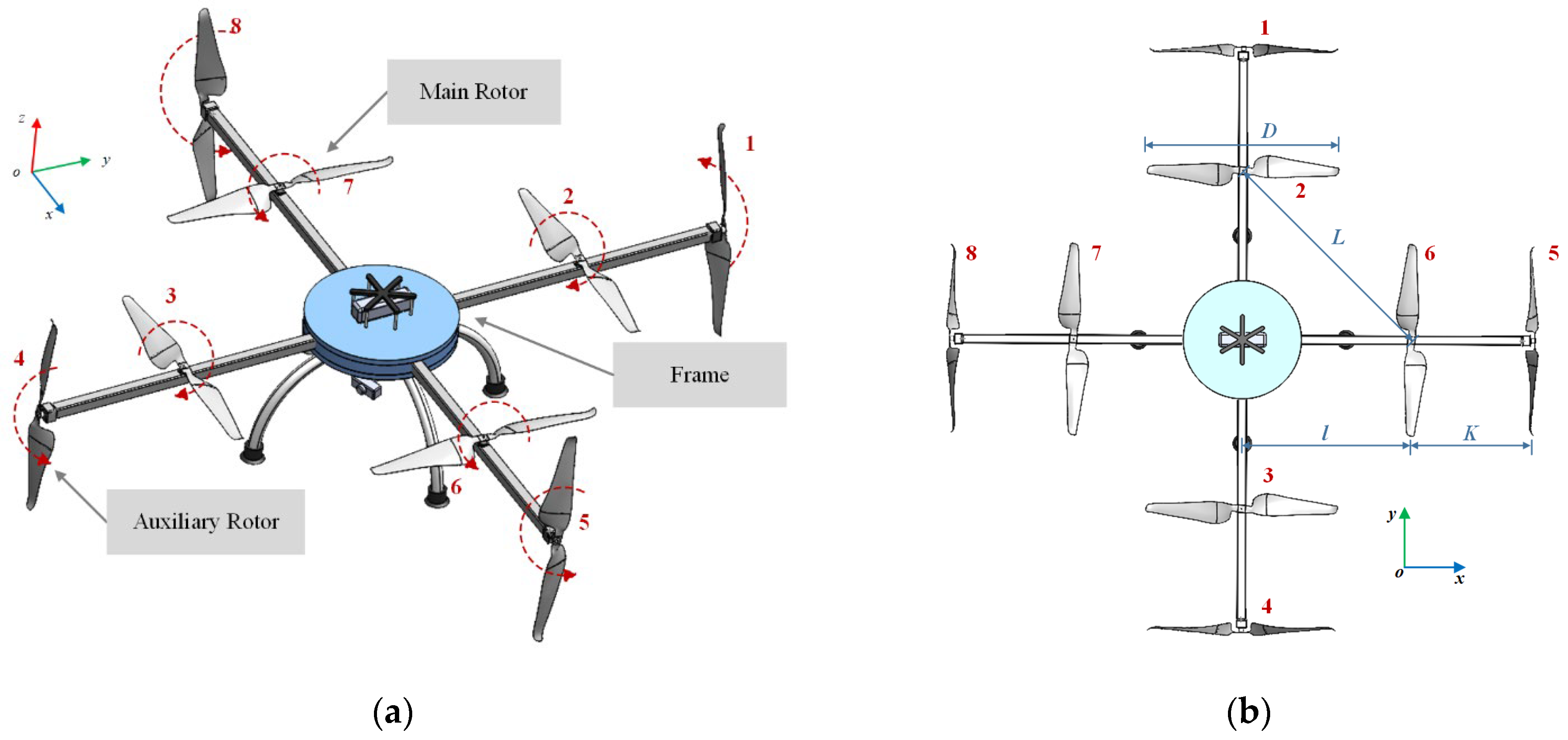
2.1. The Structure of the Orthogonal Octo-Rotor UAV
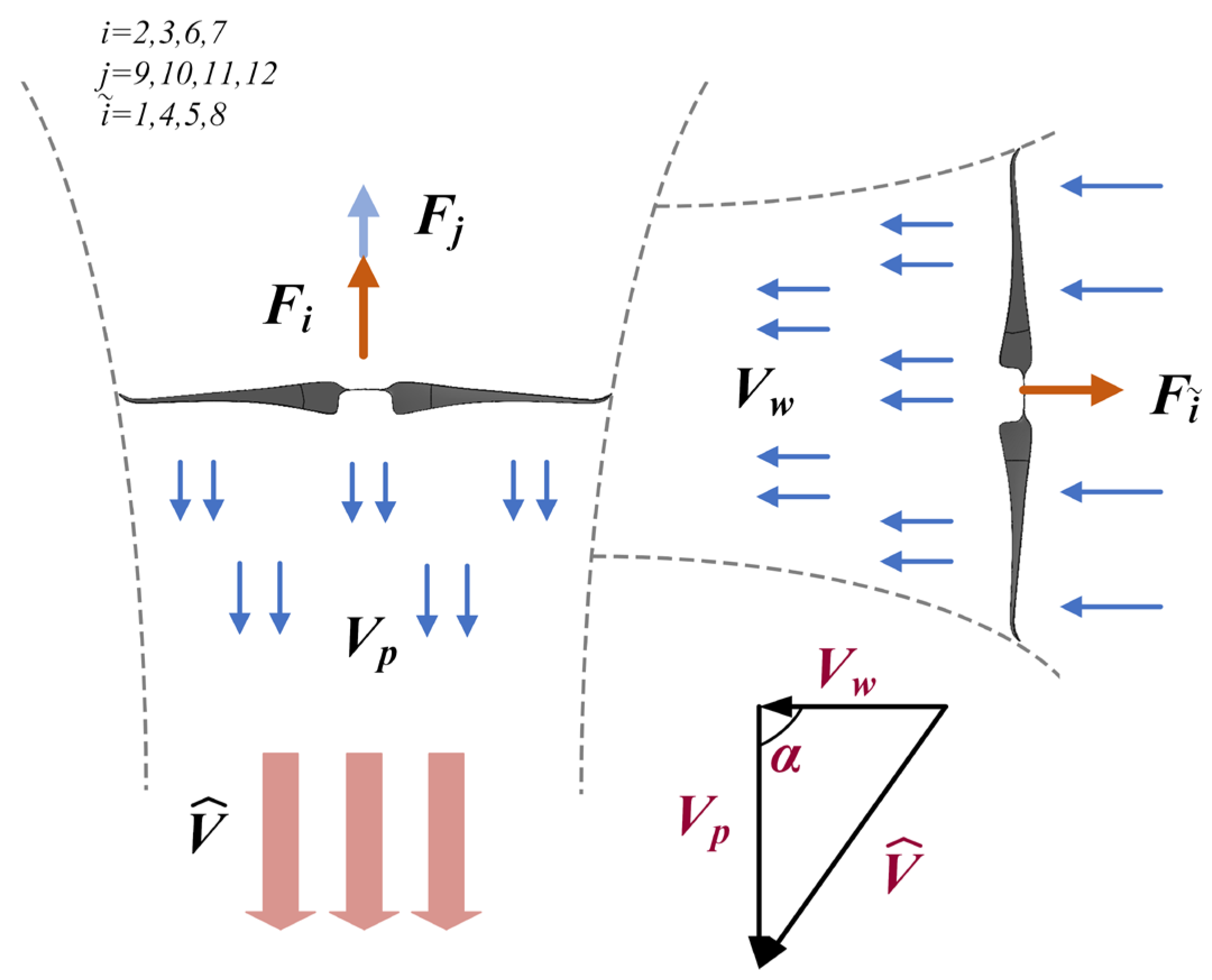
The structure of the orthogonal octo-rotor UAV proposed in this study is illustrated in Figure 1. The main rotors are traditional planar rotors labeled as 2, 3, 6, and 7; the auxiliary rotors labeled as 1, 4, 5, and 8 are arranged vertically. To maximize the thrust, the main rotors 2 and 3 and auxiliary rotors 1 and 8 rotate clockwise, whereas the main rotors 6 and 7 and auxiliary rotors 4 and 5 rotate counterclockwise. As shown in Figure 1b, D is the rotor diameter, L is the distance of the adjacent main rotor, and l is the distance of the main rotor and the vehicle center. K is the distance between the auxiliary rotor and the main rotor, and ω is the rotational speed.
The potential rotor interference between the main rotor and the auxiliary rotor is illustrated in Figure 2. Clearly, the rotor interference completely changes the original wake, and the downwash flow is deformed, which will definitely change the aerodynamic environment of the orthogonal octo-rotor UAV. This interference mainly includes: (1) Interference between adjacent main rotors. Both the inflow and the outflow generated by the adjacent main rotors lead to mutual interference. This effect intensifies as the rotor spacing decreases, potentially compromising vehicle stability and causing fluctuations in thrust and power consumption. (2) Interference between the auxiliary rotors. At a certain rotor spacing, the interference among auxiliary rotors can increase power consumption. Thus, identifying the optimal rotor spacing is critical to maximizing thrust efficiency and minimizing power consumption. (3) Another crucial factor affecting the orthogonal octo-rotor UAV is the interference between the auxiliary and the main rotor. The outflow from the auxiliary rotors collides with the inflow of the main rotors, reducing the main rotors’ performance. This interaction may be a critical factor in the overall aerodynamic efficiency of the UAV.
In Figure 2, v is the velocity of the downwash from the auxiliary rotor, μ is the resultant velocity, Ω is the rotor speed, and β is the azimuth angle.
The synthesis velocity μ at any point r on the main rotor can be expressed as:
μ = Ω r + v s i n β
The resultant velocity of the main rotor attains its peak values at β = 90° and β = 270°, with corresponding maximum observed in both thrust and velocity. Similarly, the resultant velocity and the thrust reach their minimum values at β = 0° and β = 180° due to the airflow separation on the rotor surface.

2.2. Force Analysis

Let G = i j k be the global coordinate system and B = i 1 j 1 k 1 represent the body coordinate system of the orthogonal octo-rotor UAV. The coordinates of the orthogonal octo-rotor are represented by q = ε σ R 6 , where ε = x y z is the position of the center of gravity of the orthogonal octo-rotor UAV relative to the global coordinate system, and σ = Ψ θ is the Euler angles of the orthogonal octo-rotor UAV (yaw, pitch, and roll angles), as illustrated in Figure 3.
From the body coordinate system B, we can see that:
F B = u x i 1 + u y j 1 + u z k ˙ 1
where
u x u y u z = F 5 F 8 F 1 F 4 F z + F 9 + F 10 + F 11 + F 12
with
F z = F 2 + F 3 + F 6 + F 7 ;       F i = k ω i 2 , i = 2 ,     3 ,     6 ,     7
where k > 0 is a constant, related to air density, rotor shape, and rotor diameter. F i is the thrust generated by the main rotor, and F j (∀j = 9, 10, 11, 12) is the additional thrust generated by the accelerated airflow of the auxiliary rotor, as illustrated in Figure 4.
As showed in Figure 4, the inflow of the main rotor interacts with the outflow of the auxiliary rotor, which will lead to thrust variation of the main rotor, and the total thrust F k = F i + F j can be expressed as [17]:
F k = 2 ρ A V ^ V p
where ρ ,   A ,   V p , and V w are the air density, the propeller area, the induced speed of the main rotor, and the induced speed of the auxiliary rotor, respectively.
According to Figure 4, the total induction velocity V ^ :
V ^ = V w cos α + V P 2 + V w sin α 2
where α  0     α     π 2 is the angle of the downwash flow from the auxiliary to the main rotor axis. Clearly, the direction of the induced velocity of the auxiliary rotor is vertical when α = 0 and it is horizontal when α = π 2 .
The translational force F G in the global coordinate system G is shown as:
F G = R F B
R is the attitude transformation matrix from the body coordinate system B to the global coordinate system G, where c ψ represents cos ψ and s ψ represents sin ψ .
R = c ψ c θ c ψ s θ s ϕ s ψ c ϕ c ψ s θ c ϕ + s ψ s ϕ s ψ c θ s ψ s θ s ϕ + c ψ c ϕ s ψ s θ c ϕ c ψ s ϕ s θ c θ s ϕ c θ c ϕ

2.3. Moment Analysis

Assume that the static torque generated by the counter-rotating pair can be neglected. The total torque M of an orthogonal octo-rotor UAV can be expressed as:
M = M ψ M θ M ϕ = M 2 + M 3 + M 6 + M 7 F 1 F 4 l + b u x F 5 F 8 l + b u y
where M i represents the torque of the i-th rotor motor, l is the distance between the main rotor and the center of mass, and b > 0 is a constant.

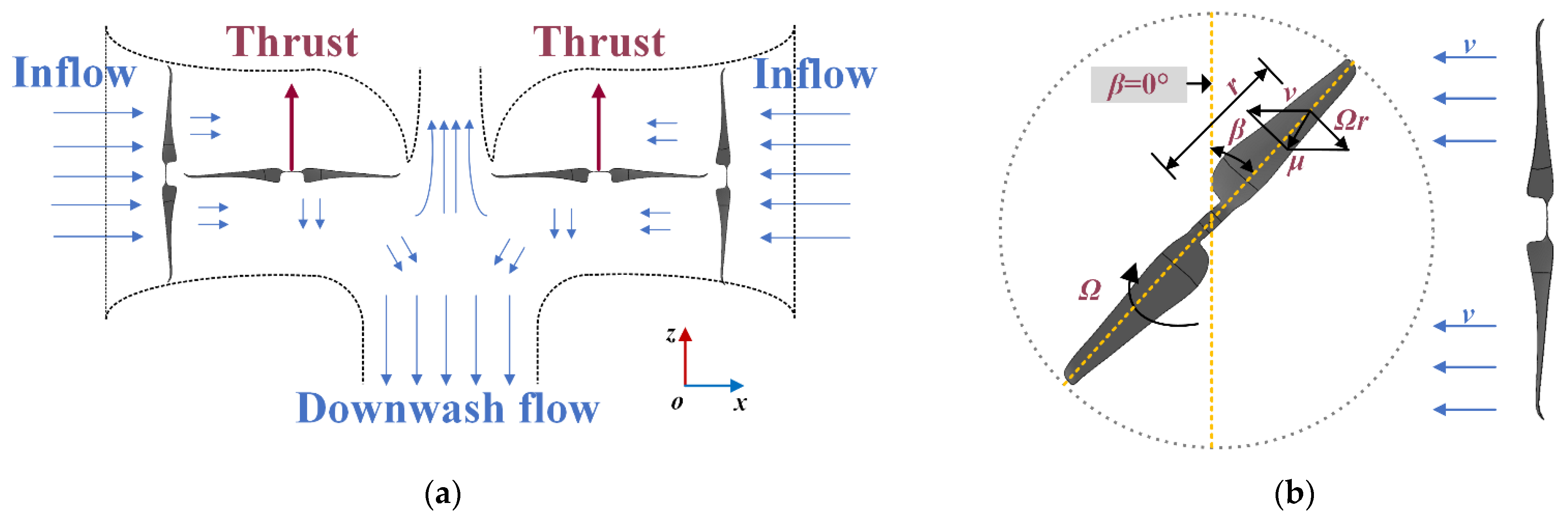
2.4. Aerodynamic Parameters

The rotor spacing ratio i is expressed non-dimensionally:
i = D L
The rotor diameter D is 400 mm. To prevent collision between adjacent main rotors, the minimum distance L = D. While increasing the distance between adjacent main rotors can mitigate airflow interference to some extent, an excessively large distance will extend the rotor arm length of the orthogonal octo-rotor UAV, leading to higher power consumption and reduced maneuverability. Consequently, the rotor spacing ratio i is set as 0.55, 0.59, 0.63, 0.67, 0.71, 0.77, 0.83, 0.90, and 0.95.
The figure of merit (FM) is presented to show the performance of the whole UAV, which is determined by both the thrust and power consumption directly. The definition of FM is as follows:
F M = C T 3 2 2 C P
The thrust coefficients and power coefficients C T and C P are defined as follows:
C T = T ρ A Ω 2 R 2     , C P = P ρ A Ω 3 R 3
where T is the thrust, P is the power consumption, ρ is the air density, A is the disk area, and R is the rotor radius. According to (11), a better hover efficiency comes from a higher figure of merit (FM), which is characterized by decreasing power consumption or increasing thrust. All equations were validated by experiments [10].

3. Simulations

3.1. Mesh Distribution

Figure 5 shows the mesh distribution. The computational domain includes a rotation region and a stationary region. To eliminate the ground effect, the UAV is located at the top of the domain. The static domain is a cylinder with a height of 6500 mm and a diameter of 4000 mm. The outer surfaces are set as pressure outlets. Given the structural complexity of the rotor, an unstructured grid partitioning method is employed to minimize computational errors, resulting in a final number of grid cells of approximately 21 million. The SST k-ω is selected as the turbulence model. Additionally, the transient calculations are performed using a second-order upwind discretization scheme. Table 2 shows the parameter values in the CFD simulation. Table 3 presents the mesh-independence study conducted for the rotational domains. It indicates that further increases in the number of meshes within the rotational domain have a negligible impact on the results when the mesh reaches 21 million. Consequently, Mesh 4 was selected for use in the subsequent simulations.

3.2. Simulation Results

Figure 6 illustrates the velocity contours of the UAV with different rotor spacings. It can be seen that the downwash flow changes significantly with different rotor spacings. At larger spacings, the outflow of the auxiliary rotors is more pronounced and extends further downward, indicating less interference between the main and auxiliary rotors. Furthermore, the downwash flow of the main rotors becomes more concentrated towards the center, suggesting increased airflow interference from the auxiliary rotors. This interference causes the downwash of the main rotor to contract more and diffuse outward, reducing the overall velocity of the downwash of the main rotors.
Figure 7 presents the velocity distribution, where the velocity magnitude of the bar is the same as in Figure 6. The main rotor induces a suction effect on the outflow of the auxiliary rotor, enhancing the downwash flow of the main rotor and potentially increasing the thrust of the UAV. The airflow below the UAV’s center separates and moves downward along the axis with the influence of the auxiliary rotor’s airflow. For a rotor spacing of i = 0.90, vortices form at the blade tips of the main rotor, leading to energy loss and an increase in power consumption, which affects the UAV’s stability [18]. The main rotor blades near the auxiliary rotor side exhibit strong upwash, leading to a harsh aerodynamic environment [19]. Thus, appropriate spacing between the main and auxiliary rotors obtains a better aerodynamic performance.
Figure 8 is the vorticity structure of the orthogonal octo-rotor UAV with different rotor spacings. The color scheme is the intensity, where the blue color indicates lower vorticity and red represents higher vorticity. The vortex structure of the inflow is solenoidal, and the maximal velocity is located at the rotor tip, which is similar to the original wake. However, the outflows of the rotors interact with each other. For the rotor spacing i = 0.9, the vortices between the main rotors are squeezed, leading to severe deformation of the vortices on the main rotor, which may decrease the aerodynamic performance. For the rotor spacing i = 0.55, the vortices of the orthogonal octo-rotor are intact, with less interference. In this case, the aerodynamic performance between the main rotors may be much improved.
Figure 9 shows the thrust variation of the main rotor, auxiliary rotor, and isolated single rotor at 2000 RPM for i = 0.55. It can be seen that the main rotor generates a maximum thrust of 330 g when β is 90 degrees and 270 degrees. The variation trend of the thrust is consistent with Equation (1). Clearly, the orthogonal octo-rotor UAV obtains a higher thrust than the equivalent single rotor without rotor interference, which indicates that the coupling of the outflow between the main and auxiliary rotors is beneficial for the thrust increment. The maximum thrust difference generated by the adjacent auxiliary rotors in a period is 7.01 g. This difference is due to the phase angle changes of the auxiliary rotors, which cause the thrust generated by the two adjacent auxiliary rotors to offset each other, helping the UAV to resist external interference. The phase angle changes of the auxiliary rotors are crucial for the thrust variation and the hover efficiency of the UAV. Thus, the performance may be improved with proper rotor interference between the main rotor and the auxiliary rotor with optimal rotor spacing to a certain extent.

4. Experiments

4.1. Experimental Setup

The rotor profile and test bench are shown in Figure 10.
According to Equation (11), the parameters include rotor speed, thrust, and power consumption with different rotor spacing ratio i. The distance l is 0.6D (240 mm). Furthermore, the orthogonal octo-rotor UAV was located at a height of 2 m to eliminate any ground effects [20,21].
The experimental procedure is as follows: (1) Power generation: a DC brushless motor (MSYS-LRK 195.03, Yuanhang Technology Electronics Co., Ltd., Guangzhou, China) is applied to drive the rotors; (2) Data acquisition: Rotor speed is measured by a Hall sensor (model: NJK-8001C, Wenzhou Henghui Electric Technology Co., Ltd., Wenzhou, China). The thrust is obtained by a thrust sensor (model: DYZ-101, Dayang Sensing System Engineering Co., Ltd., Bengbu, China). Current and voltage values are obtained from the DC power supply (Model: RS Pro IPS-3202, Dexin Technology Co., Ltd., Shenzhen, China).
For each rotor speed, data were collected at a sampling rate of 1000/s for a duration of four minutes, and the average values were calculated to mitigate the influence of unsteady effects. The experiments were conducted in an indoor facility at a temperature of 25 °C, a humidity of 53%, and an air pressure of 101.3 kPa. Furthermore, it was repeated three times to ensure the consistency and reliability of the results. Experimental parameters are shown in Table 4.

4.2. Experimental Results

As depicted in Figure 11, the thrust variation showed a similar tendency. The maximum thrust increased by 3.92% at 2000 RPM, with a rotor spacing ratio of i = 0.55. As the rotor spacing decreased, the thrust increment decreased along with the rotor spacing because of the strong rotor interference. Furthermore, there was a significant reduction in thrust at a higher rotor speed. This phenomenon can be attributed to two main factors: Firstly, the higher rotor speed increased the airflow disturbances of the main rotors, leading to a thrust loss. Secondly, the thrust increment at 2000 RPM obtained a proper interference, where the vortex was symmetrical without significant deformation. This was also proven by the pressure distribution presented in Figure 11. Normally, the pressure difference is related to thrust generation. For the main rotor spacing of i = 0.55, the pressure difference was maximum, resulting in a higher thrust performance. This highlights the significant impact of rotor spacing on the hover efficiency.
Figure 12 presents the power consumption characteristics relative to rotor speed. The experimental data reveal that all tested rotor spacing configurations exhibit lower power consumption compared to the i = 0.95 configuration. This finding confirms that reduced rotor spacing in orthogonal octo-rotor UAV systems leads to increased power demand. Notably, a significant power reduction of 6.41% was achieved at 1500 RPM, with a spacing ratio of i = 0.67, highlighting the substantial impact of optimal rotor spacing selection on enhancing the power efficiency of orthogonal octo-rotor UAVs.
The streamline distribution on the plane of Z = −0.2D is shown in Figure 12. Clearly, the reduced spacing enhanced the mutual interference between adjacent rotors, leading to turbulent flow separation and vortex shedding, which was consistent with the velocity streamline (Figure 7) and vorticity structure distribution (Figure 8). Considering that vortex deformation is related to the power consumption, the movement and the symmetry of the vortex may cause vibration with extra power. For i = 0.55, the vortex formation between adjacent rotors becomes more intact, leading to less power consumption. Compared with an isolated rotor, only a 5.68% increment was observed at 2000 RPM for i = 0.55. Therefore, the results suggest that increasing the main rotor spacing could potentially mitigate such aerodynamic interactions, thereby reducing power consumption and improving overall UAV performance.
Figure 13 shows the FM variation. The aerodynamic efficiency is characterized by FM with a higher thrust or less power consumption. In this case, there is an optimal configuration for the rotor spacing ratio i = 0.55 at 2000 RPM, which obtained a nearly 11.27% improvement in FM. Combined with the numerical simulations, the rotor interference from the main rotors and auxiliary rotors was balanced with higher thrust and lower power consumption. In contrast, a larger rotor spacing ratio (i ≥ 0.77) increased interference and suffered thrust losses with mechanical drag, especially for the minimal FM at i = 0.95. As expected, the maximum of FM was achieved at i = 0.55 and 2000 RPM. The proper spacing, by extending the rotor arm length, minimizes wake interactions between adjacent rotors and maintains sufficient airflow coupling to thrust increment. It was also proven by the velocity streamline, as shown in Figure 6, where the downwash patterns minimize energy dissipation and maximize pressure difference across rotor surfaces. Also, similar trade-offs between rotor interference and hover efficiency concerning FM with different spacings were illustrated in [19], which demonstrated the superiority of the orthogonal configuration again.
Figure 14 shows the thrust variation and the power variation of the orthogonal octo-rotor UAV compared with a traditional octo-rotor UAV and isolated rotor without interference. The experimental results demonstrate that the orthogonal octo-rotor configuration exhibits superior performance metrics for lower rotational speeds below 2000 RPM by achieving both higher thrust and lower power consumption. This enhanced performance can be attributed to two primary factors: (1) The orthogonal arrangement minimizes wake overlap between the main and auxiliary rotors, as illustrated by the streamline velocity contours in Figure 6e. The decreasing induced turbulence leads to lower power consumption, and (2) auxiliary rotors in the orthogonal configuration increase the inflow of the main rotors (Figure 4), thereby increasing the dynamic pressure difference and thrust. For a higher rotor speed beyond 2000 RPM, both configurations show an increase in power consumption. This phenomenon mainly results from intensified downwash airflow from the auxiliary rotors, which subsequently increases the overall power consumption. However, the orthogonal octo-rotor UAV maintains superior aerodynamic efficiency with a higher thrust increment to trade off the power increment. It was also validated in [9] that the decoupled configuration is beneficial to reduce interference in a multi-rotor UAV.

5. Conclusions

This study presented a novel orthogonal octo-rotor UAV with a better hover efficiency, implementing numerical simulations and experiments. The conclusions are summarized as follows:
1.
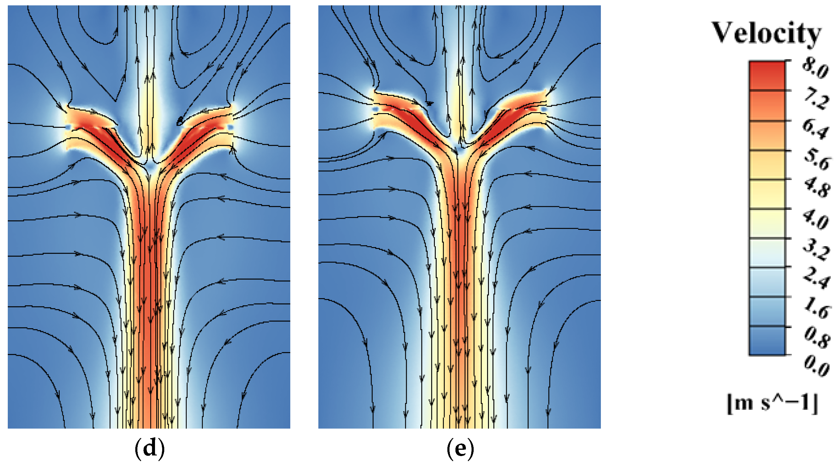
The outflow of the auxiliary rotors enhanced the thrust increment of the main rotors, with a maximum up to 3.92% at 2000 RPM for i = 0.55. Furthermore, the reduced rotor interference decreased the power consumption by 5.68%. This improvement was validated by the numerical simulations, where the velocity streamline of the downwash flow between the main rotor and the auxiliary rotor was intact, with symmetry distribution. It is interesting to note that the optimal rotor spacing ratio at i = 0.55 remained a perfect rotor interference, obtaining a thrust increment and the power decrement at the same time. This advantage was related to the orthogonal configuration with the decoupled dynamics that promoted this novel octorotor into a wider class for application compared to the traditional planar octorotors, such as the unique capability to resist wind gusts and a better failure tolerance in extreme conditions.
2.
The hover efficiency at 2000–2300 RPM decreased, with a sudden power increase, and the rotor interference accelerated the movement of the outflow; thereby, the vortex became irregular and unsymmetric. In this case, the orthogonal octorotor was suffering from thrust loss, leading to instabilities.
3.
The orthogonal arrangement not only has decoupled dynamics but also better hover efficiency with an optimal spacing ratio of i = 0.55 at 2000 RPM. The compact structure of the vertical auxiliary rotors allowed the UAV to fly in a narrow space with larger power loading from eight rotors and enhanced the maneuverability and stability of aggressive maneuvers. Further studies will involve the wind effect and more field flight tests in forward flight.

Author Contributions

Conceptualization, Y.L.; Software, H.Y. and J.H.; Formal analysis, H.Y., X.L. and Y.Z.; Writing—original draft, H.Y. and J.Q.; Writing—review and editing, Y.L.; Funding acquisition, Y.L. All authors have read and agreed to the published version of the manuscript.

Funding

This research was funded by the National Natural Science Foundation of China, grant number 52275095 and Fujian Provincial Industrial Robot Basic Components Technology Research and Development Center (2014H2004).

Data Availability Statement

The original contributions presented in the study are included in the article, further inquiries can be directed to the corresponding author.

Acknowledgments

We thank the Collaborative Innovation Center of High-End Equipment Manufacturing in Fujian Province of China for applying the experimental field.

Conflicts of Interest

The authors declare no conflict of interest.

References

  1. Mohsan, S.A.H.; Othman, N.Q.H.; Khan, M.A.; Amjad, H.; Żywiołek, J. A Comprehensive Review of Micro UAV Charging Techniques. Micromachines 2022, 13, 977. [Google Scholar] [CrossRef] [PubMed]
  2. Kim, J.S.A.; Gadsden, S.A.; Wilkerson, S.A. A comprehensive survey of control strategies for autonomous quadrotors. Can. J. Electr. Comput. Eng. 2019, 43, 3–16. [Google Scholar] [CrossRef]
  3. Liu, Z.; Liu, X.; Chen, J.; Fang, C. Altitude control for variable load quadrotor via learning rate based robust sliding mode controller. IEEE Access 2019, 7, 9736–9744. [Google Scholar] [CrossRef]
  4. Iscold, P.; Pereira, G.A.S.; Torres, L.A.B. Development of a Hand-Launched Small UAV for Ground Reconnaissance. IEEE Trans. Aerosp. Electron. Syst. 2010, 46, 335–348. [Google Scholar] [CrossRef]
  5. Mellinger, D.; Michael, N.; Kumar, V. Trajectory generation and control for precise aggressive maneuvers with quadrotors. Int. J. Robot. Res. 2012, 31, 664–674. [Google Scholar] [CrossRef]
  6. Ryll, M.; Bulthoff, H.H.; Giordano, P.R. Modeling and control of a quadrotor UAV with tilting propellers. In Proceedings of the IEEE International Conference on Robotics and Automation, Saint Paul, MN, USA, 14–18 May 2012; pp. 4606–4613. [Google Scholar] [CrossRef]
  7. Elfeky, M.; Elshafei, M.; Saif, A.W.A.; Al-Malki, M.F. Quadrotor helicopter with tilting rotors: Modeling and simulation. In Proceedings of the 2013 World Congress on Computer and Information Technology (WCCIT), Sousse, Tunisia, 22 June 2013. [Google Scholar] [CrossRef]
  8. Lei, Y.; Wang, H.D. Aerodynamic Performance of a Quadrotor MAV Considering the Horizontal Wind. IEEE Access 2020, 8, 109421–109428. [Google Scholar] [CrossRef]
  9. Barcelos, D.; Kolaei, A.; Bramesfeld, G. Aerodynamic Interactions of Quadrotor Configurations. J. Aircr. 2020, 57, 1074–1090. [Google Scholar] [CrossRef]
  10. Asher, P.K.; Deviparameswari, K.; Feonsa Antonitta, B.; Meenakshi, S.; Vijayanandh, R.; Senthil Kumar, M. Comparative Aerodynamic Performance Analysis on Modified UAV’s Propeller by Using CFD; Springer: Singapore, 2021; Volume 2, pp. 969–980. [Google Scholar] [CrossRef]
  11. Misiorowski, M.; Gandhi, F.; Oberai, A.A. Computational Study on Rotor Interactional Effects for a Quadcopter in Edgewise Flight. AIAA J. 2019, 57, 5309–5319. [Google Scholar] [CrossRef]
  12. Ganesan, S.; Esakki, B. Computational fluid dynamic analysis of an unmanned amphibious aerial vehicle for drag reduction. Int. J. Intell. Unmanned Syst. 2020, 8, 187–200. [Google Scholar] [CrossRef]
  13. Lopez, O.D.; Escobar, J.A.; Pérez, A.M. Computational Study of the Wake of a Quadcopter Propeller in Hover. In Proceedings of the 23rd AIAA Computational Fluid Dynamics Conference, Denver, CO, USA, 5 June 2017. [Google Scholar] [CrossRef]
  14. Wang, Z.; Henricks, Q.; Zhuang, M.; Pandey, A.; Sutkowy, M.; Harter, B.; McCrink, M.; Gregory, J. Impact of Rotor–Airframe Orientation on the Aerodynamic and Aeroacoustic Characteristics of Small Unmanned Aerial Systems. Drones 2019, 3, 56. [Google Scholar] [CrossRef]
  15. Salazar, S.; Romero, H.; Lozano, R.; Castillo, P. Modeling and Real-Time Stabilization of an Aircraft Having Eight Rotors. J. Intell. Robot. Syst. 2008, 54, 455–470. [Google Scholar] [CrossRef]
  16. Frankenberg, F.V.; Nokleby, S. Disturbance Rejection in Multi-Rotor Unmanned Aerial Vehicles Using a Novel Rotor Geometry. In Proceedings of the International Conference of Control, Dynamic Systems, and Robotics, Toronto, ON, Canada, 8 June 2017. [Google Scholar] [CrossRef]
  17. Guo, Y.Y.; Zhang, Y.M. A novel robust attitude control for quadrotor aircraft subject to actuator faults and wind gusts. IEEE/CAA J. Autom. Sin. 2018, 5, 292–300. [Google Scholar] [CrossRef]
  18. Wang, H.; Sun, W.; Zhao, C.; Zhang, S.; Han, J. Dynamic Modeling and Control for Tilt-Rotor UAV Based on 3D Flow Field Transient CFD. Drones 2022, 6, 338. [Google Scholar] [CrossRef]
  19. Lee, H.; Lee, D.J. Rotor interactional effects on aerodynamic and noise characteristics of a small multirotor unmanned aerial vehicle. Phys. Fluids 2020, 32, 47107. [Google Scholar] [CrossRef]
  20. Prothin, S.; Fernandez Escudero, C.; Doue, N.; Jardin, T. Aerodynamics of MAV rotors in ground and corner effect. Int. J. Micro Air Veh. 2019, 11, 1756829319861596. [Google Scholar] [CrossRef]
  21. Luo, Y.W.; Ai, T.F.; He, Y.H.; Zhao, Z.Z.; Xu, B.; Qian, Y.P.; Peng, J.; Zhang, Y.J. Aerodynamic analysis on unsteady characteristics of a ducted fan hovering in ceiling effect. Eng. Appl. Comput. Fluid Mech. 2023, 17, 1563–1584. [Google Scholar] [CrossRef]
Figure 1. Structure of the orthogonal octo-rotor UAV. (a) Rotor configuration. (b) Rotor spacing.
Drones 09 00257 g001
Figure 2. Rotor interference. (a) Flow field of the UAV. (b) Flow distribution of main rotor and auxiliary rotor.
Drones 09 00257 g002
Figure 3. Force vector of the orthogonal octo-rotor UAV.
Drones 09 00257 g003
Figure 4. Thrust distribution of main blade and auxiliary blade elements.
Drones 09 00257 g004
Figure 5. Computational domain.
Drones 09 00257 g005
Figure 6. Velocity contours at Ω = 2000 RPM. (a) i = 0.90; (b) i = 0.83; (c) i = 0.77; (d) i = 0.67; (e) i = 0.55.
Drones 09 00257 g006aDrones 09 00257 g006b
Figure 7. Velocity streamline. (a) i = 0.90; (b) i = 0.83; (c) i = 0.77; (d) i = 0.67; (e) i = 0.55.
Drones 09 00257 g007
Figure 8. Vorticity structure. (a) i = 0.90; (b) i = 0.83; (c) i = 0.77; (d) i = 0.67; (e) i = 0.55.
Drones 09 00257 g008
Figure 9. The thrust variation of the main rotor, auxiliary rotor, and single rotor at 2000 RPM for i = 0.55.
Drones 09 00257 g009
Figure 10. Experimental setup: (a) rotor profile; (b) test bench.
Drones 09 00257 g010
Figure 11. Thrust variation (compared with i = 0.95).
Drones 09 00257 g011
Figure 12. Power variation in hover mode (compared with i = 0.95).
Drones 09 00257 g012
Figure 13. FM variation (compared with i = 0.95).
Drones 09 00257 g013
Figure 14. Thrust and power variation.
Drones 09 00257 g014
Table 1. Nomenclature and definitions.
NomenclatureDefinitions
ARotor disk area
PPower consumption
RRotor radius
TThrust
SST k-ωShear Stress Transport k-omega model
DDiameter of the rotor
vDownwash velocity of the auxiliary rotor
ΩRotor speed
βAzimuth angle of the rotor
μDownwash velocity of the auxiliary rotor
Ψ, θ and ΦYaw, pitch, and roll angles
PMax and PMin (pa)Maximum and minimum pressures
C T Thrust coefficients
C P Power coefficients
Table 2. The parameter values in the CFD simulation.
ParametersValue Range
Rotor diameter (mm)400
Rotor speed (RPM)1500–2300
Rotor spacing ratio i0.55, 0.59, 0.63, 0.67, 0.71, 0.83, 0.90, 0.95
The dimensions of the cylinder(mm)Height: 6500, Diameter: 4500
The number of grid cellsApproximately 21 million
Table 3. Mesh independence.
NameMesh 1Mesh 2Mesh 3Mesh 4Mesh 5
No. grids (Million)68162125
PMax (Pa)154.26163.25167.59184.32186.56
Relative error of PMax16.4%11.0%9.2%1.7%-
PMin (Pa)−602.68−634.25−654.63−676.23−681.69
Relative error of PMin11.4%6.9%3.7%0.8%-
Table 4. Parameters.
ParametersValue
Rotor diameter (mm)400
Number of blades2
Weight0.015 kg
Material of bladesCarbon Fiber
Chord length (75% R)(0.4 − 0.62) × 105
Rotor solidity0.128
Rotor speed (RPM)1500–2300
Twist0
Rotor spacing ratio i0.55, 0.59, 0.63, 0.67, 0.71, 0.83, 0.90, 0.95
Disclaimer/Publisher’s Note: The statements, opinions and data contained in all publications are solely those of the individual author(s) and contributor(s) and not of MDPI and/or the editor(s). MDPI and/or the editor(s) disclaim responsibility for any injury to people or property resulting from any ideas, methods, instructions or products referred to in the content.

