1. Introduction
The rapid growth of Internet of Things (IoT) devices has driven the development of mobile edge computing (MEC) systems supported by unmanned aerial vehicles (UAVs), known as UAV–MEC systems. These systems address overload traffic requirements and improve communication quality [
1,
2,
3]. UAVs, with their low cost and high maneuverability, enable rapid deployment in areas lacking infrastructure. As airborne MEC nodes, they aggregate computing resources near ground users (GUs), reducing communication distances and enhancing quality of service (QoS) [
4,
5]. However, challenges remain in UAV–MEC applications, particularly in harsh wireless environments caused by ground obstacles.
To address these challenges, reconfigurable intelligent surface (RIS) have been introduced to improve energy efficiency and communication stability in UAV–MEC systems [
6,
7,
8]. Recent studies have explored combining UAV and RIS to optimize communication quality and energy consumption [
9,
10,
11]. However, traditional RIS only reflect signals, limiting their coverage. To overcome this, simultaneously transmitting and reflecting reconfigurable intelligent surface (STAR–RIS) have been proposed, enabling 360-degree full-space coverage and enhanced signal propagation [
12,
13,
14].
Unlike traditional RIS, GU signals can be reflected and transmitted simultaneously by various elements of STAR–RIS, achieving 360-degree full-space coverage. STAR–RIS provides additional degrees of freedom for signal propagation operations by simultaneously optimizing transmission and reflection coefficients, which can further enhance the performance of various wireless communication systems [
12,
13,
14]. Reference [
15] added STAR–RIS to UAV networks and, under the constraint of service quality requirements, jointly optimized the position and power allocation of UAVs and passive reflection/transmission beamforming of STAR–RIS to maximize the overall transmission rate. Reference [
16] proposed using STAR–RIS installed on UAVs to provide an improved signal-to-noise ratio for numerous GUs in remote or inaccessible areas. By optimizing the STAR–RIS phase shift matrix and UAV position, the overall data rate of GUs under UAV mobility constraints is maximized. Reference [
17] proposed a downlink system model for full-coverage STAR–RIS UAV secure communication, which achieves maximum energy efficiency by exploring joint resource allocation of the system. The above research proves that STAR–RIS can improve the communication performance of UAV systems. Therefore, we attempt to incorporate STAR–RIS into the UAV–assisted MEC network to provide better channel conditions for GU offloading. References [
18,
19] both propose a STAR–RIS–assisted UAV–MEC scheme that enables bidirectional task offloading to both ground base stations and UAVs, optimizing resource allocation, user scheduling, STAR–RIS beamforming, and UAV trajectory to maximize offloaded tasks while ensuring QoS. Extensive experimental analyses in these studies have demonstrated that STAR–RIS significantly outperforms conventional RIS in enhancing the service quality of UAV–assisted MEC systems. However, these studies do not fully address critical aspects such as long–term system stability and energy consumption under varying network conditions. Therefore, further research is needed to explore these challenges and develop more robust solutions for practical deployment.
In the STAR–RIS–assisted UAV–MEC network, GUs randomly generate tasks in each time slot, many of which cannot be processed immediately, forming task queues. Excessive queue lengths can delay task processing, degrading system performance and user experience. Thus, ensuring long–term queue stability for GUs and UAVs is a critical challenge. The Lyapunov method is a powerful framework for ensuring the long–term stable operation of dynamic systems. By constructing a Lyapunov function, it balances system utility and queue backlog, ensuring that task queues remain stable while optimizing performance metrics such as energy efficiency and task completion rates. Specifically, the drift-plus-penalty approach is employed to minimize system energy consumption while maintaining queue stability, which is critical for real-time applications in mobile edge computing (MEC) systems. Existing studies, such as [
20,
21], demonstrate the effectiveness of the Lyapunov method in UAV–assisted MEC systems. For instance, reference [
20] jointly optimizes computation offloading, resource allocation, and UAV trajectory to minimize energy consumption under random task arrivals, while [
21] minimizes the average weighted energy consumption of ground users (GUs) while ensuring data queue stability and UAV energy constraints. These works highlight that the Lyapunov method uniquely achieves long–term queue stability and improved quality of service (QoS), which is challenging for other optimization algorithms to accomplish. However, the above studies did not simultaneously consider the issue of task queue stability in STAR–RIS–assisted UAV–MEC networks. The stochastic optimization problem in MEC systems is challenging due to time coupling. Existing approaches, such as intelligent optimization algorithms [
22], convex optimization via CVX [
23], and reinforcement learning [
24], provide approximate solutions but suffer from high time complexity, making them unsuitable for real-time applications. Therefore, designing an efficient, low-complexity online optimization algorithm is essential.
This paper proposes an efficient and energy-saving resource allocation scheme for STAR–RIS assisted UAV–MEC networks. By considering the high-speed mobility of UAVs and the random arrival of GU tasks, our scheme ensures the long–term stability of both GU and UAV task queues. The key contributions of this work are summarized as follows:
A STAR–RIS–assisted UAV–MEC network model is established, where UAVs equipped with MEC servers provide MEC services to GUs. STAR–RIS dynamically switches between reflection and transmission modes based on the relative positions of UAVs, STAR–RIS, and GUs, improving channel conditions and offering flexible signal transmission methods. This overcomes the coverage limitations of traditional RIS, which can only reflect GU signals. Considering the random arrival of GU tasks and the need for long–term queue stability, this paper jointly optimizes GU transmit power, offloading time allocation, STAR–RIS phase shift, and UAV trajectory to minimize system energy consumption while ensuring queue stability.
To solve the long–term optimization problem, we introduce the Lyapunov method to transform it into deterministic subproblems for each time slot. A low-complexity alternating optimization algorithm is designed, which includes using the Lambert function to derive a closed-form solution for transmit power, applying Lagrange duality and the Karush–Kuhn–Tucker (KKT) conditions to optimize offloading time allocation, employing successive convex approximation (SCA) for low-complexity UAV trajectory planning, and solving the STAR–RIS phase shift using trigonometric inequalities.
The proposed algorithm is validated through extensive simulations, where it is compared with traditional RIS models and the chaotic particle swarm optimization (CPSO) algorithm. The results demonstrate that our approach outperforms benchmark methods in ensuring task queue stability and reducing energy consumption.
The rest of this paper is organized as follows:
Section 2 presents our STAR–RIS–assisted UAV–MEC network model and related optimization problems. In
Section 3, the process of transforming problems using Lyapunov theory and the algorithm of this paper are introduced.
Section 4 analyzes the effectiveness of the algorithm, and our simulation results are presented in
Section 5. Finally,
Section 6 provides a summary of this paper.
2. System Model and Problem Formulation
2.1. Overview
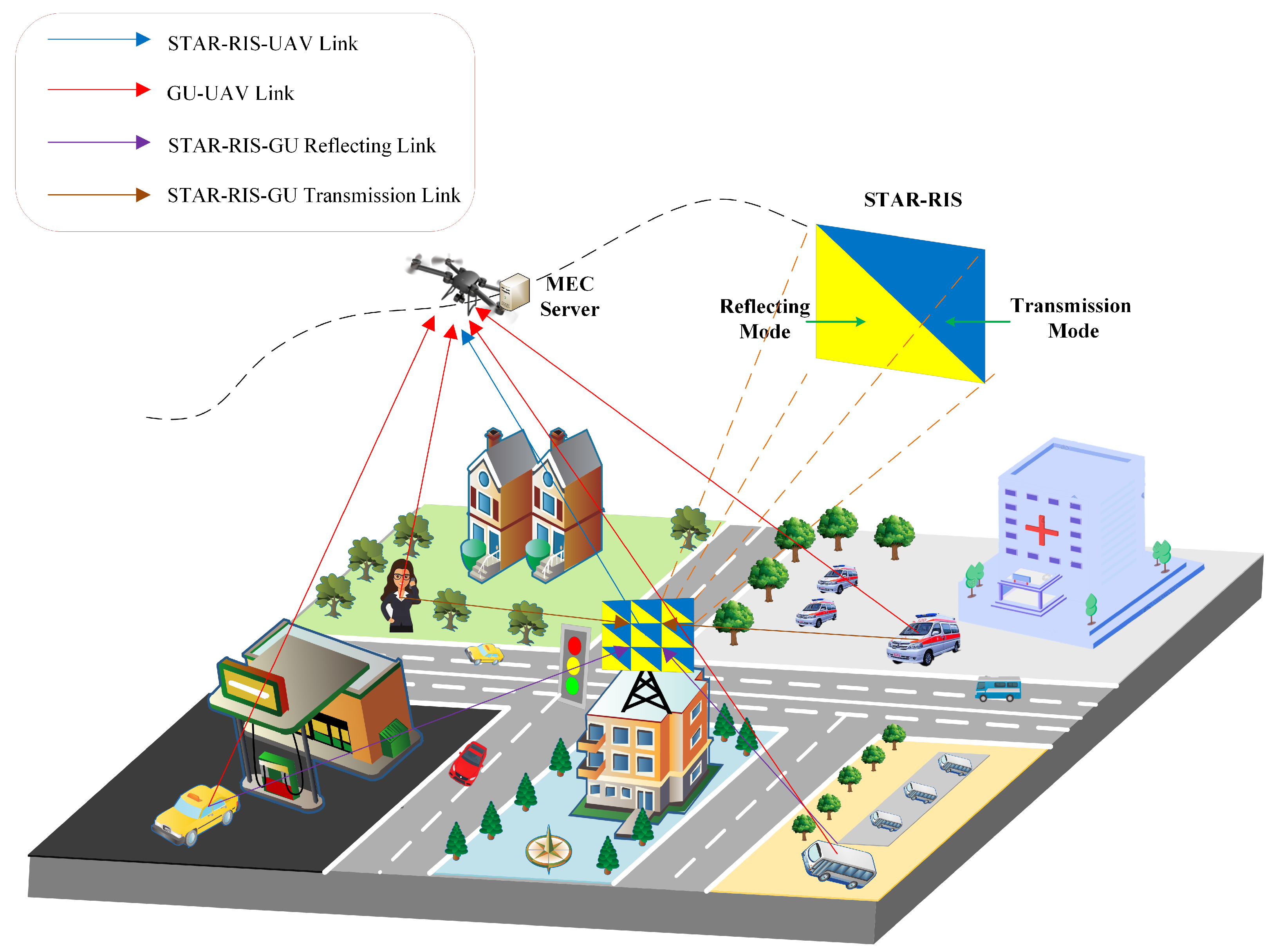
As illustrated in
Figure 1, a basic STAR–RIS–assisted UAV–MEC network consists of a computing-oriented UAV as the air MEC server, a STAR–RIS located in the center of the network, and
K single-antenna GUs which are randomly and uniformly distributed in the network. We assume that STAR–RIS consists of
elements, where
and
represent the number of horizontal and vertical elements of STAR–RIS, respectively. In addition, we define the set of all GUs as
, with GUs randomly and uniformly distributed in the urban area of the figure, and STAR–RIS located in the central area. Based on the relative positions of the UAV, STAR–RIS, and GUs, GUs can be divided into two categories. Specifically, GUs on the same side of STAR–RIS as the UAV are called reflective GUs, while GUs on different sides of STAR–RIS from the UAV are called transmission GUs. In addition, each GU will continuously generate computationally intensive tasks and offload a portion of them to the UAV’s MEC server through a partial offloading mode. And there are two signal links between the GU and UAV: direct link and reflection link or transmission link established through STAR–RIS. The signals from the above methods reach the receiver at the same time, and finally form the received signal.
As shown in
Figure 2, the system consists of three modules, namely the UAV module, GU module, and STAR–RIS module. The Software–Defined Networking (SDN) controller decouples the forwarding plane and control plane of network devices, managing network devices, orchestrating network services, and scheduling business traffic through controllers. The SDN controller deployed on the UAV collects real-time network environment information of the entire system and develops a resource allocation scheme in a programmed manner based on the collected information to improve system performance. Specifically, the system information (task generation volume, trajectory, queue length, etc.) of GUs, STAR–RIS, and the UAV is transmitted to the SDN controller, which quickly generates a reasonable resource allocation scheme by executing the algorithm described in this paper. Furthermore, the system transmits control decisions to the UAV, GUs, and STAR–RIS through the communication units of each module. In this process, GUs, upon receiving control commands from the SDN controller, offload tasks to the UAV through their communication units. The UAV, after receiving control commands from the SDN controller, accepts the offloaded tasks through its communication unit and adjusts its flight trajectory via its flight control unit. Simultaneously, STAR–RIS, upon receiving control instructions from the SDN controller, adjusts its mode and phase through its control unit. By reflecting or transmitting GU signals, STAR–RIS improves the channel conditions between GUs and the UAV. These three modules work collaboratively to effectively execute control decisions and allocate resources efficiently and reasonably.
The UAV flies over GUs during the flight cycle T to provide MEC services. The total service duration T is divided into N equal time slots, represented by , with each time slot having a size of . The value of is small enough to assume that the UAV position and channel conditions remain unchanged in each time slot. Moreover, we uses a three-dimensional Cartesian coordinate system, and we set the UAV to fly at a fixed height to avoid additional energy consumption caused by altitude changes, with its time-varying horizontal position denoted as , and the GU’s position remaining almost static within an hour gap denoted as . STAR–RIS is located in a fixed position on a building, denoted by .
2.2. Communication Model
The communication link between the GU and UAV consists of a direct link and a reflection link. Therefore, we need to model the connection channel states of UAV, GU, and STAR–RIS separately. In the time slot
n,
represents the channel gain between UAV and GU
k,
represents the channel gain between UAV and STAR–RIS, and
represents the channel gain between STAR–RIS and GU
k. In complex urban scenarios, the communication link between UAV and GUs may be hindered by obstacles such as buildings and trees, which can worsen the channel state of the direct link. We assume that the communication link between the UAV and GUs is composed of the line–of–sight (LoS) and non–line–of–sight (NLoS) links. Therefore, the path loss models for LoS and NLoS links are [
25]
where
is the three–dimensional distance between the GU
k and the UAV,
is the carrier frequency,
c is the speed of optical propagation, which is a fundamental constant in the transmission medium,
represents the communication link state,
represents the LoS channel condition,
represents the NLoS channel condition, and
represents the additional path loss. The probability of a successful LoS connection between them is expressed as [
25]
where
A and
B are environmental parameters,
is the elevation angle between the GUs and UAV. In our scenario, since only LoS and NLoS links are included, the probability of NLoS link success is represented as
. The phase angle of the direct link in this paper is composed of the phase angle of the LoS link and a random phase angle. Considering that the main channel between the UAV and GU is the LoS link, the phase angle of the LoS link can be used instead of the phase angle of the average path gain. According to reference [
26], we use the average path gain of LoS and NLoS from a statistical perspective to determine the channel gain:
where
is the phase angle of the LoS link, and
represents the carrier wavelength. This phase angle is caused by the delay of the LoS part of the UAV–GUs link, which is only determined by their position and known to the system.
Due to the fact that both UAV and STAR–RIS are far away from the ground, they can be considered as pure LoS links. To determine the channel coefficient between the UAV and STAR–RIS, the following model is [
27]:
where
is the unit path gain, and
is the channel path gain index between the UAV and STAR–RIS.
,
, and
.
is the three–dimensional distance between the UAV and STAR–RIS, and
and
are the distances between STAR–RIS elements in the vertical and horizontal directions, respectively. In addition, the channel link between STAR–RIS and GU
k adopts the Rician attenuation signal model as follows [
28,
29]:
where
is the LoS part of the known STAR–RIS-GUs channel in the system.
,
, and
, respectively, represent the random component, path gain index, and Rayleigh coefficient of the STAR–RIS–GUs channel.
,
, and
.
is the three–dimensional distance from GU
k to STAR–RIS.
follows a circularly symmetric complex Gaussian distribution with a mean of 0 and a variance of 1.
Time Division Multiple Access (TDMA) is a well–established transmission technique widely used in IoT communication networks, effectively avoiding GU interference through precise phase alignment in each sub–slot [
30]. Compared to Frequency Division Multiple Access (FDMA), TDMA reduces inter–user interference by approximately 10% in dynamic environments [
31], making it particularly suitable for the flexible and changing topology of STAR–RIS–assisted UAV–MEC networks. Therefore, this paper adopts TDMA communication. In this system, the
n-th time slot divides GUs into two sets. The first set is the reflection GUs, with a quantity of
, represented by
, and the second set is the transmission GUs, with a quantity of
, represented by
, and satisfies
. Since STAR–RIS can quickly change the phase angle matrix, it is difficult to switch between reflection and transmission modes quickly; we designed a dedicated time slot partitioning protocol as shown in
Figure 3. Each time slot is further divided into sub–slots, with the
th GU offloading task data in the corresponding sub–slot
while satisfying constraints
Similar to reference [
32], due to the small scale of the calculation results in this paper, the data downlink process was ignored. In addition, because there are two types of GU states, in the
n-th time slot, the sub–slots are further divided into two groups. Let
be the offloading time of all STAR–RIS reflection GUs, where
is the sub–slot allocated to reflection GU
.
is the offloading time of all STAR–RIS transmission GUs, where
is the sub–slot allocated to reflection GU
and satisfies
, and STAR–RIS switches the reflection and transmission modes of all elements between
and
at different time periods. Therefore, the transmission and reflection coefficient matrices corresponding to STAR–RIS can be
and
, where
and
represent the reflection phase control and transmission phase control of the elements, respectively.
Now, we can obtain the channel gain between the GU and UAV in the
n-th time slot as
where
,
represents the reflection coefficient matrix and transmission coefficient matrix, and
represents the Hermitian transpose.
Each GU transmits data to the UAV on the same channel. According to Shannon’s theorem, the offloading task volume of each GU to the UAV in the
n-th time slot is expressed as
where
W represents channel bandwidth,
is the transmit power of GU
k in the
n-th time slot, and
expresses Gaussian white noise.
2.3. Task and Queue Model
The amount of task data generated by GUs in the system is huge and the processor cannot process it in a timely manner. Therefore, in the proposed system, it is assumed that each GU and the UAV have a task buffer queue. In each time slot, the GU first caches the generating tasks in their local queue, and then uses a partial offloading strategy to offload the tasks to the UAV’s cache queue while processing them locally. We believe that GU
k generates a task in each time slot, with the size denoted as
and the average task arrival denoted as
, where
is the average number of randomly generated tasks,
represents the central processing unit (CPU) cycle required to process 1-bit data. Define the CPU cycle frequency of GU
k as
, and the CPU cycle frequency of UAV edge servers as
. The task data are queued serially in the cache, adhering to the first–in, first-out (FIFO) principle. Given the significant volume of tasks at hand, the processors of GU
k and the UAV must operate at their rated power to fulfill the requirements of GU
k. Thus, the local processing capacities of GU
k and the UAV in each time slot are obtained as follows:
Subsequently,
and
are defined as task queues for GU
k and the UAV, respectively. GUs and the UAV process various tasks in sequence, and tasks that arrive in each queue within one time slot are processed at the next time slot. Therefore, we can obtain the update process of the task queue as follows:
where
. We need to ensure the stability of the queue, and the queue backlog in the time–averaged sense needs to meet the following requirements:
In (15) and (16), we set expectations on the task queue of GUs and the UAV under various random factors, and in the long service process, we hope that the task queue length is bounded, so as to maintain the stability of the edge computing system, so that GUs’ tasks can be handled in time in the edge computing process, and increase GU satisfaction.
2.4. Energy Consumption Model
2.4.1. Offloading Energy Consumption
In the
n-th time slot, GU
k offloads some tasks in the allocated time slot
, and each GU is equipped with a communication module with variable transmission power. The GU’s transmission energy consumption is expressed as
2.4.2. Flight Energy Consumption
The UAV flies from its initial position to its final position, and its flight energy consumption consists of two parts: maintaining flight altitude energy consumption and propulsion energy consumption. Considering that the interval between each time slot is small enough, in order to facilitate the calculation of flight energy consumption, we assume that the UAV flies at a constant speed in a straight line between two positions. In addition, the time that drones stay at the same altitude is fixed, so the energy consumption for maintaining altitude is a fixed value. We only need to optimize the propulsion energy consumption of the UAV, and combined with the existing rotor UAV analytical model, we can obtain its propulsion energy consumption as follows:
where
is the mass of the UAV,
is the velocity of the UAV in the
n-th slot, which needs to meet
, and
represents the maximum flight speed of the UAV.
2.5. Problem Formulation
Similar to reference [
18], the battery capacities of the UAV and GUs are limited, so we need to optimize the total energy consumption of the system. However, considering only the energy consumption of the system can lead to a large backlog of queues, making it difficult for GUs to process tasks in a timely manner and meet their needs. Therefore, we jointly optimize resource allocation, UAV trajectory, and STAR–RIS phase shift, and minimize the average energy consumption of each time slot while maintaining the stability of the task queue. The optimization problem is
where
is the set of optimization variables,
represents the set of transmission power,
is the set of time slot allocation,
represents the set of STAR–RIS phase angle matrices,
represents the attenuation factor of flying energy consumption,
V is the weight parameter that controls the preference for minimizing UAV energy consumption,
represents the maximum transmit power of each GU, and
and
are the initial and final locations, respectively.
and
ensure that each GU has offloading time, and the total offloading time does not exceed the length of the time slot;
and
ensure the stability of GU and UAV task queues;
indicates that the transmit power requested by GU
k does not exceed its power constraint;
represents the constraint of the STAR–RIS phase angle;
indicates that the UAV speed has an upper limit;
is the initial and final position of the UAV.
Our goal is long–term, and constraints and are also long–term, making the problem a long–term stochastic optimization problem. The system undergoes dynamic and random changes over time, further complicating the problem. Traditional methods, such as intelligent optimization algorithms or reinforcement learning, require prior knowledge of global statistical information, which is impractical in real-world scenarios. Additionally, problem is highly time-coupled, increasing computational complexity. In contrast, the Lyapunov optimization method maintains task queue stability by adjusting queue inputs and outputs. It makes control decisions based solely on current time slot information, transforming long–term stochastic optimization problems into online deterministic ones. Therefore, we adopt the Lyapunov optimization method to decouple the problem in time and convert it into an online optimization problem.
3. Problem Solution
Due to the coupling and randomness of variables, the proposed problem we need to solve is NP–hard, and the Lyapunov optimization method has significant advantages in solving such problems. Similar to references [
32,
33], in this section, we transform long–term optimization problems into online optimization problems based on Lyapunov theory. The specific plan is as follows: Firstly, we define the quadratic Lyapunov function as
The conditional Lyapunov drift function between two consecutive slots is
where
represents the queue backlog status of the
n-th time slot in the system. Utilizing the objective function of the original problem as the penalty function, the drift–plus–penalty function can be expressed as
where
is the trade-off control coefficient that measures system utility and queue stability. To minimize
, we achieve this by minimizing the upper bound through Lemma 1.
Lemma 1. For any variable and queue, the Lyapunov drift-plus-penalty function follows the following equation: where and are constants. The detailed derivation of (23) is provided in Appendix A. According to inequality (
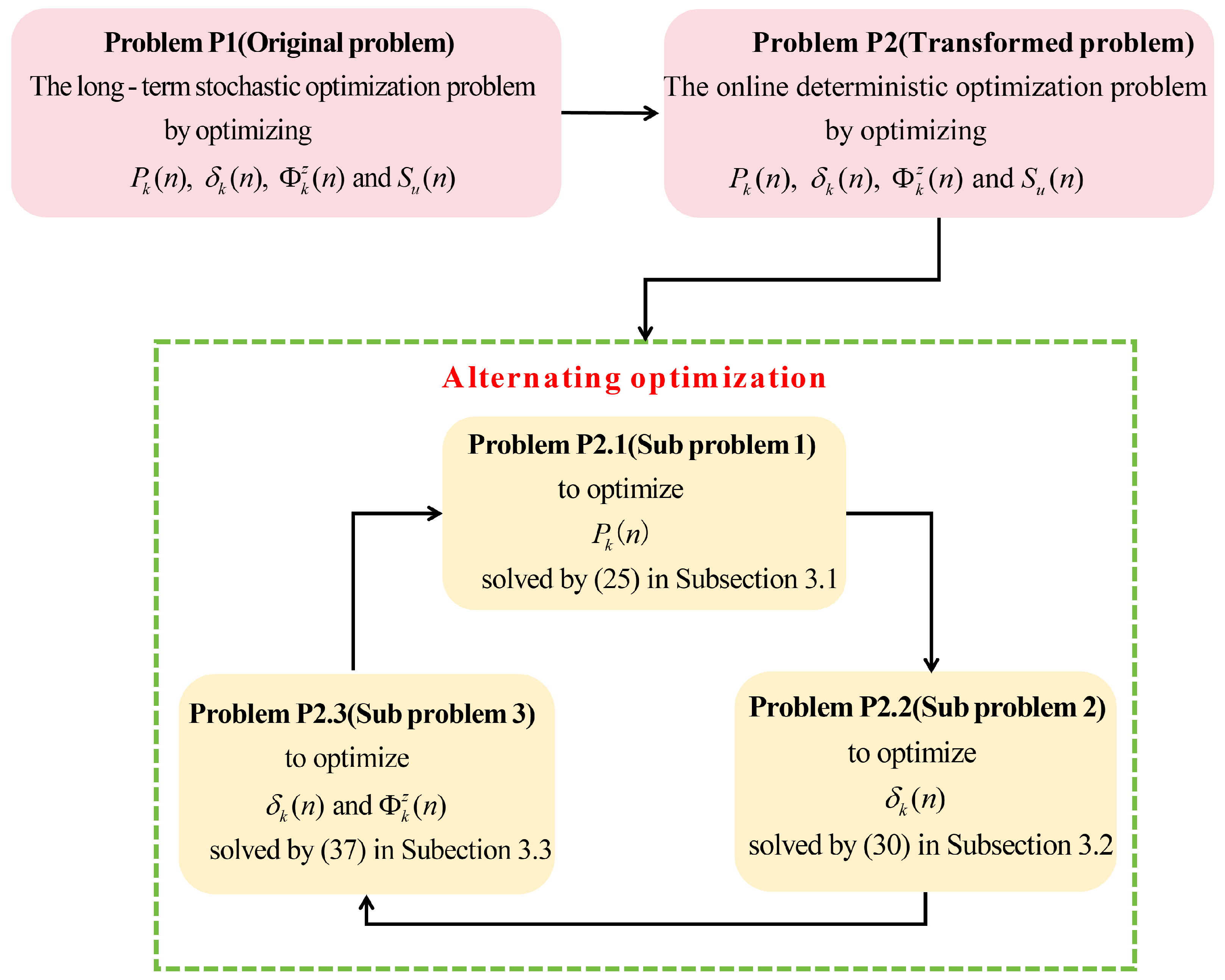
23), the optimization problem can be transformed into
As shown in
Figure 4, after converting
to
, the problem is rephrased as an online optimization problem. In
, there is a serious coupling relationship between optimization variables, which makes it difficult to solve this problem. To solve this problem, we will transform it into three subproblems that can be alternately optimized and solved: (1) optimization of transmission power; (2) time slot allocation; (3) optimization of UAV trajectory and intelligent reflector phase matrix. Then, we can alternately solve the three subproblems until the change in variables is less than
, thus obtaining an approximate solution to the objective function.
3.1. Transmission Power Optimization
When
,
, and
are fixed, the GU power allocation problem is expressed as
where
. If
, it is obvious that
is the solution of
. Therefore, we only consider the case of
. Considering that the function in problem
is a transcendental equation, it is necessary to obtain the optimal transmission power by solving the extremum points of the equation. Therefore, we first calculate the first-order partial derivative of
in the equation, and we have
By converting Equation (
26), we can obtain
According to the transformation, we can solve it using the Lambert function, denoted as
. Note that the
function is the inverse of
. Let us assume
, where
,
after the transformation, and we obtain
Considering the existence of constraints, we can obtain
3.2. Time Slot Allocation
After fixing
,
, and
, the system time slot allocation problem can be expressed as
The above problem
is a convex optimization problem that can be solved using Lagrange duality and the KKT conditions. If
, it is obvious that
is the solution of
. Therefore, we only consider the case of
. The Lagrange dual function of the above problem can be rewritten as
where
and
are Lagrange multipliers, and
. According to the KKT conditions, when obtaining the optimal time slot allocation
, we can obtain
By performing simple algebraic processing on (
32a), the optimal
can be obtained
Substitute (
33) into Equation (
32c) to obtain
We can ultimately obtain two solutions: one is
, and the other is
. We need to maintain
and choose to maximize the objective function, that is,
Substitute (
35) into Equation (
32b) to obtain
Equation (
36) is an equation that is only related to
. We can solve the equation using binary division to obtain the optimal Lagrange multiplier
. Then, we can substitute it into (
35) to obtain the optimal
. Finally, we substitute
and
into (
33) to obtain the optimal
.
3.3. UAV Trajectory Planning and STAR–RIS Phase Optimization
The communication gain between the GU and UAV in this system is related to the modulus and phase of each communication link, so we need to optimize the UAV trajectory and STAR–RIS phase angle matrix simultaneously. Due to the use of the TDMA protocol in this paper, the perfect STAR–RIS phase matrix can be obtained in the communication gain of all GUs regardless of the UAV’s position. Therefore, we assume that the phase matrix of STAR–RIS has reached its optimal value in each time slot and transform the problem into one that is only related to the UAV trajectory. In summary, we can directly optimize the UAV trajectory while fixing
and
, resulting in the following:
To solve problem
, we address both the non-convexity of the objective function and the constraints
,
, and
. First, we eliminate the impact of constraints
and
by adjusting the UAV’s flight mode. The UAV operates in normal flight mode to serve GUs, and in each time slot, the optimal position for the next time slot is determined by solving
. If the solution
satisfies the return-to-destination requirement, the UAV calculates the average flight speed from
to
and compares it with the maximum speed
. The UAV then moves toward the optimal position at the lower of the two speeds. If
does not meet the conditions, the UAV will switch from normal flight mode to return flight mode and fly towards the destination position at maximum flight speed
. Through the above scheme, we can eliminate the influence of constraint
and
. Next, in order to address the non-convexity of the objective function, we use recursive SCA to solve the optimal position
. By approximating
as a convex problem and iteratively solving it alternately, we obtain the approximate solution of the trajectory optimal solution. Specifically, by converting
into a first-order Taylor expansion about
and
substituting it into the objective function, we can obtain
where
is the numerical value of the expansion point for the given i-th iteration. After approximating the problem as a convex problem, we solve for the optimal solution in (
41) by finding the extremum points. We take the first partial derivatives of function
relative to
and
, respectively, to make them equal to 0, and obtain two linear correlation equations
Further merge (
42a) and (
42b) to obtain an independent equation, as shown below:
Equation (
27) is a linear function, where any solution
can be the optimal position for the UAV in the next time slot. According to Equation (
27), we can obtain multiple optimal solutions for the objective function. Considering the time and energy consumed by the UAV’s position changes, we choose the point closest to
as the optimal position
to minimize the UAV’s flight distance. Then, the optimal trajectory
obtained from the solution is used as the expansion point for (
i + 1) iterations. When the change in the final trajectory is less than
, the asymptotic optimal solution can be obtained.
In the above UAV optimal trajectory solving process, we assume that the phase matrix of STAR–RIS is the optimal solution, so we only need to derive the optimal phase matrix based on the final optimal position
. Due to the use of the TDMA protocol, we can perform phase optimization in the time slots allocated to each GU, and we can obtain
Therefore, there is the following inequality:
If and only if
, inequality (
45) obtains an equal sign, so we can ultimately obtain
where
represents the component of
corresponding to element
, and
represents the component of
corresponding to element
. Thus, we obtain the optimal phase angle matrix
for STAR–RIS.
4. Algorithm Analysis
In this section, the system stability and complexity of the algorithm proposed in this paper were studied. In Theorem 1, we derived that there is a trade-off between queue backlog and energy consumption.
Theorem 1. Assuming that the trade-off between system stability and energy consumption is feasible, we can obtain It can be concluded from (
47) and (
48) that there are upper bounds on the average queue length and average energy consumption of the algorithm. Please refer to
Appendix B for proof.
Theorem 1 states that the average energy consumption decreases with the increase in control factor V, and the total length of the queue increases with the increase in control factor V. In addition, when the control factor V is large enough, we can obtain the optimal and . Therefore, there is a trade-off between average energy consumption and queue backlog in this system.
Finally, we analyze the complexity of the proposed algorithm. Firstly, the complexity of the algorithm is determined by the alternating iteration process of the three subproblems and the solving process of the three subproblems. Due to the fact that the optimal transmission power, optimal time slot allocation, and optimal STAR–RIS phase matrix are all closed–form solutions with low complexity in the solving process of each subproblem, we mainly consider the complexity of UAV trajectory optimization. Considering the linear convergence of the algorithm and the nested nature of the two processes, we can conclude that the total complexity of the algorithm is . In contrast, the complexity of solving the problem in this paper using the CVX toolbox is . From this, it can be concluded that the algorithm proposed in this paper is a low-complexity algorithm that is more suitable for practical applications.
5. Result Analysis
We evaluate the proposed algorithm from the perspectives of average queue backlog and average total energy consumption through extensive numerical experiments. We simulated a scene of a UAV, a STAR–RIS, and 10 GUs evenly distributed in a large 3D area of 1000 × 1000 m
2. In addition, the initial and final positions of the UAV are
and
, with an altitude of
m and a
of 15 m/s. The number of STAR–RIS elements is
, and the deployment location is
. Then, set the service duration of the UAV to
time slots, with a time slot length of
s, and the important simulation parameters are listed in
Table 1.
Figure 5 shows the flight trajectories of the proposed scheme and UAV without STAR–RIS assistance under different Lyapunov control factors. As shown in the figure, in the proposed scheme, the larger the penalty coefficient
V, the shorter the UAV’s flight distance. This is because an increase in
V indicates a higher weight of energy consumption, and the system will be more focused on energy consumption. Therefore, UAV reduces its flight distance to achieve energy savings, which corresponds to the theoretical results in (
48). Specifically, when
occurs, the system will pay more attention to queue stability, so UAV will hover near STAR–RIS to obtain better channel gain for GUs and handle more tasks. When
occurs, the system begins to focus on energy consumption, gradually shifting its focus from queue stability to energy consumption, shortening the UAV’s flight distance. As
V continues to increase until
occurs, the system will pay more attention to energy consumption, further shortening the UAV’s flight distance. In addition, in UAV–MEC systems without STAR–RIS assistance, due to the extremely harsh communication environment, the UAV chooses shorter flight distances to reduce energy consumption.
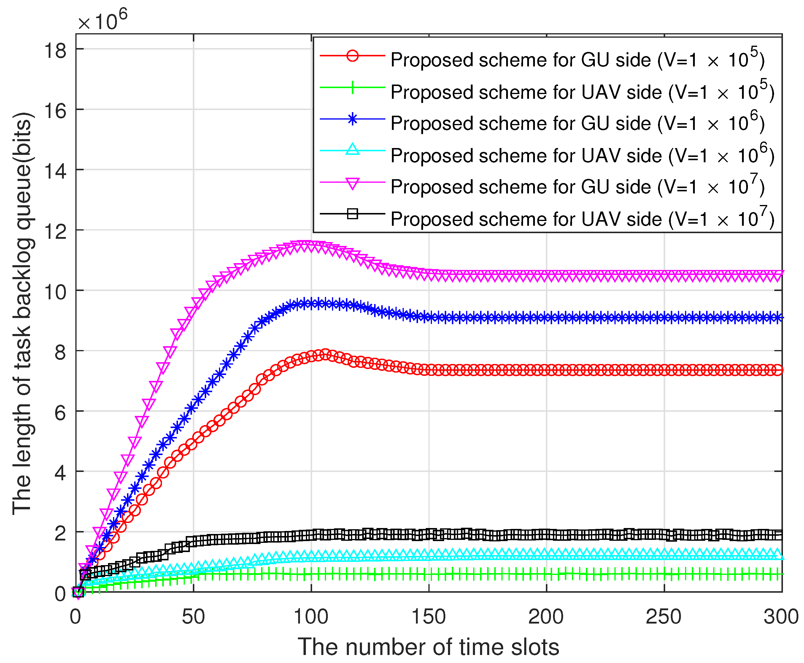
Figure 6 shows the influence of the Lyapunov control factor on system stability. In the figure, it can be seen that the queue length of GUs is much larger than that of UAV, because UAVs have a much faster processing speed than GUs. In addition, as the time slots increase, all GU queues first grow rapidly, then slowly decrease, and eventually stabilize in the region. All UAV queues first grow and then gradually stabilize. This is because when the UAV takes off from its initial position, it is far away from the GU center and STAR–RIS, with a poor channel gain, which makes it difficult to offload tasks in a timely manner, resulting in a backlog of GU queues. As the UAV trajectory is adjusted, the UAV will gradually approach the center and STAR–RIS. At this time, the GU’s channel gain gradually increases, allowing more tasks to be offloaded onto the UAV, resulting in a gradual decrease in the GU’s queue. When the UAV reaches the optimal position, the communication channel gain fluctuates very little, and the number of tasks generated in each time slot is balanced with the number of tasks processed locally and by the MEC server. At this point, both the GU queue and the UAV queue tend to stabilize. Furthermore, as the
V value increases, the length of each queue also increases. The reason is that the increase in
V leads to a higher proportion of energy consumption, and the system tends to lean more towards energy consumption between queue stability and energy consumption, resulting in an increase in queue backlog.
Figure 7 illustrates the variations in system energy consumption under different control factors
V. At the initial stage of UAV task processing, the communication channel gain is relatively low due to the UAV’s distant position from the GUs and the STAR–RIS. This results in higher energy consumption for transmission tasks, as more power is required to maintain reliable communication over a weaker channel. Consequently, the total energy consumption is initially high. As the UAV moves closer to the center area of the GUs and the STAR–RIS over successive time slots, the channel gain improves significantly. This improvement reduces the energy required for transmission tasks, leading to a gradual decrease in total energy consumption. However, when the UAV reaches its final position, the channel gain begins to decrease again due to the increased distance from the GUs or potential obstacles, causing a corresponding rise in energy consumption. Furthermore, the control factor
V plays a critical role in balancing energy consumption and system performance. As
V increases, the system places greater emphasis on minimizing energy consumption, which is achieved by optimizing the UAV’s trajectory and transmission power allocation. This results in a noticeable reduction in system energy consumption, as demonstrated in
Figure 7. This behavior aligns with the theoretical framework established in (
47), which highlights the trade–off between energy efficiency and system performance controlled by
V.
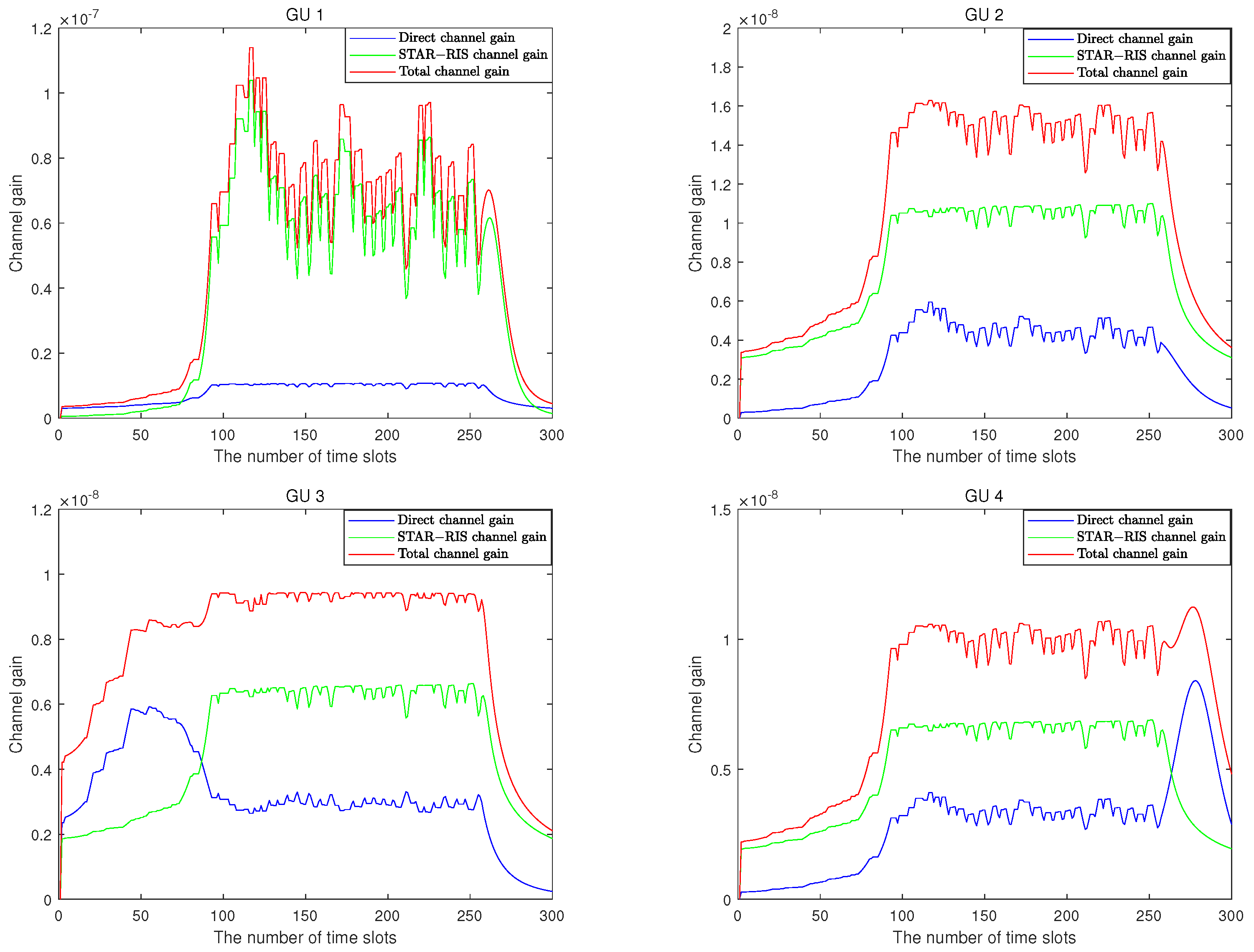
Figure 8 provides the channel gains of four GUs. The total channel gain is the sum of the direct channel gain and STAR–RIS channel gain. As can be seen from the figure, the channel gain brought by the STAR–RIS auxiliary system makes the total gain of each GU much higher than the direct channel gain, greatly improving the communication quality between GUs and the UAV. Furthermore, all three channel gains gradually increase as the drone approaches GUs and STAR–RIS, and due to different positions, GUs enjoy different STAR–RIS gains. GUs closer to STAR–RIS have greater channel gains when communicating with the UAV.
In
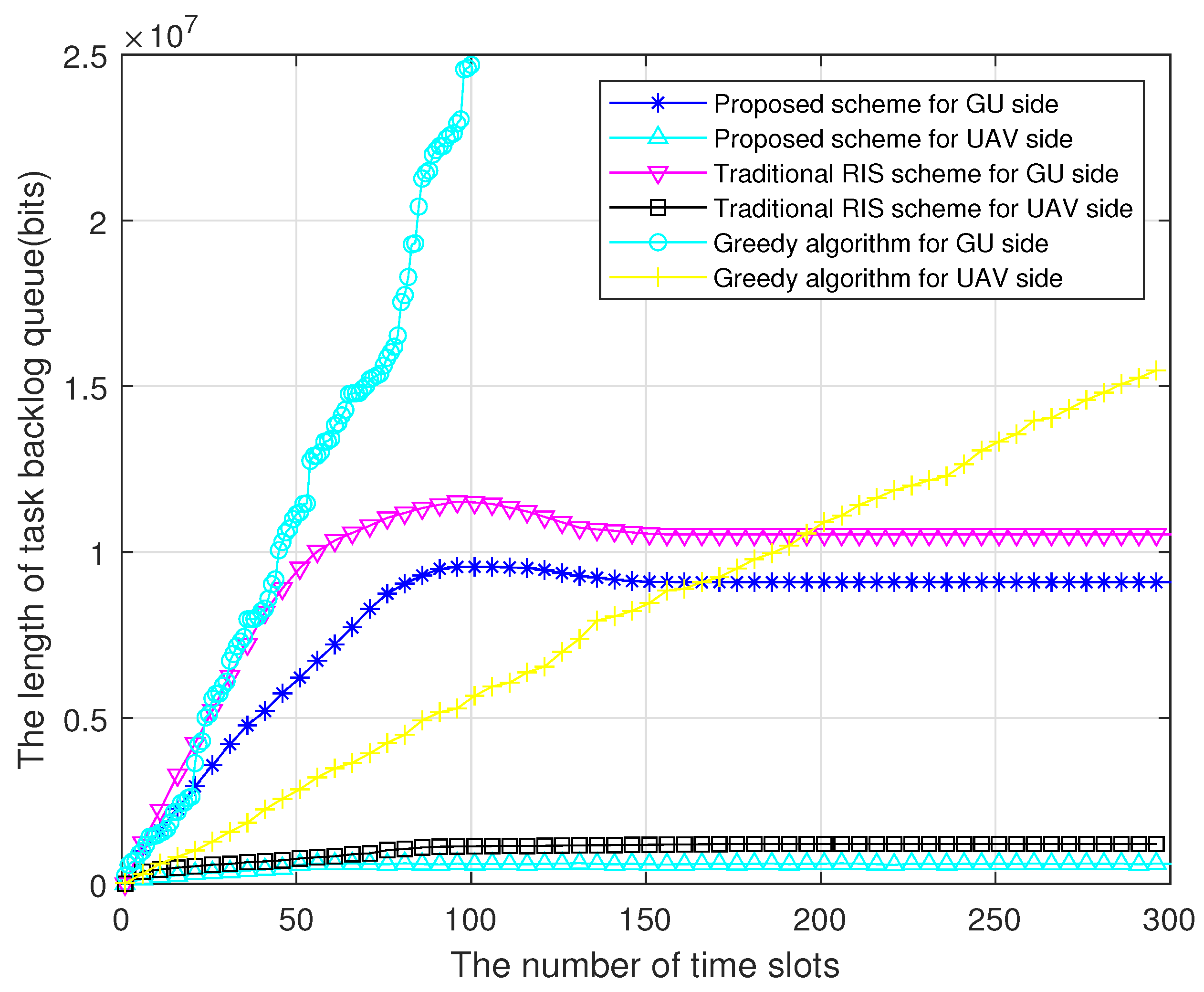
Figure 9, we plot the change curves of the task backlog queue for our proposed scheme and two benchmark schemes. From
Figure 9, it can be seen that if the greedy algorithm is used, the system only focuses on the current optimal resource allocation and does not pay attention to long–term system stability, resulting in more intense competition among GUs and the inability to maintain queue stability. This algorithm that only considers current interests leads to a continuous increase in task queue backlog, resulting in a decrease in system performance and affecting GU experience. In addition, the scheme proposed in reference [
34] uses traditional RIS to optimize the unmanned aerial vehicle–mobile edge computing (UAV–MEC) system. While this method does achieve stable results, the length of the queue backlog remains longer compared to our proposed scheme. The reliance on traditional RIS introduces limitations due to its static positioning, which hinders efficient resource utilization and prolongs the processing delays. Therefore, STAR–RIS is introduced in the model of this paper to avoid the positional defects of traditional RIS. STAR–RIS can be dynamically deployed at the center position of ground users (GUs), providing significant channel gain improvements. This adaptability ensures that the communication links are consistently optimized, thereby enhancing overall system performance. At the same time, a low–complexity and highly efficient resource allocation algorithm is designed to effectively reduce queue backlog. This algorithm takes into account both current and future resource demands, ensuring balanced and stable queue lengths. By intelligently allocating resources and leveraging the enhanced capabilities of STAR–RIS, our proposed scheme outperforms existing methods in maintaining system stability and reducing task backlog.
In order to investigate the impact of more factors on the total energy consumption of the system,
Figure 10 studies the effects of different GU and STAR–RIS unit numbers on the total energy consumption. Both benchmark schemes were set up to compare with the proposed scheme in this paper. In
Figure 10a, as the number of GUs increases from 5 to 25, the total energy consumption increases from 0.15 J to 0.49 J. This is because the increase in GUs leads to intensified competition for communication resources, resulting in higher energy consumption. In
Figure 10b, as the number of STAR–RIS units increases from 100 to 500, the total energy consumption decreases from 0.28 J to 0.15 J. This is because the increase in STAR–RIS units improves the channel gain of the communication link and reduces the energy consumption of GU offloading tasks.
Meanwhile, we can conclude that the total energy consumption of the proposed scheme in this article is lower than that of the other three benchmark schemes. The greedy algorithm only considers the current energy consumption and does not take a holistic perspective, making it unsuitable for solving the long–term optimization problem in this article. Therefore, it has the highest energy consumption. Although CPSO has lower energy consumption than the greedy strategy, as an intelligent optimization algorithm, it is prone to getting stuck in local optima, and due to its high complexity, it is difficult to apply in practical scenarios. However, the algorithm in this article cleverly utilizes the properties of convex functions to transform the problem into three subproblems to be solved alternately and uses mathematical methods to derive closed-form solutions of each subproblem, effectively reducing the complexity of the algorithm and significantly improving the accuracy of the solution. Therefore, the algorithm proposed in this article can achieve lower energy consumption. In terms of modeling, traditional RIS is used to modify the UAV–MEC system in reference [
34]. Although it effectively reduces energy consumption, the STAR–RIS proposed in this article outperforms traditional RIS in modeling and provides more communication resources.
6. Conclusions
This paper investigates STAR–RIS–assisted UAV–MEC networks and proposes a low-complexity resource allocation algorithm based on Lyapunov theory. By replacing traditional RIS with STAR–RIS, we improve communication quality in harsh environments, achieving full-space coverage between UAVs and GUs. The Lyapunov theory transforms the long–term optimization problem into an online optimization problem, and the objective function is solved by iteratively optimizing three subproblems. Simulation results demonstrate that the proposed scheme significantly outperforms benchmark methods (greedy algorithm, CPSO algorithm, and traditional RIS scheme) in terms of queue stability and energy efficiency. Specifically, the proposed scheme achieves a significantly lower user average task queue length compared to the greedy algorithm, CPSO algorithm, and traditional RIS scheme, with reductions of 46.7%, 33.3%, and 20%, respectively. Furthermore, the proposed scheme demonstrates a substantial reduction in average energy consumption, achieving improvements of 68.6%, 56%, and 42.1% over the greedy algorithm, CPSO algorithm, and traditional RIS scheme scheme, respectively. These results highlight the superior performance of our scheme in maintaining queue stability and reducing energy consumption. Future work will explore resource allocation schemes for multi-UAV/RIS scenarios.


