Article

A Novel Telescopic Aerial Manipulator for Installing and Grasping the Insulator Inspection Robot on Power Lines: Design, Control, and Experiment

1
Ji Hua Laboratory, Foshan 528200, China
2
Guangdong Provincial Key Laboratory of Intelligent Decision and Cooperative Control, Guangdong-Hong Kong Joint Laboratory for Intelligent Decision and Cooperative Control, and the School of Automation, Guangdong University of Technology, Guangzhou 510006, China
3
State Grid Beijing Electric Power Company, Beijing 100031, China
*
Author to whom correspondence should be addressed.
Drones 2025, 9(11), 741; https://doi.org/10.3390/drones9110741 (registering DOI)
Submission received: 10 September 2025 / Revised: 20 October 2025 / Accepted: 21 October 2025 / Published: 24 October 2025

Highlights

What are the main findings?
  • A novel lightweight telescopic aerial manipulator with three degrees of freedom is developed, incorporating two scissor-linkage mechanisms and a pitch rotation joint, enabling a large operational range (360–800 mm) while maintaining a total mass of only 2.2 kg.
  • A hybrid position/force control strategy combined with a robust visual detection and estimation algorithm is proposed, allowing the system to autonomously grasp and install a 3.6 kg insulator inspection robot on power lines under real-world outdoor conditions.
What are the implications of the main findings?
  • Various types of performance tests are carried out, and the outdoor operation test is realized for the first time, which effectively promotes the industrial application of aerial manipulators.
  • It provides a practical and safer alternative to manual high-altitude work on power lines, potentially reducing operational risks and costs for the maintenance of electrical infrastructure.

Abstract

Insulators on power lines require regular maintenance by operators in high-altitude hazardous environments, and the emergence of aerial manipulators provides an efficient and safe support for this scenario. In this study, a lightweight telescopic aerial manipulator system is developed, which can realize the installation and retrieval of insulator inspection robots on power lines. The aerial manipulator has three degrees of freedom, including two telescopic scissor mechanisms and one pitch rotation mechanism. Multiple types of cameras and sensors are specifically configured in the structure, and the total mass of the structure is 2.2 kg. Next, the kinematic model, dynamic model, and instantaneous contact force model of the designed aerial manipulator are derived. Then, the hybrid position/force control strategy of the aerial manipulator and the visual detection and estimation algorithm are designed to complete the operation or complete the task. Finally, the lifting external load test, grasp and installation operation test, as well as outdoor flight operation test are carried out. The test results not only quantitatively evaluate the effectiveness of the structural design and control design of the system but also verify that the aerial manipulator can complete the accurate automatic grasp and installation operation of the 3.6 kg target device in outdoor flight.

1. Introduction

High-voltage power lines need to be inspected and maintained regularly, but they usually cover long distances and require skilled workers to climb and work at high altitudes. Manual inspection and maintenance of high-voltage power lines is not only inefficient and dangerous but also a significant economic expenditure [1]. In order to improve the automation of power line inspection, researchers have invested a lot of energy to develop different types of ground-based robotic arms or power line crawling inspection robots [2,3,4]. These devices have avoided manual high-altitude climbing operations to some extent, but there are still many application limitations, which do not meet the rapid deployment standards. In recent years, the aerial manipulator, which is composed of an unmanned aerial vehicle (UAV) and operating manipulator, provides a new means for the inspection and maintenance of power lines [5,6]. On the ground, the operator controls the aerial manipulator to make it fly to the operation position, and the operation manipulator can replace the manual contact operation. The operation of the aerial manipulator has many advantages, such as safety and efficiency, cost saving, flexible control, less space constraints, and ease of integration with the traditional manual maintenance mode, which effectively broadens the maintenance mode of high-voltage power lines.
The aerial manipulator has been applied in the scene of object sampling [7,8], sensor installation [9,10], pipeline detection [11,12], equipment maintenance [4,13,14,15,16], etc. The inspection operation of the aerial manipulator in the power line is not only the technical leap of the traditional manual high-altitude climbing inspection but also the mode innovation of the UAV power inspection technology. More and more researchers have carried out relevant research on the key technologies of an aerial manipulator suitable for power line inspection. For example, Lobermeier et al. [17] designed an aerial manipulator system for installing line markers on power lines. Li et al. [18] studied the problem of removing foreign objects on transmission lines by an aerial manipulator based on visual servo control. Rodriguez et al. [19] designed an installation tool carried by a UAV for the installation of clip-type bird flight diverters on overhead power lines. Perez et al. [20] developed a compliant and lightweight aerial manipulator system, which can be used for a UAV to perform inspection and maintenance tasks near the power line. Suarez et al. designed standard and long-reach aerial manipulator systems for the inspection and maintenance tasks of power lines [21,22,23], and carried out installation research and experiments on clip-type bird diverters and helical bird diverters on power lines [24,25]. From the existing research results, it is found that the aerial manipulator can replace the operation task of workers on the power line by carrying maintenance equipment [26,27]. This not only improves the efficiency of work but also reduces the risk of workers working at height.
As a key component of high-voltage power lines, insulators have been exposed to the sun, rain, and natural aging for a long time. The effective operation of insulators substantially affects the safety of the power system [28,29]. The requirements of the insulator inspection task are very strict. The existing manual inspection methods are usually inefficient and dangerous. In particular, for ultra-high-voltage (UHV) power lines, the traditional manual operation cannot carry out high-altitude inspection on insulators in live operation, which is a difficult problem to be solved in this field at present [30,31]. In the existing technology, the use of the UAV platform for insulator inspection is mainly focused on the use of vision or infrared cameras to detect surface features or damage of insulators [32,33,34,35]. For example, Rahman et al. [36] detected insulator damage based on autonomous vision by using a UAV to obtain real insulator images. Li et al. [37] used the UAV intelligent inspection system to detect and prevent heating of composite insulators in 500 kV power lines. For insulator maintenance tasks, Lopez et al. [38] developed a UAV aerial operation system for insulator surface cleaning and tested it in outdoor environments.
There are few aerial manipulator systems that can be used for insulator inspection, and the existing aerial manipulator technology cannot realize the stable contact inspection of insulator string. That is, it cannot meet the requirements of stable and accurate measurement of the resistance, electric field strength, and surface temperature of each insulator, and it cannot realize the accurate identification of multi-parameter fusion. The crawling inspection robot can be placed on the surface of the insulator string and can achieve stable contact with the insulator. Therefore, it is often used to carry out accurate multi-parameter inspection of insulators in practical applications [39,40,41]. The insulator crawling inspection robot usually has a certain quality, and the installation and retrieval robot are carried by the operator for high-altitude work. It is clear that the operation is physically exhausting, inefficient, and dangerous. Therefore, the approach to install and retrieve the insulator inspection robot on the high-voltage power line has become the thorniest problem in the inspection process. In order to solve that problem, this paper aims at the insulator inspection requirements of the UHV power line, combining the advantages and characteristics of the aerial manipulator and crawling inspection robot. It is the first time researchers have realized the precise installation and retrieval operation of the inspection robot on the power line insulator string by the aerial manipulator.
The main contribution of this paper is the development of a novel telescopic three-degree-of-freedom aerial manipulator system, which can replace workers to install and retrieve the insulator inspection robot at high altitude. The system innovatively adopts two telescopic scissor mechanisms and one pitch rotation mechanism design, taking into account both strength and a lightweight structure. An effective visual detection and estimation algorithm is integrated into the control, and a reliable hybrid position/force control strategy is designed to realize the autonomous grasp and installation of the target device. The developed system is verified by a variety of experiments, and the operation performance of the aerial manipulator is evaluated under outdoor flight.
The paper is structured as follows. The structural design and system architecture of the aerial manipulator are described in Section 2. Subsequently, the kinematic model, dynamic model and instantaneous contact force model of the system are presented in Section 3. In Section 4, the general control framework of the system, manipulator control, and visual detection and estimation are introduced. And in Section 5, the indoor operation and outdoor flight operation tests of the aerial manipulator are carried out. Finally, conclusions are given in Section 6.

2. Aerial Manipulator System

The goal of this work is to develop an aerial manipulator system for automatic and precise installation and retrieval of the insulator inspection robot on UHV power lines. The whole operation process is shown in Figure 1. First of all, the aerial manipulator carries the inspection robot on the ground and flies above the insulator string of the power line. The system relies on depth visual detection and estimation algorithm to determine the hovering position, and to adjust the alignment of the flight platform with the insulator string axis. Secondly, the telescopic manipulator descends and releases the inspection robot, and the inspection robot begins to crawl and inspect the insulator string. Then, after the inspection robot completes the task, the aerial manipulator determines the hovering operation position based on the visual algorithm, and the manipulator descends to complete the grasp and retrieval. Finally, the manipulator retreats to its initial position, and the aerial manipulator carries the inspection robot back to the ground.

2.1. Design Considerations

The telescopic aerial manipulator system will be applied to the inspection of UHV power lines. When working close to the power line, the high-voltage and strong electromagnetic environment are easy to affect the aerial manipulator system [42,43]. Therefore, more design factors need to be taken into account in the design of relevant systems and electromagnetic protection in order to ensure the safe, reliable, and efficient inspection operation of the aerial manipulator.
First of all, the selection of insulation manufacturing materials for the manipulator structure is the key point of this design. It is easy for the aerial manipulator to have close contact with power lines during operation. The potential risk of arc pulling and local breakdown directly determines the strict requirements for the material insulation level [44]. Therefore, it is necessary to select reasonable insulation materials and design the structure of the manipulator so that it can meet the safety requirements of operation in a strong electromagnetic environment.
Secondly, appropriate electromagnetic protection measures need to be taken to ensure the stable operation of the control and communication system of the aerial manipulator. When close to the power line, the strong electromagnetic field interferes with the communication signal of the system, and the damage to the internal circuit system cannot be ignored [45]. The key components of the system must be equipped with shielding or other protective measures to ensure the normal operation of the system. The components to be protected include the surface of aerial manipulator, controller, servo motor, seams of the shell, signal line, power line, etc.
Finally, the aerial manipulator requires low weight and low inertia to minimize the disturbance impact on the multi-rotor flight platform when the manipulator moves, as well as increase the aerial operation time of the aerial manipulator. The design should be balanced and the component layout should be reasonable, so that the impact of structural components on the flight system is minimized. And the structure needs to be made of insulated and lightweight materials. In this work, the mass of the insulator inspection robot is close to 3.6 kg, which means that the aerial manipulator needs to have the capability of lifting at least 3.6 kg. Therefore, both the strength of the manipulator structure and the output torque of the joint servo motor should be taken into account.

2.2. Telescopic Manipulator Design

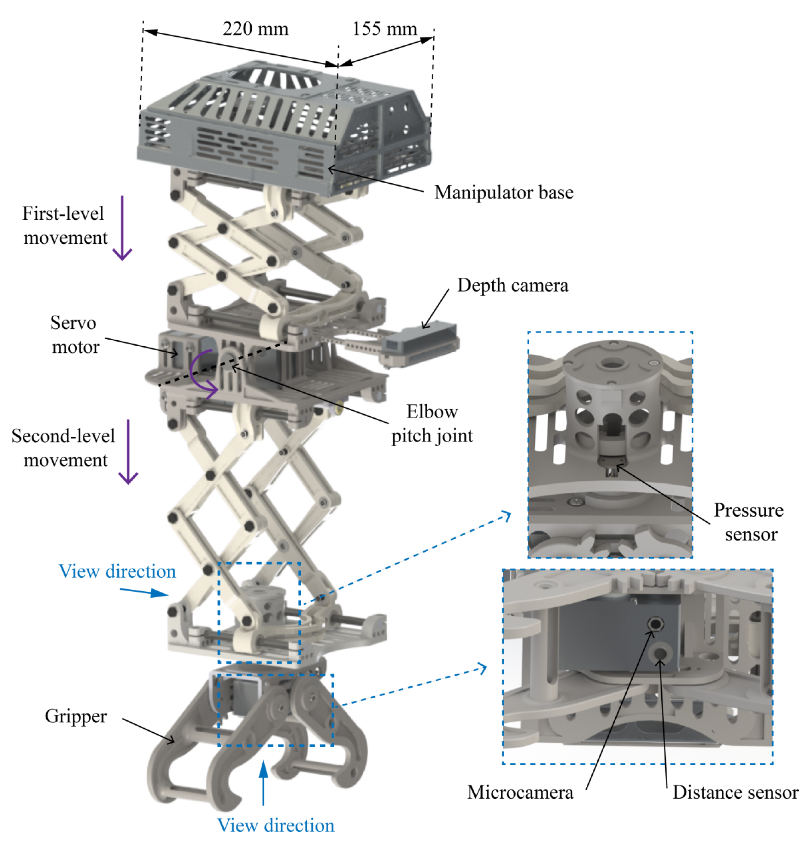
Figure 2 shows the three-dimensional model of the designed telescopic composite manipulator structure. The main parameters of the aerial manipulator are shown in Table 1. The total mass of the telescopic manipulator structure is 2.2 kg. The structure is connected with the bottom of the UAV through the manipulator base by bolts. The power supply of the manipulator is supplied by the UAV battery. The structure contains three degrees of freedom, including two two-stage scissor-linkage mechanisms for up and down motion and an elbow pitch joint for the rotation of the second-layer scissor mechanism. The design principle and structure of the two two-stage scissor-linkage mechanisms are the same, and the length of the connecting bar is 120 mm. Take the first level as an example, where the scissor mechanism is a two-stage scissor-linkage. The servo motor drives the ball screw to rotate, and the support rod connected by the nut makes the scissor bar close or open, thus pushing the platform up and down. In the structure, the screw has very smooth movement, low friction resistance, and no vibration at start-up, so the precise feed control of mechanism lifting can be realized. A RealSense D435i depth camera (Intel Corporation, Santa Clara, CA, USA)with a vertical downward view is arranged at the base of the scissor mechanism on the first layer. The camera is used to detect the outline and central axis of the insulator string. It can assist the operator to align the axis direction of the insulator string when the aerial manipulator is hovering, so as to facilitate the placement of the inspection device.
The gripper of the end-effector of the manipulator is designed with an inner arc shape with gravity self-locking ability. The gripper is meshed with the shape of the inspection robot handle, and the mechanical self-locking can be realized after the grasping device to prevent the object from falling. As shown in Figure 2, the gripper base and the bottom plate of the second-layer mechanism are separated, and a pressure sensor is included between them. The pressure sensor can detect the gravity of the device held by the gripper in real time, which is used for the aerial manipulator to automatically place the inspection robot on the insulator string. The middle of the gripper contains a microcamera and a laser distance sensor. The miniature camera can be used to view real-time images of the gripper operation. The distance sensor can measure the distance between the gripper and the target object in real time, which is used for the aerial manipulator to grasp the inspection robot automatically.
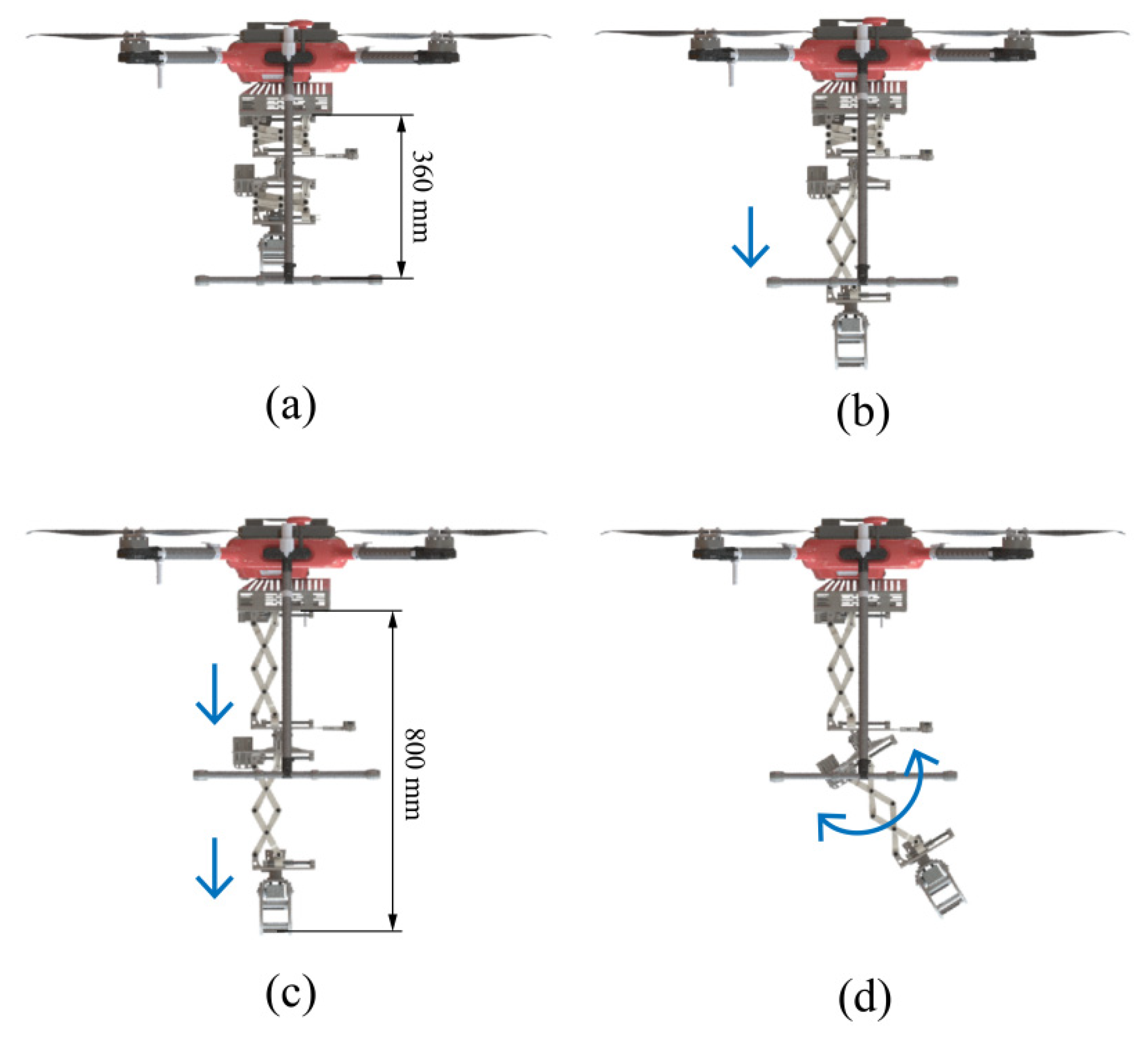
The designed manipulator consists of two telescopic mechanisms and a rotating mechanism. This configuration is specifically chosen to provide the manipulator with a larger and more flexible operational workspace. While a single telescopic mechanism is constrained to linear motion, the integration of a second, independently controlled telescopic arm and a pitch rotation joint enables complex motion within a three-dimensional volume. This design effectively compensates for the limitation of a single-degree-of-freedom telescopic system. Figure 3 shows the operational range of the designed aerial manipulator. During the flight of the aerial manipulator, the manipulator will shrink to the shortest state, with a length of 360 mm, as shown in Figure 3a. This can ensure that when the system is flying with additional objects, the disturbance of external objects on the system stability is as small as possible. Figure 3b shows the lifting state of the aerial manipulator with only the second-layer mechanism. Figure 3c shows that the maximum extension range of the manipulator can reach 800 mm. Furthermore, as shown in Figure 3d, the elbow joint provides a rotation range from −10° to 35°. The combination of these translational and rotational degrees of freedom defines a substantial conical workspace beneath the UAV, allowing the end-effector to access a wide range of positions and orientations. This flexibility is crucial for performing precise tasks such as aligning and installing the inspection robot on the insulator string, as it allows for compensation of positioning errors and adaptation to the target’s geometry.

2.3. Motors and Materials

The aerial manipulator system contains four servo motors, three of which are used for the control of mechanism movement and one for the opening and closing control of the gripper. The servo motors used are Dynamixel (Robotis, Seoul, Republic of Korea) series motors, which are specialized serial bus servo systems for robots and can provide a high torque-to-weight ratio and real-time status information. In the design, the motors are arranged as close as possible to the vertical direction of the mass center of the aerial platform to ensure that the effect of the change in mass center caused by the movement of the manipulator is minimal.
The system is used in high-voltage transmission lines. So that the aerial manipulator system will not be damaged by the strong electromagnetically charged environment when it is close to the high-voltage line, and considering the material insulation, density, strength, and manufacturing difficulty, the manipulator structure in the design is mainly made of glass fiber material and nylon material. The scissor connecting bar and slide rail are the key supporting parts in the structure, and glass fiber is used, which possesses high mechanical strength. The base plate and the gripper parts are made of nylon material with low mass density and good toughness. These structural parts have good strength and can be manufactured using 3D printing, with low manufacturing costs. The manipulator base is made of aluminum alloy 3D printing, which can ensure the reliable strength of the connection between the manipulator and the flight platform.
Four servo motors, a microcamera, a distance sensor, and a RealSense camera are all installed in aluminum–magnesium alloy protective boxes. These are used to isolate the electromagnetic shock caused by the external high-voltage environment and reduce the risk of breakdown of the internal circuit of the component.

2.4. System Architecture

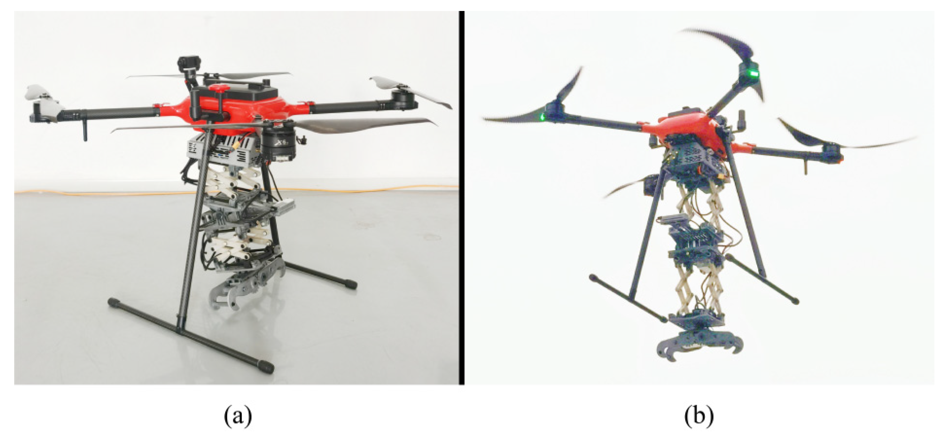
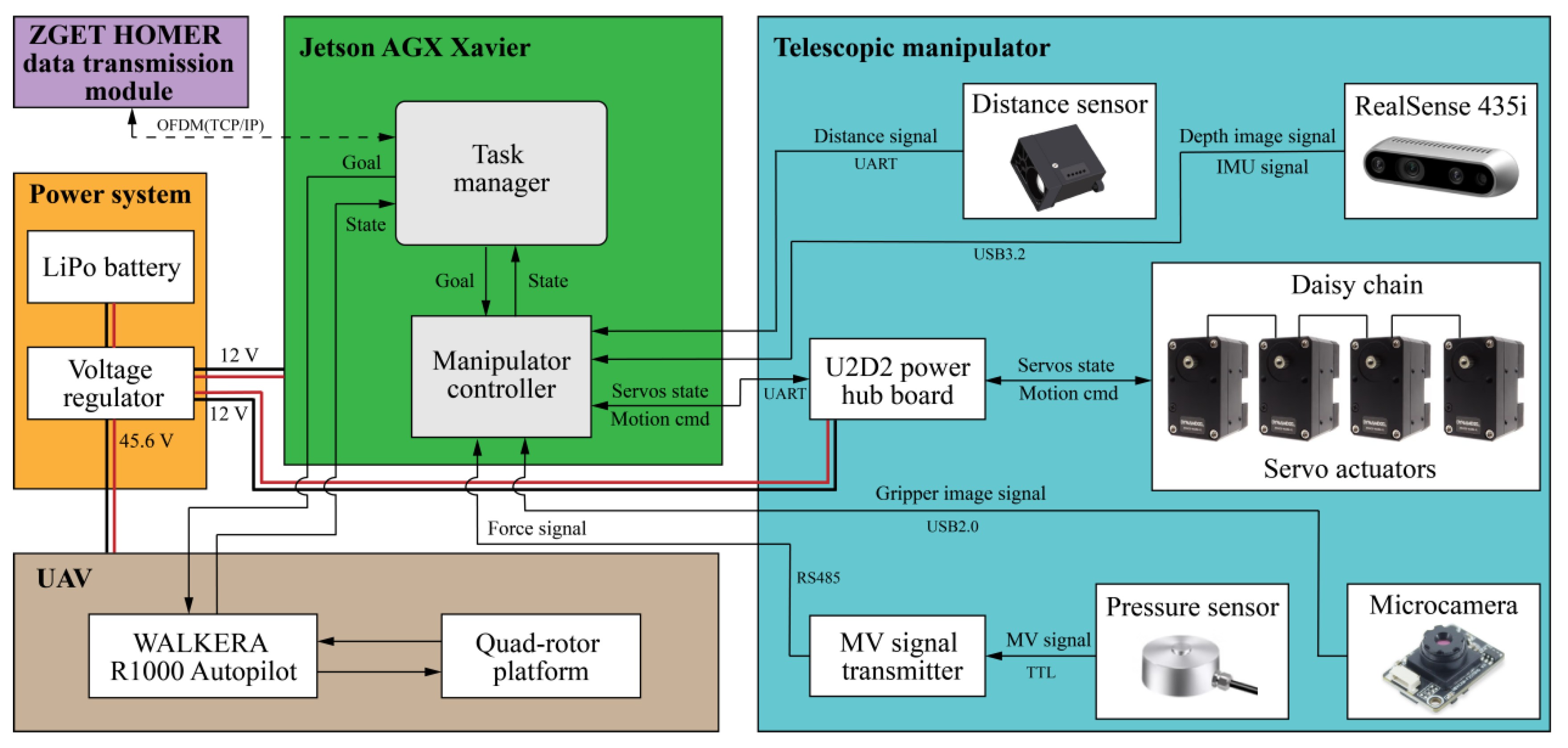
As shown in Figure 4, the designed telescopic manipulator system is integrated into the WALKERA R1000 (Walkera Technology Co., Ltd., Guangzhou, China). The flight platform is a quad-rotor and is equipped with network RTK, which can provide centimeter-level positioning data. The system has a certain anti-electromagnetic interference ability, and the maximum additional load can reach 8 kg. The hardware/software architecture of the aerial manipulator system is shown in Figure 5. The ground control station performs command transmission and control of the aerial manipulator. The system is equipped with a Jetson AGX Xavier (NVIDIA, Santa Clara, CA, USA)computer board, which can effectively complete visual inspection, multi-sensor fusion, artificial intelligence computing, and other tasks, and which has a good development and expansion performance. The data transmission module adopts ZGET HOMER and uses an OFDM wireless communication mode to transmit information, which can realize data transmission over more than 2 km. The entire aerial manipulator system is powered by a 14,000 mAh LiPo 12S battery. The task manager realizes the state monitoring of the UAV system, as well as the monitoring and control of the manipulator system. The UAV consists of a four-rotor platform and a WALKERA R1000 flight control system.
The telescopic manipulator is controlled by the manipulator controller. The system consists of four UART servo actuators in series, and each servo has a unique ID. The control system can access each servo individually, read its state, and control its motion position. The server actuators are DYNAMIXEL series, including two XM430-W350-R and two XM540-W270-R. A RealSense D435i camera is integrated into the system to provide depth image information and IMU data feedback for the aerial operation system. The distance sensor provides distance information feedback to the manipulator controller, which is used for automatic grasping control of the manipulator. After the pressure sensor detects the pressure change, the MV signal is output, and then the signal is fed back to the manipulator controller through the digital transmitter for the automatic placement control of the manipulator. The microcamera provides the image signal of the gripper to assist the operator to judge the working state of the manipulator.

3. Modeling

The aerial manipulator system consists of a four-rotor aircraft with six degrees of freedom and a telescopic manipulator with three degrees of freedom.

3.1. Kinematic Model

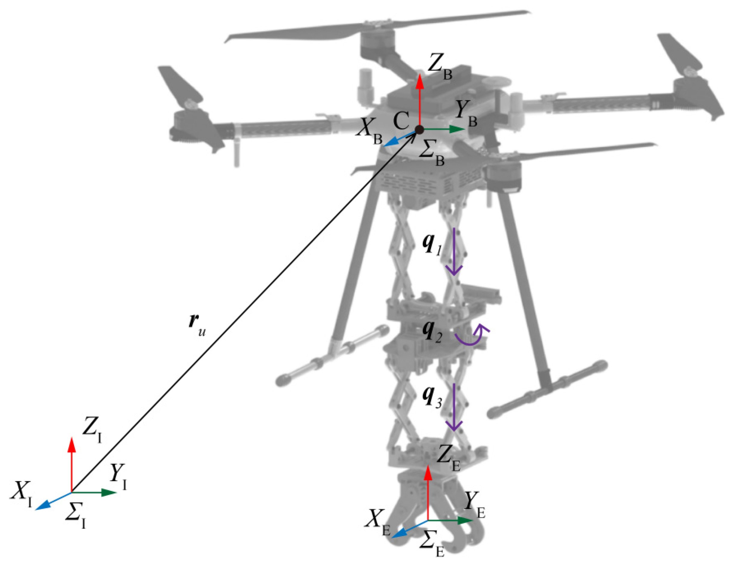
The reference coordinate systems are shown in Figure 6. ΣI is the earth fixed inertial coordinate system. ΣB is the four-rotor body coordinate system, and the coordinate origin C coincides with the centroid of the device. ΣE is the coordinate system of the end-effector of the manipulator. r u is the position of the four-rotor body with respect to the inertial frame ΣI. The position of manipulator joints can be described as vector q = q 1 , q 2 , q 3 T . It should be noted that q1 and q3 are linear motion joints, and q2 is a rotational motion joint.
Let the position of the end-effector in ΣI be p e , and the orientation is expressed by the Euler angle, namely, Φ e = φ , θ , ψ T . It can be expressed as follows:
p e = p b + R b p e b b
Φ e = Φ R b R e b
where p e b b and R e b represent the position and orientation of ΣE with respect to ΣB; p b and R b represent the position and orientation of the multi-rotor with respect to ΣI; and Φ R b R e b represents the Euler angle extracted from the rotation matrix R b R e b .
The velocity and angular velocity of the end-effector in ΣI are expressed as p ˙ e and ω e , respectively. By differentiating Equations (1) and (2), the following can be obtained:
p ˙ e = p ˙ b S R b p e b b ω b + R b p ˙ e b b
ω e = ω b + R b ω e b
where ω b is the angular velocity of the multi-rotor body in ΣB; ω e b is the angular velocity of the end-effector in ΣB; and S is the skew-symmetric matrix operator performing the cross product [46].
The designed aerial manipulator contains two two-stage scissor-linkage mechanisms. Figure 7 shows the kinematic diagram of the designed scissor-linkage mechanism. Let the line of A0B0 be the X axis, where the direction is horizontal to the left, and the line of A0A2 be the Y axis, where the direction is vertical and downward. A0B0 is the initial position of the mechanism, the solid line shows the initial state at this time, and the elongation is h0. The dotted line is the state where the mechanism reaches the target position, and the elongation is hi. From the geometric relation, h0 can be obtained as follows:
h 0 = N l 2 x 0 2
where N represents the number of unit groups of the scissor-linkage mechanism (in this work, N = 2); and l is the length of the link.
In the process of the mechanism of moving from the initial position to the target position at time t, the displacement Δx of B0 can be expressed as follows:
Δ x = x 0 x i = v t = n r p b t
where v is the input speed of B0; nr is the input speed of the servo motor; and pb is the lead of the ball screw.
The scissor-linkage mechanism reaches the target position, and hi can be expressed as
h i = N l 2 x i 2 = N l 2 x 0 n r p b t 2
By differentiating Equation (7), the velocity of Ai can be obtained as follows:
v A i = N n r p b x 0 n r 2 p b 2 t l 2 x 0 n r p b t 2 1 / 2
The acceleration of Ai can be obtained by differentiating Equation (8).

3.2. Dynamic Model

Considering the external interference of the manipulator to the multi-rotor body during grasping, the dynamics of the multi-rotor body are modeled as follows by using the Newton–Euler method [47,48]:
p ˙ b = v b m u v ˙ b = f u R u e 3 m u g e 3 + F d + A Φ ˙ b = T Φ b ω b J ω ˙ b = M u ω b × J ω b + M d + D
where the first two terms represent translational dynamics and the last two represent attitude dynamics; v b represents the velocity of the multi-rotor with respect to ΣI; mu represents the total mass of the multi-rotor body; f u = i = 1 4 f i and M u = M 1 , M 2 , M 3 T represent the total thrust and torque of the multi-rotor; R u represents the rotation matrix from the body coordinate system to the inertial coordinate system; F d = F x , F y , F z T and M d = M φ , M θ , M ψ T represent the force and moment on the base when the system is grasping; Φ b is the orientation of the multi-rotor body; J = d i a g I x , I y , I z is a constant matrix, representing the inertia tensor; e 3 = 0 , 0 , 1 T is a vector; T Φ b represents the transformation matrix between Φ ˙ b and ω b ; and A and D represent the offset of the center of gravity [46].
It is assumed that the Euler angle Φ b ensures the flight safety of the aerial manipulator, and the derivative of T Φ b always exists. Based on Equation (9), the attitude dynamics can be as follows:
M u = J T 1 Φ b Φ ¨ b J T 1 Φ b T ˙ Φ b T 1 Φ b Φ ˙ b + T 1 Φ b Φ ˙ b × J T 1 Φ b Φ ˙ b + M d + D
Combining Equations (9) and (10), define ξ = p b T , Φ b T , q T T , so the general dynamic model of the aerial manipulator system can be expressed as follows:
I ξ ξ ¨ + C ξ , ξ ˙ ξ ˙ + G ξ = u + d + J e f c
Here, I, C, and G are, respectively the inertia matrix, the centrifugal and Coriolis terms, and the gravitational force term. u represents the generalized input of the system. d represents the contact force modeling and dynamic modeling errors during grasping. fc represents the contact force during operation, and J e represents the Jacobian matrix of the force transferred from the end of the manipulator to the joints of the manipulator and the aircraft.

3.3. Instantaneous Contact Force Model

The contact force between the end of the manipulator and the object is the main factor affecting the stability of the system during the dynamic grasping process of the aerial manipulator. Impulse theorem can be applied to dynamic grasping processes [49]. Equation (11) can be expressed in the following integral form:
t 0 t 0 + Δ t I ξ ¨ + C ξ ˙ + G d t = t 0 t 0 + Δ t u + d + J e f c d t
Here, t 0 represents the start time of contact, and Δ t represents the contact time. Similarly, the impulse of the grasped object can be expressed as
t 0 t 0 + Δ t m b λ ¨ b d t = t 0 t 0 + Δ t f c d t
where m b and λ b represent the mass and displacement of the object being grasped, respectively.
Since the contact time is short during dynamic grasping, it can be assumed that only the generalized velocity and generalized acceleration change. Therefore, Equations (12) and (13) can be approximately written as
I ξ ˙ t 0 + Δ t ξ ˙ t 0 = J e p t m b λ ˙ b t 0 + Δ t λ ˙ b t 0 = p t
Here, p t is the impulse in Δ t time. The end-effector of the manipulator has the same speed after contact with the object.
J V ξ ˙ t 0 + Δ t = λ ˙ b t 0 + Δ t
where J V represents the Jacobian matrix of the velocity vector transferred from the aerial manipulator to the end-effector of the manipulator.
By Equations (14) and (15), the impulse p t  can be expressed as
p t = J V 1 m b 1 + I 1 J e 1 ξ ˙ t 0
Therefore, the instantaneous contact force can be expressed as
f c = p t / Δ t = m b J V 1 + m b I 1 J e 1 ξ ¨ t 0

4. Control

When the aerial manipulator automatically grasps or installs the insulator inspection robot, it can be assumed that the aerial platform remains in a hovering state, while the manipulator moves and operates independently. In order to ensure the stability of the aerial manipulator during aerial operations, an adaptive controller is designed in this section.

4.1. Control Framework

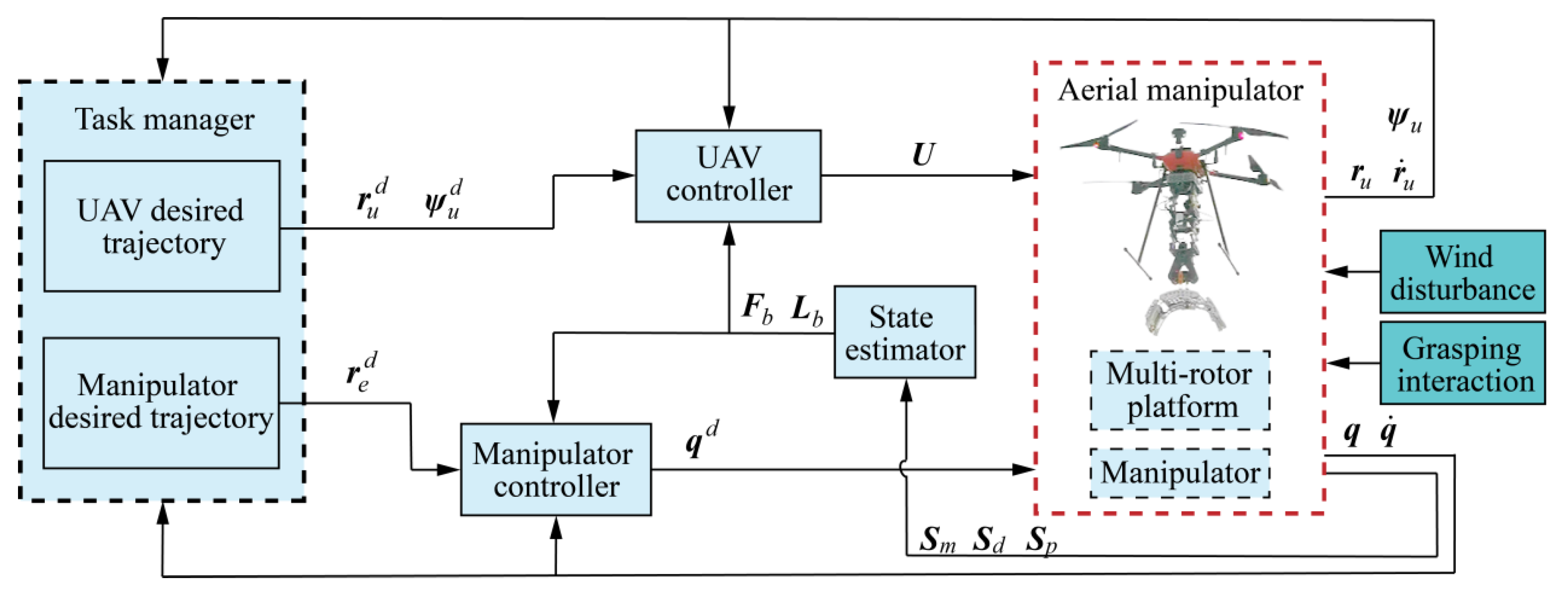
Figure 8 shows the general control framework of the system. The system is composed of a multi-rotor platform and telescopic manipulator. The task manager module generates the desired trajectory r u d and yaw angle ψ u d of the multi-rotor, along with the desired trajectory r e d at the end of the manipulator. In the process of operation, the task manager obtains the multi-rotor r u , r ˙ u , and ψ u state variables in real time through GPS and IMU, and it obtains the q and q ˙ state variables of the manipulator through the joint servos, constantly updates the current state of the system, and completes the specified operation task.
The manipulator controller outputs the desired joint position q d and speed commands required for three joint movements. The performance of grasping and installing the insulator inspection robot is mainly affected by the external wind disturbance and grasping interaction. During operation, the aerial manipulator will detect the data of the system sensors in real time, including image data S m , distance data S d , and force data S p . The state estimator is used to obtain the data of each sensor during the operation of the system, and to evaluate the distance L b between the manipulator and the object in real time, as well as the force change F b in the manipulator grasping the object. These state variables will be fed back to the UAV controller and the manipulator controller. The UAV controller considers the corresponding state information and gives the control signal U of the multi-rotor platform at the output.

4.2. Manipulator Control

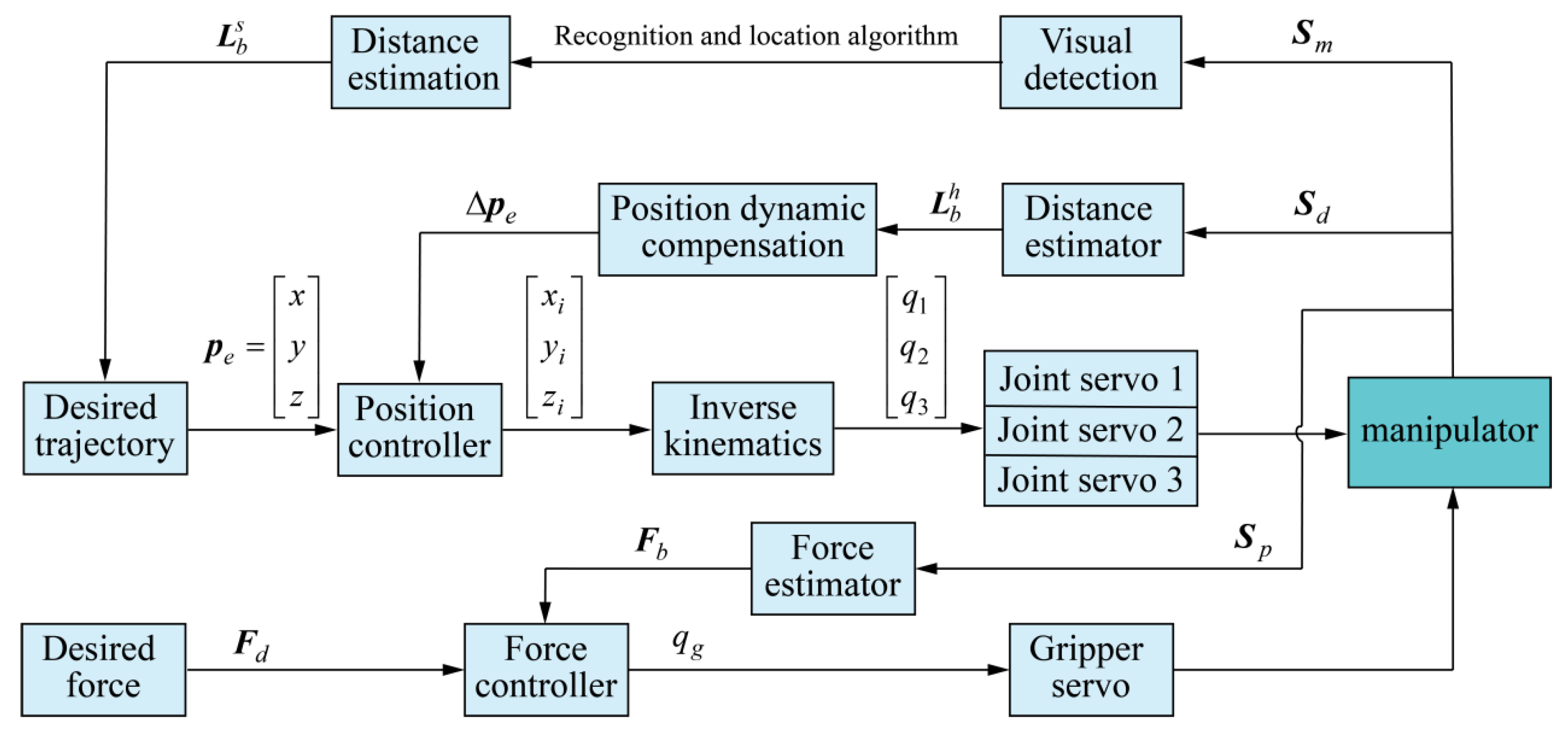
After the aerial manipulator hovers over the insulator string, the telescopic manipulator begins to grasp or install the inspection robot. Figure 9 shows the hybrid position/force control framework designed for the manipulator to automatically grasp/install the inspection robot. The control strategy includes the end position control and force control of the manipulator.
During the grasping operation, the system obtains the insulator string image and point cloud information S m under the manipulator through the depth camera for visual detection. The distance L b s between the insulator string axis and the manipulator is obtained by evaluating the depth value through recognition and location algorithm. The desired position p e at the end of the manipulator is obtained, and a series of path points with a smooth change in velocity profile are generated by the position controller. The desired position values q 1 , q 2 , and q 3 of three joints are obtained through inverse kinematics, and the servos are controlled to reach the manipulator operating position. In the downward movement of the manipulator, the distance sensor inside the gripper will obtain the distance information S d between the gripper and the inspection robot handle in real time, derive L b h through the distance estimator, and dynamically compensate Δ p e  for the position. When the gripper reaches the position of the handle, the manipulator completes the inspection robot grasping, and the inspection robot is lifted.
During the installation operation, the position control method of the manipulator is consistent with the grasping operation. Through the visual detection and the distance estimator, the system obtains the position information between the insulator string axis and the manipulator, then controls the joints through inverse kinematics to achieve the desired operating position. As the inspection robot slowly falls on the insulator string, the insulator string will gradually bear the weight of the inspection robot, and the force exerted by the manipulator on the inspection robot will decrease. The system obtains the force information S p of the manipulator lifting the external object through the pressure sensor, and it obtains the detection value F b in real time through the force estimator. When F b and the desired force F d meet the set conditions, the joint position q g of the gripper is controlled to complete the object release. At this time, the aerial manipulator gripper releases the inspection robot, and the inspection robot can stably fall on the insulator string.

4.3. Visual Detection and Estimation

The aerial manipulator is equipped with RealSense D435i to obtain the point cloud information of the insulator string under the manipulator, and to perform the insulator string detection, distance estimation, and relative position positioning. Point cloud technology has made significant technological breakthroughs and research progress in the past few years. In previous studies, the application of point cloud processing technology in the visual servo of aerial manipulators has been proven to be effective [50,51]. In this work, a depth image instead of an RGB image is used as the input of the target detection network, which has the following two advantages: (1) Adaptable to insulators of different colors: In the course of service, insulators are subject to the effects of sunlight and air, resulting in various colors on their surfaces due to differing degrees of oxidation. (2) Robust to background noise: By delimiting the region of interest (ROI) in the depth image, most of the background noise can be filtered.
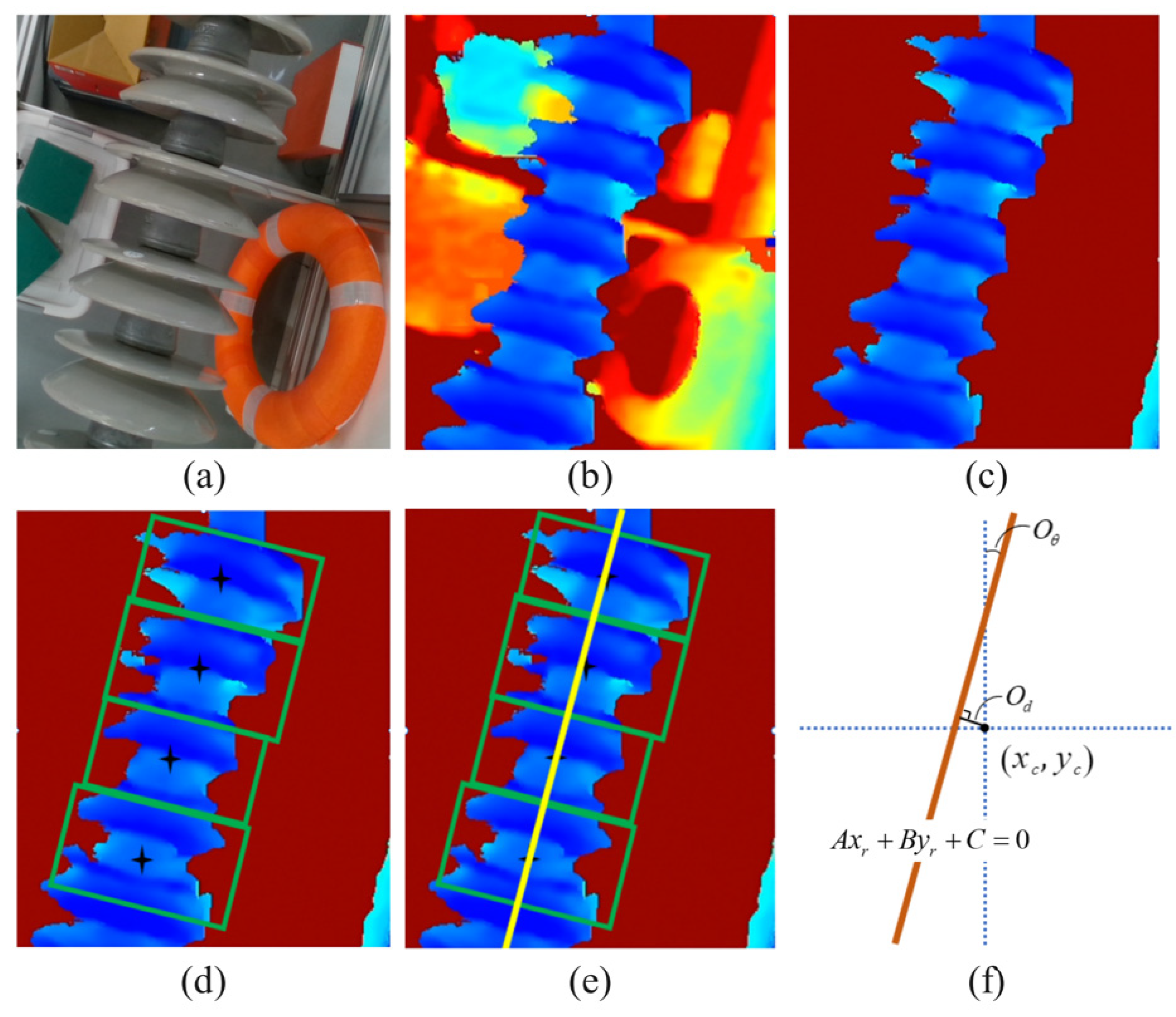
Figure 10 shows the algorithm process of insulator string image detection and estimation under the aerial manipulator. The raw depth image often contains noise and irrelevant environmental data. The preprocessing workflow is designed to enhance data quality and facilitate subsequent detection tasks. Firstly, the RealSense D435i device inputs the original RGB image of the insulator in a complex background, as shown in Figure 10a, and the original depth image, as shown in Figure 10b. Then, we perform image processing to remove noise from the original depth image. A point P i = x i , y i in the depth image. When ROI meets Δ D min , D max , its depth value can be expressed as
d i = d e p t h , d i Δ 0 ,       d i Δ
Image preprocessing for the depth image. For the set d k = d e p t h k = 0 , 1 , j formed by all d i 0 , the probability density function P d of the depth value of the whole image is generated, and its expectation is calculated:
E d = k = 0 j P d = d k d k
Normalize the mapping of depth values in the range of E d D , E d + D to 0 , M . Here, D is the diameter of the insulator, and M represents the upper limit of the grayscale value of the target space. The preprocessing result of the depth image is shown in Figure 10c.
The core visual algorithm involves detecting individual insulators and deriving the central axis of the entire string, as illustrated in Figure 10d. Generally, the object detection algorithm, like YOLO [52,53] or FAST-RCNN [54], can only detect the spatial position ( x , y ) of the object in the image coordinate system, ignoring the information of the rotation angle of insulator. In this work, multi-angle insulator images are used as datasets, where the spatial position and rotation angle O θ of insulators are marked as training data, which enhances the proposed detection algorithm’s precision in meeting the requirements of the aerial manipulator operation scenario.
Then, the central axis of the insulator string is extracted, as shown in Figure 10e. According to the central coordinates of multiple insulators in the image, the Random Sample Consensus algorithm is used to fit the straight line. The parameter average of the N times result A i x r + B i y r + C i = 0 with the smallest distance error is taken as the final axis detection result A x r + B y r + C = 0 . This algorithm demonstrates substantial robustness and maintains precise central axis computation despite the presence of minor errors in detection boxes. As follows,
A = 1 N i = 1 N A i B = 1 N i = 1 N B i C = 1 N i = 1 N C i
Finally, the horizontal offset and rotation offset between the axis of the insulator string and the visual image are calculated, as shown in Figure 10f. The coordinates of the center point in the image coordinate system are set as P c = x c , y c . The horizontal offset and rotation offset of the axis are represented by O d and O θ , respectively, which can be calculated as follows:
O d = A x c + B y c + C A 2 + B 2 O θ = π 2 arctan A B
In this visual algorithm, the distance information between the manipulator and the insulator string is obtained from the depth image, which is used for manipulator motion control. Estimation of the relative position between the aerial manipulator and insulator string is carried out by O d and O θ . When O d and O θ are both close to zero, it means that the aerial manipulator is directly above the insulator string and the gripper is in the same direction as the axis. At this time, the aerial manipulator reaches the optimal operating position when grasping or installing the inspection robot on the insulator string.

5. Experimental Results

This section presents three test results used to validate the performance of the developed aerial manipulator. The experimental environment was designed to simulate the real power line conditions as closely as possible. The insulator strings used in the test are from ultra-high-voltage transmission lines, installed on custom-made support structures, with a height of approximately 1.0 m. This setting can achieve a relatively realistic power operation environment and also enable safe and controllable testing. Firstly, based on the test bench, the changes in angular velocity and torque of joints are analyzed when the manipulator operates external loads. Then, the operation process of manipulator grasping and installing the inspection robot is analyzed, respectively. Finally, the outdoor flight operation test of the aerial manipulator is carried out.

5.1. Lift External Load

The ability to lift an external load can reflect the operation ability of the manipulator on objects of different masses. At the same time, it can also evaluate the motion and torque characteristics of the designed manipulator [55]. In the initial state, the manipulator holds an external load with a mass of 2 kg, and then it carries the load downward and upward. The movement of the manipulator keeps the vertical direction, and the two scissor mechanisms move synchronously.
As shown in Figure 11, the angular velocity and torque changes in the three joints of the manipulator during the external load lifting operation are shown. In Figure 11a, the manipulator starts to move down at 2 s, and the time lasts for 12 s, then moves up, and the whole process takes 32 s. The manipulator controller generates the rotation angle of the joint actuator in a uniform speed process, and joint 1 and joint 3 move synchronously during the motion. Since joint 2 does not move during this process, the angular velocity is 0. In Figure 11b, there are some joint torque spikes due to torque abrupt changes at the start time and stop time of the manipulator.
In Figure 12, the torque of each joint of the manipulator is tested in the lifting of different mass loads. The manipulator motion process is consistent with Figure 11a. In this figure, 0 kg indicates that the gripper has no external load, and the entire lifting load is the weight of the manipulator itself. From the test results, it can be seen that as the external load mass increases, the torque of joint 1 and joint 3 corresponding to each of the two scissors mechanisms gradually increases. When the load is 4 kg, the manipulator still has a certain operational performance.

5.2. Grasp and Install Operation Ability

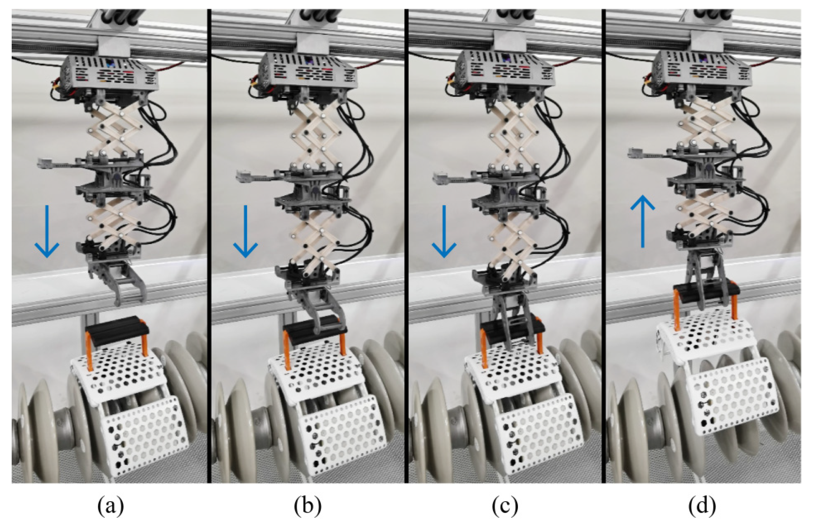
The aerial manipulator is used for grasping and installing the insulator inspection robot on the power line. In order to evaluate the corresponding operational performance, a variety of tests are carried out indoors. Figure 13 shows the different instantaneous images of the inspection robot automatically grabbed by the aerial manipulator on the insulator string. The mass of the inspection robot in the test is 3.6 kg. The manipulator is tested at different distances and heights. The system detects the position information between the gripper and the robot in real time according to the control framework shown in Figure 9, and it completes the automatic grasping operation.
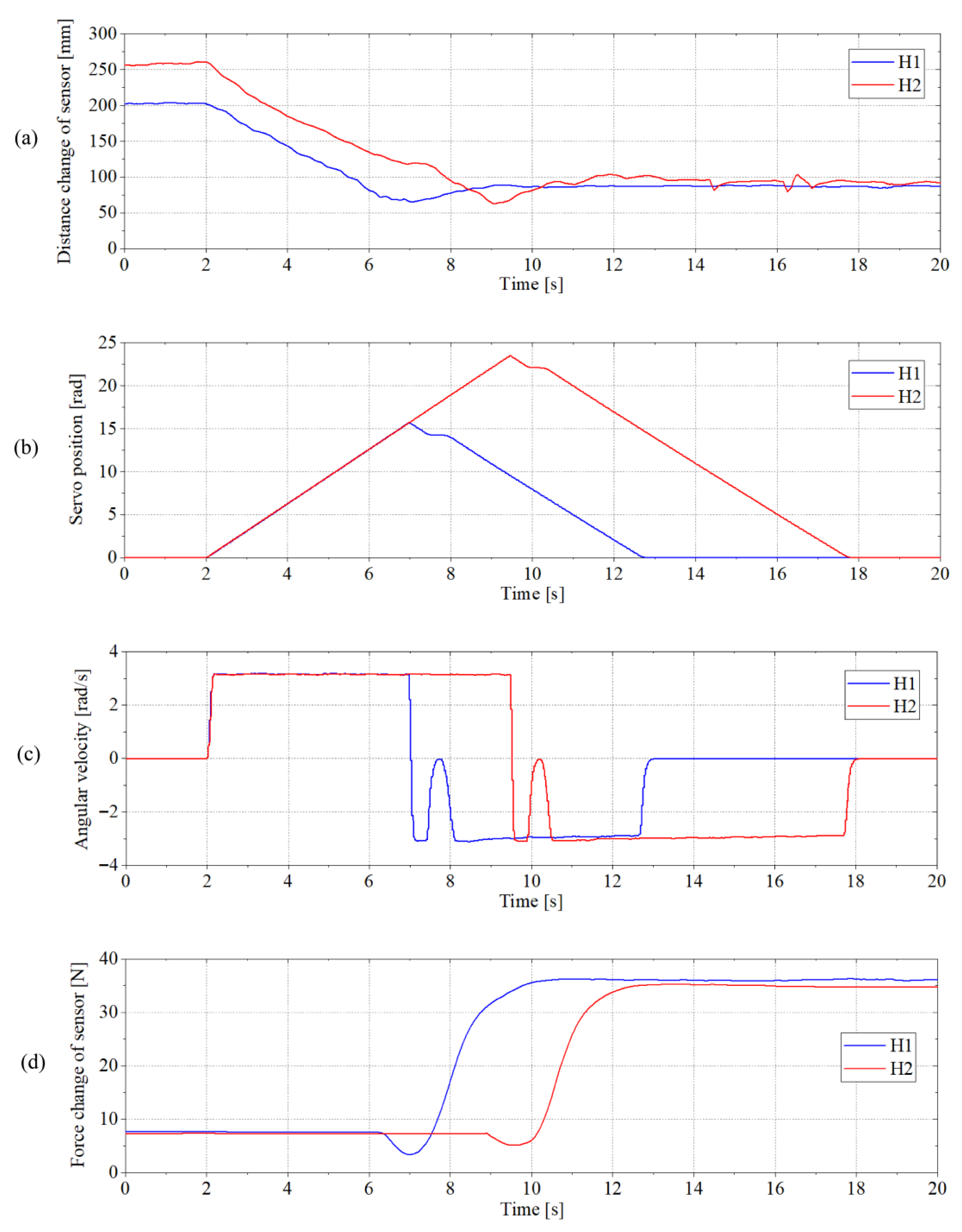
Figure 14 shows the state changes in the manipulator joint servo and system sensors during the grasping operation. The manipulator grasps at two different height positions. The distances between the manipulator and the inspection robot handle are H1 200 mm and H2 250 mm, respectively. As can be seen from Figure 14a, the manipulator starts to move from 2 s. As the manipulator extends downward, the distance from the sensor detection gradually decreases. When the distance between the gripper and the handle reaches 70 mm, the manipulator stops moving downward, and the gripper begins to close, completing the inspection robot grasp. Then, the manipulator is lifted upward, and the distance between the gripper and the handle is stabilized at 90 mm.
Figure 14b,c show the servo position and angular velocity changes in joint 1 during this operation. In the process of grasping, due to the change in the motion direction of the joint motor at the moment of grasping, the angular velocity fluctuates, and then tends to be stable in operation. Figure 14d shows the force change in the pressure sensor at the end of the manipulator during this operation. The pressure sensor is used to measure the force between the gripper and the bottom plate of the second-layer mechanism. Due to the impact of the gripper on the inspection robot during grasping, the force changes. In the lifting process after grasping the inspection robot, the force increases gradually, and the subsequent force tends to be stable.
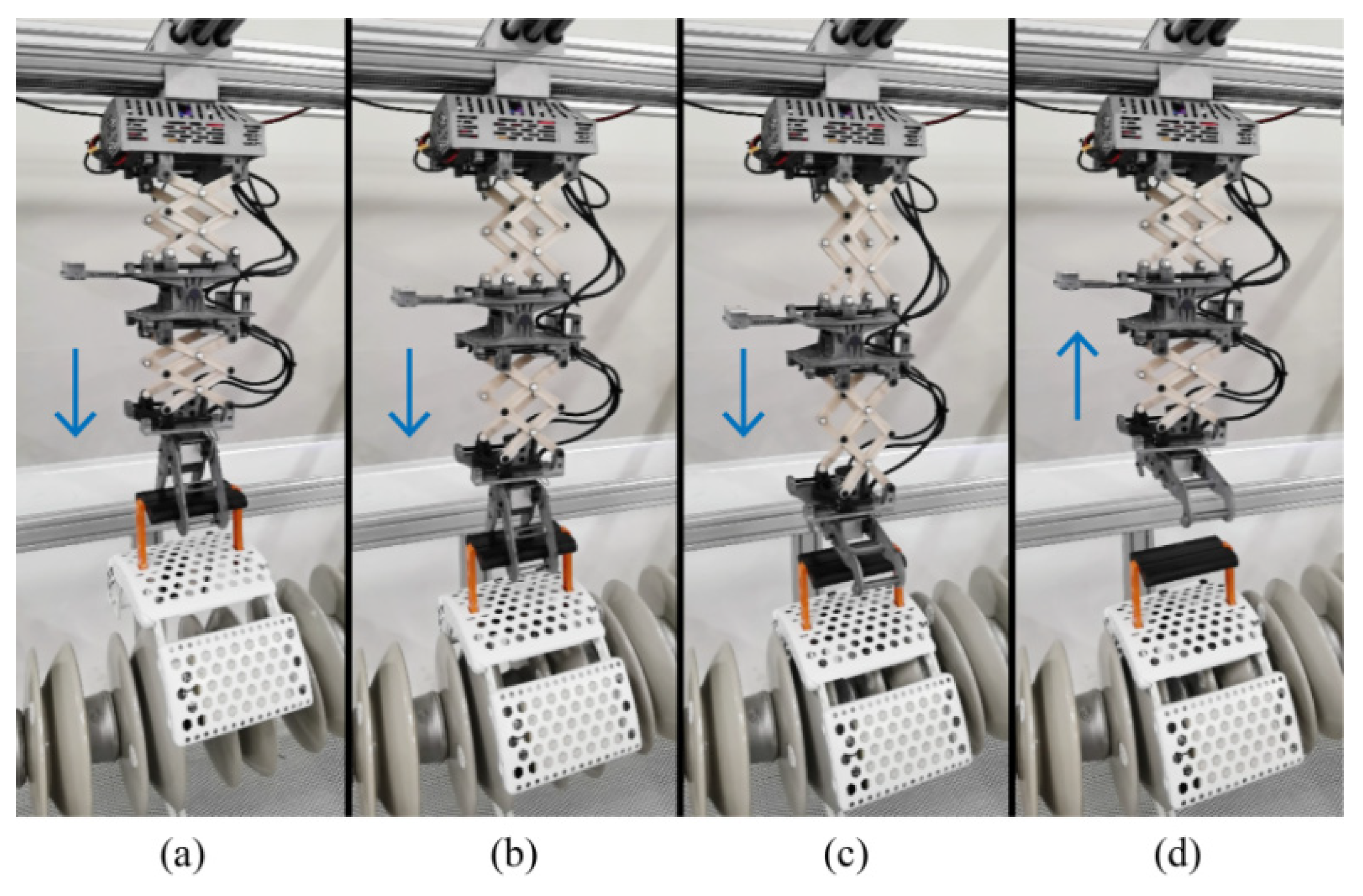
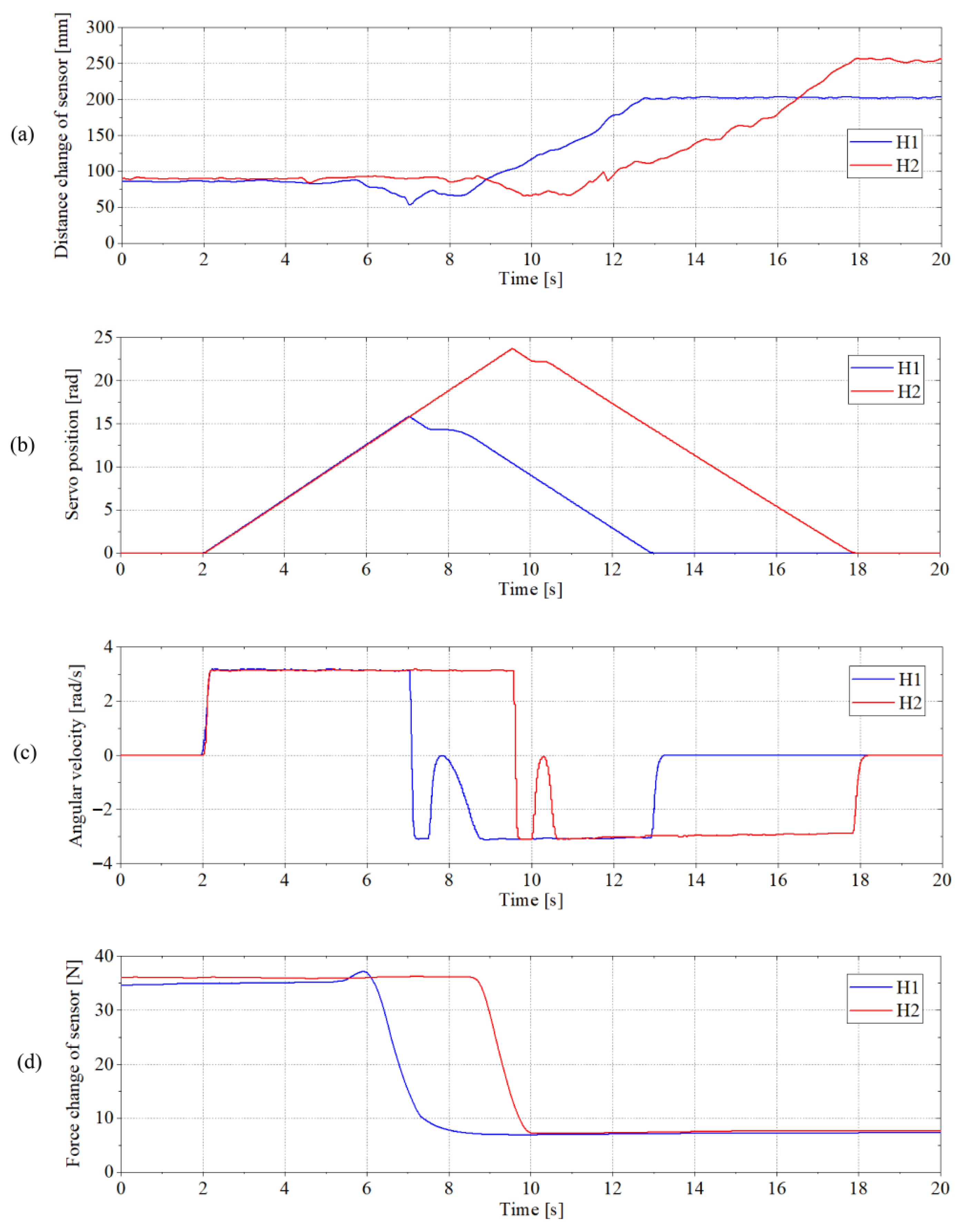
Figure 15 shows different instantaneous images of the aerial manipulator automatically installing the inspection robot on the insulator string. Figure 16 shows the state changes in the manipulator joint servo and system sensors during the installation operation. The manipulator operates at two different height positions. When the height is H1, in Figure 16a, as the manipulator carries the inspection robot downward, it reaches the lowest position at 7 s. At this point, the manipulator stops moving downward, and the gripper opens and releases the inspection robot. Then, the movement direction of the manipulator changes, and the manipulator shrinks upward. Figure 16b,c show the servo position and angular velocity changes in joint 1 during this operation. It is worth noting that in Figure 16d, the value of the force sensor begins to change when it is close to 6 s, because the inspection robot has come into contact with the insulator string. At the beginning of the 8 s, the inspection robot has been completely installed on the insulator string, the manipulator is no longer bearing the weight of the robot, and the force value is close to the minimum.

5.3. Outdoor Flight Operation Test

The unstable interaction force during outdoor flight contact operation and the influence of complex airflow in an outdoor environment make it challenging for the aerial manipulator to grasp and install the target object [9,56]. This section analyzes the operating characteristics of the aerial manipulator through the outdoor flight operation test. Figure 17 shows the operation process images of the aerial manipulator grasping the inspection robot on the insulator string. In the process of operation, the aerial manipulator first flies above the target position and adjusts the yaw angle of the flight platform to adapt to the target object. After hovering and stabilizing, the manipulator extends downwards to grasp the target object. After the grasp is completed, the manipulator shrinks to the initial position and flies away from the operating position with the target.
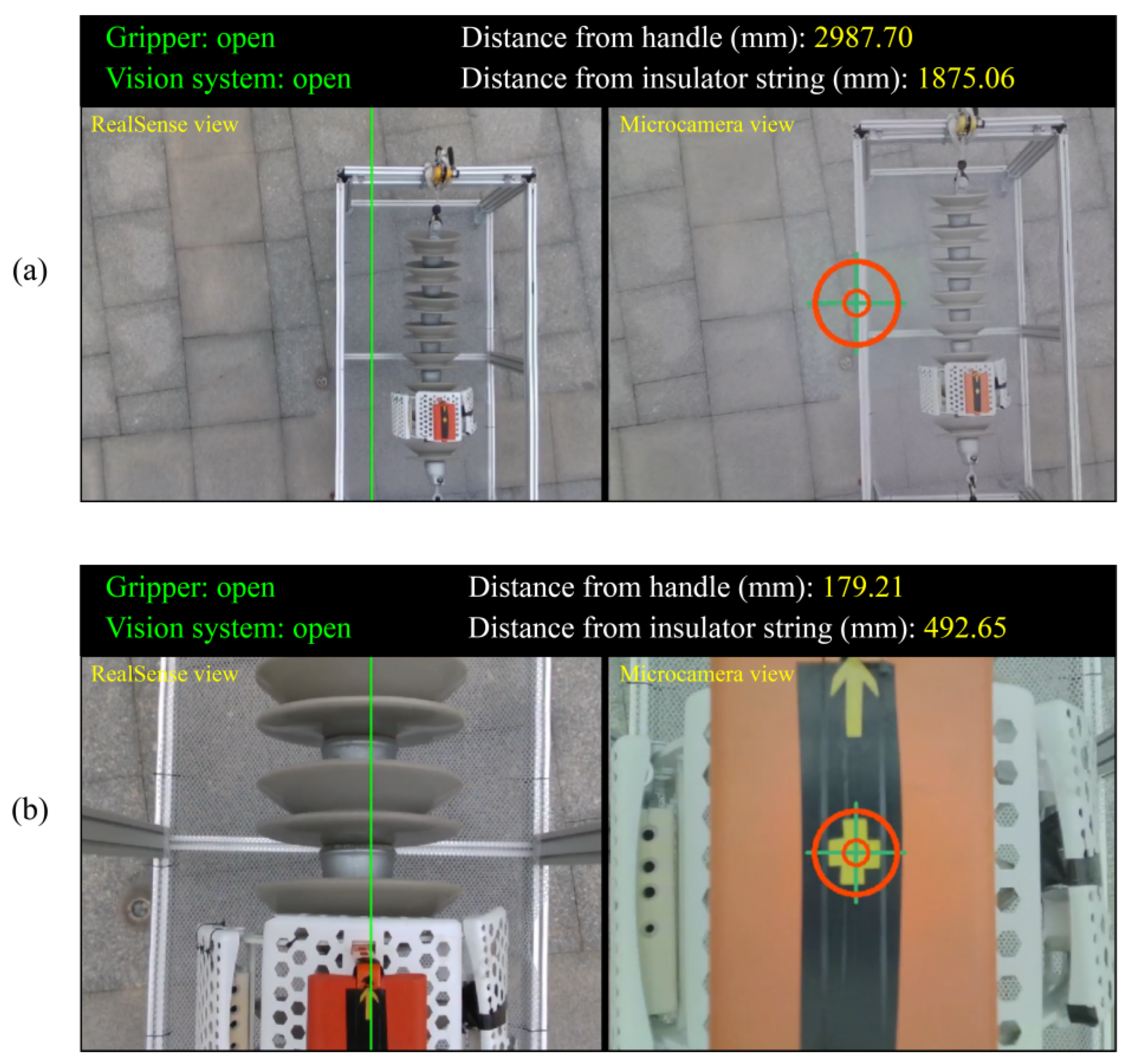
Figure 18 shows the visual image of the system during the operation process in Figure 17, with the RealSense view on the left and the microcamera view on the right. Based on the visual algorithm, the RealSense view is used to estimate the distance information between the aerial manipulator and the insulator string, as described in Section 4.3. Figure 18a shows that the inspection robot appears in the aerial manipulator view. At this time, both the insulator string and the inspection robot have a certain distance from the manipulator, and the aerial manipulator needs to continue to move closer to the target. This state is similar to the scene shown in Figure 17b. As the aerial manipulator continues to approach the target and adjust the system attitude, Figure 18b shows the situation where the target meets the automatic grasping operation. On the one hand, the yaw angle of the aerial manipulator is aligned with the central axis of the insulator string, and the position of the gripper adapts to the target handle. Furthermore, the distance between the aerial manipulator and the target handle satisfies the manipulator extension range. This state is similar to the scene shown in Figure 17c.
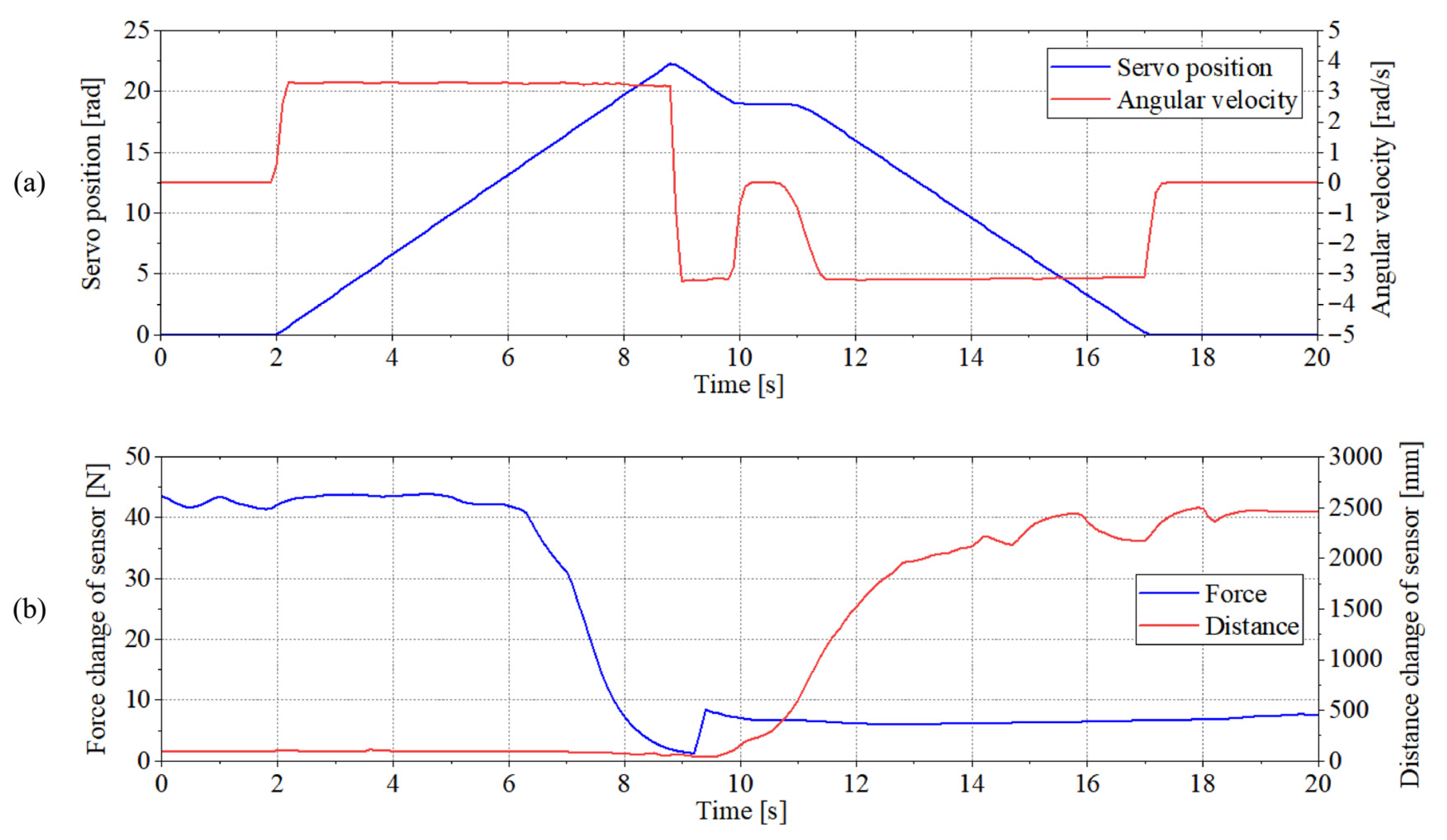
Figure 19 and Figure 20 show the process of outdoor grasping and installing the inspection robot, respectively. These curves record the changes in joint servo motion and the data changes in system sensors during the operation of the aerial manipulator. As shown in Figure 19a, the aerial manipulator stops its downward movement at 5 s and begins to grasp the inspection robot. As can be seen from the force curve in Figure 19b, the inspection robot carried by the manipulator begins to lift from 6 s, and the aerial manipulator gradually bears the weight of the inspection robot.
As shown in Figure 20a, the aerial manipulator stops its downward movement near 9 s, at which time the gripper begins to release the inspection robot, and then the aerial manipulator flies away from the operating position. From Figure 20b, it can be seen that near 9s, due to the instantaneous release of the inspection robot by the gripper, the contact force undergoes a sudden change. Subsequently, after the manipulator completes the release operation, the force value tends to be stable. It can be observed that during the outdoor contact operation of the aerial manipulator on the target object, the interaction force exerted on the system by the target object is constantly changing. There is no significant peak mutation in the overall operation process, and the change is relatively gentle.
Figure 21 shows the linear acceleration change process of the aerial manipulator flight platform in three directions during the operation of the outdoor installation inspection robot. These data are obtained by the IMU of the flight control system. It can be found that the linear acceleration in three directions has a sudden acceleration state when the inspection robot is released, and the flight platform shakes slightly at this time. The acceleration change in the Z direction is the largest, with a maximum value of 3.5 m/s2. This is because the aerial manipulator initially bears the gravity of the inspection robot, and the force’s sudden change occurs in the vertical direction after the object is released.
It can be seen from the data results that during the outdoor operation of the aerial manipulator on the object with a mass of 3.6 kg, the system did not have large acceleration mutation and s significant impact phenomenon. This demonstrates that the designed aerial manipulator system has the ability to complete the corresponding outdoor operation tasks.

6. Conclusions

In this study, we focus on the design, control, and experimental verification of a novel lightweight telescopic aerial manipulator system. This aerial manipulator is used to complete the task of installing and retrieving an insulator inspection robot on a power line, and it can replace workers in high-altitude operations.
(1)
The aerial manipulator has three degrees of freedom, including two telescopic scissor mechanisms and one pitch rotation mechanism, and the total mass of the structure is 2.2 kg. The extensible operation range of the manipulator is from 360 mm to 800 mm under the specifically configured arrangement of various types of cameras and sensors in the structure. The kinematic and dynamic models and the instantaneous contact force model are derived based on the designed aerial manipulator, and the hybrid position/force control strategy, as well as the visual detection and estimation algorithm, are designed.
(2)
Through various types of tests, the load lifting performance of the designed aerial manipulator and the operation performance for grasping and installation of the target device are quantitatively analyzed. In the real outdoor flight operation of the aerial manipulator on the 3.6 kg target, the system can accurately complete the automatic grasp and installation of the target, and the flight platform has no significant impact phenomenon during the operation. It shows that the designed aerial manipulator has the ability to complete the corresponding operation tasks outdoors.
In addition to the operation on the power line, the aerial manipulator is also suitable for fan towers, chemical plants, and other equipment inspection and maintenance. Although the experimental results prove the effectiveness of the proposed aerial manipulator design, the problem of instantaneous system stability of grasping or releasing during operation is not completely solved in this work. As future work, we will further study the disturbance control caused by the motion of the manipulator or the instantaneous release of an external load.

Author Contributions

Conceptualization, P.Y., X.H. and Z.Y.; Methodology, P.Y., H.W., X.H., J.G. and T.D.; Software, H.W.; Validation, P.Y., H.W., J.G. and T.D.; Resources, H.W.; Data curation, H.W. and Z.Y.; Writing—original draft, P.Y.; Writing—review & editing, P.Y.; Supervision, P.Y.; Funding acquisition, P.Y. All authors have read and agreed to the published version of the manuscript.

Funding

This work is supported by the Opening Project of the Key Laboratory of Safety of Intelligent Robots for State Market Regulation (No. GQI-KFKT202302) and the National Natural Science Foundation of China (No. 62573135).

Data Availability Statement

The original contributions presented in this study are included in the article. Further inquiries can be directed to the corresponding author.

Conflicts of Interest

Author Zonghui Yuan was employed by the company State Grid Beijing Electric Power Company. The remaining authors declare that the research was conducted in the absence of any commercial or financial relationships that could be construed as a potential conflict of interest.

References

  1. Ahmed, F.; Mohanta, J.C.; Keshari, A. Power transmission line inspections: Methods, challenges, current status and usage of unmanned Aerial systems. J. Intell. Robot. Syst. 2024, 110, 54. [Google Scholar] [CrossRef]
  2. Seki, H.; Nakayama, S.; Uenishi, K.; Tsuji, T.; Hikizu, M.; Makino, Y.; Kanda, Y. Development of assistive robotic arm for power line maintenance. Precis. Eng. 2021, 67, 69–76. [Google Scholar] [CrossRef]
  3. Li, X.; Shang, D.; Li, F.; Chen, R. The climbing performance analysis of a robot for power line inspection with retractable double serial manipulators. Proc. Inst. Mech. Eng. Part C J. Mech. Eng. Sci. 2022, 236, 4946–4961. [Google Scholar] [CrossRef]
  4. Ollero, A.; Suarez, A.; Marredo, J.M.; Cioffi, G.; Penicka, R.; Vasiljevic, G.; Viguria, A. Application of intelligent aerial robots to the inspection and maintenance of electrical power lines. In Robotics and Automation Solutions for Inspection and Maintenance in Critical Infrastructures; Now Publishers: Delft, The Netherlands, 2024; pp. 178–201. [Google Scholar]
  5. Cacace, J.; Orozco-Soto, S.M.; Suarez, A.; Caballero, A.; Orsag, M.; Bogdan, S.; Ollero, A. Safe Local Aerial Manipulation for the Installation of Devices on Power Lines: AERIAL-CORE First Year Results and Designs. Appl. Sci. 2021, 11, 6220. [Google Scholar] [CrossRef]
  6. Stuhne, D.; Hoang, V.D.; Vasiljevic, G.; Bogdan, S.; Kovacic, Z.; Ollero, A.; Ebeid, E.S.M. Design of a Wireless Drone Recharging Station and a Special Robot End Effector for Installation on a Power Line. IEEE Access 2022, 10, 88719–88737. [Google Scholar] [CrossRef]
  7. Kutia, J.R.; Stol, K.A.; Xu, W. Aerial manipulator interactions with trees for canopy sampling. IEEE/ASME Trans. Mechatron. 2018, 23, 1740–1749. [Google Scholar] [CrossRef]
  8. Samadikhoshkho, Z.; Lipsett, M.G. Visual Servoing for Aerial Vegetation Sampling Systems. Drones 2024, 8, 605. [Google Scholar] [CrossRef]
  9. Hamaza, S.; Georgilas, I.; Fernandez, M.; Sanchez, P.; Richardson, T.; Heredia, G.; Ollero, A. Sensor installation and retrieval operations using an unmanned aerial manipulator. IEEE Robot. Autom. Lett. 2019, 4, 2793–2800. [Google Scholar] [CrossRef]
  10. Ivanovic, A.; Markovic, L.; Car, M.; Duvnjak, I.; Orsag, M. Towards Autonomous Bridge Inspection: Sensor Mounting Using Aerial Manipulators. Appl. Sci. 2021, 11, 8279. [Google Scholar] [CrossRef]
  11. Suarez, A.; Caballero, A.; Garofano, A.; Sanchez-Cuevas, P.J.; Heredia, G.; Ollero, A. Aerial manipulator with rolling base for inspection of pipe arrays. IEEE Access 2020, 8, 162516–162532. [Google Scholar] [CrossRef]
  12. Meng, X.; He, Y.; Han, J. Survey on aerial manipulator: System, modeling, and control. Robotica 2020, 38, 1288–1317. [Google Scholar] [CrossRef]
  13. Tognon, M.; Chávez, H.A.T.; Gasparin, E.; Sablé, Q.; Bicego, D.; Mallet, A.; Franchi, A. A truly-redundant aerial manipulator system with application to push-and-slide inspection in industrial plants. IEEE Robot. Autom. Lett. 2019, 4, 1846–1851. [Google Scholar] [CrossRef]
  14. Liu, Q.; Liu, Y.; Chen, Z.; Guo, K.; Yu, X.; Zhang, Y.; Guo, L. A compact aerial manipulator: Design and control for dexterous operations. J. Intell. Robot. Syst. 2024, 110, 66. [Google Scholar] [CrossRef]
  15. Yang, P.; Wang, H.; Liu, Z.; Dong, Z.; Zhang, L. Development of an Anthropomorphic and Dexterous Dual-Arm System for Aerial Cooperative Bimanual Manipulation. Machines 2022, 10, 273. [Google Scholar] [CrossRef]
  16. Trujillo, M.A.; Martínez-de Dios, J.R.; Martín, C.; Viguria, A.; Ollero, A. Novel aerial manipulator for accurate and robust industrial NDT contact inspection: A new tool for the oil and gas inspection industry. Sensors 2019, 19, 1305. [Google Scholar] [CrossRef] [PubMed]
  17. Lobermeier, S.; Moldenhauer, M.; Peter, C.M.; Slominski, L.; Tedesco, R.A.; Ver Meer, M.; Stewart, A.H. Mitigating avian collision with power lines: A proof of concept for installation of line markers via unmanned aerial vehicle. J. Unmanned Veh. Syst. 2015, 3, 252–258. [Google Scholar] [CrossRef]
  18. Li, L.; Zhang, T.; Zhong, H.; Li, H.; Zhang, H.; Fan, S.; Cao, Y. Autonomous Removing Foreign Objects for Power Transmission Line by Using a Vision-Guided Unmanned Aerial Manipulator. J. Intell. Robot. Syst. 2021, 103, 23. [Google Scholar] [CrossRef]
  19. Rodriguez-Castaño, A.; Nekoo, S.R.; Romero, H.; Salmoral, R.; Acosta, J.Á.; Ollero, A. Installation of Clip-Type Bird Flight Diverters on High-Voltage Power Lines with Aerial Manipulation Robot: Prototype and Testbed Experimentation. Appl. Sci. 2021, 11, 7427. [Google Scholar] [CrossRef]
  20. Perez-Jimenez, M.; Montes-Grova, M.A.; Ramon-Soria, P.; Arrue, B.C.; Ollero, A. POSITRON: Lightweight active positioning compliant joints robotic arm in power lines inspection. In Proceedings of the 2020 International Conference on Unmanned Aircraft Systems (ICUAS), Athens, Greece, 1–4 September 2020; pp. 729–736. [Google Scholar]
  21. Suarez, A.; Salmoral, R.; Zarco-Periñan, P.J.; Ollero, A. Experimental evaluation of aerial manipulation robot in contact with 15 kV power line: Shielded and long reach configurations. IEEE Access 2021, 9, 94573–94585. [Google Scholar] [CrossRef]
  22. Suarez, A.; Real, F.; Vega, V.M.; Heredia, G.; Rodriguez-Castano, A.; Ollero, A. Compliant bimanual aerial manipulation: Standard and long reach configurations. IEEE Access 2020, 8, 88844–88865. [Google Scholar] [CrossRef]
  23. Suarez, A.; Salmoral, R.; Garofano-Soldado, A.; Heredia, G.; Ollero, A. Aerial device delivery for power line inspection and maintenance. In Proceedings of the 2022 International Conference on Unmanned Aircraft Systems (ICUAS), Dubrovnik, Croatia, 21–24 June 2022; pp. 30–38. [Google Scholar]
  24. Suarez, A.; Romero, H.; Salmoral, R.; Acosta, J.A.; Zambrano, J.; Ollero, A. Experimental Evaluation of Aerial Manipulation Robot for the Installation of Clip Type Bird Diverters: Outdoor Flight Tests. In Proceedings of the 2021 Aerial Robotic Systems Physically Interacting with the Environment (AIRPHARO), Biograd na Moru, Croatia, 4–5 October 2021; pp. 1–7. [Google Scholar]
  25. Armengol, I.; Suarez, A.; Heredia, G.; Ollero, A. Design, Integration and Testing of Compliant Gripper for the Installation of Helical Bird Diverters on Power Lines. In Proceedings of the 2021 Aerial Robotic Systems Physically Interacting with the Environment (AIRPHARO), Biograd na Moru, Croatia, 4–5 October 2021; pp. 1–8. [Google Scholar]
  26. Muñoz-Gómez, A.M.; Marredo-Píriz, J.M.; Ballestín-Fuertes, J. A Novel Charging Station on Overhead Power Lines for Autonomous Unmanned Drones. Appl. Sci. 2023, 13, 10175. [Google Scholar] [CrossRef]
  27. Muñoz-Gómez, A.M.; Marredo-Píriz, J.M.; Ballestín-Fuertes, J.; Sanz-Osorio, J.F. A Novel Unmanned Aerial System for Power Line Inspection and Maintenance Operations. In Proceedings of the 2024 International Conference on Unmanned Aircraft Systems (ICUAS), Chania, Greece, 4–7 June 2024; pp. 602–609. [Google Scholar]
  28. Pu, Z.; Xiong, Y.; Wang, H.; Yan, B.; Wu, T.; Zheng, L.; Yin, P. Design and construction of a new insulator detection robot for application in 500 kV strings: Electric field analysis and field testing. Electr. Power Syst. Res. 2019, 173, 48–55. [Google Scholar] [CrossRef]
  29. Souza, B.J.; Stefenon, S.F.; Singh, G.; Freire, R.Z. Hybrid-YOLO for classification of insulators defects in transmission lines based on UAV. Int. J. Electr. Power Energy Syst. 2023, 148, 108982. [Google Scholar] [CrossRef]
  30. Dong, S.; Pan, X.; Wang, H.; Du, T.; Zhu, S. A new link-legged insulator inspection robot. Electr. Power Syst. Res. 2022, 213, 108741. [Google Scholar] [CrossRef]
  31. Jiang, W.; Yan, Y.; Zhang, A.; Yu, L.; Zuo, G.; Li, H.J.; Chen, W. Live maintenance robot for high-voltage transmission lines. Ind. Robot Int. J. Robot. Res. Appl. 2019, 46, 711–718. [Google Scholar] [CrossRef]
  32. Yang, L.; Fan, J.; Liu, Y.; Li, E.; Peng, J.; Liang, Z. A review on state-of-the-art power line inspection techniques. IEEE Trans. Instrum. Meas. 2020, 69, 9350–9365. [Google Scholar] [CrossRef]
  33. Ahmed, M.D.F.; Mohanta, J.C.; Sanyal, A. Inspection and identification of transmission line insulator breakdown based on deep learning using aerial images. Electr. Power Syst. Res. 2022, 211, 108199. [Google Scholar] [CrossRef]
  34. Corso, M.P.; Stefenon, S.F.; Singh, G.; Matsuo, M.V.; Perez, F.L.; Leithardt, V.R.Q. Evaluation of visible contamination on power grid insulators using convolutional neural networks. Electr. Eng. 2023, 105, 3881–3894. [Google Scholar] [CrossRef]
  35. Ma, Y.; Li, Q.; Chu, L.; Zhou, Y.; Xu, C. Real-time detection and spatial localization of insulators for UAV inspection based on binocular stereo vision. Remote Sens. 2021, 13, 230. [Google Scholar] [CrossRef]
  36. Rahman, E.U.; Zhang, Y.; Ahmad, S.; Ahmad, H.I.; Jobaer, S. Autonomous vision-based primary distribution systems porcelain insulators inspection using UAVs. Sensors 2021, 21, 974. [Google Scholar] [CrossRef] [PubMed]
  37. Li, J.; Wang, L.; Yi, Y.; Shen, X.; Zhang, Z. Research on the UAV Intelligent Inspection System to Monitor and Prevent Abnormal Heat of Composite Insulators for 500 kV Transmission System. In Proceedings of the 2019 IEEE 3rd Conference on Energy Internet and Energy System Integration (EI2), Changsha, China, 8–10 November 2019; pp. 2236–2240. [Google Scholar]
  38. Lopez Lopez, R.; Batista Sanchez, M.J.; Perez Jimenez, M.; Arrue, B.C.; Ollero, A. Autonomous UAV System for Cleaning Insulators in Power Line Inspection and Maintenance. Sensors 2021, 21, 8488. [Google Scholar] [CrossRef]
  39. Wang, Z.; Li, Y.; Li, J.; Ai, Y.; Mao, D.; Zou, J.; Wu, Y. Research on resistance detection robot for UHV tension insulator string. J. Phys. Conf. Ser. 2024, 2728, 012049. [Google Scholar] [CrossRef]
  40. Huang, X.; Xie, Y.W.; Ma, C.; Tan, J.; Qiu, D.; Wu, Y.; Fang, S. Design and application of insulator detection robot system for UHVDC transmission line. Int. J. Mech. Eng. Appl. 2019, 4, 106–110. [Google Scholar] [CrossRef]
  41. Yuan, H.; Yuan, B.; Wang, H.; Song, Y. Mechanical Design of a Metamorphic Robot for High-voltage Transmission Line Insulator Detection. In Proceedings of the 2021 IEEE International Conference on Robotics and Biomimetics (ROBIO), Sanya, China, 27–31 December 2021; pp. 1916–1922. [Google Scholar]
  42. Zengin, A.T.; Erdemir, G.; Akinci, T.C.; Seker, S. Measurement of power line sagging using sensor data of a power line inspection robot. IEEE Access 2020, 8, 99198–99204. [Google Scholar] [CrossRef]
  43. Boukabou, I.; Kaabouch, N. Electric and magnetic fields analysis of the safety distance for UAV inspection around extra-high voltage transmission lines. Drones 2024, 8, 47. [Google Scholar] [CrossRef]
  44. Jiang, W.; Zou, D.; Zhou, X.; Zuo, G.; Ye, G.C.; Li, H.J. Research on key technologies of multi-task-oriented live maintenance robots for Ultra High Voltage multi-split transmission lines. Ind. Robot Int. J. Robot. Res. Appl. 2021, 48, 17–28. [Google Scholar] [CrossRef]
  45. Shruthi, C.M.; Sudheer, A.P.; Joy, M.L. Dual arm electrical transmission line robot: Motion through straight and jumper cable. Automatika 2019, 60, 207–226. [Google Scholar] [CrossRef]
  46. Siciliano, B.; Sciavicco, L.; Villani, L.; Oriolo, G. Robotics: Modelling, Planning and Control; Springer: London, UK, 2010. [Google Scholar]
  47. Aydemir, M.; Arıkan, K.B. Evaluation of the disturbance rejection performance of an aerial manipulator. J. Intell. Robot. Syst. 2020, 97, 451–469. [Google Scholar] [CrossRef]
  48. Xu, W.; Cao, L.; Zhong, C. Review of Aerial Manipulator and its Control. Int. J. Robot. Control Syst. 2021, 1, 308–325. [Google Scholar]
  49. Mavrakis, N.; Stolkin, R. Estimation and exploitation of objects’ inertial parameters in robotic grasping and manipulation: A survey. Robot. Auton. Syst. 2020, 124, 103374. [Google Scholar] [CrossRef]
  50. Kanellakis, C.; Nikolakopoulos, G. Guidance for autonomous aerial manipulator using stereo vision. J. Intell. Robot. Syst. 2020, 100, 1545–1557. [Google Scholar] [CrossRef]
  51. Ramon-Soria, P.; Arrue, B.C.; Ollero, A. Grasp planning and visual servoing for an outdoors aerial dual manipulator. Engineering 2020, 6, 77–88. [Google Scholar] [CrossRef]
  52. Chen, C.; Zheng, Z.; Xu, T.; Guo, S.; Feng, S.; Yao, W.; Lan, Y. YOLO-Based UAV Technology: A Review of the Research and Its Applications. Drones 2023, 7, 190. [Google Scholar] [CrossRef]
  53. Jawaharlalnehru, A.; Sambandham, T.; Sekar, V.; Ravikumar, D.; Loganathan, V.; Kannadasan, R.; Alzamil, Z.S. Target object detection from Unmanned Aerial Vehicle (UAV) images based on improved YOLO algorithm. Electronics 2022, 11, 2343. [Google Scholar] [CrossRef]
  54. Ye, T.; Qin, W.; Zhao, Z.; Gao, X.; Deng, X.; Ouyang, Y. Real-Time Object Detection Network in UAV-Vision Based on CNN and Transformer. IEEE Trans. Instrum. Meas. 2023, 72, 2505713. [Google Scholar] [CrossRef]
  55. Suarez, A.; Vega, V.M.; Fernandez, M.; Heredia, G.; Ollero, A. Benchmarks for aerial manipulation. IEEE Robot. Autom. Lett. 2020, 5, 2650–2657. [Google Scholar] [CrossRef]
  56. Jia, H.; Bai, S.; Chirarattananon, P. Aerial manipulation via modular quadrotors with passively foldable airframes. IEEE/ASME Trans. Mechatron. 2023, 28, 1930–1938. [Google Scholar] [CrossRef]
Figure 1. The operation process of the aerial manipulator: (a) fly to the operation position; (b) installation inspection robot; (c) retrieval inspection robot; (d) return to the ground.
Drones 09 00741 g001
Figure 2. Structural diagram of telescopic aerial manipulator with three degrees of freedom.
Drones 09 00741 g002
Figure 3. The operational range of the designed aerial manipulator: (a) contracted state; (b) single elongated state; (c) fully elongated state; (d) bent state.
Drones 09 00741 g003
Figure 4. Aerial manipulator system with different views: (a) landing state; (b) operating state.
Drones 09 00741 g004
Figure 5. Architecture of the aerial manipulator system.
Drones 09 00741 g005
Figure 6. The reference coordinate systems of the aerial manipulator system.
Drones 09 00741 g006
Figure 7. Kinematic diagram of the scissor-linkage mechanism.
Drones 09 00741 g007
Figure 8. General control framework of the aerial manipulator system.
Drones 09 00741 g008
Figure 9. Hybrid position/force control framework of aerial manipulators for grasp/installation operations.
Drones 09 00741 g009
Figure 10. Insulator string visual detection and estimation process: (a) original RGB image; (b) original depth image; (c) depth image preprocessing result; (d) target detection result; (e) central axis detection result; (f) central axis offset calculation result.
Drones 09 00741 g010
Figure 11. State changes in three joints during load lifting: (a) angular velocity; (b) torque.
Drones 09 00741 g011
Figure 12. The torque of each joint during different external loads’ lifting.
Drones 09 00741 g012
Figure 13. Image sequence of grasping inspection robot process: (a) move downward; (b) approach the object; (c) close the gripper; (d) lift upward.
Drones 09 00741 g013
Figure 14. The operation process of grasping the inspection robot at two different heights: (a) distance change in sensor; (b) servo position change in joint 1; (c) angular velocity change in joint 1; (d) force change in sensor.
Drones 09 00741 g014
Figure 15. Image sequence of the process of installing the inspection robot: (a) move downward; (b) contact insulator surface; (c) release the gripper; (d) retract upward.
Drones 09 00741 g015
Figure 16. The operation process of installing the inspection robot at two different heights: (a) distance change in sensor; (b) servo position change in joint 1; (c) angular velocity change in joint 1; (d) force change in sensor.
Drones 09 00741 g016
Figure 17. Image sequence of outdoor operation process of aerial manipulator grasping inspection robot: (a) flying towards the target; (b) hovering above; (c) robot moving downward; (d) grabbing the target; (e) lifting the target; (f) flying away from the location.
Drones 09 00741 g017
Figure 18. Visual images of aerial manipulator in the process of grasping inspection robot: (a) the target appears in view; (b) the target handle meets the conditions of grasping operation.
Drones 09 00741 g018
Figure 19. The operation process of outdoor grasping inspection robot: (a) servo position and angular velocity changes in joint 1; (b) changes in force and distance.
Drones 09 00741 g019
Figure 20. The operation process of outdoor installing inspection robot: (a) servo position and angular velocity changes in joint 1; (b) changes in force and distance.
Drones 09 00741 g020
Figure 21. The change in linear acceleration in three directions during the operation of outdoor installing inspection robot.
Drones 09 00741 g021
Table 1. Main parameters of the aerial manipulator.
Telescopic ManipulatorUAV
Weight2.2 kgWeight7.8 kg
Lift external loadExceed 4 kgPropellers24 × 7.9 inch
Max. joint speed276°/sLiPo battery12S, 14,000 mAh
Elbow rotation(−10°, 35°)Width × height1140 mm × 531 mm
Min./max. length360/800 mmMax. take-off weight15.8 kg
Servo modelsTelescopic mechanisms: XM540-W270-R
Elbow: XM430-W350-R
Gripper: XM430-W350-R
Max. flight time54.5 min (no-load)
Disclaimer/Publisher’s Note: The statements, opinions and data contained in all publications are solely those of the individual author(s) and contributor(s) and not of MDPI and/or the editor(s). MDPI and/or the editor(s) disclaim responsibility for any injury to people or property resulting from any ideas, methods, instructions or products referred to in the content.