Article

An Intelligent 5G Unmanned Aerial Vehicle Path Optimization Algorithm for Offshore Wind Farm Inspection

1
PowerChina Huadong Engineering Corporation Limited, Hangzhou 311100, China
2
School of Information and Communication Engineering, Beijing University of Posts and Telecommunications, Beijing 100876, China
*
Author to whom correspondence should be addressed.
Drones 2025, 9(1), 47; https://doi.org/10.3390/drones9010047
Submission received: 16 December 2024 / Revised: 7 January 2025 / Accepted: 8 January 2025 / Published: 11 January 2025

Abstract

:
In recent years, clean energy has gained increasing attention, with offshore wind power playing a crucial role in global energy production. However, the high operating and maintenance costs of offshore wind farms remain a significant challenge. The advent of 5G technology provides a solution for efficiently monitoring and controlling wind power equipment. The use of 5G unmanned aerial vehicles (UAVs) for blade inspections is a promising development. A key challenge is efficiently planning UAV flight paths for fast and effective inspections in complex offshore environments. To address this problem, we conduct an in-depth study of the 5G UAV path optimization method. In this paper, the UAV inspection path problem is modeled as an obstacle avoidance traveling salesman problem (TSP), taking into full account UAV flight constraints and complex sea environment factors, particularly the impact of sea wind on UAV flight speed. We propose a novel Sea Wind-Aware Improved A*-Guided Genetic Algorithm (SWA-IAGA), which integrates an improved A* algorithm to guide the genetic algorithm for efficient path planning, with the assistance of relevant graphical knowledge. This algorithm overcomes the limitations of traditional single-path planning methods, enabling more accurate and efficient path planning.

1. Introduction

Offshore wind power is a more respected clean energy in the world at this stage, and under the guidance of the national carbon-neutral target, it occupies an important position in China’s power production market. The cumulative installed capacity of global offshore wind power is predicted to reach more than 200 million kilowatts in 2030. As of the end of September 2023, China’s offshore wind power installed capacity reached 31.89 million kilowatts, firmly ranking first in the world.
The ability of offshore wind turbines to utilize wind energy is closely related to the aerodynamic efficiency of the turbine blades. However, wind turbines are susceptible to a series of factors, such as abrasion by wind and sand during operation, as well as humidity and heat in the marine environment, ultraviolet aging, and salt spray and other chemical media corrosion, which can lead to scratches, cracks, and even the shattering of the leading edges of the tips of the wind turbine blades.These blade defects can lead to an increase in wind blade resistance, a decrease in power generation efficiency, and even possible blade damage accidents, resulting in huge safety hazards and economic losses. Operation and maintenance personnel need to work at a height of tens to hundreds of meters to inspect and maintain nacelles, hubs, and blades, and the cost of operation and maintenance vessels accounts for most of the operating [1]. Overall, offshore wind power inspection has the problems of long cycle time, low efficiency, poor safety, and high cost [2]. Given the non-conductive and irregular curved surfaces of the blades, magnetic adsorption and vacuum adsorption robots cannot be used.Therefore, the utilization of unmanned aerial vehicles (UAVs) coupled with artificial intelligence-based visual inspection for blade examination has emerged as a new trend [3,4], gradually establishing itself as the preferred solution for offshore wind power inspection.
The application of 5G technology enables connected UAVs to acquire key capabilities such as real-time ultra-high-definition mapping and remote low-latency control [5,6,7]. Combined with RTK differential positioning technology, the UAV is able to achieve high-precision positioning and, furthermore, leverage edge computing capabilities to perform data processing and analysis [8,9].
In order to ensure that the UAV can successfully complete the inspection tasks of offshore wind farms, we must carefully plan an optimal flight path for the 5G UAV according to the specific needs of the task as well as the actual environmental conditions at sea, so as to ensure the smooth progress of the inspection work [10]. This path needs to meet the performance constraints of the UAV while taking into account the complexity of the maritime environment and ensuring the lowest cost and highest safety factor. Therefore, research into UAV inspection path planning methods that allow UAVs to minimize flight time and avoid ‘obstacle zones’ (obstacles in the sea and areas with weak offshore 5G signal coverage, etc.) is crucial to improving the efficiency and safety of offshore wind farm inspections [11].
At present, scholars have carried out extensive research around UAV inspection planning. Many studies have explored UAV inspection as a traveling salesman problem (TSP), but when the scale of the TSP is enlarged, finding the optimal path becomes exceptionally difficult [12]. To solve this problem, researchers optimized the UAV path planning method based on heuristic algorithms. In the environment where obstacle information is known, commonly used algorithms include the D algorithm, A* algorithm, artificial potential field method, ant colony algorithm, particle swarm algorithm, genetic algorithm, and so on [13,14,15,16]. In the application of offshore wind farms, the required algorithms not only need to solve the obstacle avoidance problem, but also need to fully consider the impact of sea wind on the UAV flight [17].
Currently, most studies tend to deal with the two problems of inspection and obstacle avoidance in stages; however, this approach actually reduces the overall efficiency of the algorithm. What is more noteworthy is that, so far, few studies have been able to comprehensively take into account the specific environmental factors of offshore wind farms, including wind force, wind direction, and sea conditions, which may significantly impact the flight stability, detection accuracy, and obstacle avoidance capabilities of UAVs, undoubtedly posing a greater challenge to related research. Therefore, in order to better adapt to the inspection needs of offshore wind farms, this paper conducts an in-depth and comprehensive study on the 5G UAV path planning algorithm for unmanned inspection of offshore wind farms, and the main contributions are as follows: (a) A path planning model is designed for a 5G UAV considering the sea wind effects and obstacle area distribution. (b) For the model described above, we propose the Sea Wind-Aware Improved A*-Guided Genetic Algorithm (SWA-IAGA), which leverages an improved A* algorithm to guide the genetic algorithm for more efficient path planning, supported by relevant graphical knowledge.

2. Related Work

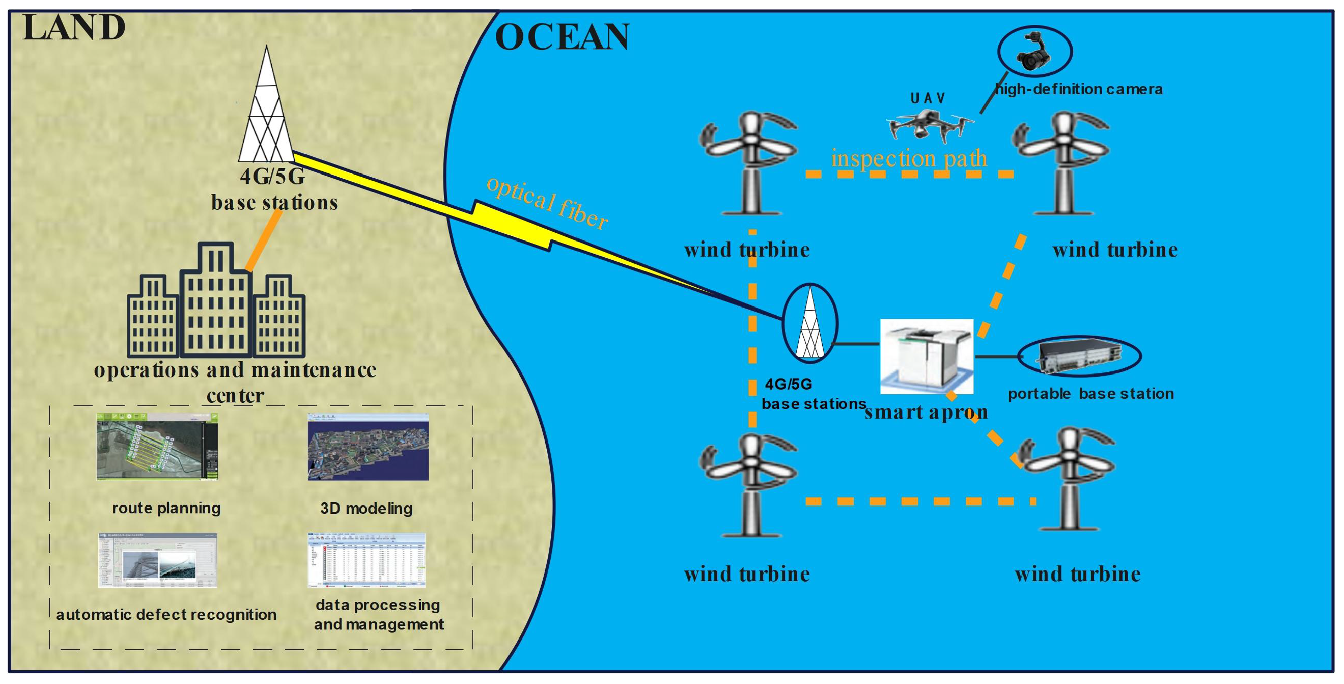
2.1. Fifth Generation Offshore Wind Farm

The 5G Offshore Wind Farm Network is an innovative communications solution tailored to improve the operational efficiency, safety, and intelligence of offshore wind farms. The network utilizes the unique characteristics of 5G communication technology to provide stable and reliable communication services for offshore wind farms, supporting applications such as wind turbine monitoring, data transmission, and remote control (Figure 1).
Among them, the unmanned 5G offshore wind inspection system can complete the monitoring of wind turbine faults [18,19]. And the smart apron becomes a key component of the unmanned inspection system, boasting excellent environmental adaptability and remote control functionality. Connected through a 5G network, the smart apron utilizes edge computing technology to efficiently process the video and data returned from the UAV, providing comprehensive guidance, storage, charging, and data transmission support for UAV operations. The smart apron can either be deployed on the platform of the booster station of an offshore wind farm, or flexibly installed on the nacelle or foundation of a wind turbine.
However, it is inevitable that some challenges will be encountered during UAV inspections. For example, some human-made facilities may constitute obstacle zones, while certain areas may be communication bottlenecks due to weak 5G signal coverage [20,21]. If the UAV fails to effectively avoid these obstacles during its patrol, it may face the risk of an emergency landing or even damage. Especially in deep and distant offshore wind power areas, due to their signal blindness characteristics, even with mobile 5G technology enhancing signal coverage, there may still be areas with weak signal coverage [22]. When the UAV passes through these areas, it may result in the collected data not being able to be fed back to the smart apron in a timely and accurate manner, thus affecting the real-time effectiveness of the inspection.

2.2. Related Research Overview

With the rapid development of clean energy, the scale of offshore wind farms is expanding, and the demand for 5G UAV inspection technology is becoming more and more urgent [23]. Although the traditional UAV path planning has achieved certain results, the special environment of offshore wind farms still requires its adaptive adjustment. The variable wind speed at sea not only threatens the stability of UAV flight, but also directly affects the inspection efficiency; at the same time, the 5G network coverage at sea is not comprehensive, and there are many signal blind zones and unstable areas. Therefore, when performing inspection tasks, UAVs need to accurately plan flight paths, avoid communication-restricted areas, and improve obstacle avoidance capabilities to cope with possible obstacles. How to improve the inspection efficiency of UAVs while considering the influence of sea wind speed and obstacles has become the focus and area of difficulty of the current research on UAV inspection technology for offshore wind farms. For example, Chung et al., in [17], considered the impact of sea wind speed on the inspection efficiency of offshore wind farms and used a D algorithm to improve the inspection efficiency of UAVs, but did not consider the impact of obstacles on UAVs; Lei Xie, in [24], applied the 20-direction A* algorithm to optimize UAV flight paths in offshore wind farm environments. However, this approach overlooked the significant impact of sea wind on UAV flight, which could affect both flight stability and inspection efficiency. As a result, while the path optimization improved, it did not fully address the challenges posed by environmental factors, particularly wind conditions. Yisheng Ji, in [25], fully considered the influence of the environmental terrain function on UAV flight and achieved remarkable results in multiple terrain scenarios. However, the algorithm primarily lacked the capability to handle scenarios involving multiple inspection nodes effectively. Zhang Shuai, in [26], proposed an improved A* algorithm combined with the grid method for obstacle avoidance, while Fan Yang, in [27], introduced an enhanced RRT algorithm. However, both approaches struggled with handling multiple target nodes and solving the TSP effectively; Li Chaoqin proposed a two-phase heuristic algorithm in [28], which solved the TSP by using the simulated annealing algorithm and then used the artificial potential field method to realize obstacle avoidance. Although the algorithm solved the obstacle avoidance problem of UAV inspection well, it was executed in two stages, which was inherently inefficient. Moreover, the distance-based heuristic algorithm might not have been able to achieve the goal of minimizing the time consumption of the inspection line under the current conditions of the UAV speed being affected by sea winds, which was a major consideration. In summary, although these studies have made some progress in UAV inspection of offshore wind farms, there are still some problems and challenges to be solved.
Therefore, based on the actual needs of offshore wind turbine inspection, this paper proposes an application scheme for a 5G UAV in offshore wind turbine inspection by comprehensively considering the various performance limitations of the 5G UAV (including the maximum flight speed, maximum flight time, maximum deflection angle, etc.), as well as the influence of the sea wind speed on the flight efficiency of the UAV, and by combining the characteristics of the offshore environment with fewer obstacles and the limited area of the weak coverage of the 5G signal. Firstly, graphical knowledge is applied to evaluate obstacles among wind turbines, and then SWA-IAGA is innovatively proposed based on the evaluation results. Through this algorithm, the inspection path optimization problem of the 5G UAV is successfully solved, and the shortest inspection time after obstacle avoidance of the UAV is achieved, which greatly improves the inspection efficiency and accuracy of the 5G UAV.

3. Problem Modeling

3.1. Constraints

3.1.1. Fifth Generation UAV

1.
Maximum deflection angle
Since the centripetal force of the UAV when performing circular flight is provided by the tilted lateral force, the smaller the radius of the flight circle is, the larger the curvature of the UAV turning is, which in turn leads to overloading of the UAV. Therefore, the turning angle of the UAV when turning needs to be limited by the maximum deflection angle. Assuming that the actual deflection angle when the UAV is flying is φ i , and the maximum deflection angle of the UAV is φ m a x , then it needs to satisfy
φ i φ m a x
2.
Maximum flight speed
UAVs are limited to a maximum speed of u m a x . Typically, u m a x is referred to as the maximum value of air speed. However, if the UAV is flown at excessively high ground speed, the UAV may not be able to remain stable and the degradation of the structural capabilities of the UAV may result. Therefore, both the air speed and ground speed of the UAV are limited to a maximum value, u m a x , in this paper.
Since the effect of sea wind on UAV flight speed is considered in this paper, it is assumed that the relationship between the UAV’s ground speed s, air-to-air speed v, and sea wind speed w is expressed as s = v + w .
Figure 2 represents the flight status of the UAV when it faces a tailwind and a headwind, while the vector angle between the ground speed s and the wind speed w can be used to determine whether the current UAV flight faces a tailwind or a headwind.
Therefore, the effects of tailwinds and headwinds on the different air speeds of UAVs are taken into account:
Maximum UAV flight speed is satisfied when facing a tailwind:
s = u m a x
Maximum UAV flight speed is satisfied when facing a headwind:
v = u m a x
3.
Maximum flight time
Similarly, considering the battery performance of the UAV, the UAV has an upper limit of flight time t m a x , which is determined by u m a x , and can be obtained by calculating the energy consumption of the UAV [29,30].
4.
Maximum number of inspected turbines
The offshore wind farm operator specifies the maximum number of wind turbines to be inspected per UAV as p.
5.
Safe flight wind conditions
When the wind speed exceeds the maximum drag wind speed ϵ , it may cause the impact of the UAV on the blades of the wind turbine, leading to damage to both, and resulting in the inability of the UAV to perform safe inspections.

3.1.2. Sea Area Condition Information

According to the actual situation of the offshore wind farms, the rectangular sea area (M × N) where the offshore wind farm is located is selected as the target area in this paper. Without loss of generality, the southwest corner of the sea area is chosen as the origin of the coordinate system, where the south side is used as the x-axis and the west side is used as the y-axis. Since the wind turbines generally have the same altitude, it is assumed that the UAVs fly at the same altitude to complete the inspections, and, therefore, the z-axis is ignored, and a two-dimensional planar Cartesian coordinate system is constructed, thus more accurately describing and locating the position of the points within the task area.
At the same time, the planning target area is constructed by the raster method, where the raster image grain edge length is Δ . According to the actual obstacles in the maritime environment as well as the obstacle zones of the weak 5G coverage, each obstacle zone is simplified to a circle and filled with an approximation using a raster, and the UAV avoids the obstacles by flying around them. To this end, the traditional 0-1 assignment method is discarded (the grids with obstacles are assigned a value of 1, and the ones that do not contain them are assigned a value of 0), and the concept of the grids’ danger is adopted to design the obstacle impact matrix E (with the size of (M/ Δ ) × (N/ Δ )). The elements in E are in a one-to-one correspondence with the coordinates of the grids, and the values of the elements in E corresponding to the grids where the obstacle zones are located are assigned a value of 1. The obstacle zone impact radius R is designed, and the element in E corresponding to the raster within the radius of influence of the obstacle area takes the value σ :
σ = e r 2 R / 2
where R is the radius of influence of the obstacle zone and r is the Euclidean distance of the element corresponding to the actual node of the obstacle zone. The grid outside the radius of influence of the obstacle area is an obstacle-free grid, and its corresponding element in E takes the value of 0.
The offshore wind farm environment usually has fewer obstacle buildings, and under 5G communication technology, there are fewer areas with weak coverage of communication signals in the offshore wind farm area, so E is usually a sparse matrix.

3.2. Problem Modeling

1.
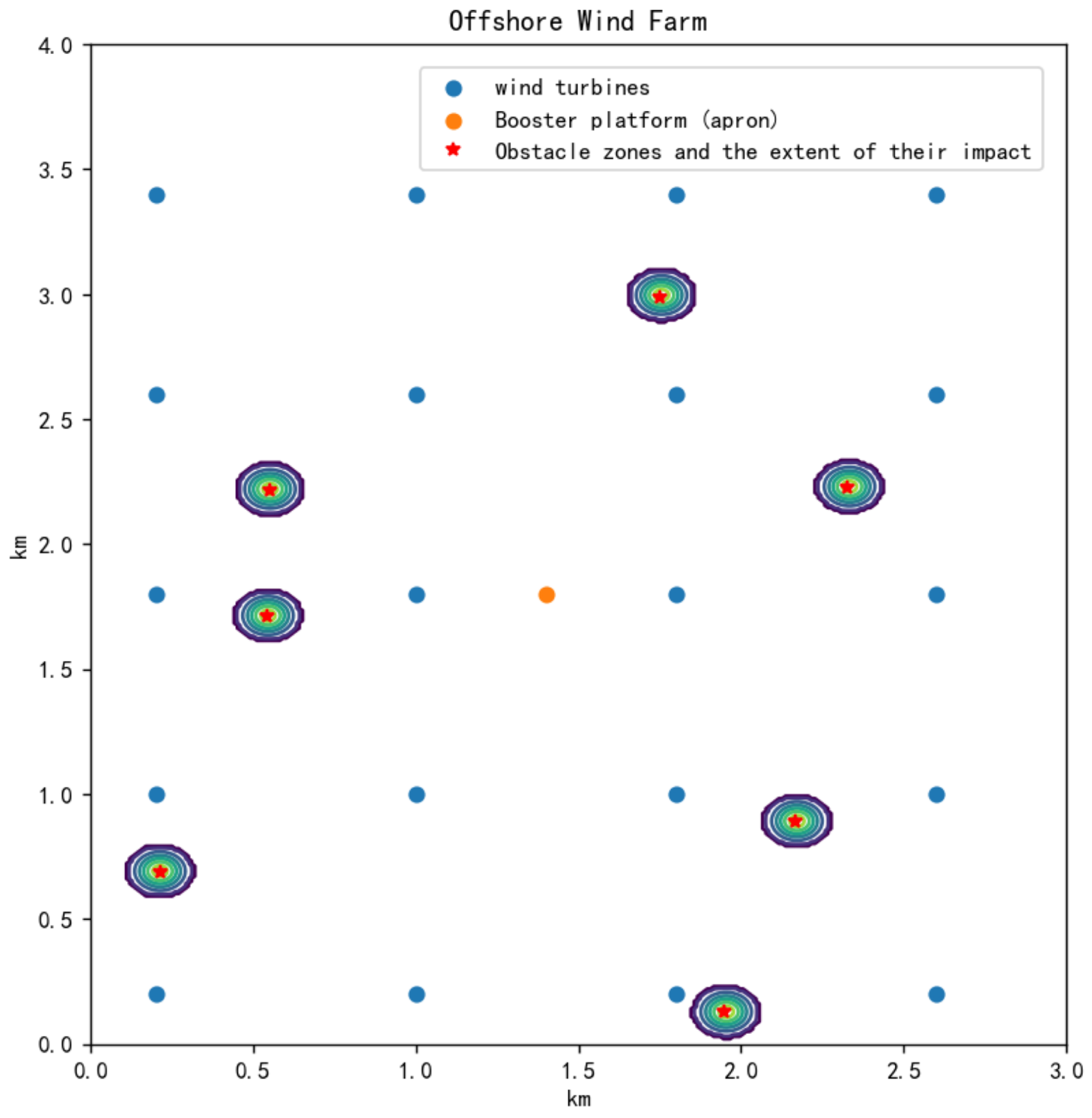
Offshore wind farm environment modeling
By inputting the boundary conditions, such as the coordinates of the wind turbine group positions of the offshore wind farm, the offshore terrain information, and the 5G coverage area, into the system, combined with the information of the UAV machine’s own flight constraints, as well as the operator’s stipulation of the maximum number of wind turbines to be inspected by each UAV, the server automatically patrols the range of the line for each 5G UAV.
Therefore, according to the environmental characteristics of offshore wind farms and the 5G UAV’s own condition constraints, this paper sets up T wind turbines with coordinates q k = [ x k , y k ] , k 0 , 1 , 2 , , T 1 , one smart apron located at the boosting platform with coordinate q s = [ x s , y s ] , and the obstacle zone information (including the coordinate position q o = [ x o , y o ] of the center for each obstacle zone, and the radius R of the area of influence of each obstacle).
Figure 3 shows the offshore wind farm environmental model, in which the blue solid circle indicates the location of the turbine, the orange solid circle indicates the location of the smart apron, and the star shape and its outer contour circle indicate the obstacle area and the range of potential impacts it generates. The parameters are designed as follows: a 3 km × 4 km rectangular mission area at sea, the total number of turbines, T = 20, and the location coordinates of the smart apron of the booster station, (1.4, 1.8) (km).
2.
Fifith generation UAV group task allocation
The 5G UAV group patrol task assignment problem is a typical Vehicle Routing Problem (VRP). In the context of multi-UAV patrol task assignment, the VRP is concerned with optimizing the patrol path of UAVs to efficiently visit individual wind turbines (as different customers), complete the tour, and return to the apron while minimizing the total distance traveled or cost.
Mathematically, the objective function can be expressed as
min k = 1 K i = 0 n j = 0 n c i j x i j k
where K is the number of UAVs, c i j represents the cost of traveling from i-th wind turbine to j-th wind turbine, and x i j k is a binary variable indicating whether UAV k travels from i-th wind turbine to j-th wind turbine.
To ensure feasibility, the optimization is subject to the following constraints:
(a)
Coverage constraint: each wind turbine is visited exactly once:
k = 1 K i = 0 n x i j k = 1 , j { 1 , , n }
(b)
Continuity constraint: the path of each UAV must be continuous:
j = 0 n x i j k j = 0 n x j i k = 0 , k { 1 , , K } , i { 1 , , n }
(c)
Capacity constraint: the total number of wind turbines assigned to each UAV must not exceed p.
(d)
Flight capability constraint: the flight time of each UAV cannot exceed its maximum battery capacity t m a x :
i = 0 n j = 0 n t i j x i j k t m a x , k { 1 , , K }
where t i j represents the travel time between i-th wind turbine and j-th wind turbine.
Solving such VRPs typically requires optimization algorithms. The method in this paper refers to the approach in reference [31], which applies genetic algorithms to assign inspection tasks for multiple UAVs. By leveraging this approach, the proposed method ensures that each UAV efficiently completes its inspection tasks while minimizing operation costs and improving work efficiency.
3.
Modeling of 5G UAV line patrol path optimization problem after task assignment
After completing the inspection task assignment of the 5G UAV, the airport located at the booster pad releases the UAV for blade inspection, and designs the inspection route of the 5G UAV based on the position of the coordinates of the wind turbines to be inspected that have been assigned to the current 5G UAV k. The inspection problem of the 5G UAV k is the classic TSP—a UAV needs to inspect t turbines, and the UAV is required to start from the booster station (where the smart apron is located), inspect each turbine once, and then return to the starting turbine, ensuring that the chosen path has the shortest time.
Therefore, we define the graph G = T , B , where T is the set of all wind turbines within the patrol range of UAV k (set size is t), and B is the set of paths connecting each wind turbine, where t is the total number of turbines within the patrol range of UAV k, and b is the set of paths connecting each turbine and between the turbines and the apron. Using the structure of the graph, we create an adjacency matrix D ij , of size (t + 1) × (t + 1), where the elements in the i-th row and j-th column of D ij take the value of d ij , i.e., the flight time of the UAV from the i-th wind turbine to the j-th wind turbine, and the value of d ij is different from the value of d ji , in consideration of the influence of the sea wind on the ground speed of the UAV’s flight, i.e., G is an asymmetric graph and D ij is an asymmetric adjacency matrix. In other words, the core of the current UAV path planning problem lies in designing effective algorithms to populate the asymmetric adjacency matrix D ij and selecting elements from the matrix according to a specific condition (minimizing the total flight time) in order to form an optimal path for the UAV from the starting turbine to the target turbine.

4. SWA-IAGA: Sea Wind-Aware Improved A*-Guided Genetic Algorithm

In this section, we propose the SWA-IAGA, which uses the improved A* algorithm to guide the genetic algorithm, with support from graphical knowledge. The algorithm plans an inspection path for the wind turbines assigned to UAV k, taking into account the effect of sea wind on its flight.

4.1. An Improved A* Algorithm

In this section, an improved A* algorithm is used to help UAV k to achieve the goal of line patrolling and obstacle avoidance, and the algorithm optimizes the node expansion algorithm of the traditional A* algorithm to smooth the route of path planning, and also adds the danger factor w, which improves the evaluation function of the traditional A* algorithm, which avoids the problem that the route is tightly adhering to obstacle areas.

4.1.1. Principle of the Algorithm

1.
Circular node expansion method
Reference [26] proposes a node expansion method different from the classical A* algorithm. The circular node expansion method allows the nodes to be expanded in any direction around the current node based on the number of nodes to be selected when determining the location of the next node, instead of being limited only to the center of the eight squares around the traditional A* algorithm in combination with the grid method.
2.
Evaluation function
The evaluation function of the A* algorithm is f ( n ) = g ( n ) + h ( n ) , where f ( n ) is the comprehensive cost, which is the basis for the selection of the next node; g ( n ) is the actual cost from the starting node to node n; and h ( n ) is the estimated cost from node n to the target node calculated by the heuristic function.
Considering the criterion of path optimization, the 5G UAV achieves the shortest patrol planning time under the premise of obstacle avoidance; the flight time of the UAV is selected as the value of the evaluation function, i.e., g ( n ) is the actual flight time from the starting node to the current node; and h ( n ) is the predicted flight time for the Euclidean distance d from node n to the target node of the UAV.
3.
Improved evaluation function
During the search process of the classical A* algorithm, the evaluation function for the nodes to be selected only takes into account the time cost and whether or not they are within the obstacle zone, which may result in the UAV planning a route that closely follows the obstacle zone.
To solve this problem, this paper also improves the evaluation function of the classical A* algorithm:
f ( n ) = g ( n ) + w h ( n )
where w is the hazard factor and its value is
w = tan π 2 σ + 1
where σ is the barrier impact factor whose value is equal to the value of the element in matrix E corresponding to node n.
Therefore, the UAV, with respect to the obstacle zone, can make an avoidance response in advance, avoiding the problem of the route being planned close to the obstacle zone.

4.1.2. A* Algorithm Search Path Process

  • Initialization: create an open list (OL) with the starting point A and a close list (CL) for explored nodes.
  • Expansion and evaluation: remove the node N with the smallest evaluation function value from the open list and add it to the close list. Explore the neighbors of N by using circular node expansion method. For each neighbor M, if M is not in the CL, calculate g(M) (actual cost from start to M) and h(M) (estimated cost from M to end), and combine this with the hazard factor w to calculate f ( M ) = g ( M ) + w h ( M ) (evaluation function). If M is not in the open list, add it to the open list and set N as its parent node.
  • Update path: if M is already in the OL, compare the path through N with the existing path. If the new path is better (lower g(M)), update M’s parent and re-evaluate f(M).
  • Cyclic exploration: repeat steps (b) and (c), selecting the node with the lowest evaluation function value from the OL until the end point is found or the open list is empty (indicating no reachable path).
  • Construct path: once the end point is in the CL, backtrack from the end point to the start point via parent nodes to construct the shortest path.
Figure 4 shows the flow of the A* algorithm search path process algorithm.
After reaching the target node, the g ( n ) value of the target node is returned, i.e., the UAV flight time for the path planned by the A* algorithm.

4.2. Genetic Algorithm

In this paper, a genetic algorithm (GA) is used to solve the traveling salesman problem.
For solving the TSP of UAV k with the genetic algorithm, the patrol path is the arrangement of the smart apron to t wind turbines and then to the smart apron. In this paper, we use genetic coding to represent the patrol path, for example, the patrol (0-5-6-4-2-1-3-0) can be represented as a chromosome gene combination (0 5 6 4 2 1 3 0).
The core steps of the GA include initialization of the population, computation of the fitness function, selection operation, crossover operation, mutation operation, and iterative evolution.
Since the goal of the patrol is to have the shortest patrol time, according to the adjacency matrix D ij , the fitness function is
f ( w 0 , w 1 , , w t , w 0 ) = 1 i = 0 t 1 D ( w i , w i + 1 ) + D ( w t , w 0 )
where w 0 is the Booster Station Smart Apron serial number, and w 1 , w 2 , , w t are the serial numbers of the turbines to be inspected in the path of the UAV patrol.

4.3. Knowledge of Graphics

In the asymmetric adjacency matrix D ij , the element d ij represents the flight time of a UAV from the i-th wind turbine to the j-th wind turbine. Due to the sparsity of the obstacle impact matrix E, obstacles encountered during straight-line flight between two wind turbines are rare. Graphics methods are used to detect the presence of obstacles between the i-th and j-th wind turbines to efficiently populate the matrix D ij : if there are no obstacles, the UAV will fly in a straight line, and the value of d ij will be the Euclidean distance between the two wind turbines divided by the UAV’s ground speed; if there is an obstacle, the improved A* algorithm will be applied to plan an obstacle avoidance route, starting from the i-th wind turbine and ending at the j-th turbine, and the flight time is used as the d ij value to fill in the matrix.
The coordinates of grid A where the i-th wind turbine is located are set to be [ x i , y i ] , and the coordinates of grid B where the j-th wind turbine is located are set to be [ x j , y j ] . The principle of the algorithm for checking for the existence of an obstacle area between two wind turbines is as follows:
  • Find all rasters touched by line segment AB.
    (a)
    Transformation: Translate and flip (if necessary) the line segment AB to obtain a line segment in the first quadrant, starting at the origin, and use k < = 1 for subsequent raster determination.
    (b)
    Traverse the line segment AB and determine the contact grid:
    Traverse the points on the transformed line segment AB in the x-direction in increments of 0.5 Δ ( Δ is the edge length of the raster metaparticle), where the coordinate of the n-th point is [ n × 0.5 Δ , n × 0.5 Δ × k ] . For each point, perform the following judgment. If n is even: if the point is located on the boundary of the raster, the left and right rasters adjacent to the point are judged as being touched by the line segment AB. If n is odd: if the point is in the grid, the grid containing the point is judged as the contact grid; if the point is located on the boundary of a grid, the upper and lower grids are judged for contact with the line segment AB.
    (c)
    Inverse transformation: After completing the above judgment, we need to convert the obtained contact raster coordinates from the transformed coordinate system back to the original coordinate system. This involves inverse rotation and inverse translation operations on the coordinates to restore the position and direction of the line segment AB in the original space.
  • Judge whether the values of the elements in the corresponding E of the line segment contact raster are all 0. If they are all 0, then it is judged that there is no obstacle zone between wind turbine i and wind turbine j. If they are not all 0, then it means that at least one of the rasters contains obstacles, and, therefore, it can be judged that there is an obstacle zone between wind turbine i and wind turbine j, and the UAV needs to take obstacle avoidance measures.
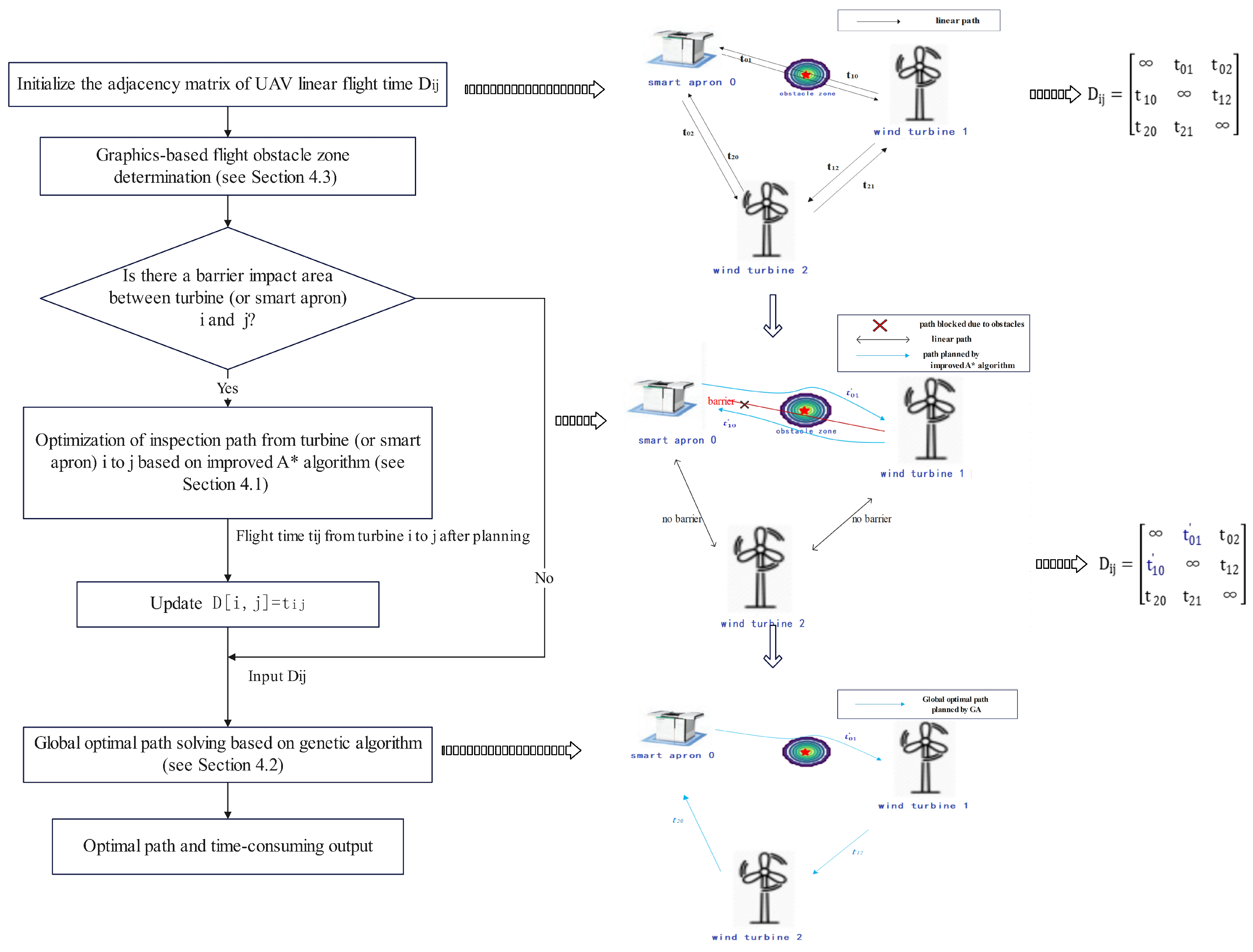
4.4. SWA-IAGA

1.
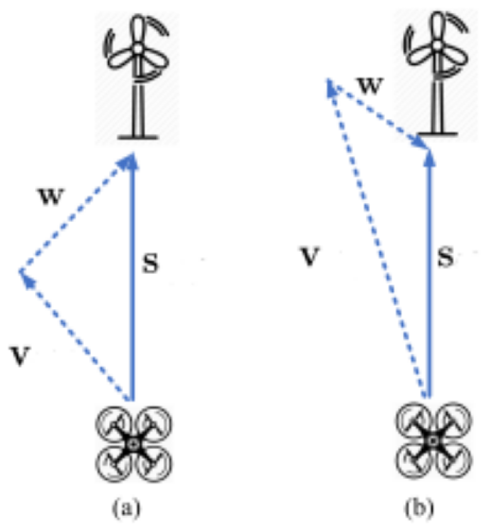
Flight speed modeling and asymmetric adjacency matrix creation considering the effect of sea wind
The current sea wind speed data are collected, and the straight-line flight time of the UAV between different wind turbines is calculated based on the flight performance parameters of the UAV k (e.g., wind resistance, maximum flight speed, etc.) as the element of the matrix d ij .
2.
Consideration of graphics-based flight obstacle zone determination
Utilize the offshore Geographic Information System (GIS)data to construct the flight environment model between the turbines. Adopt the collision detection algorithm in graphics to judge whether UAV k will encounter a flight obstacle zone on a straight path. If there is an obstacle zone, record the tuple of turbine coordinates ( q i , q j ) involving the obstacle zone and add it to the list of planned paths.
3.
Obstacle avoidance path planning and flight time updating with improved A* algorithm
For each pair of turbines in the planning path list, the improved A* algorithm is utilized for obstacle avoidance path planning under the consideration of the sea wind effect, and the flight time after obstacle avoidance is returned to update the asymmetric adjacency matrix.
4.
Global optimal flight path solving based on genetic algorithm
Take the updated D ij as input and construct the fitness function of the genetic algorithm. Initialize the population of the genetic algorithm, with each individual representing a possible combination of flight paths, followed by the design of suitable genetic operations (e.g., selection, crossover, and mutation) to gradually optimize the flight paths during the iteration process. The total elapsed time of each individual in the population is calculated in each iteration of the genetic algorithm, and the fitness evaluation is performed based on the total elapsed time, and finally the optimal flight path with the shortest total elapsed time is gradually approximated through multi-generation evolution.
In conclusion, the flow design of the SWA-IAGA is shown in Figure 5.

5. Simulation and Results Analysis

The hardware configuration of the experimental environment is Intel(R) Core(TM) i5-7300HQ CPU @2.50GHz, 8 GB RAM, sourced from Beijing, China. the software environment is configured with Windows 10, and the algorithm is implemented using Python 3.9 programming.

5.1. Fifth Generation UAV Group Patrol Task Assignment

In this simulation, we set up a sea rectangle task area (M × N) where M takes the value of 3 km and N takes the value of 4 km. The total number of wind turbines is T = 20. The coordinates of the location of the smart apron of the booster are (1.4, 1.8) (km). We set up seven flight obstacle areas, the obstacle impact radius is set to 100 m, and the obstacle center coordinates list as [(0.544, 1.710), (2.165, 0.890), (1.948, 0.129), (2.326, 2.225), (0.550, 2.215), (0.213, 0.690), (1.750, 2.989)] (km).
The parameters of the 5G UAV used in the simulation are designed to have a maximum speed limit u m a x of 16 m/s and a maximum flight time t m a x of 120 min. Each UAV can be assigned to check up to p = 5 turbines.
For the patrol task assignment for the 5G UAV group, we use the method in reference [31].
The simulation results indicate that four UAVs are required to accomplish the inspection task in this sea area in the scenario of this paper. Figure 6 shows the patrol range allocation of these UAVs, where the solid circle represents the coordinates of the smart apron of the UAVs and the location coordinates of the turbines, and the star shape and its outer contour circle represent the obstacle area and its possible impact range.

5.2. SWA-IAGA for UAV Path Planning

The 5G UAV2 assigned in Section 5.1 is selected for path planning using the SWA-IAGA, and the simulation results are analyzed. From Section 5.1, the number of turbines to be inspected by 5G UAV2 is five. The UAV starts its inspection from the smart apron of the booster platform (set the location coordinates of the booster platform to be (1.4, 1.8) and set the id to be 0). The locations and ids of wind turbines to be inspected are shown in Figure 7.
It is assumed that the current wind speed in the sea area is 5 m/s and the wind angle is 2/5 π ; the location of the booster station, the center of the obstacle zone, and the radius of influence of the obstacle zone are the same as in Section 5.1. The parameters of the 5G UAV used in the simulation are designed to have a maximum speed limit u m a x of 16 m/s, a maximum flight time t m a x of 120 min, and a maximum deflection angle of 3/4 π .
The parameters in the SWA-IAGA are as follows: the nodes to be selected for the circular node method are 16 nodes, the pathfinding step size is 0.01 km, the number of individuals in the genetic algorithm is 60, the number of iteration rounds is 400, and the probability of variation is 0.25.
Considering the influence of the sea wind on the UAV, the simulation outputs the UAV inspection route as a directed route, and the order of inspection of the turbines is 0->4->2->5->3->1->0. The simulation experiment also outputs the expected UAV flight duration of this route: 94 min 27 s.
In order to further verify the effectiveness of the algorithms proposed in this study, for the examples in this paper, the optimal paths are calculated using the following: (1) the SWA-IAGA; (2) the two-stage heuristic algorithm based on the artificial potential field method and the simulated annealing algorithm in reference [28] (APF-SA); and (3) the two-stage heuristic algorithm of the A* algorithm and the genetic algorithm (A*-GA). Comparison is carried out, and the results of the experimental comparison are as follows.
In Figure 7, we show the trajectory comparison plots of the three different algorithms. Of particular interest is the SWA-IAGA, which fully considers the effect of sea wind when planning the inspection sequence. According to the design of the algorithm, the inspection order is 0->4->2->5->3-1->0. In contrast, the other two algorithms have an inspection order of 0-4-1-2-5-3-0, and there is no specific design of the inspection order direction because the sea wind factor is not taken into consideration. And it can be clearly seen through the comparison diagram that the algorithm proposed in this study shows significant advantages in trajectory planning. The algorithm is designed with full consideration of the influence of sea wind, and generates a smoother inspection trajectory through an innovative heuristic strategy. This smoother trajectory not only effectively reduces the inspection efficiency reduction and safety hazards caused by the sea wind interference, but also significantly improves the stability and reliability of the inspection work.
By comparing the trajectory plots after zooming in (Figure 7), the algorithm proposed in this study has better accuracy in avoiding obstacle zones by avoiding crossing the center of the obstacle or other potentially risky areas. In contrast, although Algorithm (2) (APF-SA) and Algorithm (3) (A*-GA) also have some obstacle avoidance ability in trajectory planning, when dealing with specific obstacles, such as the obstacle zone located at (0.213, 0.69), Algorithm (2) (APF-SA) appeared to fit on the edge of the obstacle zone, which increased the risk during the inspection process, and Algorithm (3) (A*-GA) responded to obstacle zones with avoidance too early, which affected the flight efficiency.
In addition, in order to evaluate the performance of the three algorithms more comprehensively, we also comparatively analyzed their patrol time consumption. Since the effect of sea wind is not taken into account, Algorithm (2) (APF-SA) and Algorithm (3) (A*-GA) will lead to different inspection times when different inspection directions are selected; the minimum inspection time of these two algorithms is selected as the benchmark for comparison during the comparison process.
In order to verify the effectiveness of this paper’s algorithms under different sea wind conditions, comparative experiments were conducted in this paper. Different groups of sea wind speeds and wind angles were set up, and the three algorithms mentioned above were applied to UAV2 for the comparative analysis of patrol time (Figure 8).
Then, based on the task allocation strategy described in Section 5.1, simulation experiments were conducted on the four 5G UAVs in turn, aiming to complete the path optimization task. In this process, a comparative analysis of the three algorithms was also implemented separately for each UAV, thus obtaining their patrol time data under different conditions (Figure 9).
As can be seen in Figure 8 and Figure 9, the SWA-IAGA (Algorithm (1)) demonstrates remarkable superiority compared to other algorithms across diverse UAV inspection tasks, including varying wind turbines and obstacle zone distributions, and under different sea wind conditions. Statistical analysis further confirms this superiority: paired t-tests reveal that Algorithm (1) (SWA-IAGA) achieves significantly shorter inspection times compared to Algorithm (2) (APF-SA) and Algorithm (3) (A*-GA) (p < 0.05) across all tested scenarios, including different UAVs and wind conditions. This indicates that Algorithm (1) (SWA-IAGA) effectively reduces unnecessary inspection time consumption, significantly improves inspection efficiency, and exhibits superior performance in practical applications, which not only helps improve work efficiency, but also helps to reduce operating costs.
To further validate the applicability of Algorithm (1) and emphasize the advantages of the SWA-IAGA in UAV path planning, an additional simulation scenario was designed. This scenario involved doubling the UAV battery capacity and randomly adding obstacle zones to increase the environmental complexity. With only two UAVs deployed in the wind farm, each tasked with inspecting 10 turbines starting from the booster platform apron, the simulation results (Figure 10) reveal that the SWA-IAGA consistently achieves significant reductions in inspection time, even under increased task loads and additional obstacle zones. These findings further underscore the robustness and efficiency of the SWA-IAGA in tackling complex UAV inspection tasks.
In summary, the SWA-IAGA proposed in this paper demonstrates excellent performance in the UAV inspection path optimization problem based on the full consideration of the influence of sea wind. The algorithm can not only accurately assess the impact risk of the obstacle region, thus ensuring that the UAV achieves efficient obstacle avoidance during the inspection process, but also effectively reduces the inspection time, significantly improves the inspection efficiency, and realizes the effectiveness and rationalization of resource utilization.

6. Conclusions

In the current context of energy transition, the safety and operational efficiency of offshore wind power, as an important part of clean energy, is increasingly of concern. In order to meet this challenge, this paper conducts an in-depth study on the 5G UAV path optimization problem for unmanned inspection of offshore wind power, aiming to improve the inspection efficiency and accuracy of UAVs and ensure the safe operation of wind farms.
In order to achieve the goal of minimizing the inspection route time after obstacle avoidance for the UAV, we propose the SWA-IAGA: an improved A*-guided genetic algorithm, which utilizes graphical knowledge and considers the influence of sea wind on the UAV’s flight speed.In the simulation experiment, the algorithm is able to calculate the optimal inspection route by considering obstacle avoidance efficiency and time optimization in the complex offshore wind power environment. Thus, unnecessary flight time and energy waste are avoided.
Although the method proposed in this paper demonstrates notable advantages in path planning for 5G unmanned aerial vehicles (UAVs) in complex offshore wind farm environments, it still encounters some challenges in practical applications, such as the incomplete consideration of issues like UAV task data offloading, efficient data transmission, and multi-UAV coordination. To further enhance the practicality and efficiency of the algorithm, future research can continue to delve deeper into these critical aspects, aiming to optimize the algorithm’s performance and promote the widespread application and sustainable development of UAVs in offshore wind farm inspection and other relevant fields.

Author Contributions

Conceptualization, F.X. and W.H.; methodology, W.H.; software, C.J.; validation, J.Z., W.H. and F.X.; formal analysis, J.Z.; investigation, J.Z.; resources, J.Z.; data curation, F.X.; writing—original draft preparation, W.H.; writing—review and editing, C.J.; visualization, L.Y.; supervision, Y.G.; project administration, F.X.; funding acquisition, C.J., L.Y., Y.G., J.Z. and F.X. All authors have read and agreed to the published version of the manuscript.

Funding

This research was funded by PowerChina Huadong Engineering Corporation Limited under the project Offshore Wind Power 5G Key Technology Research and Product Development.

Data Availability Statement

The data presented in this study are available on request from the corresponding author.

Conflicts of Interest

Authors Congxiao Jiang, Lingang Yang, Yuqing Gao and Jie Zhao were employed by PowerChina Huadong Engineering Corporation Limited. The authors declare that they have no known competing financial interests or personal relationships that could have appeared to influence the work reported in this paper.

Abbreviations

The following abbreviations are used in this manuscript:
TSPtraveling salesman problem
UAVunmanned aerial vehicle
GISGeographic Information System

References

  1. Huang, X.; Wang, G.; Lu, Y.; Jia, Z. Study on a Boat-Assisted Drone Inspection Scheme for the Modern Large-Scale Offshore Wind Farm. IEEE Syst. J. 2023, 17, 4509–4520. [Google Scholar] [CrossRef]
  2. Xing, X. Fully digital wind farm monitoring and inspection system based on AR augmented reality technology. IOP Conf. Ser. Earth Environ. Sci. 2020, 440, 032008. [Google Scholar] [CrossRef]
  3. Wang, L.; Zhang, Z. Automatic detection of wind turbine blade surface cracks based on UAV-taken images. IEEE Trans. Ind. Electron. 2017, 64, 7293–7303. [Google Scholar] [CrossRef]
  4. Khan, S.K.; Farasat, M.; Naseem, U.; Ali, F. Performance evaluation of next-generation wireless (5G) UAV relay. Wirel. Pers. Commun. 2020, 113, 945–960. [Google Scholar] [CrossRef]
  5. Geraci, G.; Garcia-Rodriguez, A.; Azari, M.M.; Lozano, A.; Mezzavilla, M.; Chatzinotas, S.; Chen, Y.; Rangan, S.; Di Renzo, M. What will the future of UAV cellular communications be? A flight from 5G to 6G. IEEE Commun. Surv. Tutor. 2022, 24, 1304–1335. [Google Scholar] [CrossRef]
  6. Mwangi, A.; Sahay, R.; Fumagalli, E.; Gryning, M.; Gibescu, M. Towards a Software-Defined Industrial IoT-Edge Network for Next-Generation Offshore Wind Farms: State of the Art, Resilience, and Self-X Network and Service Management. Energies 2024, 17, 2897. [Google Scholar] [CrossRef]
  7. Nomikos, N.; Gkonis, P.K.; Bithas, P.S.; Trakadas, P. A survey on UAV-aided maritime communications: Deployment considerations, applications, and future challenges. IEEE Open J. Commun. Soc. 2022, 4, 56–78. [Google Scholar] [CrossRef]
  8. Li, B.; Fei, Z.; Zhang, Y. UAV Communications for 5G and Beyond: Recent Advances and Future Trends. IEEE Internet Things J. 2019, 6, 2241–2263. [Google Scholar] [CrossRef]
  9. Yao, Q.; Zheng, Z.; Qi, L.; Yuan, H.; Guo, X.; Zhao, M.; Liu, Z.; Yang, T. Path planning method with improved artificial potential field—A reinforcement learning perspective. IEEE Access 2020, 8, 135513–135523. [Google Scholar] [CrossRef]
  10. Platanitis, K.S.; Kladis, G.P.; Petrongonas, E.; Skliros, C.; Tsourveloudis, N.C.; Zagorianos, A.D. UAV path planning for offshore swarm-based missions. In Proceedings of the 2022 International Conference on Unmanned Aircraft Systems (ICUAS), Dubrovnik, Croatia, 21–24 June 2022; pp. 124–133. [Google Scholar]
  11. Li, X.; Feng, W.; Wang, J.; Chen, Y.; Ge, N.; Wang, C.X. Enabling 5G on the ocean: A hybrid satellite-UAV-terrestrial network solution. IEEE Wirel. Commun. 2020, 27, 116–121. [Google Scholar] [CrossRef]
  12. Li, J.; Liu, W.; Han, Y.; Xing, H.; Yang, A.; Pan, Y. TSP Problem Based on Artificial Ant Colony Algorithm. In Lecture Notes in Real-Time Intelligent Systems; Springer: Cham, Switzerland, 2018; pp. 196–202. [Google Scholar]
  13. Chen, T.; Zhang, G.; Hu, X.; Xiao, J. Unmanned aerial vehicle route planning method based on a star algorithm. In Proceedings of the 2018 13th IEEE Conference on Industrial Electronics and Applications (ICIEA), Wuhan, China, 31 May–2 June 2018; pp. 1510–1514. [Google Scholar]
  14. Ait Saadi, A.; Soukane, A.; Meraihi, Y.; Benmessaoud Gabis, A.; Mirjalili, S.; Ramdane-Cherif, A. UAV path planning using optimization approaches: A survey. Arch. Comput. Methods Eng. 2022, 29, 4233–4284. [Google Scholar] [CrossRef]
  15. Cheng, C.; Sha, Q.; He, B.; Li, G. Path planning and obstacle avoidance for AUV: A review. Ocean. Eng. 2021, 235, 109355. [Google Scholar] [CrossRef]
  16. Zhang, W.; Wang, N.; Wu, W. A hybrid path planning algorithm considering AUV dynamic constraints based on improved A* algorithm and APF algorithm. Ocean. Eng. 2023, 285, 115333. [Google Scholar] [CrossRef]
  17. Chung, H.M.; Maharjan, S.; Zhang, Y.; Eliassen, F.; Strunz, K. Placement and routing optimization for automated inspection with unmanned aerial vehicles: A study in offshore wind farm. IEEE Trans. Ind. Inform. 2020, 17, 3032–3043. [Google Scholar] [CrossRef]
  18. Fahim, M.; Sharma, V.; Cao, T.V.; Canberk, B.; Duong, T.Q. Machine learning-based digital twin for predictive modeling in wind turbines. IEEE Access 2022, 10, 14184–14194. [Google Scholar] [CrossRef]
  19. Zhou, Y.; Chen, J.; Xu, R.; Cao, Z.; Jin, Z.; Guo, Z.; Wang, W.; Li, K. Three dimensional fully autonomous inspection method for wind power employing unmanned aerial vehicle based on 5G wireless communication and artificial intelligence. In Proceedings of the 2022 IEEE 5th Advanced Information Management, Communicates, Electronic and Automation Control Conference (IMCEC), Chongqing, China, 16–18 December 2022; Volume 5, pp. 800–805. [Google Scholar]
  20. Elnabty, I.A.; Fahmy, Y.; Kafafy, M. A survey on UAV placement optimization for UAV-assisted communication in 5G and beyond networks. Phys. Commun. 2022, 51, 101564. [Google Scholar] [CrossRef]
  21. Huo, Y.; Dong, X.; Lu, T.; Xu, W.; Yuen, M. Distributed and multilayer UAV networks for next-generation wireless communication and power transfer: A feasibility study. IEEE Internet Things J. 2019, 6, 7103–7115. [Google Scholar] [CrossRef]
  22. Tang, G.; Tang, C.; Claramunt, C.; Hu, X.; Zhou, P. Geometric A-star algorithm: An improved A-star algorithm for AGV path planning in a port environment. IEEE Access 2021, 9, 59196–59210. [Google Scholar] [CrossRef]
  23. Wang, Z.; Guo, Y.; Wang, H. Review on monitoring and operation-maintenance technology of far-reaching sea smart wind farms. J. Mar. Sci. Eng. 2022, 10, 820. [Google Scholar] [CrossRef]
  24. Xie, L.; Xue, S.; Zhang, J.; Zhang, M.; Tian, W.; Haugen, S. A path planning approach based on multi-direction A* algorithm for ships navigating within wind farm waters. Ocean. Eng. 2019, 184, 311–322. [Google Scholar] [CrossRef]
  25. Ji, Y.; Zhao, X.; Hao, J. A Novel UAV Path Planning Algorithm Based on Double-Dynamic Biogeography-Based Learning Particle Swarm Optimization. Mob. Inf. Syst. 2022, 2022, 8519708. [Google Scholar] [CrossRef]
  26. Zhang, S.; Li, X.; Zhang, P.; Li, B. UAV path planning based on improved A* algorithm. Comput. Syst. Appl. 2021, 34, 39–43. [Google Scholar]
  27. Yang, F.; Fang, X.; Gao, F.; Zhou, X.; Li, H.; Jin, H.; Song, Y. Obstacle Avoidance Path Planning for UAV Based on Improved RRT Algorithm. Discret. Dyn. Nat. Soc. 2022, 2022, 4544499. [Google Scholar] [CrossRef]
  28. Li, C.; Peng, X. Two-stage Path Optimization of UAVs Patrol on Transmission Towers Considering Obstacle Avoidance. Comput. Meas. Control 2019, 27, 159. [Google Scholar]
  29. Khan, A.; Zhang, J.; Ahmad, S.; Memon, S.; Qureshi, H.A.; Ishfaq, M. Dynamic positioning and energy-efficient path planning for disaster scenarios in 5G-assisted multi-UAV environments. Electronics 2022, 11, 2197. [Google Scholar] [CrossRef]
  30. Fan, T.; Fu, L.; Guo, C.; Zhang, Y.; Sun, L. Multi UAV Inspection Optimization for Offshore Wind Farms Considering Battery Exchange Process. IEEE Trans. Intell. Veh. 2024, 1–11. [Google Scholar] [CrossRef]
  31. Baker, B.M.; Ayechew, M. A genetic algorithm for the vehicle routing problem. Comput. Oper. Res. 2003, 30, 787–800. [Google Scholar] [CrossRef]
Figure 1. Fifth generation offshore wind farm unmanned inspection system.
Drones 09 00047 g001
Figure 2. Relationship between UAV air speed, ground speed, and wind speed in (a) tailwind and (b) headwind.
Drones 09 00047 g002
Figure 3. Environmental modeling of offshore wind farms.
Drones 09 00047 g003
Figure 4. Flowchart of the improved A* algorithm.
Drones 09 00047 g004
Figure 5. Flowchart of the SWA-IAGA.
Drones 09 00047 g005
Figure 6. Fifth generation UAV group inspection task assignment.
Drones 09 00047 g006
Figure 7. Algorithm comparison of optimal patrol route outputs.
Drones 09 00047 g007
Figure 8. Comparison statistics of inspection time consumed by UAV2 with different algorithms under different sea wind conditions.
Drones 09 00047 g008
Figure 9. Comparison statistics of inspection time consumed by 4 UAVs with different algorithms.
Drones 09 00047 g009
Figure 10. Extended validation: algorithm comparison of optimal patrol route outputs and inspection time.
Drones 09 00047 g010
Disclaimer/Publisher’s Note: The statements, opinions and data contained in all publications are solely those of the individual author(s) and contributor(s) and not of MDPI and/or the editor(s). MDPI and/or the editor(s) disclaim responsibility for any injury to people or property resulting from any ideas, methods, instructions or products referred to in the content.

