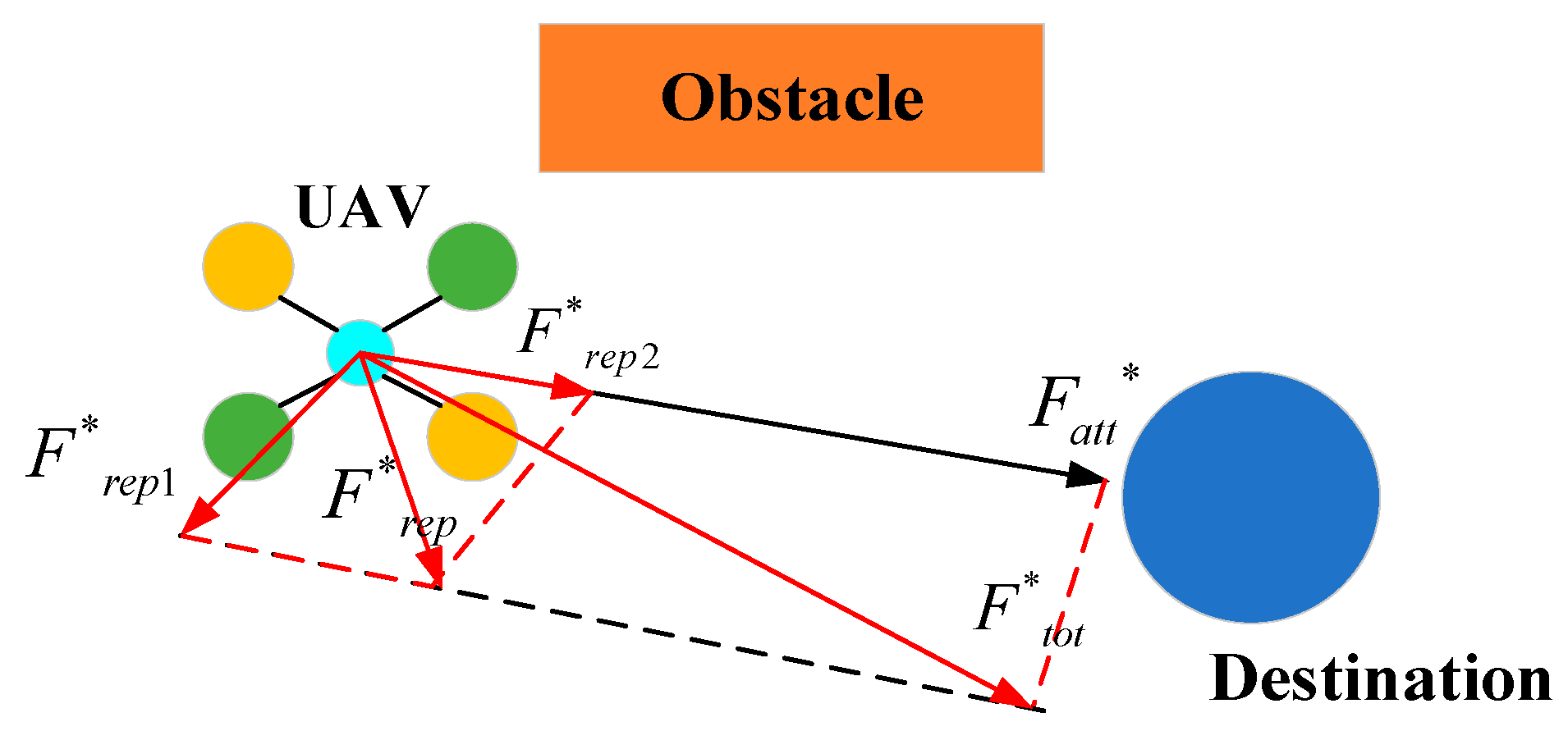
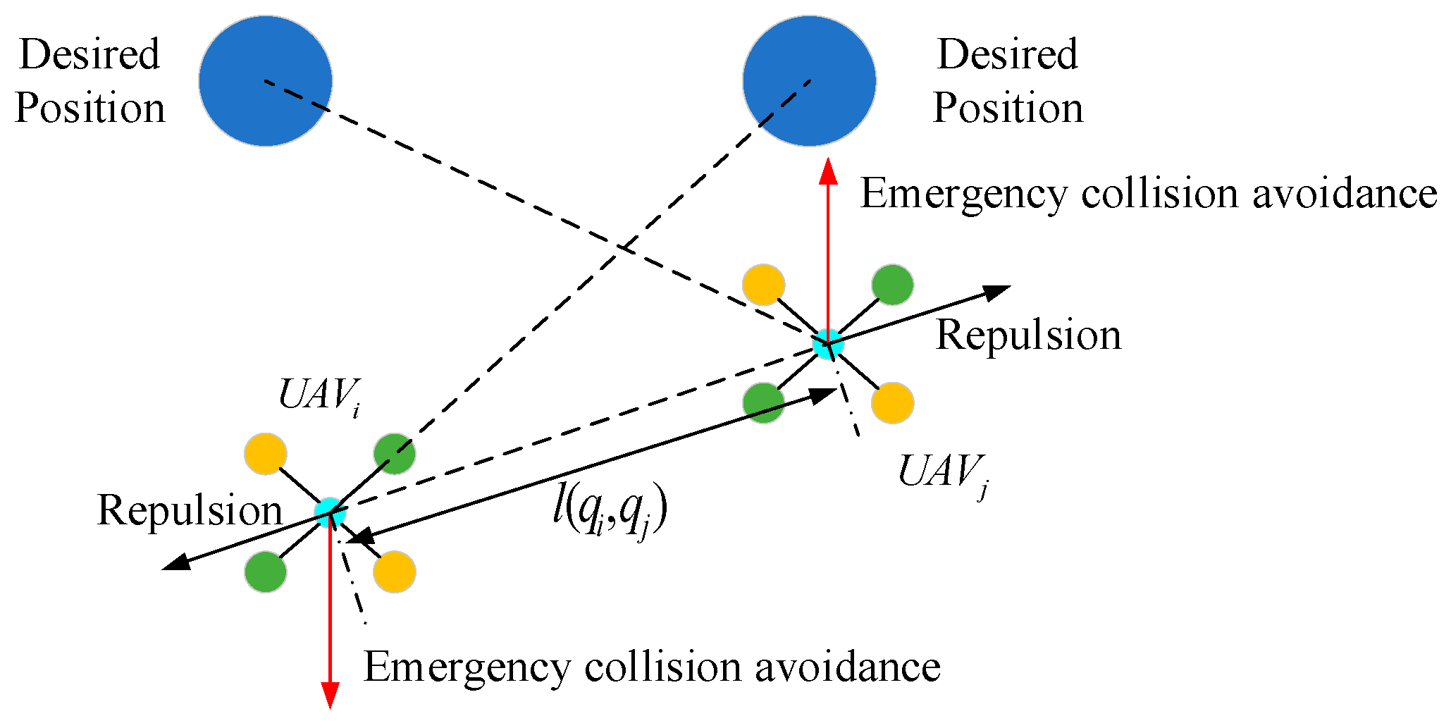
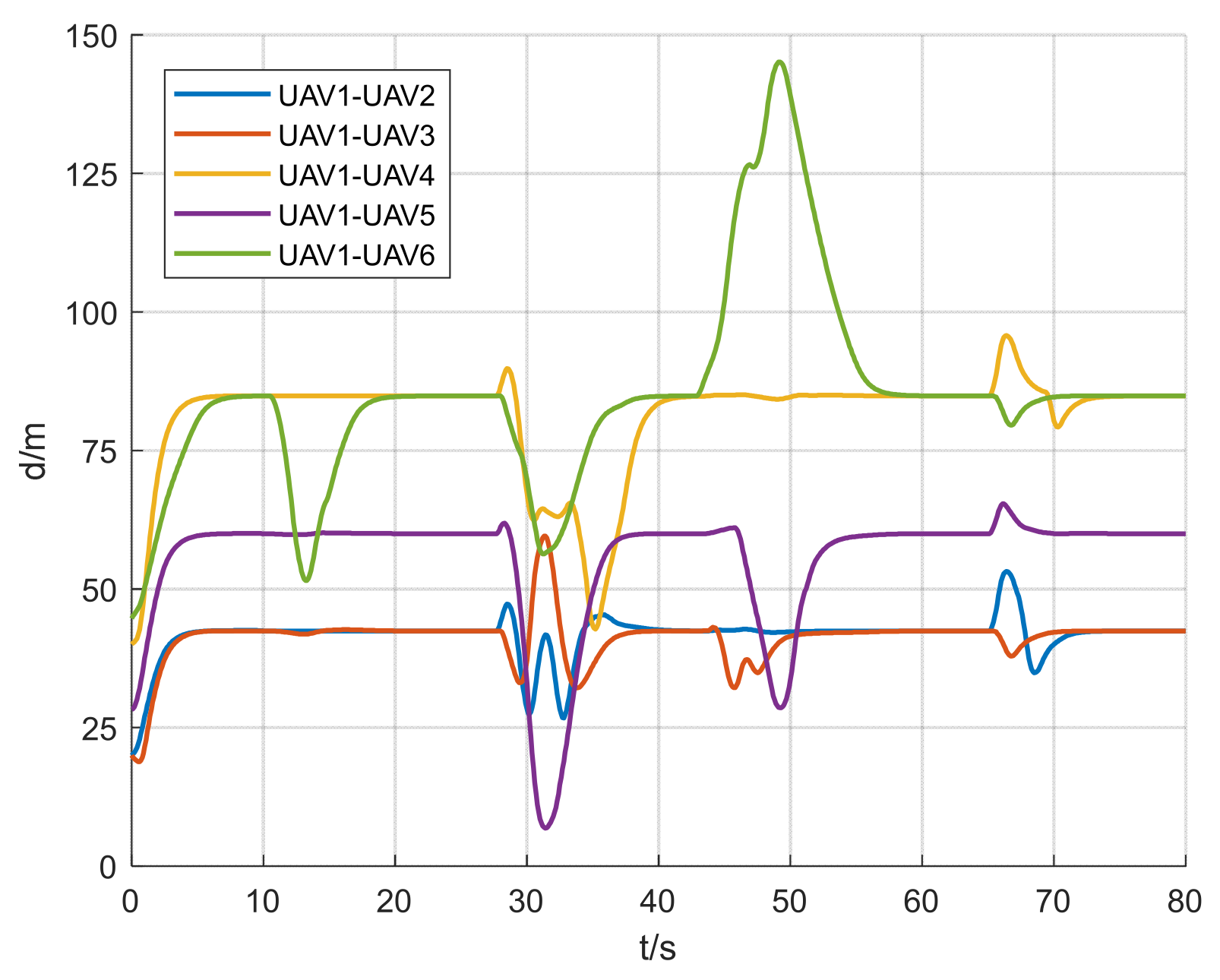
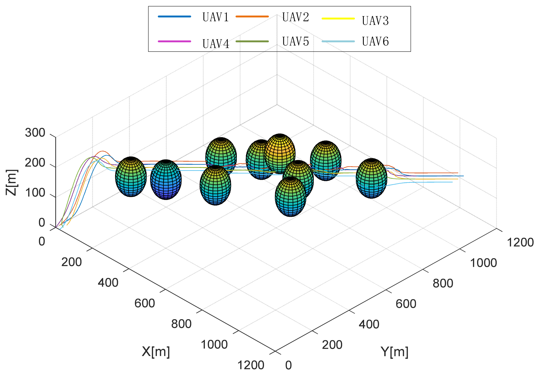
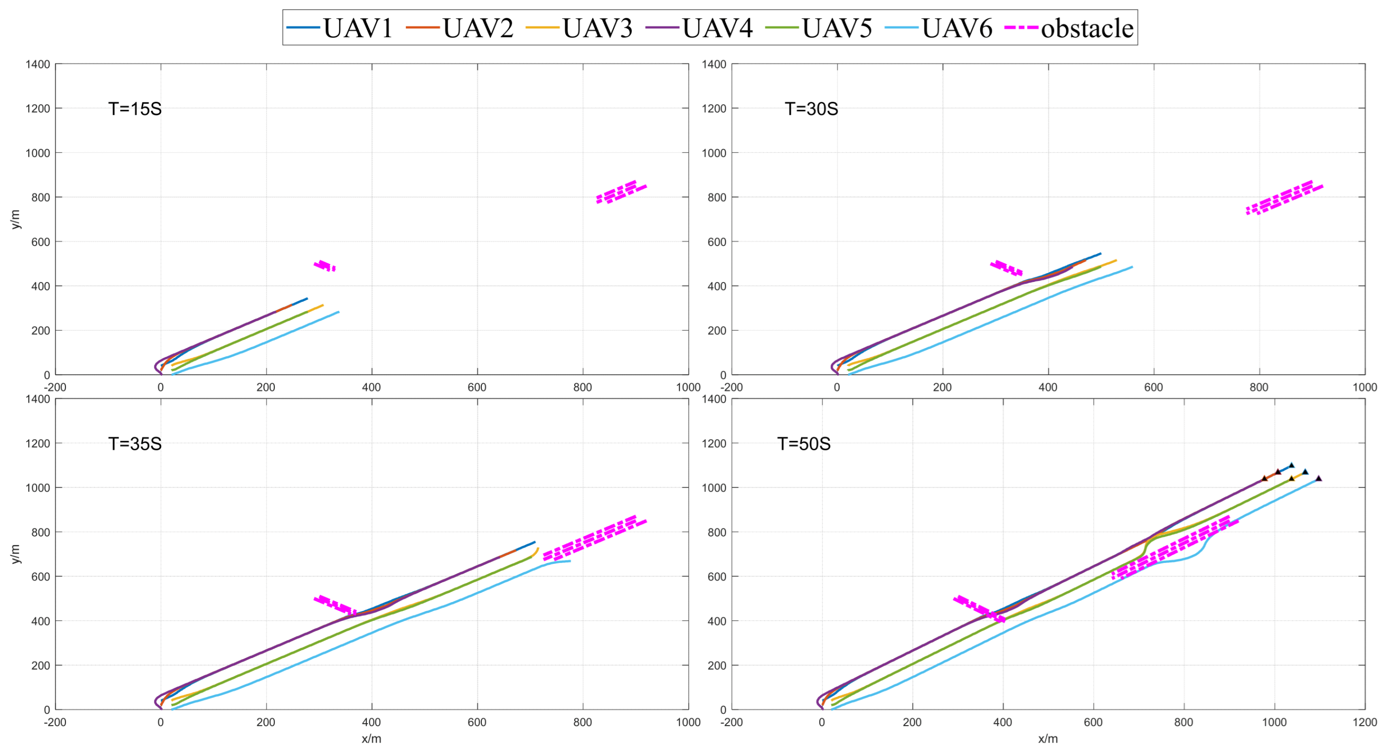
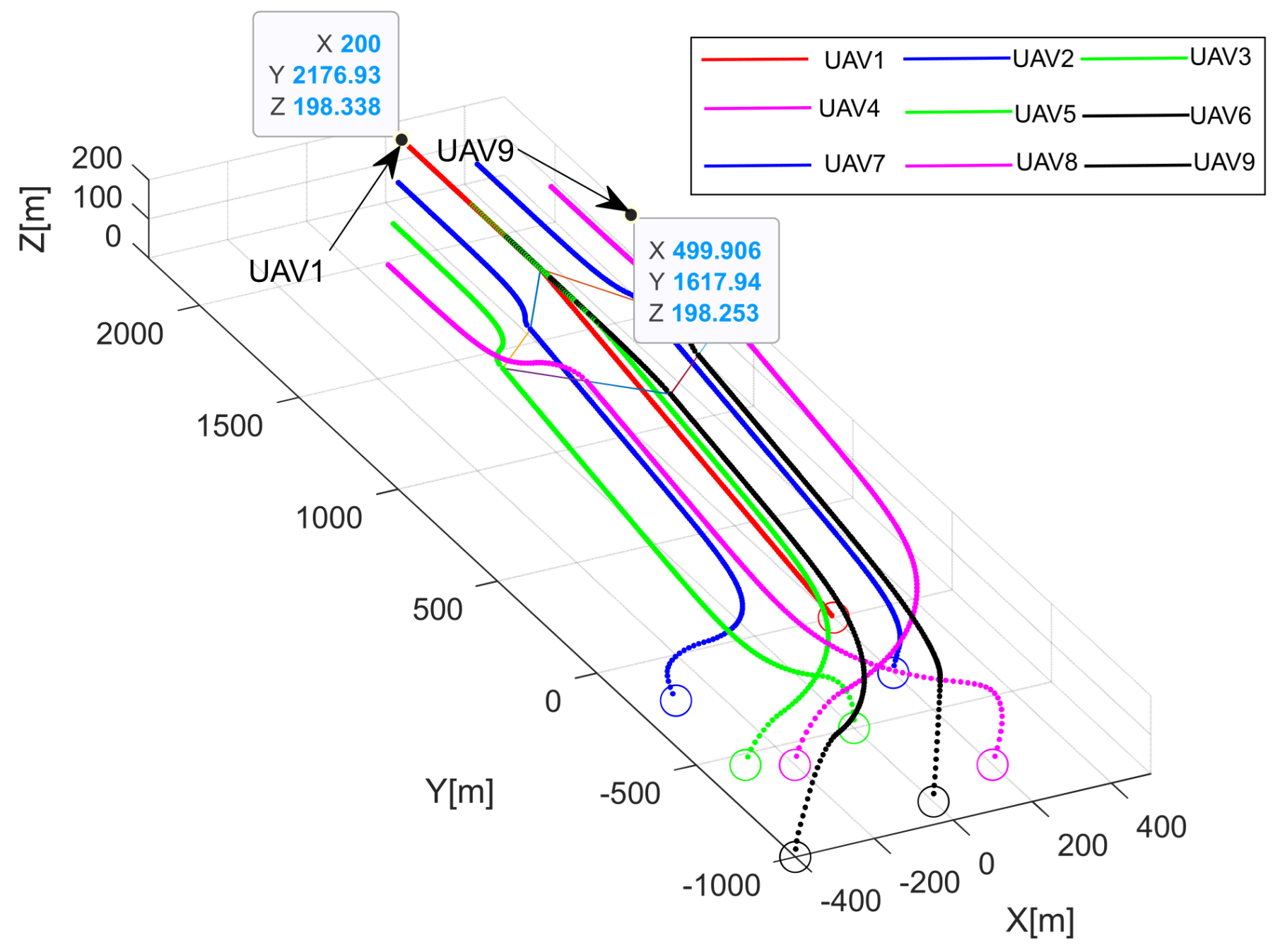
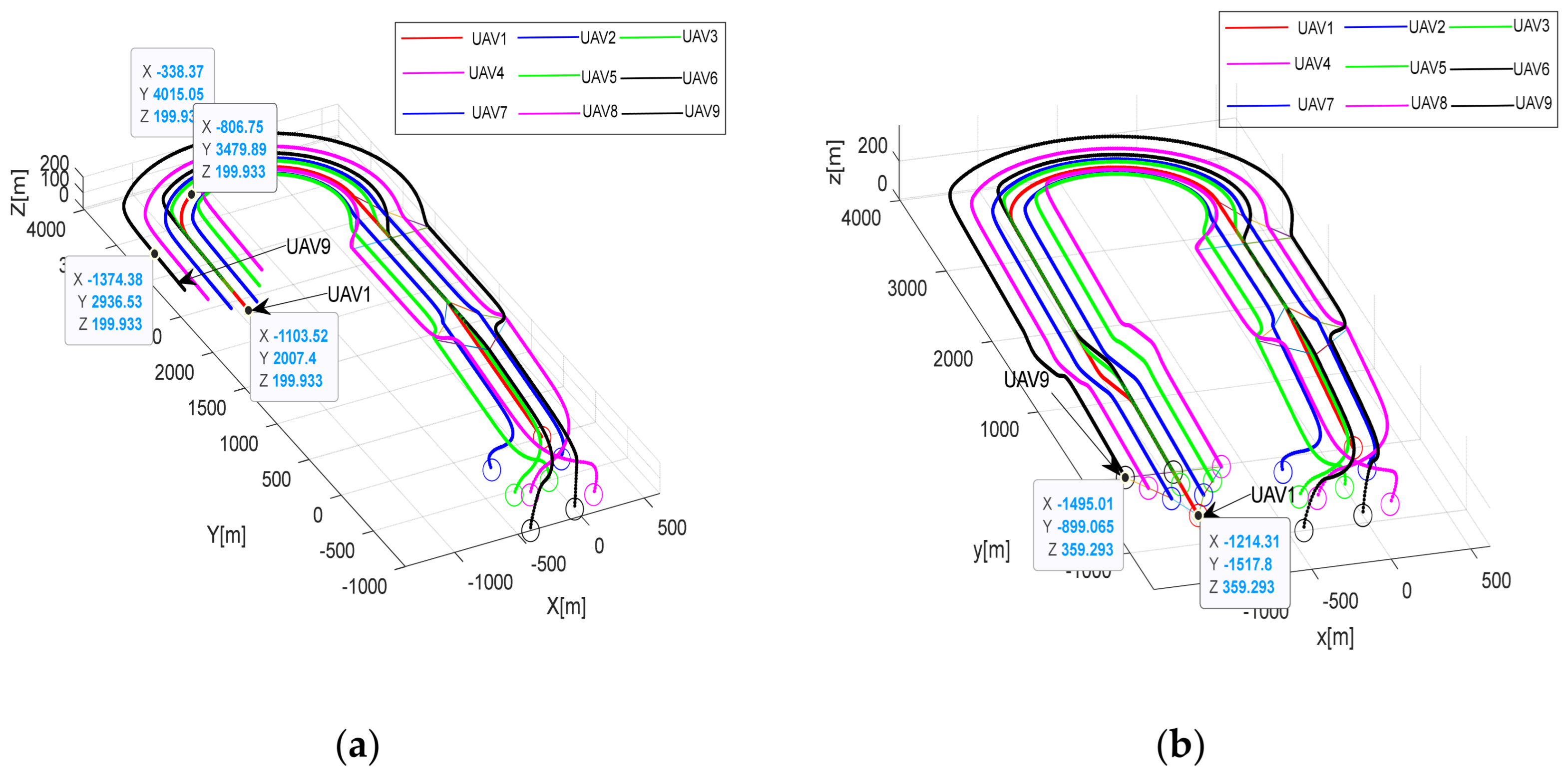
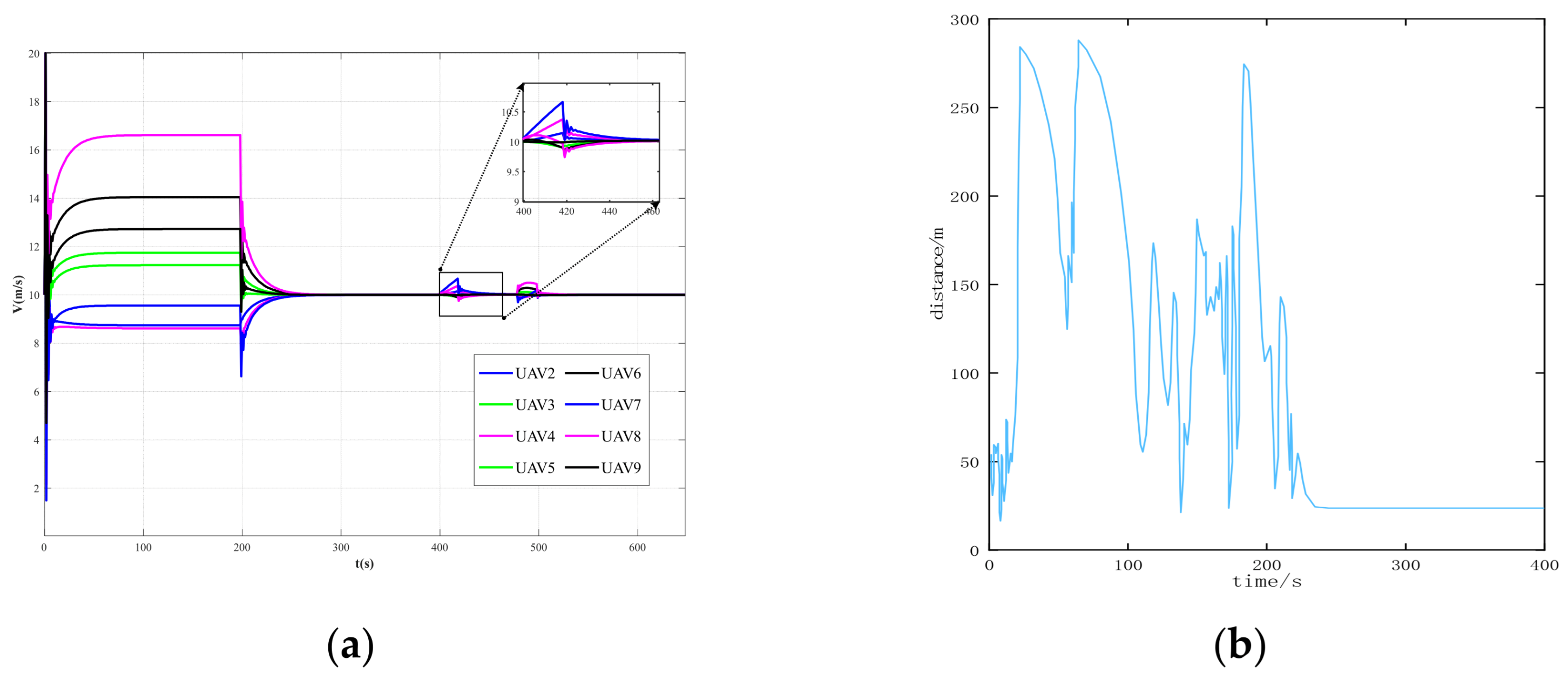
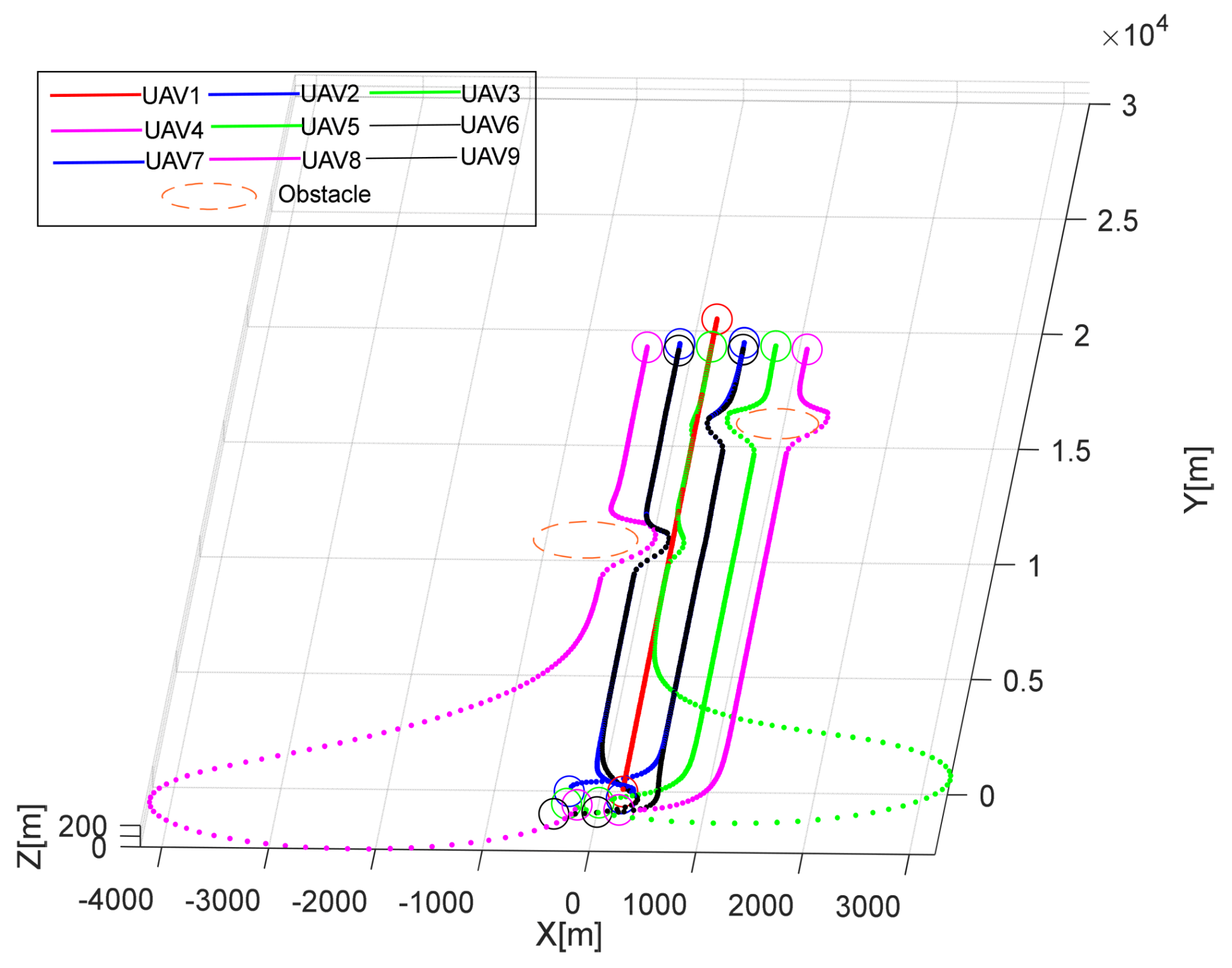
This section focuses on the design and development of the formation avoidance control system by integrating the IAAPF method with SMC. This system addresses the dynamic challenges associated with UAV formation flights in obstacle-rich environments. Specifically, the IAAPF method enhances traditional potential field approaches by introducing segmented attraction potential fields and adaptive factors, which allow for more refined control over obstacle avoidance. This is further strengthened by the integration of SMC, which is known for its robustness in dealing with system uncertainties and external disturbances. The combination of these two approaches ensures that UAV formations not only maintain stability during flight, but also effectively avoid collisions with both static and dynamic obstacles, even under challenging conditions. The design of the system plays a critical role in ensuring that UAVs can perform coordinated tasks while maintaining the integrity of their formation.
4.1. UAV Dynamics Modeling
The dynamic model of a quadrotor UAV forms the basis of establishing a UAV controller system [
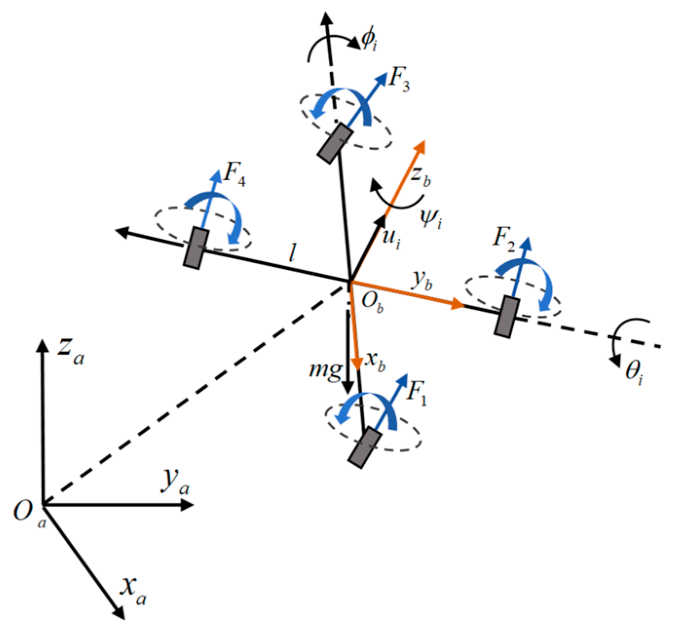
26]. In this study, the quadrotor is modeled based on several standard assumptions to facilitate the design of the control system. Firstly, the UAV is assumed to be a rigid body, meaning that it does not undergo deformation during flight. This assumption allows for the omission of structural flexibility, which is typically negligible for small UAVs. Secondly, the quadrotor is considered to have a symmetrical structure that simplifies the inertia matrix and decouples rotational motions, making them easier to control. Finally, the center of gravity is assumed to coincide with the origin of the body-fixed frame, enabling a more straightforward application of the forces and torques in the dynamic equations. These assumptions are crucial for streamlining the development of control algorithms while ensuring reliable performance in most practical scenarios. The body coordinates are denoted as
and the ground coordinates as
. Based on these, a rotational coordinate system is constructed, as shown in
Figure 3. In this study, the quadrotor has six degrees of freedom, including three positional variables
and three Euler angles
.
The dynamics of the quadrotor UAV is modeled as expressed below:
In the equations: , , , and are the control inputs of the virtual channels; , , and are the roll, pitch, and yaw angles, respectively; , , and are the moments of inertia around the x, y, and axes, respectively; m is the mass of the quadrotor body; is the radius of the quadrotor frame; and g is the gravitational acceleration.
From the quadrotor UAV dynamics model, it can be observed that the quadrotor UAV is an underdriven model with four inputs and six outputs. In order to reduce the difficulty in designing the controller, it is converted to a fully driven model by introducing virtual control quantities
,
and
. The virtual control quantities are as expressed below:
By inverting the attitude angles for
,
and
, the desired inputs to the attitude control can be solved, which in turn enables full drive control [
27]. The desired inputs for the roll angle
and pitch angle
are as expressed below:
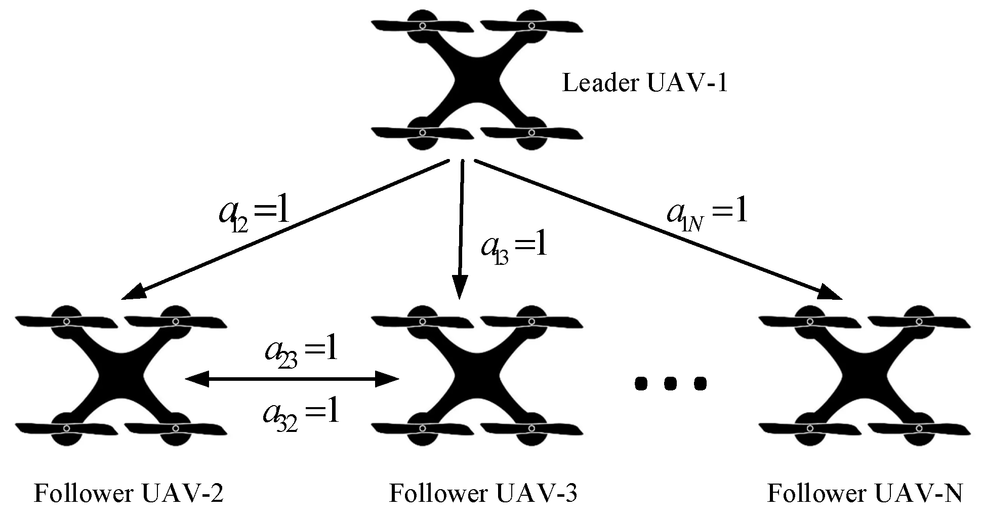
A multi-UAV formation control method is proposed to maintain a leader-follower formation, as illustrated in
Figure 4. The method integrates the techniques of attraction potential field based on a segmented strategy and repulsion potential field combined with adaptive factors, as discussed earlier, aiming to achieve obstacle avoidance and formation flight among multiple UAVs. By dynamically adjusting the parameters of the repulsion potential field, the UAVs maintain the formation while avoiding obstacles and sudden changes in paths, ensuring the stability and safety of the formation flight.
Consider a formation consisting of
I quadrotor UAVs using a leader-follower method, as denoted by
[
28,
29]. Where
L represents the leader UAV, and
N represents the number of follower UAVs. In
Figure 4, the communication topology among
N UAVs can be represented by a directed graph
, where each UAV is abstracted as a node, and the set of all nodes is denoted by
. The communication method, where a dot represents the sender and an arrow indicates the receiver, is represented by
as the directed edges, indicating that UAV
i can transmit information to UAV
, but not vice versa.
represents the set of all edges in the topology [
30]. The adjacency matrix of the graph
G is denoted by
, where
As shown in
Figure 4, UAV 1 can communicate with UAV 2, but UAV 2 cannot transmit information back to UAV 1. UAV 2 and UAV 3 can communicate with each other. UAV 3 can receive information from UAV 1 and UAV 2, but it cannot transmit its information to UAV 1. The adjacency matrix
represents the weight coefficients of the communication relations between the lead UAV and the follower UAVs.
As shown in
Figure 5, the objective of the leader-follower formation controller is to achieve the desired configuration on the
plane, which can also be at the same desired altitude
at different altitudes. The formation topology is maintained by ensuring a constant distance
d and the required angle
between each follower and the formation leader. (a) Relative Distance Components: The components
and
represent the distance in the
X and
Y directions, respectively, adjusted for the heading angle
. (b) Position Coordinates:
are the coordinates of the leader UAV, and
are the coordinates of the follower UAV. (c) Heading Angle Consideration:
is the heading angle of the leader UAV, which defines its orientation relative to the
X-axis. Thus, the equations are derived to maintain the formation structure by considering the relative positions and heading angles of the UAVs, ensuring that the follower UAV maintains the desired formation distance
d and angle
relative to that of the leader UAV.
To account for the heading angle
of the leader UAV, which defines its orientation relative to the
X-axis, a rotation transformation is performed. This transformation is necessary to maintain the formation structure by considering the relative positions and heading angles of the UAVs. The transformed coordinates are derived as follows:
where
,
represent the position differences in global coordinates.
Substitution of position differences, the equations become
where
and
represent the
and
coordinates of the actual distance
. This transformation ensures that the follower UAV maintains the desired formation distance
and angle
relative to that of the leader UAV.
Equation (28) describes the relationship between the leader and follower UAVs’ positions in the plane. Specifically, represents the heading angle of the leader UAV relative to the . The equations are derived as follows: (a) and are the components of the distance in the and directions, respectively. (b) and are the coordinates of the leader and follower UAVs; (c) is the heading angle of the leader UAV, which defines its orientation.
Thus, these equations provide the necessary components for maintaining the formation structure by considering the relative positions and heading angles of the UAVs.
4.2. Position Control of the Multi-UAV
By applying an SMC, it is possible to maintain the formation of a UAV squadron even in disturbed or uncertain environments [
31]. The formation control error must satisfy the following:
where
and
are the expected distances between the pilot and the follower in coordinates
and
, respectively.
As shown in
Figure 6, the SMC maintains the error between real-time information and expected information at zero, which is defined by the scalar equation
[
32,
33]. The SMC is utilized to minimize this error, thereby achieving formation control based on the SMC.
The second-order tracking problem can be transformed into a first-order stabilization problem; thus,
where
indicates the squared distance to the sliding surface, and
is a positive constant.
The control law is designed to ensure that the system states follow the desired trajectories. In the context of SMC, the control input is typically applied to the system to drive the state s to zero. This approach ensures that the tracking error e and its derivative are minimized.
The following equation can be used to control the formation of each follower in the formation:
In this context, represents a positive gain, and the control law is implicitly part of the dynamics, ensuring that remains zero. To clarify, the Lyapunov candidate function used in SMC ensures that the error dynamics are driven to zero, stabilizing the system. Equation (31) aligns with this principle by setting up a condition where the sliding variable and its dynamics are bounded and driven toward stability.
The position control problem is transformed into an attitude control problem, and a direct estimation of the attitude can be used to control multi-UAV formation.
where
and
are the formation control gains of
,
;
and
are the pitch and roll angles of the UAVs.
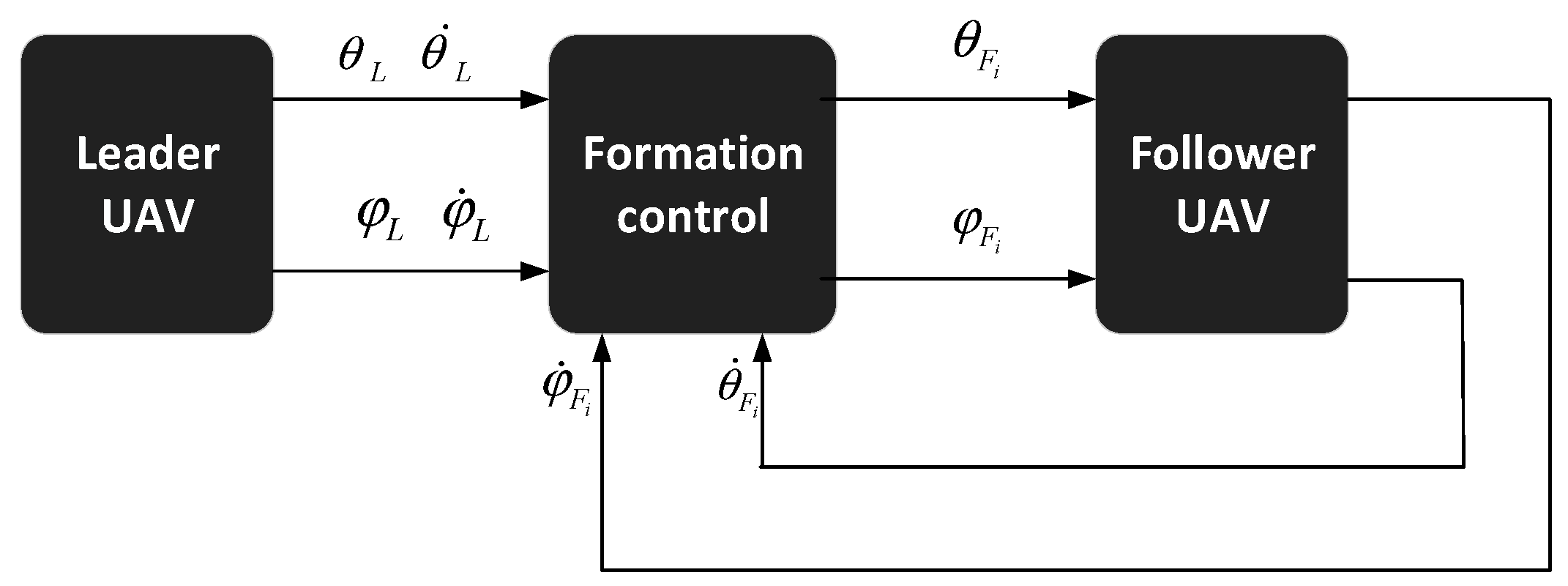
To better explain the working mechanism of this control method, as shown in
Figure 7, the system is divided into four independent channels: altitude channel,
cascade channel,
cascade channel, and yaw channel. The altitude and yaw channels are controlled directly by the virtual control quantities
and
, respectively. Finally, the position control problem is transformed into an attitude control problem, where the direct estimation of the attitude is used to control the formation [
34,
35].
- (a)
Control of altitude position
The altitude channel is used as an independent channel with SMC. Define the position error of altitude as
as expressed below:
To derive the virtual control quantity for the altitude channel in this paper, the construction method of the roll channel controller presented in reference [
36] is utilized.
where
acts as a gain or weighting factor, while
,
and
define the system parameters and tune the controller;
,
; the sliding surface
of the altitude channel is
; and
.
Bringing the virtual control quantity
into Equation (23) yields the control quantity
for the altitude channel.
To avoid the singularities in Equation (36) when the
or
approach
, a two-pronged strategy is adopted. Constraints are imposed on the pitch and roll angles to prevent them from reaching the critical values:
where
is a small margin.
When the angles approach the critical limits, the control system switches to a quaternion-based representation. This representation avoids the singularities associated with the Euler angles. The quaternion-based control law for the altitude channel is given by
where
represents the yaw angle, and the use of the quaternion ensures smooth and continuous control without singularities.
From Equation (21), the mathematical models for the
x and
y channels are similar; therefore, the
x-channel is used as an example. From Equations (21) and (22), the equation of state of the
x-channel is obtained as expressed below:
Since the mathematical model of the x-channel is a second-order system, an SMC for the x-channel needs to be designed.
First, define the tracking error
and velocity error
for the
x-channel:
The first-order derivative of the tracking error
is
To ensure stability, the first Lyapunov function is chosen as
Derivation of Equation (42):
Using
as the virtual control quantity, the desired virtual control quantity
is when:
Define the error between the virtual control quantity
and the desired virtual control quantity
as
, as expressed below:
The derivation of Equation (45) is as follows:
Based on the method used to define the sliding surface described above. Define the sliding surface as
and derive it to obtain:
A fast power-of-two convergence rate is used, the mathematical expression of which is shown below:
where
defines the system parameters and tunes the controller,
,
.
The control rate is obtained by combining Equations (47) and (48) as expressed below:
Based on the above method, the virtual control rate
for the
y-channel can be obtained as expressed below:
where
,
are constants with typical or standard values,
,
, and the sliding surface
is
.
To ensure that the designs of , and satisfy the relationship shown in Equation (22), a detailed verification process is provided. This process demonstrates that the individual designs of , and align with the overall system dynamics and control objectives.
- (a)
To clarify the relationships and equations used, the following restatements are made:
Firstly, the virtual control quantities are derived as previously shown in Equation (22).
Secondly, the designed control quantities are obtained from the previously presented Equations (36), (47) and (48).
This approach ensures that the individual designs of , and align with the overall system dynamics and control objectives, as detailed in the aforementioned equations.
- (b)
Expressing in Terms of , and
In addition, to verify consistency,
is expressed with
and
:
- (c)
Substituting Designed into and
Next, the designed
from Equation (36) is substituted into the expressions for
and
as follows:
Finally, the derived expressions for
and
are compared with their designed forms (Equations (49) and (50)) to ensure they match:
The steps taken demonstrate that the designed control quantities , and are consistent with the quadrotor UAV dynamics described as described by Equation (22). This verification ensures the validity and reliability of the control design.
Formal proof of consistency for across axes.
Ensuring the consistency of the control input across the , , and axes is crucial for the reliable operation of the UAV under the proposed control framework. This section presents a rigorous proof that the value of , derived from the control laws corresponding to each axis remains consistent under the specified control laws and system constraints.
- (a)
Derivation of from each axis: The virtual control inputs , , and are defined in terms of the primary control input as follows.
From these relationships, the control input
can be expressed for each axis as follows:
- (b)
Establishing consistency conditions: To ensure the consistency of across all axes, it is necessary that:
This equality implies the following conditions:
These conditions must hold true for the system to maintain consistent control across the , , and axes.
- (c)
Addressing angular and acceleration dependencies: The consistency of across the axes requires careful consideration of the following factors:
The trigonometric terms involving , , and are functions of the UAV’s orientation. It is essential to ensure that these terms do not introduce any inconsistencies in the derived values. This is achieved by constraining the angular parameters to avoid singularities, particularly near critical angles, such as or . These constraints prevent the denominators in the expressions for , , and from approaching zero, which could otherwise lead to significant variations in the calculated .
The system’s dynamics, particularly the accelerations
,
, and
, play a significant role in the control inputs. The control gains
,
,
,
,
,
are chosen to satisfy the following condition:
This ensures that the acceleration terms do not introduce inconsistencies between the different values derived from the x, y, and z axes. Similar conditions are applied for the y and z axes.
- (d)
Mathematical proof of negative definiteness: To further solidify the consistency of a Lyapunov function is defined, and its time derivative is derived to demonstrate system stability.
The terms in are designed such that: for all , , and corresponding accelerations. The negative definiteness of implies that the system’s error dynamics drive the system toward stability, thereby ensuring that the control input derived from any axis remains consistent.
Demonstrate the stability of the SMC using Lyapunov-Like Lemma to construct the Lyapunov function containing
and
:
The derivation of
is obtained by combining Equations (44), (45) and (48):
Construct the matrix
:
Substituting the error dynamics, given the sliding surface
and its relation to the error dynamics:
Rewriting in terms of the siding surface, substitute
into the quadratic form:
This form shows that the quadratic term involving dominates, ensuring the positive definiteness of the Lyapunov function derivative. Thus, Equation (65) holds when considering the sliding surface dynamics and error dynamics in the Lyapunov stability analysis.
If the matrix
can be guaranteed to be positive definite then:
To ensure that matrix
is positive definite, the determinant
must satisfy the following condition:
The stability proof for the backstepped SMC in the y-channel is the same as that for the x-channel.
Consider a UAV system with the control laws , and designed according to the relations provided in Equations (36), (49) and (50). Under these control laws, the UAV will avoid undesired equilibrium points in the presence of obstacles and disturbances.
To ensure the stability of the system, a Lyapunov function
is constructed. The function is given by
where
are the tracking errors in the
,
and
directions, respectively.
The time derivative of
along the trajectories of the system is
Using the control laws and system dynamics, the expressions for , , , , and are substituted.
By incorporating the control laws
,
and
into the aforementioned derivative, the following result is obtained:
To ensure that
is negative definite, the control gains must satisfy the following inequalities:
These inequalities ensure that the negative contributions from the sliding surface terms outweigh the positive contributions from the desired accelerations.
The control gains
,
,
,
,
and
should be chosen such that they are sufficiently large to account for any changes in the signs of
,
and
. Specifically, the gain terms must ensure that
This condition ensures that even if , , or change signs, the corresponding gains will still dominate, keeping negative.
Formal proof of negative definiteness:
- (a)
Assumption on acceleration terms: The desired accelerations , and are bounded by a known positive constant . This assumption is reasonable in practical scenarios, as UAVs typically operate within physical limits and their accelerations cannot grow unbounded.
This boundedness condition ensures that any potential positive contribution from the desired acceleration terms in the expression for can be counteracted by appropriately chosen control gains.
- (b)
Selection of control gains: The control gains , , , , and are selected to dominate any positive contributions from the desired accelerations. Specifically, the gains must satisfy the following conditions:
These inequalities ensure that the negative terms involving the sliding surfaces , and in the expression for outweigh any positive contribution from the desired accelerations , and .
- (c)
Substitution into the Lyapunov derivative: With the selected control gains, substitute these conditions back into the expression for derived earlier. The control gains , , , , and have been chosen such that the negative terms , and their counterparts for the and axes dominate any positive terms from the desired accelerations , and . This implies for all , , and corresponding accelerations.
Since all terms contributing to are either negative or zero, is conclusively proven to be negative definite. This result ensures that the Lyapunov function decreases over time, which is a critical indicator of system stability. The negative definiteness of implies that the UAV’s control system will naturally drive the state errors , and to zero, along with the sliding surfaces , and , thereby ensuring convergence to the desired trajectory and avoiding undesired equilibrium points.
The control gains are chosen such that is negative definite. This ensures that is always decreasing, leading to the stability of the system and convergence of the errors to zero. The terms , , and represent the desired acceleration components. The design ensures that these terms drive the system away from undesired equilibrium points by continuously updating the desired trajectories based on the obstacle feedback and state errors.
By segmenting the control system into these distinct channels, the UAV’s altitude and yaw can be managed independently, allowing for precise control through the direct input of the virtual control quantities. This approach simplifies the overall control strategy by breaking it down into manageable parts and leveraging the direct estimation of the attitude to achieve cohesive formation control.
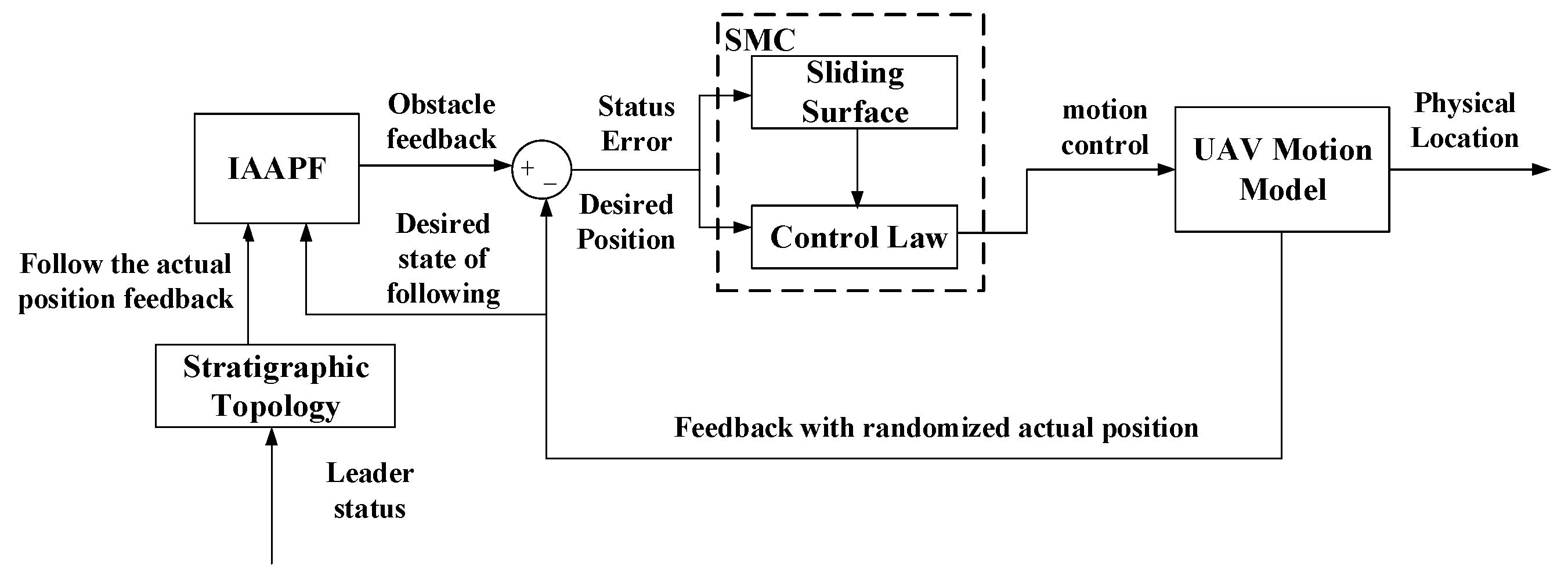
In the design of a dynamic trajectory planning method for multi-UAVs, the obstacle avoidance method, as an independent module, needs to be connected to the formation control module and primarily operates before the motion controller of the follower receives the desired state information [
37]. This paper adopts a feedback control system with inner and outer loops to connect the obstacle avoidance module based on the IAAPF (inner loop) and the SMC module based on the leader-following method (outer loop). In this design, the outer loop is responsible for generating the desired path or trajectory, while the inner loop is responsible for tracking these trajectories. The state error passed to the motion controller of the follower is no longer directly calculated from the desired state based on the leader’s state and control commands, but rather derived from the obstacle feedback obtained by the IAAPF based on the desired state of the follower and the actual states of each UAV, which is then combined with the position error of the actual state of the follower and input into the follower’s motion controller. The follower motion controller considers obstacle feedback before receiving the desired state information. This approach ensures effective obstacle avoidance while maintaining the shape of the formation, as shown in
Figure 8.
In this closed-loop control system, the key lies in the computation of the corrected desired state and corrected control commands. Here, the obstacle feedback is integrated into the desired state, and the state error is used to correct the control commands. The corrected desired state
, state error
, and corrected control commands
are as follows:
where
is the desired position state vector,
is the actual position state vector,
is the original attitude control vector,
is the obstacle feedback vector,
is the state error vector, and
is the proportional gain matrix.
The computation of the corrected desired state and corrected control commands is integral. The desired state () is modified by incorporating the obstacle feedback (), resulting in a corrected desired state (). The state error () is derived from the difference between this corrected desired state and the actual state (). The original control commands () are then adjusted based on this state error to form the corrected control commands (), ensuring that the UAV follows the desired trajectory while effectively avoiding obstacles.
