Article

Adaptive Factor Fuzzy Controller for Keeping Multi-UAV Formation While Avoiding Dynamic Obstacles

Department of Aeronautics and Astronautics, Fudan University, Shanghai 200433, China
*
Author to whom correspondence should be addressed.
Drones 2024, 8(8), 344; https://doi.org/10.3390/drones8080344
Submission received: 29 May 2024 / Revised: 21 July 2024 / Accepted: 23 July 2024 / Published: 25 July 2024

Abstract

The development of unmanned aerial vehicle (UAV) formation systems has brought significant advantages across various fields. However, formation change and obstacle avoidance control have long been fundamental challenges in formation flight research, with the majority of studies concentrating primarily on quadrotor formations. This paper introduces a novel approach, proposing a new method for designing a formation adaptive factor fuzzy controller (AFFC) and an artificial potential field (APF) method based on an enhanced repulsive potential function. These methods aim to ensure the smooth completion of fixed-wing formation flight tasks in three-dimensional (3D) dynamic environments. Compared to the traditional fuzzy controller (FC), this approach introduces a fuzzy adaptive factor and establishes fuzzy rules to address parameter-tuning uncertainties. Simultaneously, improvements to the obstacle avoidance algorithm mitigate the issue of local optimal values. Finally, multiple simulation experiments were conducted. The findings show that the suggested method outperforms the proportional–integral–derivative (PID) control and fuzzy control methods in achieving formation transformation tasks, resolving formation obstacle avoidance challenges, enabling formation reconstruction, and enhancing formation safety and robustness.

1. Introduction

Over the past few years, researchers have increasingly focused on the cooperative control of multiple unmanned aerial vehicles (UAVs) formations, driven by advancements in UAV technology and the broadening scope of application scenarios. Compared to individual UAVs, UAV formation systems offer significant advantages in coordinated reconnaissance, area search, and disaster rescue [1,2,3]. However, the complexity introduced by factors such as external obstacles and environmental uncertainties makes the cooperative control of multi-UAV formations more challenging than controlling individual unmanned aircraft [4]. In practical applications, multi-UAV formation systems must perform tasks such as formation transformation and obstacle avoidance in complex three-dimensional (3D) dynamic environments. Formation transformation enables the system to adapt to various mission requirements, thereby enhancing its adaptability and flexibility. Meanwhile, obstacle avoidance is essential to guaranteeing the system’s safe and efficient operation in dynamic environments, particularly to prevent collisions with obstacles or other vehicles during flight [5,6,7,8]. These tasks have an immediate impact on the system’s flexibility, safety, and efficiency, which raises the bar for formation control technology.
Establishing a suitable formation control model is essential for multi-UAV formation control [9,10]. The model should reflect the adaptability of the flight formation while ensuring stability and resistance to interference in the formation flight control. Existing control structures for UAV formations aim to address various practical challenges. Key methodologies include the leader–follower method [11], artificial potential field (APF) method [12], behavioral decomposition method [13], and virtual structure method [14]. Chen et al. [15] recently presented a feature modeling-based master–slave UAV formation flight control technique. This method establishes the positional relationship model between virtual slaves and leaders through trajectory tracking and positional dynamic fitting. Xu et al. [16] developed a paradigm for distributed robust tracking control in quadrotor formations. Zhang et al. [17] developed a control system for time-varying formation tracking for a quadrotor UAV using a consistency-based approach. Previous studies primarily focused on quadrotor formations in two-dimensional or static environments. However, fixed-wing UAV formation systems face unique control challenges and characteristics in complex 3D environments.
Formation transformation and collision avoidance are central topics in UAV formation flight research [6,7,8]. Given its complexity, designing a robust controller is crucial to ensuring that the UAV maintains both the desired position and a safe distance [18,19]. Research on formation transformation and obstacle avoidance control for multi-UAV formation systems has made significant strides in recent years. A unique probabilistic roadmap (PRM) navigation technique for nonlinear quadcopters was suggested by Farooq [20], created especially to deal with the difficulty of changing quadcopter formations following dynamic obstacle avoidance. Li et al. [21] examined group obstacle avoidance methods for dynamic agents of both first and second orders. They proposed an algorithm for avoiding obstacles that does not require measurements of first-order dynamic agent velocities, which is especially effective when the percentage of intelligent agents that are able to detect barrier information is fixed. Okechi Onuoha thoroughly investigated the formation maneuvering control of multi-intelligent agents with triple integral dynamics that take into account parameters for sampling data and continuous time [22]. In terms of obstacle avoidance algorithms, cooperative obstacle avoidance solutions frequently employ the APF approach. APF [23,24,25] is a commonly used technique for obstacle avoidance in UAV formation. This approach computes the combined force guiding path-planning in real-time by using repulsive and gravitational forces. However, without a well-designed potential function, the APF algorithm may lead to local optimal solutions, resulting in the UAV encountering the local minima phenomenon. Zhu et al. [26] introduced a 3D UAV collision avoidance system using a modified artificial potential field (MAPF). The MAPF technique is suggested in a coordinate system with restrictions in order to isolate the decomposed forces from the MAPF method with particular physical limitations, therefore addressing the drawbacks of the conventional APF approach.
In summary, the transition from single UAV flight to multi-UAV formation flight brings many challenges, such as maintaining formation flight in complex environments, changing formations when performing tasks, and avoiding collisions. To solve these problems, researchers began to explore the use of fuzzy control algorithms in formation control. Fuzzy control is a method based on fuzzy logic that can handle uncertainties and nonlinear problems in the system. In formation flight control, fuzzy control is used to design robust controllers that ensure UAVs are in the desired position and maintain a safe distance. Nair et al. proposed a fuzzy sliding mode control method that uses adaptive adjustment technology to control the formation flight of spacecraft [27]. This method maintains the stability of formation flight in uncertain environments through adaptive adjustment technology. Compared with traditional sliding mode control methods, this method better handles uncertainties and disturbances in the system. Ding [28] applied fuzzy logic control to achieve autonomous formation flight capabilities for small UAV systems. This method enables UAVs to autonomously change formations and avoid obstacles when performing tasks through fuzzy logic control. Compared with other formation flight control methods, this method has stronger robustness in dealing with nonlinear problems and uncertainties. Pang R. et al. proposed a multi-UAV formation maneuvering control method based on a Q-learning fuzzy controller [29]. This method enables multiple UAVs to perform efficient maneuvering control in formation flight through a Q-learning fuzzy controller. Compared with traditional maneuvering control methods, this method better handles the interaction and coordination problems between UAVs. Mobarez et al. proposed a fixed-wing UAV formation flight method based on an adaptive neuro-fuzzy inference system [30]. This method maintains the formation flight of fixed-wing UAVs in complex environments through an adaptive neuro-fuzzy inference system. Teixeira et al. proposed a quaternary fuzzy control method for UAV formation flight [31]. This method maintains the formation flight of UAVs in complex environments through fuzzy control. Tran et al. [32] proposed a distributed formation control method using a fuzzy self-adjusting strict negative imaginary consensus controller for aerial robots. Compared with reinforcement learning fuzzy control methods, this method enables aerial robots to perform effective control in formation flight through fuzzy self-adjustment. Fuzzy logic effectively handles uncertainty and nonlinear problems in systems. Yu et al. [33] introduced adaptive theory in the fuzzy control of quadcopter formations, enhancing the system’s adaptability and control accuracy. In control design, Li et al. [34] applied fuzzy logic systems to approximate nonlinear functions, considering both the system state and the state rate, and employed adaptive optimization for formation control problems.
The above research shows that the application of fuzzy control in formation flight control has made significant progress. However, the application of fuzzy control in formation flight control still faces some challenges, such as selecting the parameters of fuzzy control and dealing with the computational complexity of fuzzy control. Therefore, the application of fuzzy control in formation flight control continues to have great research value. First of all, there is the parameter selection problem of fuzzy control. Traditional fuzzy control requires significant time and effort in selecting quantization factors and scaling factors, and the parameters are not very versatile. Selecting appropriate fuzzy control parameters is essential to ensuring the stability of UAV formation flight. This requires a deep understanding of the UAV dynamic model, flight environment, and mission requirements. Secondly, there is the problem of the computational complexity of fuzzy control. Fuzzy control algorithms need to process a large number of fuzzy rules and fuzzy reasoning, which can lead to high computational complexity. However, with the development of computing technology, this problem is gradually being solved.
To address the identified challenges, this study explores the control of fixed-wing nonlinear UAV formation flight, with a focus on formation changes and obstacle avoidance. It proposes a formation adaptive factor fuzzy controller along with an enhanced APF method. To begin, we develop a model of formation space relative motion, derived from the aircraft’s six degrees of freedom (6-DOF) nonlinear framework, presented as a system of equations. Secondly, the nonlinear dynamic inversion (NDI) method is employed as an independent controller to decouple the subsystems. Subsequently, an adaptive factor is integrated into the fuzzy control system to design an adaptive formation controller, enhancing control efficiency and performance. Thirdly, we introduce a new repulsive potential function that improves the conventional APF method, thereby advancing the obstacle avoidance capabilities in formation flight. Finally, we conduct a series of simulations in the devised scenario. The results affirm the superiority of our proposed method, significantly enhancing control performance and addressing the limitations of traditional approaches. Compared to feedback linearization or backstepping, our proposed adaptive factor fuzzy control method demonstrates lower computational complexity and higher efficiency. Additionally, compared to neural network control, our method, through the introduction of fuzzy logic, can effectively handle system uncertainty and external disturbances, offering better robustness. The following is a summary of the primary contributions of our research:
  • Unlike most studies that focus on simpler quadrotor formations and 3-DOF aircraft dynamics models, this paper develops a more comprehensive formation space relative motion model using a fixed-wing single-aircraft 6-DOF model. This approach integrates the full 6-DOF dynamics of each UAV, thus providing a more accurate and realistic simulation of air maneuvering, and it improves the applicability of our approach.
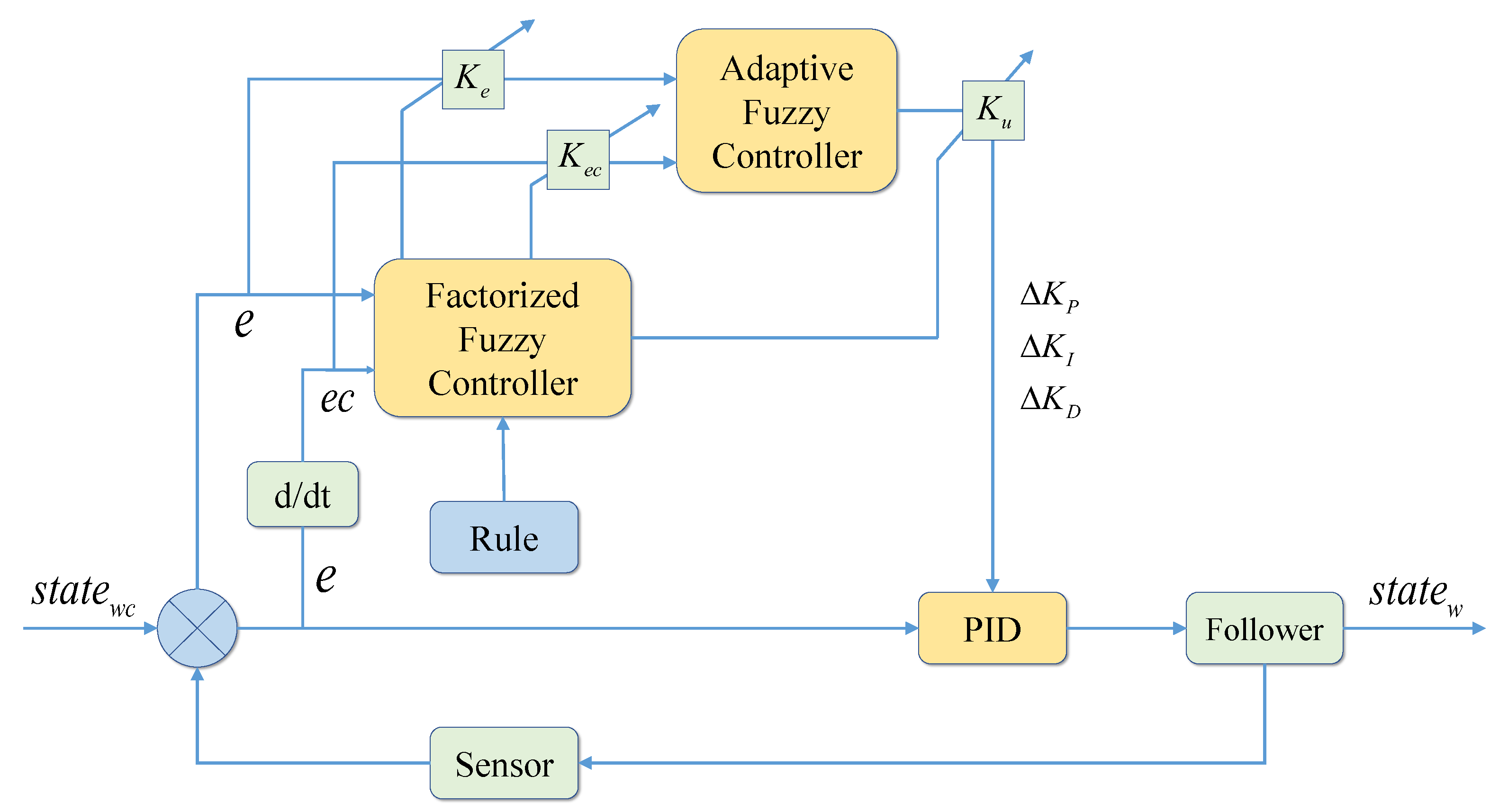
  • Since the traditional fuzzy control selects fixed values for quantization and proportionality factors, and the selection process is time-consuming and blind, the selected quantization and proportionality factors may no longer be suitable when the formation control system is subjected to large perturbations. We improve the formation fuzzy control system, which is specially designed for the complexity of 6-DOF vehicle dynamics, and cleverly construct the appropriate quantization and scaling factor forms. At the same time, we summarize the past experience of experts to establish the corresponding fuzzy rules, and use fuzzy algorithms to realize the factor adaptive adjustment, enhance the parameter generalization ability, and be able to dynamically adjust the control parameters in real-time so as to enhance the stability and adaptability of the formation system under various flight conditions. We establish quantization and proportional factor fuzzy rules to integrate the adaptive factors into the traditional fuzzy control that usually relies on static rules, which makes the traditional fuzzy controllers more adaptive, solves the problem that the quantization and proportional factors need to be selected in a time-consuming and laborious way, enhances the ability of parameter generalization, and improves the control efficiency and performance.
  • The traditional artificial APF can achieve good obstacle avoidance results in relatively simple environments with a small number of formation UAVs, but in relatively complex environments, there is the problem of local minima to the extent that the target is unreachable. We have redesigned the repulsive potential function to improve the APF method by introducing the repulsive force adjustable parameter and the decay rate dynamic adjustment parameter. As a result, the UAV can flexibly adjust its flight path according to the proximity of obstacles, which greatly improves the collision avoidance ability of the UAV in complex dynamic environments.
  • Previous research typically reduces the formation flight environment to two-dimensional planes and static obstacles. In contrast, this paper develops a more complex 3D spatial environment featuring multiple static and dynamic obstacles, presenting greater challenges to controller performance.
This paper is structured as follows: Section 2 models the spatial relative motion of a fixed-wing nonlinear UAV formation. Section 3 introduces the formation adaptive factor fuzzy controller and designs the APF method with an improved repulsive potential function. To demonstrate the effectiveness of the control mechanism, Section 4 provides simulation data along with a detailed build of the simulation environment. Section 5 summarizes the main conclusions of the paper and suggests directions for further research.

2. Formation Model

The establishment of a single aircraft model serves as the foundation for formation control. It involves creating a flight simulation system for the aircraft using mathematical models encompassing kinematics, dynamics, aerodynamics, and engine characteristics [35]. In a 3D dynamic environment, UAV formations are required to execute complex tasks involving formation changes and obstacle avoidance. The traditional linearized aircraft model is inadequate for accurately describing aircraft motion under such conditions. This study provides a body-axis nonlinear model of fixed-wing aircraft with 6-DOF [36]. The fixed-wing UAV 6-DOF nonlinear dynamic model consists of twelve state variables: velocity V, angle of attack α , sideslip angle β , roll angle velocity p, pitch angle velocity q, yaw angular velocity r, track roll angle μ , track inclination angle γ , track yaw angle χ , and the coordinates x, y, z of the center of mass projected onto the horizontal plane.
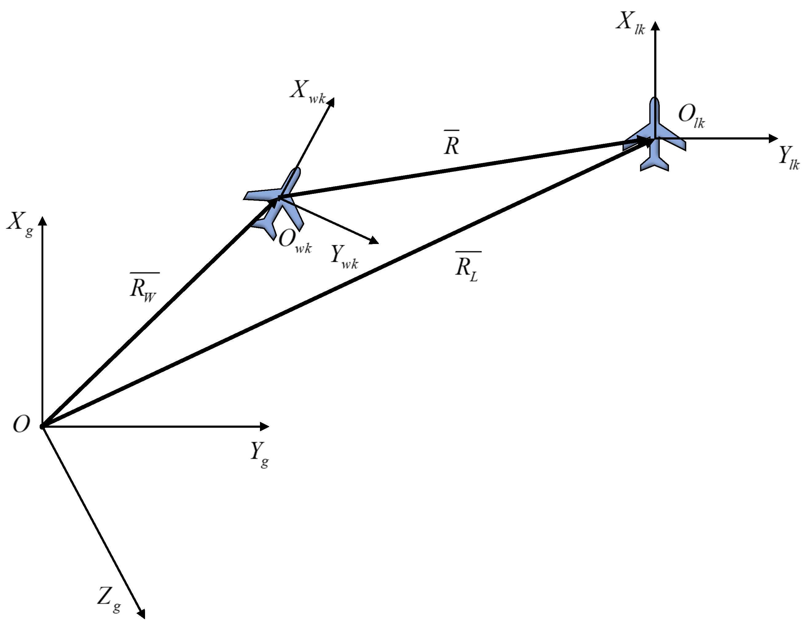
In the context of multi-UAV cooperative control, a mere amalgamation of individual UAVs cannot fully exploit its inherent benefits. Effectively processing complex tasks necessitates some form of integration [37,38]. The formation control framework in this study is established using the leader–follower approach, drawing on both the flight mission of the research subject and practical engineering expertise. Maintaining the relative distance between the leader and following UAVs is an essential component of this design. Hence, this paper develops their relative motion model in 3D space, illustrated in Figure 1, showing the connection between the leader’s and follower’s position vectors in the ground coordinate system.
The following equation can be derived from the relationships within the coordinate system, shown as
R ¯ L = R ¯ W + R ¯
Differentiating the aforementioned equation yields
d R ¯ L d t = d R ¯ W d t + d R ¯ d t + δ R ¯ δ t + ω ¯ w × R ¯
where ω ¯ w = p w q w r w T , R ¯ = x d y d z d T .
Continuing the analysis and transformation of the coordinate matrix results in the following equations
C k g = cos γ cos χ sin χ sin γ cos χ cos γ sin φ cos χ sin γ sin χ sin γ 0 cos γ
δ R ¯ δ t = d R x d t i + d R y d t j + d R z d t k = x ˙ d y ˙ d z ˙ d
d R ¯ L d t = V L cos γ L cos χ L V L cos γ L sin χ L V L sin γ L
d R ¯ w d t = V W cos u W cos φ W V W cos u W sin φ W V W sin u W
In summary, by substituting Equations (3)–(6) into Equation (2), we can derive the relationship of velocities in the ground coordinate system as depicted in the equation below
V L cos γ L cos χ L cos γ L sin χ L sin γ L = V w cos γ w cos χ w cos γ w sin χ w sin γ w + C w L x ˙ d y ˙ d z ˙ d + p w q w r w × x d y d z d
Consequently, the equation that follows can be derived
x ˙ d y ˙ d z ˙ d = p w q w r w × x d y d z d + C L w V L cos γ L cos χ L cos γ L sin χ L sin γ L V w cos γ w cos χ w cos γ w sin χ w sin γ w
The following equation can be derived based on the previously mentioned 6-DOF nonlinear equation of aircraft
p w = L w sin μ w + C w cos μ w m w V w cos γ w sin γ w q w = L w cos μ w C w sin μ w m w V w g cos γ w V w r w = L w sin μ w + C w cos μ w m w V w
Substituting Equation (9) into Equation (8) yields the equation describing the relative motion between the leader and the follower within the track coordinate system as illustrated in the equation below
x ˙ d = L w sin μ w + C w cos μ w m w V w y d L w cos μ w C w sin μ w m w V w g cos γ w V w z d V w + V L cos γ w cos γ L cos χ e + sin γ w sin γ L y ˙ d = L w sin μ w + C w cos μ w m w V w cos γ w sin γ w z d L w sin μ w + C w cos μ w m w V w x d + V L cos γ L sin χ e z ˙ d = L w cos μ w C w sin μ w m w V w g cos γ w V w x d L w sin μ w + C w cos μ w m w V w cos γ w sin γ w y d + V L sin γ w cos γ L cos χ e cos γ w sin γ L

3. Formation Change and Obstacle Avoidance Control

The performance of the formation controller and the quality of the obstacle avoidance algorithm are crucial for the success of formation changes and obstacle avoidance flights. In this section, we first develop a reliable single-UAV nonlinear controller. Then, adaptive control theory is integrated into traditional fuzzy control to design a new formation controller that meets the formation task requirements and includes an obstacle avoidance algorithm. This results in a complete formation system.

3.1. Nonlinear Dynamic Inverse Controller Design

Given that single UAV control technology forms the foundation of multi-UAV cooperative control, this paper initially delves into the design of a single UAV controller before proceeding to investigate the formation controller.
Feedback control methods constitute a fundamental approach to achieving control objectives within control system design. Feedback linearization, a nonlinear control design method, facilitates the conversion of the dynamic characteristics of nonlinear systems into those of linear systems through algebraic transformation. Moreover, the inverse system method employs the concept of a dynamic system “inverse” to explore feedback linearization design for general nonlinear control systems [39]. Specifically, “feedback linearization” involves employing dynamic compensation or nonlinear feedback to render a nonlinear system linear, thereby enabling the utilization of conventional linear control methods to achieve the system’s ultimate control objective [40].
Nonlinear dynamic inverse control offers significant advantages in formation flight, particularly as a standalone controller. Firstly, this control method adapts to changes in aircraft dynamics, including variations in aerodynamic parameters and the flight environment. Its adaptability makes it ideal for formation flights requiring high adaptivity, ensuring stable control performance across various flight states. Secondly, it improves control accuracy by decoupling the aircraft’s control channels and optimizing strategies for each. Precise control is crucial in formation flight to minimize interference between aircraft and maintain safe distances during complex maneuvers. Moreover, it simplifies controller design and shortens the commissioning phase, allowing each aircraft to autonomously and efficiently respond to formation commands and environmental changes, thereby enhancing the coordination and safety of the formation.
This paper utilizes the NDI control method to effectively regulate fixed-wing aircraft. These 12 states exhibit varying response speeds to control inputs, necessitating the division of the aircraft’s 6-DOF nonlinear dynamic equation into four subsystems based on the differing response speeds of the state variables [41]. These subsystems can be categorized by their respective time scales, according to singular perturbation theory:
(1)
Fast state: includes roll angle velocity p, pitch angle velocity q, and yaw angle velocity r.
(2)
Slow state: encompasses angle of attack α , sideslip angle β , and track roll angle μ .
(3)
Very slow state: comprises speed V, track inclination angle γ , and track yaw angle χ .
(4)
Slowest state: consists of position coordinates x, y, and z.
Following the analysis, the four distinct operational states—fast, slow, very slow, and slowest—are segregated into four dynamic subsystems: angular velocity control, attitude control, track control, and position control. These subsystems collectively form the comprehensive flight control system as illustrated in Figure 2.
In Figure 2, with an accurate dynamics model, NDI achieves precise control. In the outermost layer of the control structure is the position control system, responsible for precise trajectory tracking. The innermost layer is the angular velocity control system, which calculates the UAV rudder deflection commands based on the angular velocity inputs from the upper layer and sends them to the UAV dynamics model. This precision is due to its direct handling of the nonlinear dynamics of each UAV, allowing for swift and precise adjustments to changing flight conditions. In formation flight, each aircraft must instantly respond to positional and speed changes. The NDI controller calculates the required control inputs in real-time by solving the aircraft’s inverse dynamics, enabling quick and accurate positioning. With pre-designed control laws, the NDI controller automatically calculates optimal control commands for new formation patterns or to bypass obstacles.

3.2. Design of Formation Adaptive Factor Fuzzy Controller

3.2.1. Formation Motion Analysis

The goal of UAV formation maintenance is to keep the follower and the leader within the formation in a relatively stable state as per the specified criteria. This paper adopts a formation control strategy that involves designing the formation controller within the reference coordinate system of the formation to reduce the discrepancy between the actual and desired distances that separate the leader and follower.
Given the presence of diverse disturbances, eliminating errors becomes challenging. Hence, to maintain a steady spacing between the follower and the leader, this study considers not only positional errors but also errors in speed, track azimuth, and track inclination angle for follower control. Let x c , y c , z c denote the ideal separation between the leader and the follower in the UAV formation. Thus, the error vector can be represented as an equation, as follows:
E = e x e y e z e V e γ e χ e μ = x d x c y d y c z d z c V L V W γ L γ W χ L χ W μ L μ W
The reduction in error e x , e y , e z is the main goal of formation control. During formation flight, the leader guides the entire formation towards the target point, relinquishing the responsibility of maintaining formation to the follower’s controller, which adheres to the formation requirements. Thus, the control structure block diagram for formation flight can be depicted as illustrated in Figure 3.
From Figure 3, it is evident that in the formation flight control process, initially, the follower’s flight state output is converted from the relative motion coordinate system to the formation reference system (i.e., trajectory coordinates). The follower’s controller then combines the leader’s flight state with the required separation distance to determine the follower’s flight error. Subsequently, the formation controller computes the necessary angles of attack, thrust, and speed roll for the follower based on the error state. These calculations are then transmitted to the follower’s control system, which adjusts the engine thrust and rudder deflection angles to execute the maneuver. Meanwhile, the autopilot of the leader leads the entire formation towards the flight’s target point.
The formation controller plays a pivotal role in UAV formation flight. PID control exhibits simplicity in algorithm, robustness, ease of engineering implementation, and high reliability, making it particularly suitable for deterministic control systems with accurate mathematical models, commonly employed in process and motion control applications. Thus, considering engineering practicality, this paper integrates the design principles of PID control with its application in formation controller design, leveraging the previously established formation relative motion model to devise the multi-UAV formation’s fundamental PID controller. The control law is as follows:
α w c = K z P e z + K z I e z + K z D d e z d t + K γ P e γ + K γ I e γ + K γ D d e γ d t T w c = K x P e x + K x I e x + K x D d e x d t + K V P e V + K V I e V + K V D d e V d t μ w c = K y P e y + K y I e y + K y D d e y d t + K μ P e μ + K μ I e μ + K μ D d e μ d t

3.2.2. Stability Analysis and Proof of Convergence

The dynamics of a multi-UAV system are characterized as a multi-input, multi-output nonlinear system, with control inputs for each UAV generated by an adaptive factorial fuzzy controller and an APF method. These control inputs modify UAV state variables according to the relative positions of the UAVs and a predetermined formation shape. To demonstrate the system’s global stability and ensure stable convergence of the multi-UAV formation, this paper selects a Lyapunov function V, intimately linked to the system’s state. Taking into account the error vector of each UAV, this paper defines the Lyapunov function as
V = i { x , y , z , v , γ , μ , χ } 1 2 k P i e i 2 + 1 2 k I i e i d t 2 + 1 2 k D i d e i d t 2
Calculating the time derivative of V to assess the system’s stability yields
V ˙ = i { x , y , z , v , γ , χ , μ } k P i e i d e i d t + k I i e i d t d e i d t + k D i d e i d t d 2 e i d t 2
Using the PID controller equation, the control input u is shown below:
u = k P i e i + k I i e i d t + k D i d e i d t
Considering the control inputs, the system dynamics are expressed by the following equation:
e ˙ i = k e i + u
In Equation (16), k represents the intrinsic gain of the system.
To compute the time derivative of the Lyapunov function V, we initially apply dynamic substitution involving the controller and the system as follows:
e ˙ i = k e i + k P i e i + k I i e i d t + k D i d e i d t e ¨ i = k e ˙ i + k P i e ˙ i + k I i e i + k D i d 2 e i d t 2
Substituting Equation (17) into Equation (14) yields the equation below:
V ˙ = e i e ˙ i + k I i e i d t e ˙ i + k D i d e i d t d 2 e i d t 2 V ˙ = e i k e i + k P i e i + k I i e i d t + k D i d e i d t + k I i e i d t k e i + k P i e i + k I i e i d t + k D i d e i d t + k D i d e i d t k d e i d t + k P i d e i d t + k I i e i + k D i d 2 e i d t 2
When it is ensured that V ˙ 0 , this paper demonstrates that the deck can be ignored, establishing that k p i = k , which is the inherent gain of the torque system; k i = 0 to prevent the accumulation of energy through the circuit. Consequently, it is concluded that there is no need to be overly concerned about instability; k d i = 0 to avoid excessive reliance on sensors and instability. Thus, the following conclusion is obtained:
V ˙ = e i k e i + k e i + 0 + 0 = 0
By appropriately setting the gains k p i , k i , and k d i , it is possible to significantly enhance the system’s response time and stability without saturating the error signal e i . Such a configuration also allows the system to efficiently adapt to changes in external conditions, which in turn minimizes the influence of disturbances and maintains system performance within an optimal operational range.

3.2.3. Adaptive Factor Fuzzy Controller

In practical control scenarios, fine-tuning PID parameters for each channel to enhance system stability is time-consuming. Fuzzy control formulates fuzzy control tables based on expert experience and then employs fuzzy rule tables to determine control system output, offering potential assistance in parameter tuning when combined with PID control [42]. However, traditional fuzzy control still requires considerable effort in selecting quantization and scale factors. These factors are fixed, requiring time-consuming selection and potentially leading to suboptimal choices. Moreover, during significant external disturbances, previously suitable quantization and scale factors may become inadequate. The traditional fuzzy PID control structure lacks adaptive adjustment of its parameter factors as depicted in Figure 4.
In summary, this paper enhances traditional fuzzy PID control using fuzzy algorithms, enabling self-adjustment of quantization and scale factors. The structure of the adaptive factor fuzzy controller (AFFC) is depicted in Figure 5.
In Figure 5, compared to the traditional fuzzy PID control structure, the new control structure includes factor fuzzy controllers and fuzzy rules, allowing for adjustable quantization and proportionality factors, which makes the new controller adaptive. The performance of a basic PID controller depends on the selection of control parameters. In this study, we use MATLAB’s PID Tuner, combined with the empirical formula method, to initially parameterize the controller, successfully obtaining appropriate base PID parameters.
The fuzzy controller proposed in this paper defines two quantization factors, denoted as k e = n e and k e c = n e c , with n representing the quantization series of the input variable. Additionally, it introduces a scale factor k u = u n , where u denotes the boundary value of the fundamental discourse domain of the output, and n represents the quantization series of the output.
The relationship between error e and normalized error k e = n e is crucial in evaluating the performance of the control system, as it helps in optimizing the response characteristics. With a higher value of e, the control system’s response becomes more sensitive, reducing the error margin:
  • When k e (or k e c ) is large, adjust the system response for e in the range [ ec , ec ] , minimizing the risk of response errors.
  • When k e (or k e c ) is small, maintain a stable system response for e in the range [ ec , ec ] , reducing the likelihood of over-correction.
Given the fixed ratio k u = u n for the system’s dynamic response, it is practical to adjust k u according to the response characteristics:
  • When k u increases, the output fundamental domain expands, and the role of k u is enhanced so that the amount of control increases.
  • As k u decreases, the output fundamental domain shrinks as well, and the effect of k u diminishes so that the amount of control decreases accordingly.
Drawing from previous expertise, this paper establishes a fuzzy rule table for the required parameters as depicted in Table 1. Additionally, it refines the adjustment rule regarding the sum. The scale factor adjustment inversely correlates with the quantized factor sum, yielding the correction rules outlined in Table 2. It is possible to identify N as negative, ZE as zero, P as positive, L as large, M as medium, S as small, VL as very large, and VS as very small. The terms NL, PM, and NS indicate negative large, positive medium, and negative small, respectively.
At this stage, the design of the adaptive factorial fuzzy controller has been completed.
Additionally, this paper analyzes the capability boundaries of the controller to facilitate necessary adjustments and optimization of the control strategy in practical applications. The capability boundary of the controller is defined as the limit to which it can maintain system stability and perform tasks under specific system dynamics and environmental conditions. This includes, but is not limited to, maximum and minimum velocities and accelerations, limits of attitude control, and the ability to manage environmental complexity and dynamic obstacles. Consequently, the controller’s capability limitations are primarily categorized into operational and performance limitations:
  • In the initial stage, carefully setting the gains k P , k I , and k D enables the control system to respond rapidly and maintain stability under dynamic conditions. This configuration helps to avoid saturation.
  • The performance limitations of the controller are primarily influenced by the dynamics of the UAV and environmental factors. For instance, the controller might struggle to maintain a predetermined formation structure as the UAV reaches its maximum flight speed or when confronted with sudden strong winds.
Based on the analyses in Section 3.2.2, it is demonstrated that the introduction of adaptive factors enhances the efficiency and safety of multi-unmanned aircraft systems operations in complex environments.

3.3. Improved Artificial Potential Field Method

The APF involves establishing a virtual potential field within the UAV flight area. This method partitions the UAV flight force into two components: an attractive force directed toward the target point and a repulsive force away from obstacles. The combined force of these two components constitutes the propulsion force for UAV flight, enabling obstacle avoidance and successful navigation toward the target point. Figure 6 depicts the schematic diagram of the APF method.
In Figure 6, the goal exerts an attractive force on the UAV, while the obstacle exerts a repulsive force. The combined effect of these forces directs the UAV toward the target. The repulsive function calculates its gradient by taking the derivative of the distance, yielding the repulsion force
F r e p ( p ) = E a t t ( p )
The overall potential field function is formulated as follows:
E total ( p ) = E att ( p ) + i E r e p ( p )
The total force acting on the aircraft in space is represented as
F total ( p ) = E total = F att ( p ) + i F rep ( p )
However, the fundamental downside of the old APF method is the chance of the aircraft becoming stranded in local minima. The classic potential field method’s limitation of local minima, which might hinder the airplane from reaching the target spot, is being addressed. As such, the repulsion potential function is enhanced by this paper. As the aircraft approaches the target point, the repulsion potential function diminishes. Therefore, we have
E rep ( p ) = 1 2 k rep 1 p p obs 1 d 0 2 p p goal n e ζ p p obs , p p obs < d 0 0 , p p obs d 0
Equation (23) presents the improvement to the repulsion potential function. Here, p o b s represents the spatial position x o b s , y o b s , z o b s of the obstacle; k r e p denotes the repulsive field constant; d 0 signifies the obstacle’s influence radius; n represents an adjustable parameter; p p o b s stands for the Euclidean distance between the aircraft and the obstacle; and ζ is a dynamic adjustment parameter introduced to control the decay speed, and it is a positive number.
When p p o b s is reached, the gradient of the repulsive field function is determined to obtain the expression for the repulsive force
F r e p ( p ) = E r e p ( p ) = k r e p p p goal n e ζ p p o b s 1 p p obs 1 d 0 p p goal 2 + ζ 2 1 p p obs 1 d 0 2 + n 2 k r e p 1 p p obs 1 d 0 2 p p goal n 1 e ζ p p o b s 0
We define the two forces as
F 1 = k rep p p goal n e ζ p p o x s 1 p p obs 1 d 0 p p goal 2 + ζ 2 1 p p obs 1 d 0 2
F 2 = n 2 k rep 1 p p o b s 1 d 0 2 p p goal n 1 e ζ p p o b s
Along the line that connects the obstacle to the UAV, the obstacle exerts a repulsive force on the UAV. On the other hand, a gravitational pull is applied to the drone by the target point along the path that connects the drone and the target. Equations (25) and (26) will now be examined and analyzed.
(1)
If 0 < n < 1 , ζ > 0 , we have
lim p p goal 0 F 1 = lim p p goal 0 k rep p p goal n e ζ p p obs 1 p p obs 1 d 0 p p goal 2 + ζ 2 1 p p obs 1 d 0 2 = 0
lim p p goal 0 F 2 = lim p p goal 0 n 2 k r e p 1 p p obs 1 d 0 2 p p goal n 1 e ζ p p o b s =
The gravitational pull of the target point tends towards infinity, while the repulsive force of the obstacle on the aircraft decreases towards zero as it approaches the target point. Consequently, the aircraft moves towards the target point influenced by both the gravitational force and another force represented by F att .
(2)
If n = 1 , ζ > 0 , we have
lim p p goal 0 F 1 = lim p p goal 0 k rep p p goal n e ζ p p o b s 1 p p obs 1 d 0 p p goal 2 + ζ 2 1 p p obs 1 d 0 2 = 0
lim p p goal 0 F 2 = lim p p goal 0 n 2 k r e p 1 p p obs 1 d 0 2 p p goal n 1 e ζ p p o b s = 1 2 k rep 1 p p obs 1 d 0 2 e ζ p p o b s
The gravitational force acting from the target point stays constant as the aircraft gets closer to it, while the repulsive force of the obstacle on it decreases towards zero. The aircraft moves towards the target point under the combined influence of the gravitational force and another force represented by F att .
(3)
If n > 1 , ζ > 0 , we have
lim p p goal 0 F 1 = lim p p goal 0 k rep p p goal n e ζ p p obs 1 p p obs 1 d 0 p p goal 2 + ζ 2 1 p p obs 1 d 0 2 = 0
lim p p goal 0 F 2 = lim p p goal n 2 k rep 1 p p obs 1 d 0 2 p p goal n 1 e ζ p p obs = 0
The gravitational force F 2 from the target location and the repulsive force F 1 applied by the obstacle both decrease towards zero as the aircraft gets closer to it. The aircraft then moves towards the target point under the influence of F att .
Upon analyzing Equations (23)–(32), it is evident that the enhanced repulsion potential function includes an additional term p p goal n compared to the traditional one. This addition aims to minimize the potential field value of the aircraft upon reaching the target point during flight. Additionally, the term e ζ p p o b s is introduced to regulate weight, which diminishes rapidly as the distance from the aircraft increases, controlled by the positive parameter ζ . This helps reduce the influence of the repulsive force field with distance, preventing excessive aircraft direction adjustments at far distances. Consequently, leveraging this improved repulsive potential function resolves the issue of aircraft failing to reach the target point in the conventional APF method.

4. Simulation Verification

In this section, a complete 6-DOF nonlinear aircraft dynamics model is used as the research object. The formation controller and obstacle avoidance algorithm designed in Section 3 are applied in experimental simulations to demonstrate the effectiveness and superiority of the proposed formation control method. First, a multi-UAV formation dynamic flight simulation scene is constructed, with pre-set information such as formation configurations and obstacles. Next, the control effects of traditional PID and fuzzy PID controllers are compared. Finally, the results of formation changes and obstacle avoidance flights are described and analyzed in detail.

4.1. Simulation Environment

The research object of this paper is a fixed-wing 6-DOF nonlinear UAV model, and it is usually possible to use a mature aircraft model as a test object for control algorithms to ensure the accuracy and validity of the simulation results. In this paper, we use an F15 aircraft to validate our control strategy, and the model meets the conditions required to develop and test new control algorithms for UAVs, and the data used for the standalone modeling simulation are obtained from the JSBsim database [43].
Before starting the simulation, the F15 airplane model must be leveled. In this study, we configure the flight altitude at 3000 m and the speed at 200 m per second to maintain constant straight-line flight, and utilize Matlab’s leveling toolbox to obtain the aircraft’s leveling state quantity data: V = 200 m / s , α = 0.0239 rad , β = 0 , p = q = r = 0 , ϕ = 0 , θ = 0.0239 rad , ψ = 0 . The control inputs include δ a = 0 , δ e = 0.0133 rad , δ r = 0 , δ p = 0.3766 . Consequently, in this study, the initial states of all five airplanes in the formation are configured based on the leveling data.
To validate the performance of formation transformation and obstacle avoidance in a 3D dynamic environment, this study constructs a complex scenario comprising two static obstacles, one dynamic obstacle, and five UAVs. The formation structure adopted here is leader–follower, comprising one leader and four followers. Table 3 displays the initial state of each UAV. Relative locations in the formation between the followers and the leader in 3D space are detailed in Table 4, while Table 5 presents obstacle information during simulation.
In Table 3, the formation consists of one leader and four followers. The initial state of the formation is vertically aligned, with a 500 m front-to-back separation and no relative distance in the lateral direction. All UAVs are flying at an initial speed of 200 m/s.
The transformed formation alignments are shown in Table 4. Compared to the previous formation, the relative distance between the followers and the leader changes in both the x and y directions, resulting in a wedge-shaped formation.
As indicated in Table 3 and Table 4, this paper presets the initial and target formations by establishing the relative distances between UAVs. Once the formation receives the command to start the transformation—at the 50 s mark in the simulation—each UAV begins its formation transformation maneuver.
Table 5 provides the characteristic information of two static obstacles and one dynamic obstacle, including their original positions, heights, threat radii, safety distances, and movement speeds.
In Table 6, K att represents the gravitational field constant, K rep the repulsive field constant, d 01 the radius of influence of static obstacles, d 02 the radius of influence of dynamic obstacles, n the adjustable parameter for repulsive force, and ζ the dynamic adjustment parameter for the attenuation rate.
The formation adaptive factor fuzzy controller, integrated with the enhanced APF method, is employed to simulate obstacle-avoidance flight. MATLABR2021b software serves as the platform to build the whole formation and obstacle environment simulation model in Simulink, utilizing the ODE4 (Runge–Kutta) solver with a fixed step size of 0.01 s. The simulation terminates upon the achievement of the target direction by the leading UAV.

4.2. Simulation Results and Analysis

This section provides a detailed description and analysis of the simulation results. Figure 7 shows the flight trajectory of each UAV in the five-aircraft formation as they avoid obstacles in 3D space. Figure 8 shows the obstacle avoidance trajectory of the formation on the overhead plane, providing an intuitive display of the obstacle avoidance effect. As seen in Figure 7 and Figure 8, when the formation encounters two static obstacles during flight, each aircraft successfully avoids them. Before contacting the obstacle, the wedge-shaped formation begins to disperse. Each aircraft performs different maneuvers based on its distance from the obstacle. The entire process proceeds smoothly under the control of the formation controller.
In Figure 8, the two red circles represent two static obstacles, and the flight trajectories of the formation are depicted with curves in five different colors. It is clear that each UAV in the formation successfully avoids the obstacles. The closer the obstacles are, the more repulsive force the UAVs experience, and all UAVs return to the original formation after completing obstacle avoidance.
The four subfigures in Figure 9 respectively represent the four states before and after the formation comes into contact with the dynamic obstacle. As can be seen from the figure, the red dotted line represents the movement trajectory of the dynamic obstacle. From the flight trajectory of each aircraft, it is evident that when the formation approaches the dynamic obstacle, each aircraft maneuvers to varying degrees based on its distance from the obstacle, allowing for safe avoidance. After bypassing the obstacle, the carrier-based aircraft also execute maneuvers to avoid re-approaching it. Subsequently, the aircraft rejoin the formation under the guidance of the formation controller. The experimental results demonstrate that the formation fuzzy adaptive factor controller, combined with the improved APF method, enables the carrier-based aircraft formation to effectively avoid both static and dynamic obstacles.
Figure 10 comprises five subfigures, each depicting the evolution of the flight state quantities for the five UAVs within the formation. Based on the single-aircraft flight characteristics within the formation, this paper details the results for four critical state quantities out of twelve for the primary aircraft. The four state quantities include flight speed V, roll angle ϕ , pitch angle θ , and yaw angle ψ . The accuracy of the controller’s commands is verified by monitoring changes in these parameters throughout the simulation. Each UAV successfully performs maneuvers during formation changes and obstacle avoidance, remaining within the aircraft’s performance limits. By analyzing these parameters, we evaluate the control efficiency and capability of the standalone controller under dynamic conditions and corroborate the effectiveness of the commands generated by the formation controller. It reveals alterations in speed and the three attitude angles during static and dynamic obstacle avoidance maneuvers. These changes occur due to the rolling, yawing, and pitching movements of the UAV during obstacle avoidance. Nonetheless, the stability of the state parameters of each UAV during these maneuvers indicates effective controller performance.
Figure 11 and Figure 12 depict how four followers track a leader to maintain formation control under the guidance of three different formation controllers. According to the Figure 11, each follower begins a formation change at simulation time 50 s, subsequently navigating around two static and one dynamic obstacle. The figure’s peaks and valleys indicate that the UAVs execute large-radius maneuvers to navigate obstacles while in a high-speed flight state, thereby confirming the reliability and advancement of the enhanced obstacle avoidance algorithms. The comparison reveals that the AFFC achieves shorter regulation and steady-state times than the PID controller and FC, while minimizing steady-state error. This paper compares the response performance of three formation controllers during formation changes using the follower as a case study, with the results presented in Table 7.
Figure 12 illustrates that the relative position error variations of Follower 2 in both the x and y directions converge to zero under the influence of all three formation controllers. Notably, the AFFC exhibits superior performance compared to PID and FC, with a shorter rise time and a smaller steady-state error.
Table 7 presents the controller performance response parameters and comparison cases. It is evident from Table 7 that the rise time, regulation time, and steady-state error of the AFFC are significantly lower than those of the PID controller and FC.
Figure 13 depicts the evolution of relative distance maintenance errors for each follower controlled by the AFFC. The figure illustrates that during formation maintenance, each follower precisely follows in the direction of the anticipated formation distance, with relative distance maintenance errors nearly approaching 0. This outcome effectively confirms the formation controller’s dependability, ensuring consistent formation integrity pre- and post-obstacle avoidance. Additionally, Figure 13 shows that the vertical channel has a small relative distance maintenance error during obstacle avoidance, demonstrating that the formation maneuvers in multiple directions to avoid obstacles, including forward, backward, left, right, and vertical movements. This ensures that each drone in the formation can flexibly avoid all possible obstacles. This also confirms that the path calculated by the obstacle avoidance algorithm in this study considers all possible directions in 3D space, including vertical changes, leading to errors in the vertical channel. When the formation is in stable flight, errors in all channels are nearly zero.
Figure 14 illustrates the evolution of the distances between each UAV and two static obstacles, as well as one dynamic obstacle in space. It also presents the minimum distance values of each UAV from obstacles in the plane. This study employs the Euclidean calculation method to determine the minimum distances between UAVs, and between UAVs and obstacles in 3D space as outlined in Table 8 and Table 9.
Table 8 clearly shows the minimum spacing distance between UAVs throughout the flight. The minimum separation distance between UAVs is greater than the safe distance from obstacles.
Table 9 presents the minimum distance between the UAVs and the obstacles. The specific data comparison indicates that the minimum distance between the UAVs meets the requirements for formation flight conditions.
The findings indicate that all drones maintain a minimum distance from other drones and obstacles, ensuring safety. This highlights the superior collision avoidance performance of the adaptive fuzzy controller and the method of generating potential fields with an improved potential function for repulsive forces. These advancements offer a novel solution and technical foundation for implementing multi-UAV formation systems in complex environments.

5. Conclusions

In this paper, we design a formation adaptive factor fuzzy controller, distinct from traditional fuzzy control systems that rely on static rules. This method integrates adaptive factors to dynamically adjust control parameters based on real-time flight data, thereby enhancing UAV responsiveness to environmental changes and dynamic obstacles. Additionally, we develop an improved APF method, wherein a new repulsive potential function flexibly adjusts based on the aircraft’s proximity to obstacles, significantly enhancing the collision avoidance capabilities of UAVs in dynamic environments. Additionally, this paper integrates multi-UAV formations with 6-DOF modeling, incorporating the full 6-DOF dynamics of each UAV. This approach offers a more accurate and realistic simulation of aerial maneuvers compared to conventional 3-DOF models. Therefore, this study develops a fixed-wing aircraft simulation model and a formation control framework using nonlinear dynamic inverse control, constructs a complex 3D environment with static and dynamic obstacles, and assesses the performance of PID, fuzzy, and adaptive factorial fuzzy controllers during formation flight.
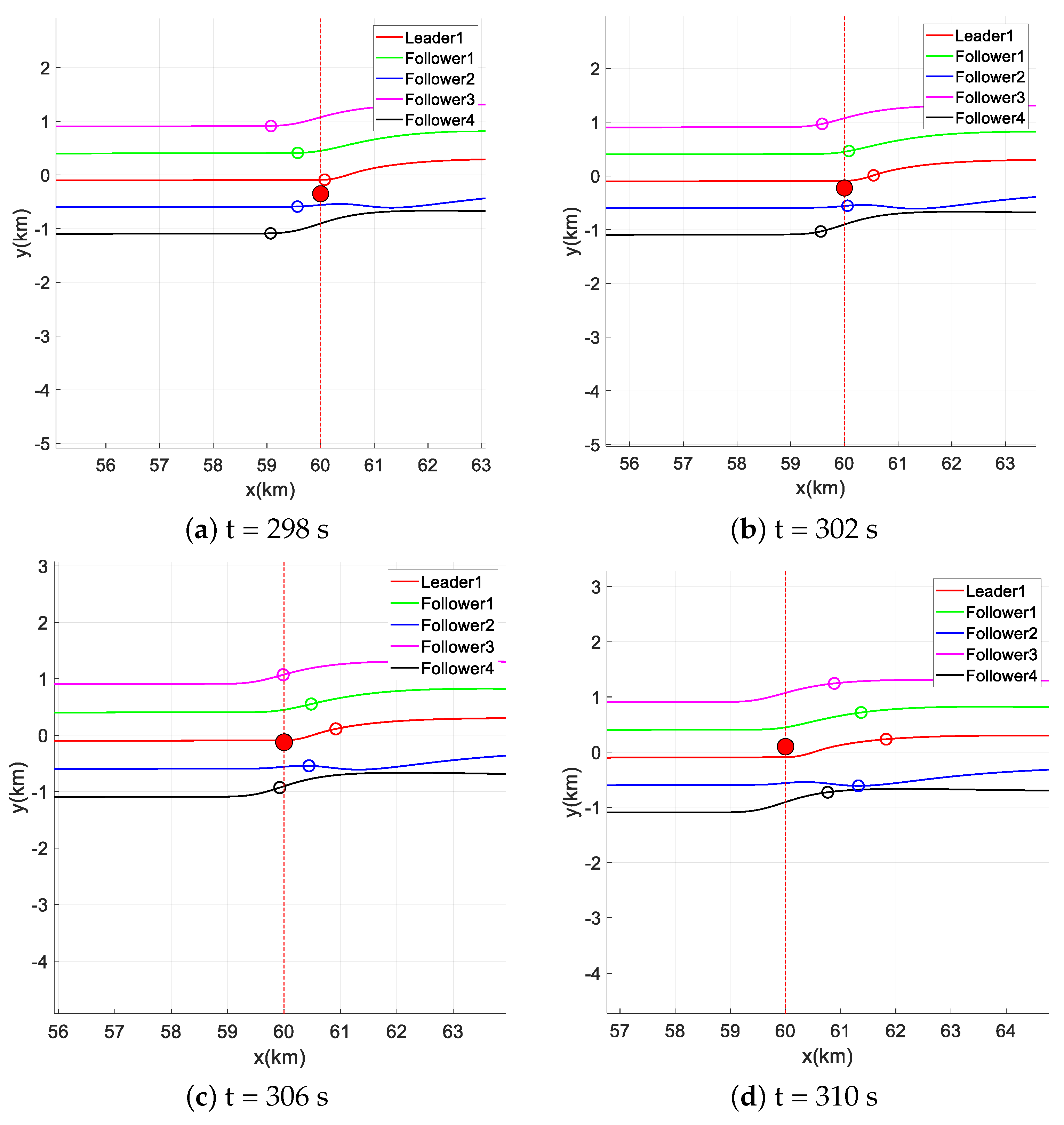
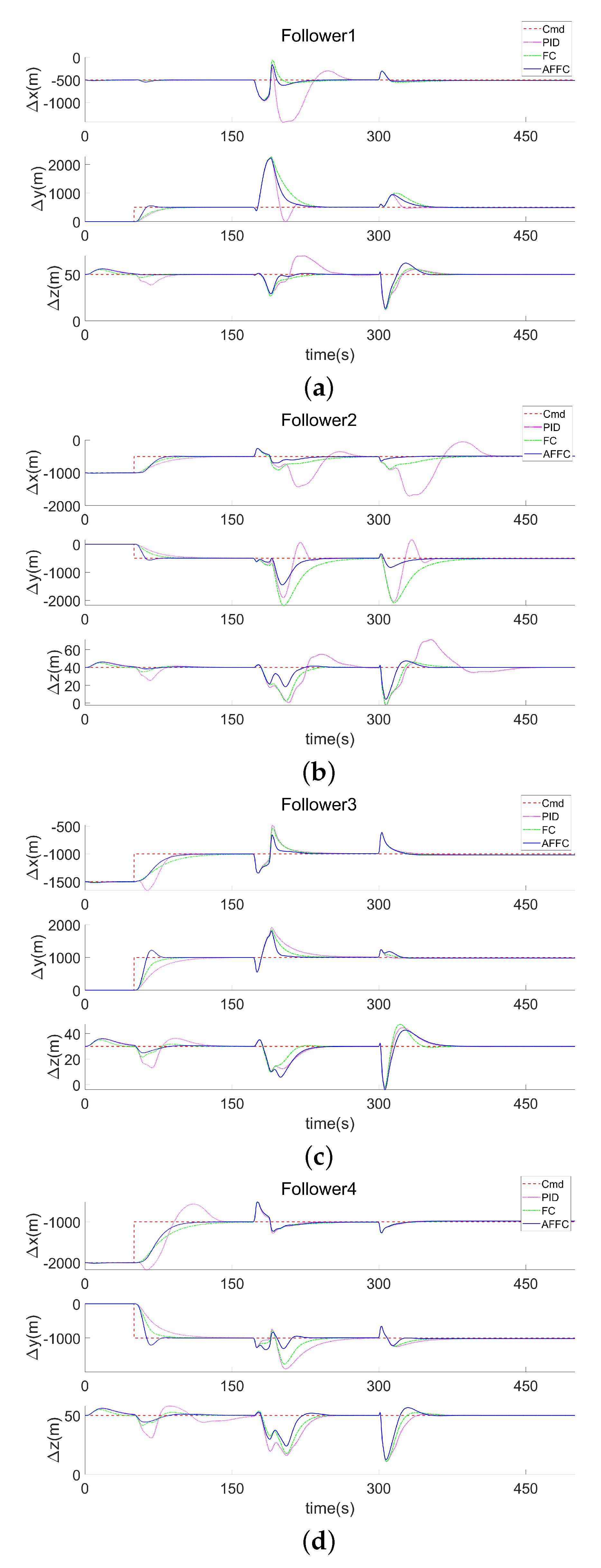
In the simulation scenario described above, the traditional PID control and fuzzy control methods struggle to adapt to the complex formation flight environment due to fixed control parameters and a complex selection process. To address these issues, a multi-channel adaptive factor fuzzy controller for followers is designed, and the APF method is incorporated to enhance the repulsive force potential function, preventing the aircraft from becoming stuck in local minima.The outcomes of the simulation show that multi-UAV formations can effectively perform formation transformations and obstacle-avoidance flights in a 3D dynamic environment, showcasing good aircraft flight performance and strong formation robustness.
Future research will explore the heterogeneous case of formation UAVs, which may include formations comprising multiple classes of aircraft with varying performance characteristics. In addition, the existing formation flight control system will be tested and improved in more complex flight environments, including the effects of aerodynamic perturbations in close-range formation flight, the effects of control input noise, and the challenges of sudden threatening obstacles in the air, in order to improve the adaptability and robustness of the formation controller. Detailed simulations of the improved APF method are also necessary to ascertain its operational limits.

Author Contributions

All authors contributed to the conceptualization and design of the research. Conceptualization, B.G. and J.A.; methodology, B.G. and Y.L.; software, B.G.; validation, B.G., Y.L. and L.Z.; formal analysis, B.G.; investigation, B.G.; resources, J.A.; data curation, B.G.; writing—original draft preparation, B.G.; writing—review and editing, B.G. and J.A.; visualization, B.G.; supervision, J.A.; project administration, J.A. All authors have read and agreed to the published version of the manuscript.

Funding

This research received no external funding.

Institutional Review Board Statement

Not applicable.

Informed Consent Statement

Not applicable.

Data Availability Statement

Data are contained within the article.

Conflicts of Interest

The authors declare no conflicts of interest.

Abbreviations

The following abbreviations are used in this manuscript:
UAVsUnmanned aerial vehicles
UAVUnmanned aerial vehicle
NDINonlinear dynamic inversion
FCFuzzy controller
PIDProportional–integral–derivative
AFFCAdaptive factorial fuzzy controller
APFArtificial potential field
MAPFModified artificial potential field
ODEOrdinary differential equation
3DThree dimensional
6-DOFSix degrees of freedom
3-DOFThree degrees of freedom
PRMProbabilistic roadmap

References

  1. Xu, T.; Liu, J.; Zhang, Z.; Chen, G.; Cui, D.; Li, H. Distributed MPC for Trajectory Tracking and Formation Control of Multi-UAVs With Leader-Follower Structure. IEEE Access 2023, 11, 128762–128773. [Google Scholar] [CrossRef]
  2. Hu, C.; Zhang, Z.; Yang, N.; Shin, H.S.; Tsourdos, A. Fuzzy multiobjective cooperative surveillance of multiple UAVs based on distributed predictive control for unknown ground moving target in urban environment. Aerosp. Sci. Technol. 2019, 84, 329–338. [Google Scholar] [CrossRef]
  3. Yang, Y.; Xiong, X.; Yan, Y. UAV formation trajectory planning algorithms: A review. Drones 2023, 7, 62. [Google Scholar] [CrossRef]
  4. Fei, S.; Xian, B.; Wang, L. Distributed formation control for multiple unmanned aerial vehicles with dynamic obstacle avoidance based on the flocking behavior. Control Theory Appl. 2022, 39, 1–11. [Google Scholar]
  5. Wang, X.; Cheng, M.; Zhang, S.; Gong, H. Multi-UAV Cooperative Obstacle Avoidance of 3D Vector Field Histogram Plus and Dynamic Window Approach. Drones 2023, 7, 504. [Google Scholar] [CrossRef]
  6. Xu, J.; Andrew Ning, S.; Bower, G.; Kroo, I. Aircraft route optimization for formation flight. J. Aircr. 2014, 51, 490–501. [Google Scholar] [CrossRef]
  7. Brodecki, M.; Subbarao, K. Autonomous formation flight control system using in-flight sweet-spot estimation. J. Guid. Control Dyn. 2015, 38, 1083–1096. [Google Scholar] [CrossRef]
  8. Seo, J.; Kim, Y.; Kim, S.; Tsourdos, A. Consensus-based reconfigurable controller design for unmanned aerial vehicle formation flight. Proc. Inst. Mech. Eng. G J. Aerosp. Eng. 2012, 226, 817–829. [Google Scholar] [CrossRef]
  9. Ali, Z.A.; Zhangang, H. Multi-unmanned aerial vehicle swarm formation control using hybrid strategy. Trans. Inst. Meas. Control 2021, 43, 2689–2701. [Google Scholar] [CrossRef]
  10. Fu, X.; Pan, J.; Wang, H.; Gao, X. A formation maintenance and reconstruction method of UAV swarm based on distributed control. Aerosp. Sci. Technol. 2020, 104, 105981. [Google Scholar] [CrossRef]
  11. Lin, Z.; Ding, W.; Yan, G.; Yu, C.; Giua, A. Leader–follower formation via complex Laplacian. Automatica 2013, 49, 1900–1906. [Google Scholar] [CrossRef]
  12. Pan, Z.; Zhang, C.; Xia, Y.; Xiong, H.; Shao, X. An improved artificial potential field method for path planning and formation control of the multi-UAV systems. IEEE Trans. Circuits Syst. II Express Br. 2021, 69, 1129–1133. [Google Scholar] [CrossRef]
  13. Lee, G.; Chwa, D. Decentralized behavior-based formation control of multiple robots considering obstacle avoidance. Intell. Serv. Robot. 2018, 11, 127–138. [Google Scholar] [CrossRef]
  14. Zhou, D.; Wang, Z.; Schwager, M. Agile coordination and assistive collision avoidance for quadrotor swarms using virtual structures. IEEE Trans. Robot. 2018, 34, 916–923. [Google Scholar] [CrossRef]
  15. Chen, Y.; Deng, T. Leader-Follower UAV formation flight control based on feature modelling. Syst. Sci. Control Eng. 2023, 11, 2268153. [Google Scholar] [CrossRef]
  16. Xu, L.; Li, Y. Distributed Robust Formation Tracking Control for Quadrotor UAVs with Unknown Parameters and Uncertain Disturbances. Aerospace 2023, 10, 845. [Google Scholar] [CrossRef]
  17. Dong, X.; Yu, B.; Shi, Z.; Zhong, Y. Time-varying formation control for unmanned aerial vehicles: Theories and applications. IEEE Trans. Control Syst. Technol. 2014, 23, 340–348. [Google Scholar] [CrossRef]
  18. Jasim, O.A.; Veres, S.M. A robust controller for multi rotor UAVs. Aerosp. Sci. Technol. 2020, 105, 106010. [Google Scholar] [CrossRef]
  19. Kazim, M.; Azar, A.T.; Koubaa, A.; Zaidi, A. Disturbance-rejection-based optimized robust adaptive controllers for UAVs. IEEE Syst. J. 2021, 15, 3097–3108. [Google Scholar] [CrossRef]
  20. Farooq, M.U.; Ziyang, Z.; Ejaz, M. Quadrotor uavs flying formation reconfiguration with collision avoidance using probabilistic roadmap algorithm. In Proceedings of the 2017 International Conference on Computer Systems, Electronics and Control (ICCSEC), Dalian, China, 25–27 December 2017; IEEE: Piscataway, NJ, USA, 2017; pp. 866–870. [Google Scholar]
  21. Li, J.; Zhang, W.; Su, H.; Yang, Y.; Zhou, H. Coordinated obstacle avoidance with reduced interaction. Neurocomputing 2014, 139, 233–245. [Google Scholar] [CrossRef]
  22. Onuoha, O.; Tnunay, H.; Ding, Z. Affine formation maneuver control of multi-agent systems with triple-integrator dynamics. In Proceedings of the 2019 American Control Conference (ACC), Philadelphia, PA, USA, 10–12 July 2019; IEEE: Piscataway, NJ, USA, 2019; pp. 5334–5339. [Google Scholar]
  23. Li, Y.; Tian, B.; Yang, Y.; Li, C. Path planning of robot based on artificial potential field method. In Proceedings of the 2022 IEEE 6th Information Technology and Mechatronics Engineering Conference (ITOEC), Chongqing, China, 4–6 March 2022; IEEE: Piscataway, NJ, USA, 2022; Volume 6, pp. 91–94. [Google Scholar]
  24. Liang, Q.; Zhou, H.; Xiong, W.; Zhou, L. Improved artificial potential field method for UAV path planning. In Proceedings of the 2022 14th International Conference on Measuring Technology and Mechatronics Automation (ICMTMA), Changsha, China, 15–16 January 2022; IEEE: Piscataway, NJ, USA, 2022; pp. 657–660. [Google Scholar]
  25. Zhang, S.; Xu, M.; Wang, X. Research on obstacle avoidance algorithm of multi-uav consistent formation based on improved dynamic window approach. In Proceedings of the 2022 IEEE Asia-Pacific Conference on Image Processing, Electronics and Computers (IPEC), Dalian, China, 14–16 April 2022; IEEE: Piscataway, NJ, USA, 2022; pp. 991–996. [Google Scholar]
  26. Zhu, L.; Cheng, X.; Yuan, F.G. A 3D collision avoidance strategy for UAV with physical constraints. Measurement 2016, 77, 40–49. [Google Scholar] [CrossRef]
  27. Nair, R.R.; Behera, L. Tracking control of spacecraft formation flying using fuzzy sliding mode control with adaptive tuning technique. In Proceedings of the 2013 IEEE International Conference on Fuzzy Systems (FUZZ-IEEE), Hyderabad, India, 7–10 July 2013; IEEE: Piscataway, NJ, USA, 2013; pp. 1–8. [Google Scholar]
  28. Ding, Y.R.; Chen, Y.H.; Sun, C.H.; Hsiao, F.B. The implementation of autonomous formation flight capability to a small unmanned aerial vehicle system based on fuzzy logic control. J. Aeronaut. Astronaut. Aviat. A 2011, 43, 301–312. [Google Scholar]
  29. Rui, P. Multi-UAV formation maneuvering control based on Q-learning fuzzy controller. In Proceedings of the 2010 2nd International Conference on Advanced Computer Control, Shenyang, China, 27–29 March 2010; IEEE: Piscataway, NJ, USA, 2010; Volume 4, pp. 252–257. [Google Scholar]
  30. Mobarez, E.N.; Sarhan, A.; Ashry, M.M. Formation Flight of Fixed Wing UAV Based on Adaptive Neuro Fuzzy Inference System. In Proceedings of the 2019 Ninth International Conference on Intelligent Computing and Information Systems (ICICIS), Cairo, Egypt, 8–10 December 2019; IEEE: Piscataway, NJ, USA, 2019; pp. 356–361. [Google Scholar]
  31. Teixeira, M.A.S.; Neves-Jr, F.; Koubâa, A.; De Arruda, L.V.R.; De Oliveira, A.S. A quadral-fuzzy control approach to flight formation by a fleet of unmanned aerial vehicles. IEEE Access 2020, 8, 64366–64381. [Google Scholar] [CrossRef]
  32. Tran, V.P.; Santoso, F.; Garratt, M.A.; Petersen, I.R. Distributed formation control using fuzzy self-tuning of strictly negative imaginary consensus controllers in aerial robotics. IEEE/ASME Trans. Mechatron. 2020, 26, 2306–2315. [Google Scholar] [CrossRef]
  33. Yu, Y.; Guo, J.; Chadli, M.; Xiang, Z. Distributed adaptive fuzzy formation control of uncertain multiple unmanned aerial vehicles with actuator faults and switching topologies. IEEE Trans. Fuzzy Syst. 2022, 31, 919–929. [Google Scholar] [CrossRef]
  34. Li, Y.; Zhang, J.; Tong, S. Fuzzy adaptive optimized leader-following formation control for second-order stochastic multiagent systems. IEEE Trans. Ind. Inform. 2021, 18, 6026–6037. [Google Scholar] [CrossRef]
  35. Dong, L.; Zhou, X.; Zhao, F.; He, S.; Lu, Z.; Feng, J. Key technologies for modeling and simulation of airframe digital twin. Acta Aeronaut. Astronaut. Sin 2021, 42, 023981. [Google Scholar]
  36. Lemon, K.; Steck, J.; Hinson, B.; Rokhsaz, K.; Nguyen, N. Application of a six degree of freedom adaptive controller to a general aviation aircraft. In Proceedings of the AIAA Guidance, Navigation, and Control Conference, Portland, OR, USA, 8–11 August 2011; p. 6562. [Google Scholar]
  37. Wang, X.; Cao, Y.; Ding, M.; Wang, X.; Yu, W.; Guo, B. Research Progress in Modeling and Evaluation of Cooperative Operation System-of-systems for Manned-unmanned Aerial Vehicles. IEEE Aerosp. Electron. Syst. Mag. 2023. [Google Scholar] [CrossRef]
  38. Kada, B.; Khalid, M.; Shaikh, M.S. Distributed cooperative control of autonomous multi-agent UAV systems using smooth control. J. Syst. Eng. Electron. 2020, 31, 1297–1307. [Google Scholar] [CrossRef]
  39. Lungu, M. Backstepping and dynamic inversion combined controller for auto-landing of fixed wing UAVs. Aerosp. Sci. Technol. 2020, 96, 105526. [Google Scholar] [CrossRef]
  40. Sahnehsaraei, M.A.; Mahmoodabadi, M.J. Approximate feedback linearization based optimal robust control for an inverted pendulum system with time-varying uncertainties. Int. J. Dyn. Control 2021, 9, 160–172. [Google Scholar] [CrossRef]
  41. Li, Y.; Cheng, L.; Yuan, J.; Ai, J.; Dong, Y. Neural Network and Dynamic Inversion Based Adaptive Control for a HALE-UAV against Icing Effects. Drones 2023, 7, 273. [Google Scholar] [CrossRef]
  42. Leal, I.S.; Abeykoon, C.; Perera, Y.S. Design, simulation, analysis and optimization of PID and fuzzy based control systems for a quadcopter. Electronics 2021, 10, 2218. [Google Scholar] [CrossRef]
  43. Cereceda, O.; Rolland, L.; O’Young, S. Giant Big Stik R/C UAV Computer Model Development in JSBSim for Sense and Avoid Applications. Drones 2019, 3, 48. [Google Scholar] [CrossRef]
Figure 1. Position vector relationship between leader and follower.
Drones 08 00344 g001
Figure 2. Structure of dynamic inverse control.
Drones 08 00344 g002
Figure 3. Structure of formation flight control.
Drones 08 00344 g003
Figure 4. Structure of traditional fuzzy control.
Drones 08 00344 g004
Figure 5. Structure of adaptive factorial fuzzy control.
Drones 08 00344 g005
Figure 6. Illustration of the APF principle.
Drones 08 00344 g006
Figure 7. The 3D flight trajectory for formation obstacle avoidance.
Drones 08 00344 g007
Figure 8. Horizontal plane trajectories for formation static obstacle avoidance.
Drones 08 00344 g008
Figure 9. Formation dynamic obstacle avoidance time history.
Drones 08 00344 g009
Figure 10. Speed and Euler angle time histories.
Drones 08 00344 g010
Figure 11. Relative positional tracking of followers.
Drones 08 00344 g011
Figure 12. Relative position error dynamics for Follower 2.
Drones 08 00344 g012
Figure 13. Relative position error dynamics for followers. (a): Relative Position Error Dynamics of Followers in the x Direction. (b): Relative Position Error Dynamics of Followers in the y Direction. (c): Relative Position Error Dynamics of Followers in the z Direction.
Drones 08 00344 g013
Figure 14. Dynamics of distance from UAVs to the obstacles.
Drones 08 00344 g014
Table 1. Fuzzy rule table for PID controller parameters.
Δ K P / Δ K I / Δ K D ec NLNMNSZEPSPMPL
e
NLPL/NL/PSPL/NL/NSPM/NM/NLPM/NM/NLPS/NS/NLZE/ZE/NMZE/ZE/PS
NMPL/NL/PSPL/NL/PSPM/NM/NLPS/NS/NMPS/NS/NMZE/ZE/NSNS/ZE/ZE
NSPM/NL/ZEPM/NM/NSPM/NS/NMPS/NS/NMZE/ZE/NSNS/PS/NSNS/PS/ZE
ZEPM/NM/ZEPM/NM/NSPS/NS/NSZE/ZE/NSNS/PS/NSNM/PM/NSNM/PM/ZE
PSPS/NM/ZEPS/NS/ZEZE/ZE/ZENS/PS/ZENS/PS/ZENM/PL/ZENM/PL/ZE
PMPS/ZE/PLZE/ZE/PSNS/PS/PSNM/PM/PSNM/PM/PSNM/PL/PSNL/PL/PL
PLZE/ZE/PLZE/ZE/PMNM/PS/PMNM/PM/PSNM/PM/PSNL/PL/PSNL/PL/PL
Table 2. Fuzzy rule table for k e and k e c .
ec  NL NM NS ZE PS PM PL
e
NLVSSMSMMSSVS
NMSMSMMMMSMS
NSMSMMMLMMMS
ZEMMLVLLMM
PSMSMMMLMMMS
PMSMSMMMMSS
PLVSSMSMMSSVS
Table 3. Initial states.
ParameterLocation (m)Speed (m/s)Yaw Angle ( rad )Velocity Roll Angle ( rad )Track Inclination Angle ( rad )Track Azimuth ( rad )
Leader 1(0, 0, 3000 )2000000
Follower 1( 500 , 0, 2950 )2000000
Follower 2( 1000 , 0, 2960 )2000000
Follower 3( 1500 , 0, 2970 )2000000
Follower 4( 2000 , 0, 2950 )2000000
Table 4. Relative locations in formation.
Parameter Δ x (m) Δ y (m) Δ z (m)
Leader 1000
Follower 1 500 5000
Follower 2 500 500 0
Follower 3 1000 10000
Follower 4 1000 1000 0
Table 5. Obstacle characteristics for multi-UAV obstacle avoidance.
ParameterOrigin Position (m)Height (m)Threat Radius (m)Safe Distance (m)Speed (m/s)
Obstacle #1(35,000, 250, 0)4000200300
Obstacle #2(38,000, 1000 , 0)4500200300
Obstacle #3(60,000, 15,400 , 0)50001503050
Table 6. APF controller gains.
Parameter K att K rep d 01 d 02 n ζ
Value0.81.22001501.60.4
Table 7. Controllers performance comparison.
CASE  Controller  Δ x (500 m)  Δ y (500 m)
PERF
t r ( s ) PID47.8544.29
FC28.5927.67
AFFC20.3613.29
t s ( s ) PID60.2551.65
FC34.1229.78
AFFC23.7816.82
δ ( % ) PID0.110.37
FC0.160
AFFC0.280.56
e s s ( m ) PID1.41.3
FC0.60.3
AFFC0.10
Table 8. Inter-UAV minimum separation distances.
ParameterLeader 1Follower 1Follower 2Follower 3Follower 4
Leader 10500 m635 m1336 m1339 m
Follower 1500 m0469 m225 m1500 m
Follower 2635 m469 m0456 m165 m
Follower 31336 m225 m456 m0499 m
Follower 41339 m1500 m165 m499 m0
Table 9. Minimum distance from each UAV to obstacles.
ParameterLeader 1Follower 1Follower 2Follower 3Follower 4
Obstacle #188 m253 m644 m415 m1295 m
Obstacle #2208 m1869 m274 m1852 m451 m
Obstacle #371 m489 m195 m996 m639 m
Disclaimer/Publisher’s Note: The statements, opinions and data contained in all publications are solely those of the individual author(s) and contributor(s) and not of MDPI and/or the editor(s). MDPI and/or the editor(s) disclaim responsibility for any injury to people or property resulting from any ideas, methods, instructions or products referred to in the content.

