Article

High-Altitude Precision Landing by Smartphone Video Guidance Sensor and Sensor Fusion

by
Joao Leonardo Silva Cotta
1,*,
Hector Gutierrez
2,
Ivan R. Bertaska
3,
John P. Inness
3 and
John Rakoczy
3
1
Department of Aerospace Engineering, Physics and Space Sciences, Florida Institute of Technology, Melbourne, FL 32901, USA
2
Department of Mechanical and Civil Engineering, Florida Institute of Technology, Melbourne, FL 32901, USA
3
Control Systems Design and Analysis Branch, NASA Marshall Space Flight Center, Huntsville, AL 35812, USA
*
Author to whom correspondence should be addressed.
Drones 2024, 8(2), 37; https://doi.org/10.3390/drones8020037
Submission received: 18 November 2023 / Revised: 18 January 2024 / Accepted: 19 January 2024 / Published: 25 January 2024

Abstract

:
This paper describes the deployment, integration, and demonstration of the Smartphone Video Guidance Sensor (SVGS) as novel technology for autonomous 6-DOF proximity maneuvers and high-altitude precision landing of UAVs via sensor fusion. The proposed approach uses a vision-based photogrammetric position and attitude sensor (SVGS) to support the precise automated landing of a UAV from an initial altitude above 100 m to ground, guided by an array of landing beacons. SVGS information is fused with other on-board sensors at the flight control unit to estimate the UAV’s position and attitude during landing relative to a ground coordinate system defined by the landing beacons. While the SVGS can provide mm-level absolute positioning accuracy depending on range and beacon dimensions, the proper operation of the SVGS requires a line of sight between the camera and the beacon, and readings can be disturbed by environmental lighting conditions and reflections. SVGS readings can therefore be intermittent, and their update rate is not deterministic since the SVGS runs on an Android device. The sensor fusion of the SVGS with on-board sensors enables an accurate and reliable update of the position and attitude estimates during landing, providing improved performance compared to state-of-art automated landing technology based on an infrared beacon, but its implementation must address the challenges mentioned above. The proposed technique also shows significant advantages compared with state-of-the-art sensors for High-Altitude Landing, such as those based on LIDAR.

1. Introduction

Enabling aerial systems to navigate to a specific point and accurately execute a landing maneuver without human intervention is an important problem in the guidance, navigation, and control (GNC) of Unmanned Aerial Vehicles (UAVs). The problem’s complexity is further increased when the landing approach starts from high-altitude, and navigation aids and the means to achieve position/attitude estimation are limited, such as in GPS-denied environments or planetary landing.
The autonomous guidance and navigation of UAVs are largely based on GPS (in outdoor missions, in particular at high altitudes) or combinations of visual-inertial odometry (VIO) and motion capture systems, in indoor missions or low-altitude applications. This investigation presents a robust high-altitude precision landing solution for UAVs based on the sensor fusion of the Smartphone Video Guidance Sensor (SVGS) with on-board sensors typically available on a flight control unit (FCU). Performance and other operational aspects of the proposed solution are compared to state-of-the-art methods for autonomous landing, namely, the use of infrared beacons and LiDAR.
This paper also presents the modifications needed to achieve sensor fusion between SVGS measurements and the FCU’s on-board sensors, in particular, the mitigation of observability issues due to intermittent sensor data. The logic for autonomous High-Altitude Landing will be compared to that used in indoor missions using loosely coupled sensors, and results from an experimental assessment of high-altitude precision landing will be presented, including a performance comparison with state-of-the-art autonomous landing technology based on infrared beacon and LIDAR.

Literature Review

Autonomous UAV landing using SVGS was first demonstrated in the hardware-in-the-loop simulation as described in [1], where sensor fusion using intermittent SVGS data was first introduced. In an indoor landing scenario presented by Bautista et al. [2], SVGS measurements were used to generate motion commands to the FCU during landing, and the rejection of external disturbances such as wind gusts was not necessary. The work presented in this paper is crucially different from [2] in that SVGS was previously used as a path planner for indoor landing, and the UAV’s position and attitude estimation during flight were obtained by visual-inertial odometry. Several previous investigations have considered the use of smartphones for the localization, mapping, tracking, and position estimation of UAVs [3,4,5], but most of the available literature proposes either an offline verification of the smartphone estimates or uses online estimates as command set points without implementing sensor fusion, as presented in [2].
There is limited literature in the autonomous High-Altitude Landing of UAVs [6,7,8,9]. Previous investigations are mostly focused on simulation and technology verification in controlled environments or using known data sets [10,11,12,13,14,15,16]. The highest-altitude UAV landing described in the literature [17] reports successful target tracking at 60 m with a landing precision of 4 m, using scene-matching techniques that require prior knowledge of the landing site, i.e., a map [17]. Li et al. [18,19] used fiducial markers to achieve precision landing from an altitude lower than 40 m. An important technology to support automated landing of multi-rotor drones in the PX4 flight platform is based on using an infrared beacon and infrared camera to direct the drone to land on a desired location. IR Lock [20] has been successfully deployed to demonstrate automated landing [21], and its performance in autonomous landing has been compared to GPS-based autopilot technologies such as RTK and GNSS [22]. IR Lock has been used in combination with other positioning systems to implement landing on moving platforms [23,24] and to demonstrate precision landing in combination with other visual markers [25]. While IR Lock has the potential to achieve precise autonomous landing beyond the accuracy typical of standard GPS, it uses a 2-D image of the beacon to estimate the location of the landing target in a horizontal plane, and requires a separate sensor, such as LIDAR, to obtain depth information.
The approach proposed in this paper demonstrates robust precision landing starting from 100 m altitude using illuminated beacons in a tetrahedron configuration as landing targets, based on the Smartphone Video Guidance Sensor (SVGS). High-precision landing with minimal reliance on GPS (as intended to mimic landing conditions on a planetary landing scenario) is achieved by sensor fusion of intermittent SVGS readings with high-rate FCU sensors. In the absence of wind disturbances, GPS participation would not be needed to achieve precision landing from a high-altitude approach.

2. Materials and Methods

2.1. The Smartphone Video Guidance Sensor (SVGS)

SVGS is a software sensor that estimates an illuminated target’s 6 DOF position and attitude vector relative to a coordinate system attached to the host’s camera [26,27,28]. It can be easily integrated into robotic systems or flight control systems by using hardware resources available on the host, such as a camera and CPU. An implementation of SVGS using a smartphone is shown in Figure 1 [29], but in general SVGS can be deployed on any companion computer with enough computational power to process images in real time.
The SVGS algorithm can be outlined as a three-part loop process:
(1)
Apply the pinhole camera model to map and project a tetrahedron-shaped target of known dimensions (4 LEDs) from the world frame to the image plane and linearize the resultant expression of the target’s 6-DOF vector in the camera frame (two equations for each LED), c V , about a fixed, small enough, 6-DOF vector initial guess, c V o , up to the first linearization error, ε :
Y ^ T = x ^ y ^ , Y ^ R 8 × 1 .
(2)
Extract the blob location of each LED in the image plane:
Y T = x y , Y R 8 × 1 .
(3)
Minimize the residuals in a least squares sense to obtain the optimal 6-DOF vector of the target’s position and attitude in the camera frame, c V :
min Δ V | | ε | | 2 = | | Y Y ^ | | 2 ,
c V = c V o + Δ V ,
c V T , ε R 8 × 1 .
Please refer to [1] for a complete derivation of the expression in the image plane from the pinhole camera model, including conversion from world frame to camera frame. The SVGS version used in this study was SVGS Code Patch Package 09-17-21.

2.1.1. SVGS Collinearity Approximation

Since the beacon has known geometry, this can be used to reduce the computational effort involved in executing a minimization at every estimation with ε R 8 × 1 . Y ^ T and Y can be simplified by using the azimuth and elevation angles relative to the vector that connects the perspective center to the target location, as described in [26,27,28,29]
A z = tan 1 ( x x 0 f ) ; E l = sin 1 ( y y 0 ( x x 0 ) 2 + ( y y 0 ) 2 + f 2 )
The existence of 4 blobs in the image guarantees a unique solution for c V .

2.1.2. Blob Detection

SVGS must extract blob locations of the beacon’s LEDs while avoiding fake blobs created by reflections or other bright spots present in the image. OpenCV’s Simple Blob Detector, Connected Component Labeling, or other blob detection algorithms that use image binary masks based on pixel intensity can be used. Blob detection quality is critical but is limited by computational cost. Two image operations were used for blob detection:
(a)
Statistic filtering using blob properties, such as mass and area (SVGS-HAL).
(b)
Geometric alignment check.
Blob properties in grayscale images were defined as follows:
M b l o b = i = 1 N I i
A b l o b = i = 1 N i
where M is blob mass, and I i is the brightness of the i-th pixel belonging to a particular blob. Algorithm 1 describes the blob filtering implementation [1].
Algorithm 1 Blob Selection per color
Require: 
b l o b l i s t . l e n g t h 4
Ensure: 
k = 4                         ▹ Guarantees c 1
  1:
n b l o b l i s t . l e n g t h
  2:
c n k
  3:
c o m b a r r a y = dim ( 4 , c )
  4:
if  c = = 1  then                     ▹ Only one combination
  5:
      g o o d b l o b l i s t b l o b l i s t
  6:
else
  7:
      c o m b a r r a y g e n e r a t e P e r m u t a t i o n s ( b l o b l i s t , c )
  8:
     for  i = 0 to c 1  do
  9:
         ▹ Find Combination with m i n Standard Deviation in M b l o b / A b l o b
10:
     end for
11:
       g o o d b l o b l i s t c o m b a r r a y [ i m i n s t d e v ]
12:
end if
Depending on environmental illumination conditions and CPU capability, an upper bound for b l o b l i s t . l e n g t h can be implemented so that permutations are pre-allocated. SVGS solves the PnP problem; hence, it does not require the blob size to be saved in its state space. At every new measurement, SVGS extracts the blob centroid location and feeds it into its solver, as described in Section 2.1. As long as blobs can be distinguished from each other, the spatial moments of each blob can be extracted to obtain the centroid location, or keypoints (if blobs are assumed circular). The SVGS algorithm relies on the relative placement of each blob centroid and its expected position on the image plane. To account for the difference in blob area as the drone moves closer to the beacons, the proposed statistical filter uses ratios and standard deviation, as described in Algorithm 1.
The blob geometric check uses the known tetrahedral beacon dimensions to define an expected distance ratio between all possible combinations of 4 selected blobs coming from a list of potential blobs, corresponding to the beacon’s LEDs; a more detailed analysis of the LED pattern sensitivity can be found in [1]. Even though SVGS labels each blob as it iterates through grey images, it can also extract the color of each labeled blob, which is used on the landing logic presented in the next section since multiple beacons can be present on an image in a long-range landing scenario.

2.2. High-Altitude Precision Landing: Mission Objectives and Concept of Operations

High-altitude precision landing was demonstrated by two different methods:
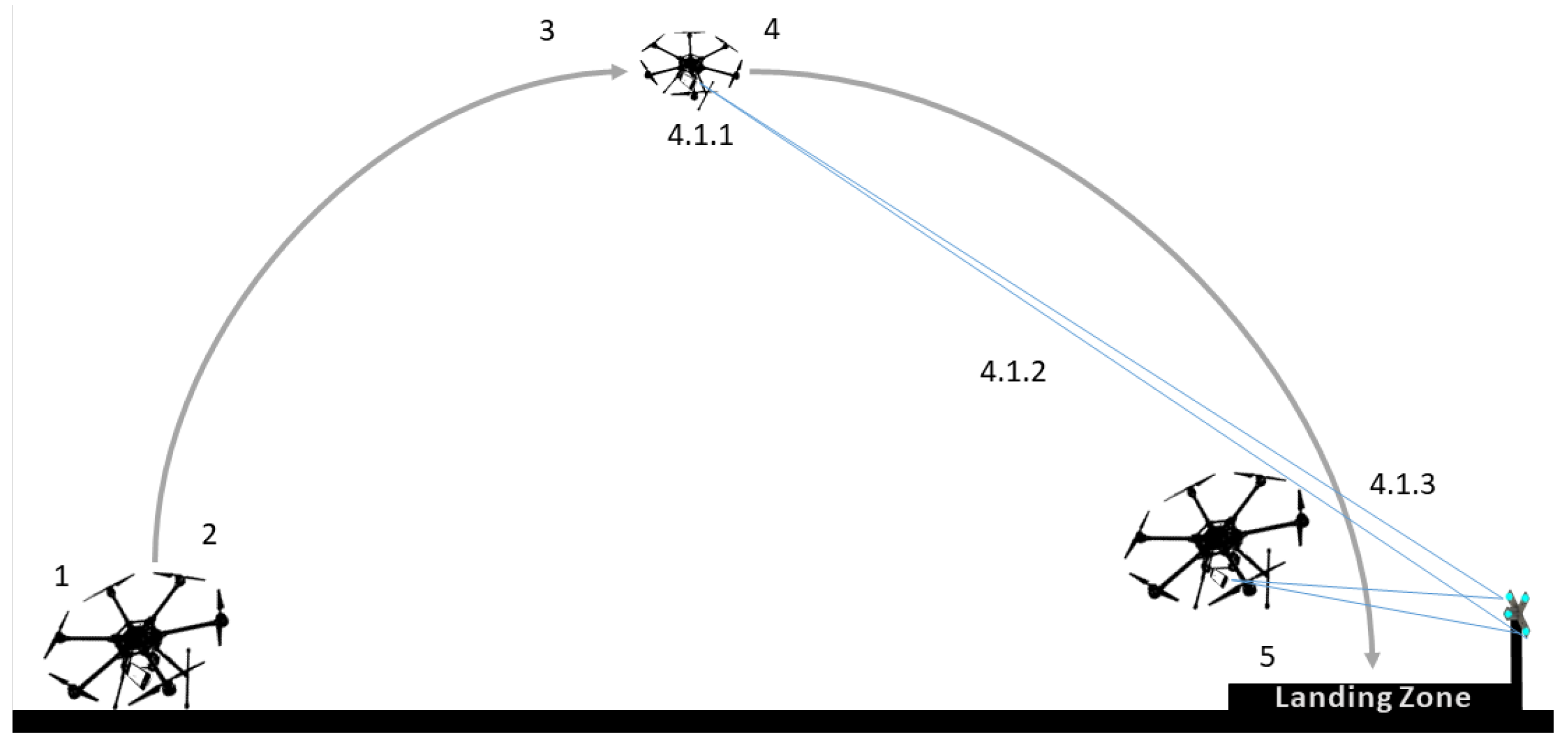
  • Precise landing from a high altitude (100 m) to a static target on ground using SVGS, IMU, and barometer measurements in sensor fusion, following the concept of operation shown in Figure 2. GPS-based corrections are limited to reject wind disturbances.
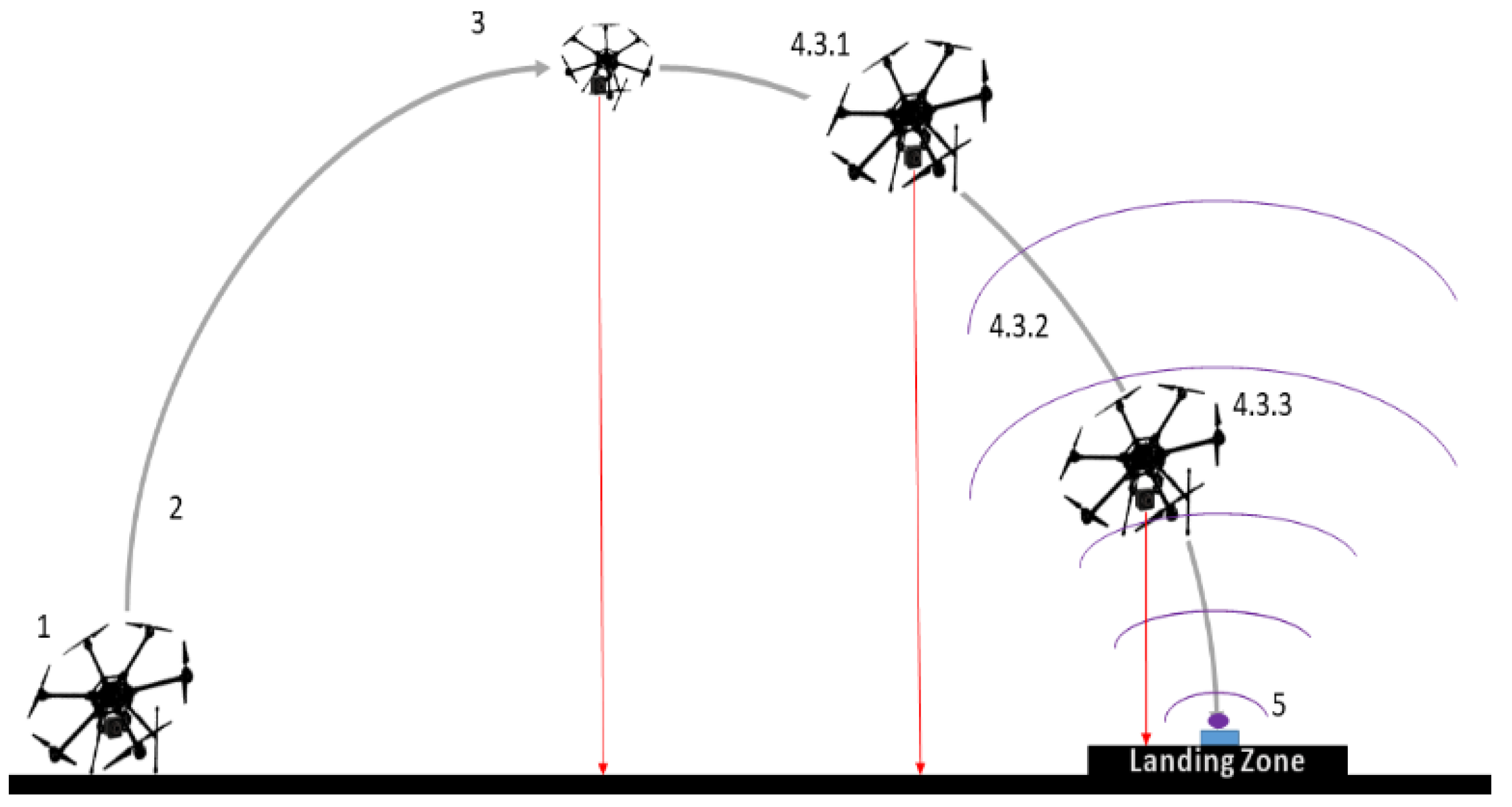
  • Precise landing from 40 m to a static infrared beacon on ground, using IMU, a barometer, a 2D infrared sensor, and range sensor measurements in sensor fusion, following the concept of operation shown in Figure 3. GPS-based corrections are limited to reject wind disturbances. This provides a baseline for comparing landing performance, against state of the art commercially available technology.
The numbers in Figure 2 and Figure 3 correspond to flight operations steps, namely: (1) perform safety checks, take-off; (2) stabilize at desired high altitude; (3) localize landing beacon; (4) initiate autonomous landing routine; and (5) start proximity operations and land. The mission sequences for autonomous landing (4) are outlined in Figure 4 and Figure 5.

2.3. UAV Hardware Description

The UAV used in these experiments is described below:
  • Avionics: PX4 flight control unit (FMU-V6X), LattePanda Delta3 companion computer, UBLOX F9P GNSS module, Futaba T6K 8-Channel 2.4 GHz RC System, and Holybro SiK V2 915 MHz 100 MW Telemetry Module.
  • Motors and frame: Tarot X8-II Frame, Tarot 4114/320KV Motors, OPTO 40A 3-6S electronic speed controllers, Tarot 1655 folding electric motor propellers (16 in), 4S-5000 mAh Li-Po battery, and 6S-22000 mAh Li-Po battery.
  • Navigation Sensors: for SVGS: Samsung Galaxy S8 smartphone (host platform), IOIO Bluetooth to USB link (communication bridge); and for Infrared Beacon Landing: IR-LOCK PixyCam, TFmini Plus LiDAR Rangefinder.
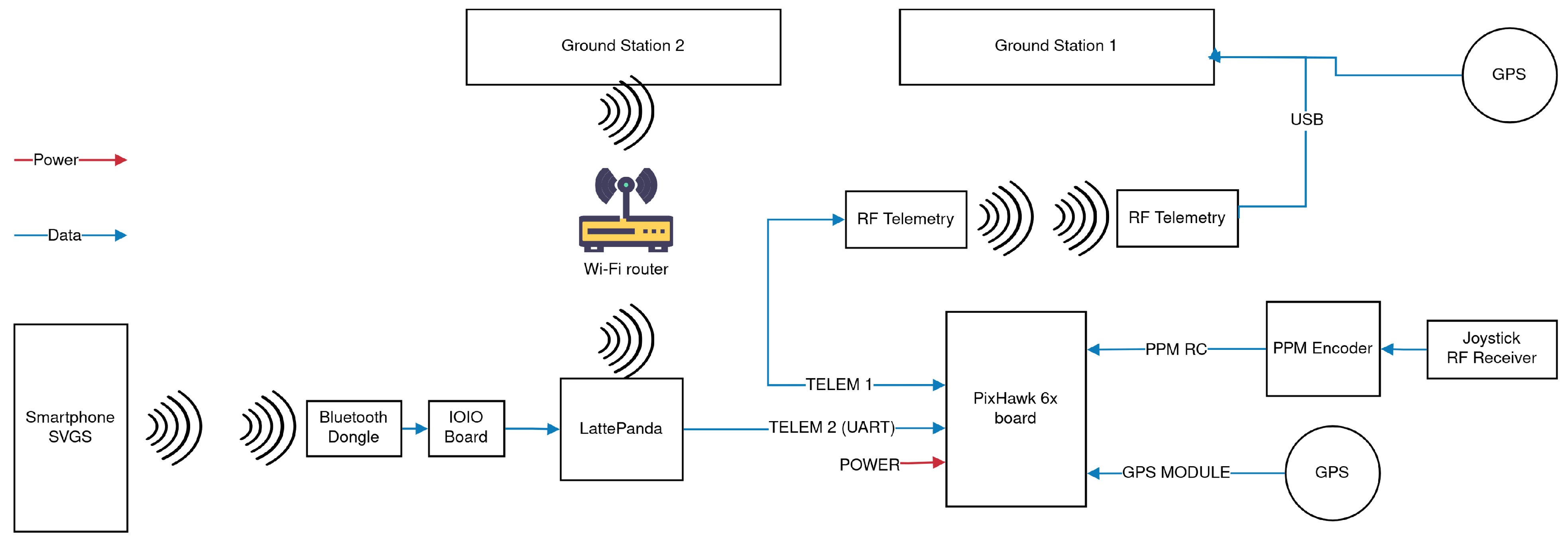
The interconnection diagram for the UAV (SVGS approach) is shown in Figure 6. For the IR beacon and range sensor approach, the SVGS sensor is replaced by the IRlock PixyCam and TFmini LiDAR, connected to the PX4 FCU using UART and i2C, respectively.

2.4. State Estimation and Sensor Fusion

Figure 7 outlines the Extended Kalman Filter (EKF2) and output prediction algorithm used in the PX4 platform [30].
EKF2 uses a ring buffer to synchronize measurement timestamps within a delay horizon, allowing for the fusion of various sensors acquired at different rates in a standard Extended Kalman Filter manner. The estimated states are used as references for the position setpoint commands sent from the companion computer to the flight controller. The SVGS latency from measurement to flight controller is ≈175–230 ms. The PX4 open-source flight controller allows for the arbitrary tuning of the delay horizon by the user. This investigation used EKF Replay, an offline PX4 tool, to select the delay optimally based on the innovation test, which mitigates and attenuates any potential drawbacks due to latency between SVGS and the PX4 flight controller.
Output Predictor: the complex dynamics of UAVs require fast state estimation to perform effective rate control. Output Predictor states are propagated based on IMU buffered data. The division between core states (IMU) and other sensor states has been previously introduced in sensor fusion literature using ring buffers [31]. EKF2 rejects or accepts measurements based on their quality relative to the current state estimate (innovation consistency test). The maximum innovation threshold is a parameter for each sensor measurement, defined as the maximum Mahalanobis distance corresponding to a user-defined gate size [1,30]. Table 1 shows the gate sizes (in standard deviation units) used for the High-Altitude Landing experiments.
The gate size imposed on GPS measurements forces x and y position estimates to rely significantly on SVGS or IR-LOCK due to their relaxed gate size. The SVGS covariance matrix was previously characterized for a 3-DOF system (x, y, θ ) in [32]; thus, the covariance used as floor covariance for the 6-DOF system was:
Θ 3 D O F = μ σ θ 2 σ θ ˙ σ θ σ x ˙ σ θ σ x ˙ σ θ σ y ˙ σ θ σ y ˙ σ θ σ θ ˙ σ θ σ θ 2 σ x ˙ σ θ σ x ˙ σ θ σ y ˙ σ θ σ y ˙ σ θ σ x ˙ σ θ σ x ˙ σ θ σ x 2 σ x ˙ σ x σ y ˙ σ x σ y ˙ σ x σ x ˙ σ θ σ x ˙ σ θ σ x ˙ σ x σ x 2 σ y ˙ σ x σ y ˙ σ x σ y ˙ σ θ σ y ˙ σ θ σ y ˙ σ x σ y ˙ σ x σ y 2 σ y ˙ σ y σ y ˙ σ θ σ y ˙ σ θ σ y ˙ σ x σ y ˙ σ x σ y ˙ σ y σ y 2
Θ 3 D O F = 1.6 0.000027 0.000003 0 0 0 0 0.000003 0.000016 0 0 0 0 0 0 0.006 0.0069 0 0 0 0 0.0069 0.0552 0 0 0 0 0 0 0.0051 0.0003 0 0 0 0 0.0003 0.0405

Sensor Fusion of SVGS Non-Deterministic Intermittent Measurements

There are several challenges in the integration of SVGS measurements as part of the state prediction. SVGS requires line of sight, which leads to SVGS measurements being intermittently available. SVGS runs on an Android device, which leads to small fluctuations on its nominal update rate, as described in [29]. If SVGS measurements are acquired at a constant nominal sampling rate, the UAV does not lose line of sight with the SVGS beacon and the host-CPU is not constrained (the SVGS sampling rate on a Samsung Galaxy S8 as host platform is ≈6–15 Hz, depending on the number of blobs identified per picture, [1]); then, EKF fusion proceeds as expected in the PX4 FCU. If IMU measurements were not subject to inherent temporal drift, the accuracy of propagated states from the Output Predictor would tolerate a longer delay window in the EKF2. The modifications introduced to achieve sensor fusion of SVGS measurements are:
(a)
A Kalman Filter in the companion computer corrects SVGS sampling frequency values before fusion at the flight controller EKF2. A solution similar to the one described in [1,2] is used, while in this investigation error messages are omitted from being parsed by the companion computer’s Kalman Filter and consequently sent to the flight controller’s EKF2: when SVGS cannot calculate c V using the selected blobs, it outputs a packet containing a numerical error code to the companion computer.
(b)
EKF2 parameters are tuned to avoid unnecessary resets: if state estimates diverge at t = k , the state estimate x ^ k is removed and the estimation is reinitialized. This explains the gate size parameters used for the magnetometer and barometer in Table 1.
The PX4 EKF algorithm has a built-in option to define gate size for both GPS and external vision sensor (SVGS, in this case), as well as to choose which internal or external sensor is the primary height and heading source. By selecting a very strict gate size for GPS estimates and a lenient gate size for the external vision sensor, as well as defining the primary height source as the barometer and fixed heading based on the FCU magnetometer, the influence of GPS in the fusion can be arbitrarily reduced without need to make changes to the FCU’s firmware. GPS RTK does not have cm accuracy throughout the entire trajectory, having much closer accuracy to the theoretical best when closer to the ground station.

2.5. Motion Controller and Hardware-Software Implementation

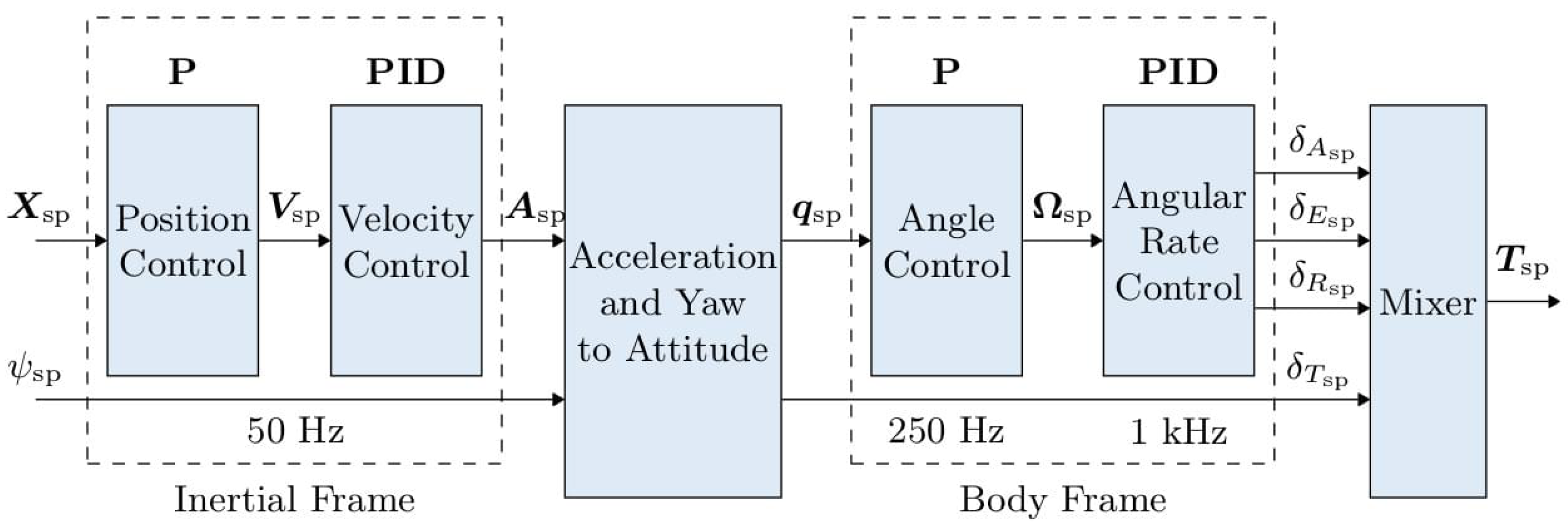
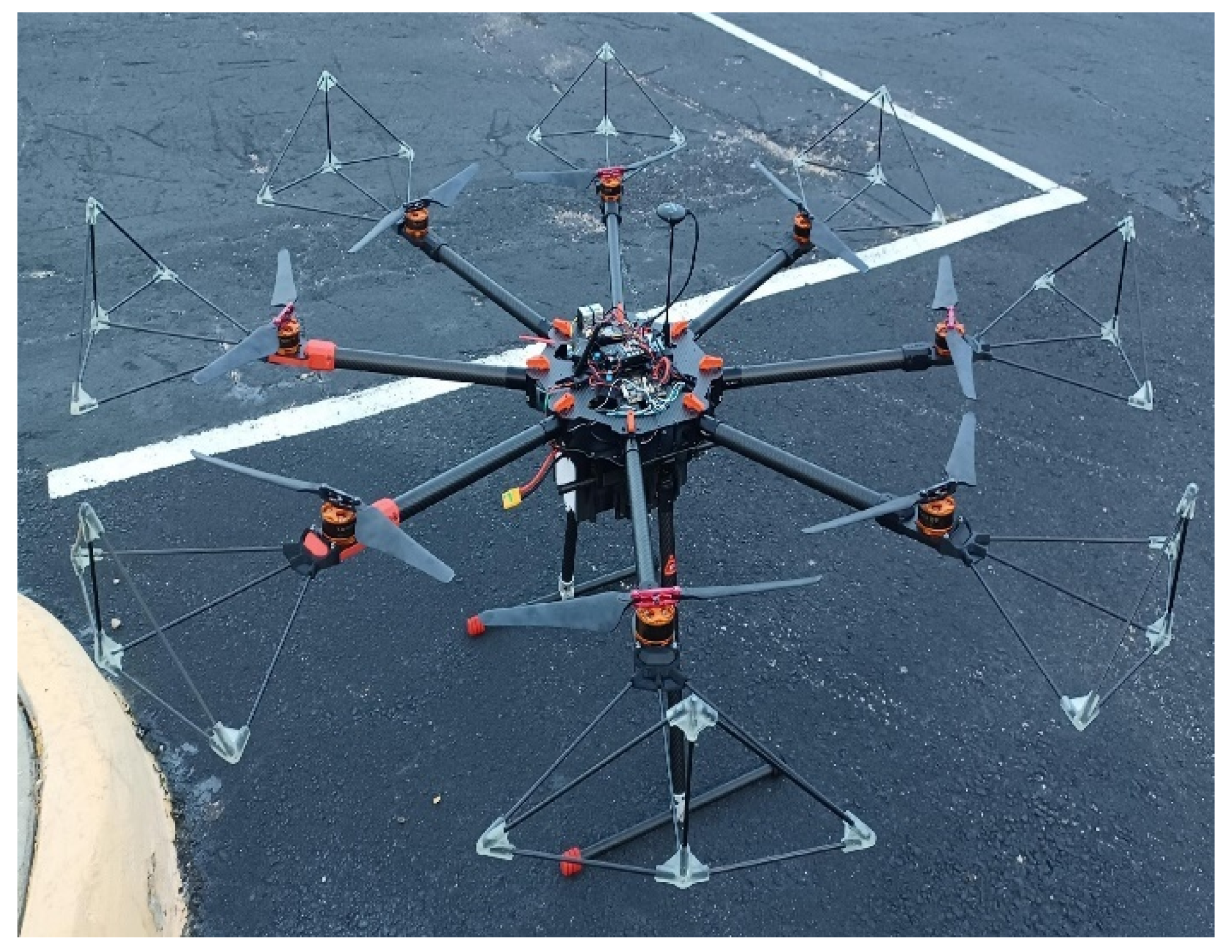
PX4 autopilot software used in this study (Release v1.13.3) provides a cascade PID control for multicopters that has been previously used in autonomous landing [2]. Position setpoints are sent from the companion computer to the flight controller and are adjusted by the outer P block in Figure 8. Body frame control parameters are autotuned based on IMU low-pass filtered data and estimated bias correction. No modifications were made to the PX4 flight stack, but changes to several settings were introduced to implement the proposed sensor fusion (Section Sensor Fusion of SVGS Non-Deterministic Intermittent Measurements). Specifications of the FAA Class 2 UAV used in the study (Figure 9) are shown in Table 2.

2.5.1. SVGS Landing Beacons for High-Altitude Landing

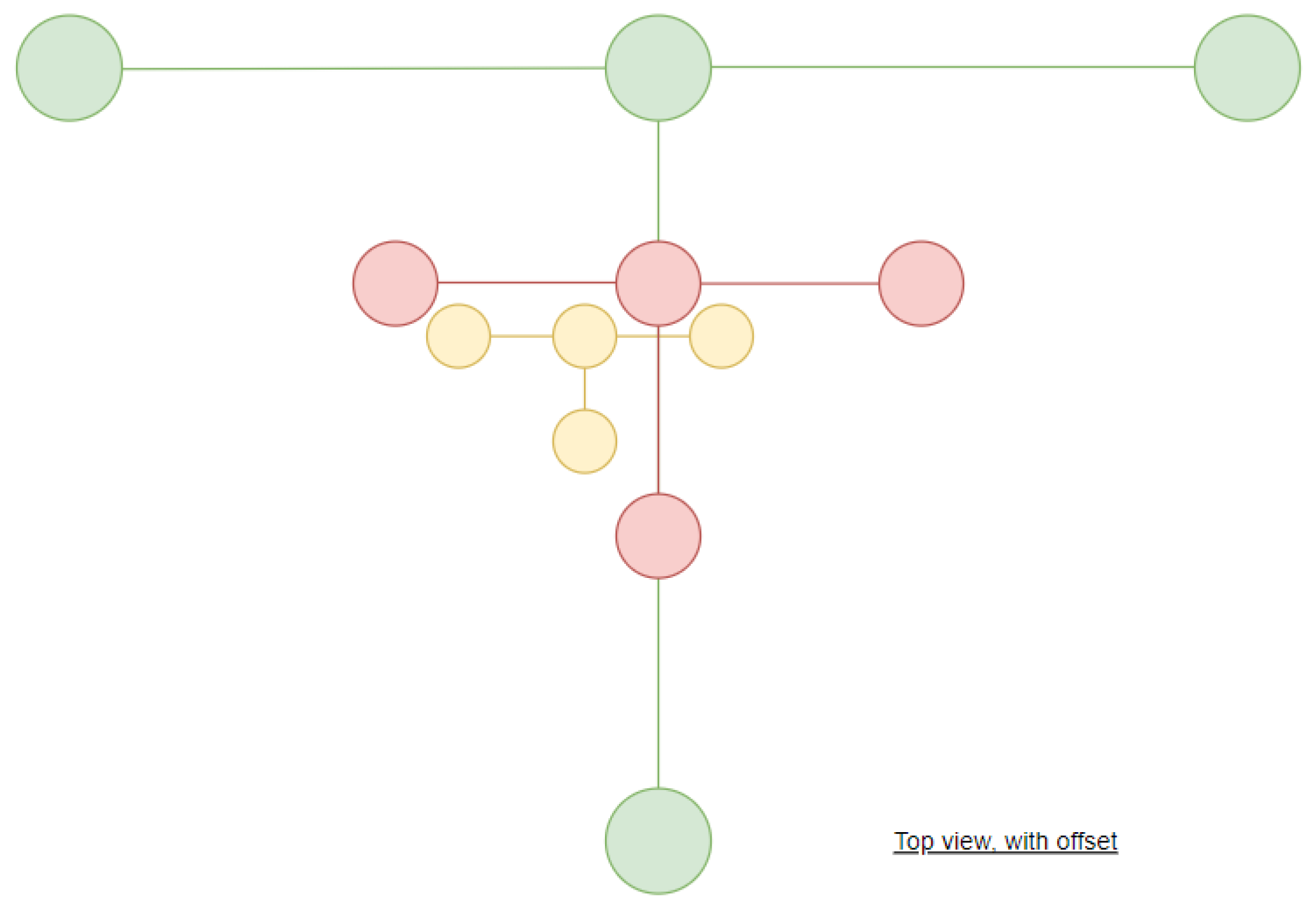
SVGS requires scaling beacon dimensions depending on operating range (the distance from camera to beacon). Figure 10 shows the SVGS 3-beacon configuration used in this study, and Table 3 shows the operating range and LED locations for each SVGS beacon, measured from their corresponding centers (origin).
SVGS operation requires the correct discrimination of 4 separate blobs. This is only possible within a certain range of distances between the target and camera for a given beacon dimension. To operate over a large range, targets of different dimensions are used to cover overlapping range intervals during the mission—in this case, three different size targets, described in Figure 10 and Table 3. The effect of beacons’ appearance in a High-Altitude Landing scenario can be minimized by the algorithm’s LED sensitivity, as discussed in [1], and the blob-detection mechanism, as mentioned in Section 2.1.2. Filtering blobs by color and intensity guarantees convergence if the blob alignment and geometric requirements are met. The images captured by SVGS’ host platform were scaled to an aspect ratio of 800 × 800 . The baseline method for autonomous landing uses a combination of infrared camera, infrared beacon, and range sensor (IR-LOCK). The MarkOneV3 infrared beacon was used; COTS beacons are designed for a maximum tracking altitude of 40 m, which leads to significant differences in landing routines, as described in Section 2.5.5.

2.5.2. Avoiding Spurious x and y Position Estimates

Both IR-LOCK and SVGS provide x and y measurements of a target with respect to the camera frame. This does not necessarily represent the x and y position of the UAV in the local coordinate frame, even after proper rotation, since the drone is not always aligned with the target’s center. Perfect alignment is unlikely during the entirety of the mission, but the relaxed gate size used allows enough measurements to be fused. The following method was employed to use x, y IR-LOCK, and SVGS measurements to obtain the drone x and y local position measurements in the vehicle coordinate frame:
  • Achieve sufficient target alignment.
  • Reset EKF2 to include SVGS or IR-LOCK target position measurements in the local UAV frame.
As mentioned in Section Sensor Fusion of SVGS Non-Deterministic Intermittent Measurements, if target line of sight is available, one could grab two measurements from SVGS or IR-LOCK and obtain their difference as the UAV position changes in the local frame after proper rotation.

2.5.3. SVGS Frame Transformations

SVGS provides the 6-DOF vector of the target with respect to the camera frame. The transformation suggested in [2] was revised to account for x, y, z coordinates and IMU calibration. The new approach considers the coordinate frame attached to the camera perspective center different than the vehicle’s IMU body frame.
Lemma 1 
(SVGS Transformation). Let c m R ( 3 × 3 ) be the rotation matrix from the SVGS camera frame to the UAV-IMU body frame, and let c m T ( 1 × 3 ) be the translation vector between origins. Then, SVGS-UAV x, y, z measurements in the camera frame, c Z , are written in the body frame as follows:
m Z = c m R c Z + c m T
In practice, c m R is obtained from the difference in orientation angles between the FCU IMU frame (after calibration) and the frame geometrically aligned with SVGS. c m T is a fixed translation given by the position difference between the FCU and SVGS host platform. This transformation does not alter the SVGS covariance.

2.5.4. Autonomous Landing Routine

Comparing the target approach trajectory between SVGS and infrared beacon landing does not provide an effective metric for performance comparison since the COTS autonomous landing solution does not account for exogenous environmental disturbances, such as varying wind speeds. The COTS landing routine will attempt landing even without final target confirmation, which often results in poor landing precision since EKF2 can not fuse x, y coming from the infrared camera, as shown in Figure 11. A high-level description of the infrared camera and range sensor autonomous landing routine is:
  • Go to a predetermined position where the IR beacon should be visible.
  • If the beacon is visible, align with it in a horizontal plane. If not, search for the beacon for a predefined number of times. The maximum number of search attempts was set to 20.
  • If beacon sight is locked, start descending on top of the beacon. If not, and maximum search attempts have been reached, land.
  • If beacon sight is lost during descent but UAV is near ground, land.
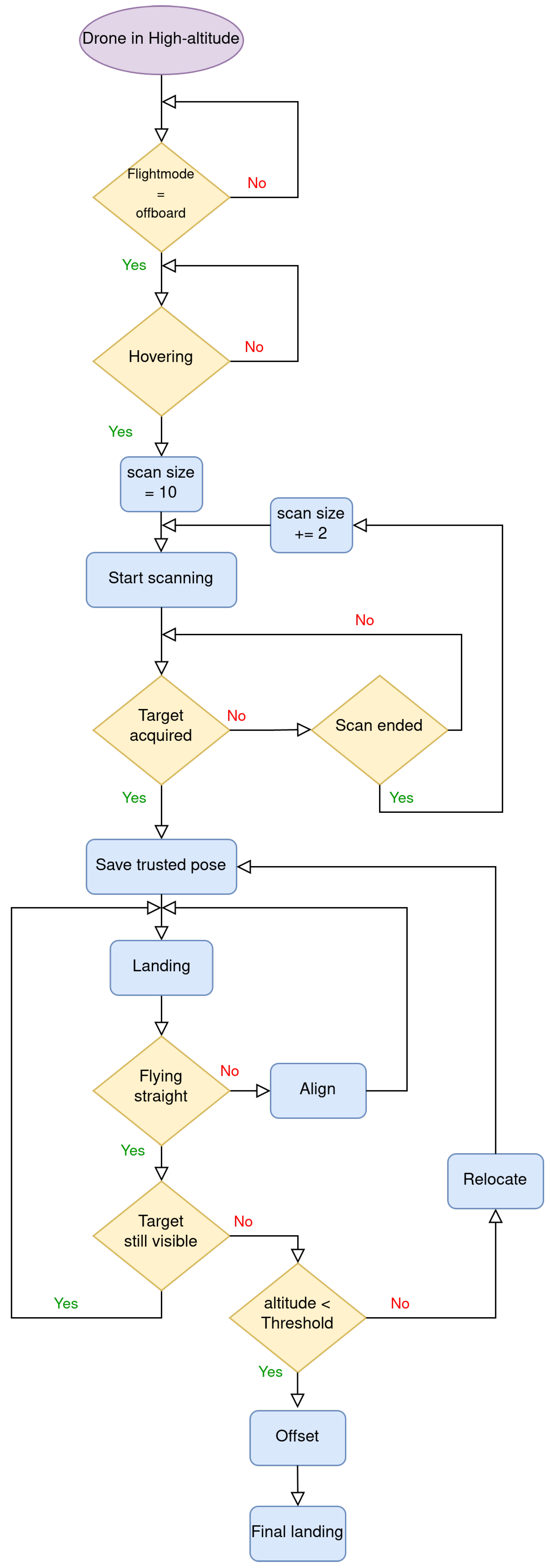
The SVGS high-altitude autonomous landing routine is a disturbance-tolerant algorithm that uses the Front, Left, Up (FLU) local coordinate frame of the UAV. A high-level outline of the routine is:
  • The UAV scans, searching for the landing target, increasing the search radius until the target confirmation is achieved.
  • The UAV aligns with the target center and starts descending.
    • If the target line of sight is lost during descent, relocate to the last position at which the target sight was confirmed on the X Y -Plane (Local coordinate F L -Plane). If the target sight cannot be recovered, attempt to relocate using the x, y, z coordinates (f, l, u). Complete relocation often triggers an EKF2 reset.
  • At 20 m altitude, the UAV offsets and aligns with the Short-Range Target (SRT), beginning the final approach.
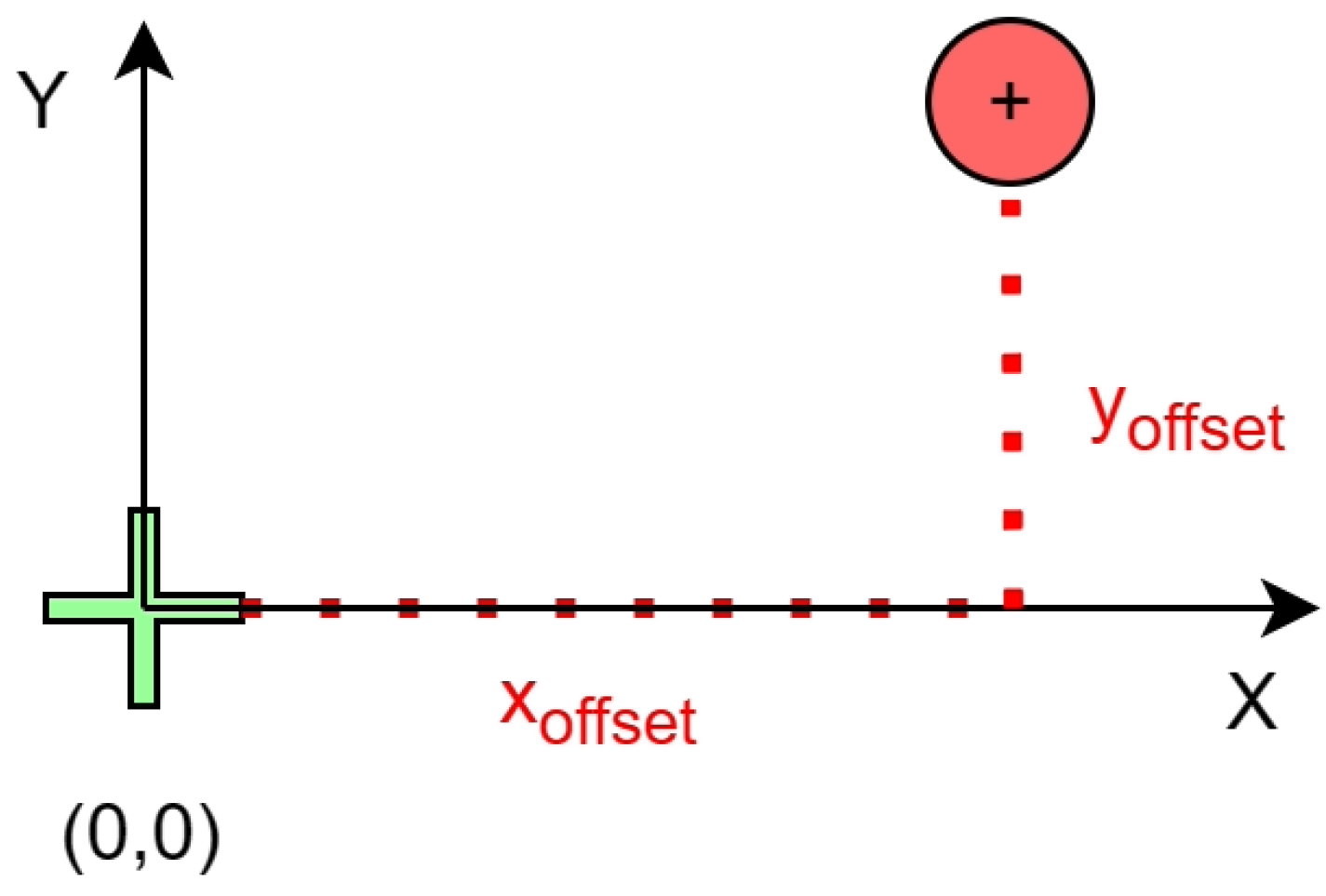
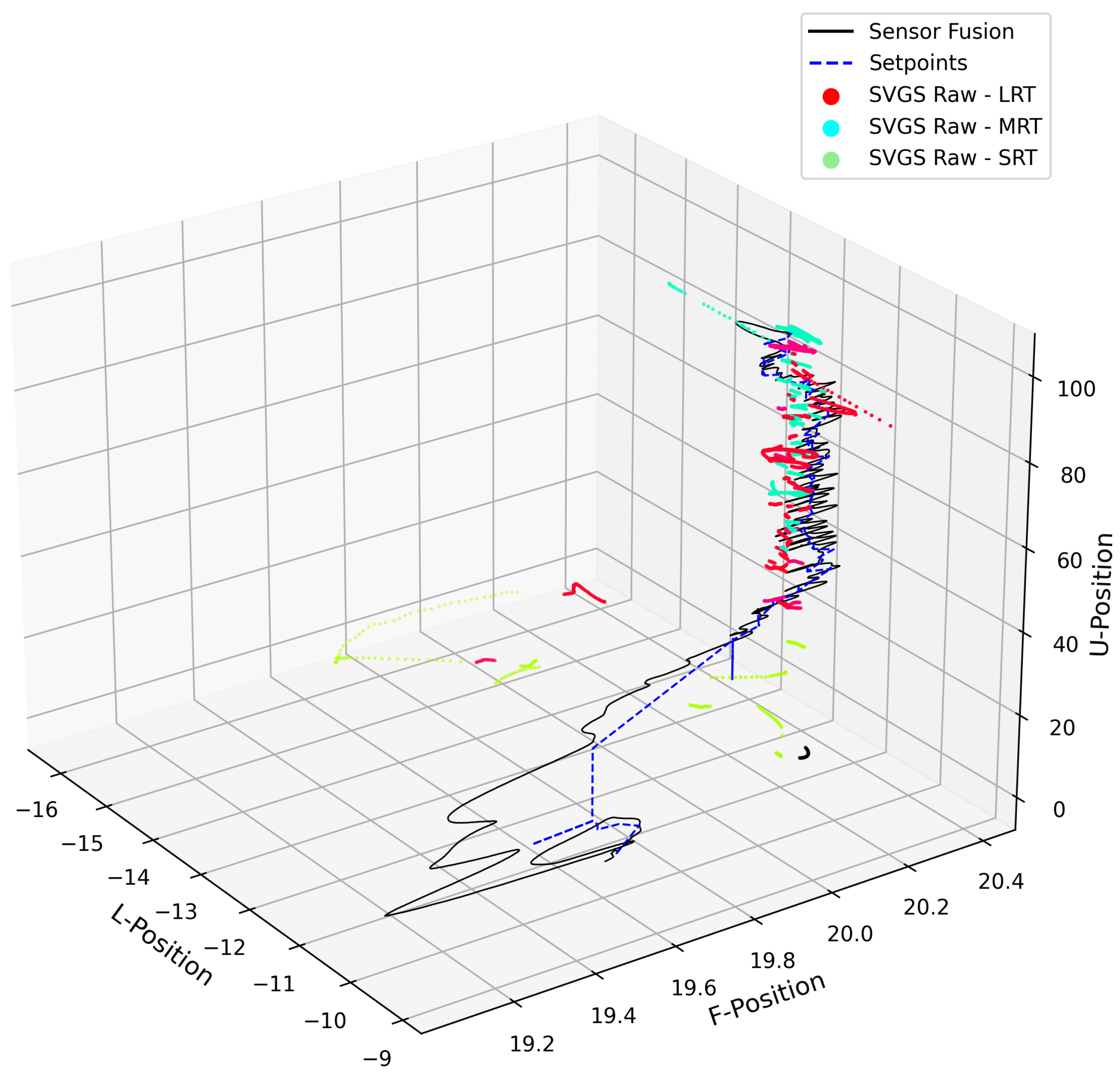
  • At ≈3 m altitude, the UAV performs a final offset maneuver. Offset values are selected to improve target sight during final landing approach; transmitted values to EKF2 are corrected to avoid landing on top of the target. The offset maneuver is depicted on Figure 12.
  • Complete landing.
The flow diagram on the SVGS autonomous landing routine is shown on Figure 13.

2.5.5. Autonomous Landing Framework

The autonomous landing framework differs depending on the method (SVGS or a combination of an infrared camera and range sensor), yet shared elements exist. Common aspects (CAs) are presented below:
CA1 
Ground Operations and Monitoring
This investigation used the open-source QGroundControl software (Version 3.5) (Ground Station 1 in Figure 6) to monitor telemetry packets from the FCU and to visualize the approximate UAV trajectory. The companion computer running the autonomous routines in the UAV was monitored via remote access by the long-range WiFi network (Ground Station 2, in Figure 6).
CA2 
ROS Noetic pipeline and Data Acquisition Node
The autonomous landing routine was developed as custom ROS Noetic nodes bridged by the MAVlink drone communication protocol using the standard wrapper MAVROS [33,34,35]. The communication pipeline is similar to the approach presented in [1,2]; however, functionalities and the information pipelined greatly differ. These changes will be discussed in the next subsections.
A central part of the software stack for both landing methods is the ROS data acquisition node, whose primary function is to log information from the FCU sensors, SVGS measurements (from the host platform), and locally calculated setpoints. This approach complements the standard FCU data acquisition, allowing data verification on both communication ends. The ROS nodes defined in the SVGS automated landing package are:
  • motion_control_drspider: Implements logic for UAV motion control during the autonomous landing phase. It is also responsible for sending position or velocities setpoints to the “px4_control” node.
  • routine_commander_drspider: Coordinates which phase and/or portion of the motion routine must be active if certain conditions are met.
  • transformations_drspider: Applies rotations to collected sensor data as needed. Used mainly to convert SVGS values before and after topic remapping (sensor fusion).
  • svgs_deserializer_drspider: Converts serial data packets from SVGS and publishes output as a stamped pose message on the topic “target” with the data type of posestamped, a data structure used by ROS that includes a timestamped x, y, z positions, covariance, and orientations. It also applies a Kalman filter to SVGS raw values.
  • px4_control_drspider: Obtains setpoints and processed sensor data from motion control nodes and sends them to the flight computer at 30 Hz.
  • data_recording_drspider: Subscribes to several variables and records them to a CSV file at 25Hz for data and error analysis.
The motion control ROS node for SVGS high-precision landing is outlined in Algorithm 2 and runs at a 30 Hz loop rate. Algorithm 2 executes a square perimeter search of the SVGS landing beacon in a lawn-mower pattern. The search stops if the target is found, i.e., s c a n B o o l m s g . B o o l d a t a becomes false. Algorithm 2’s duration time is purposefully long (it includes Sleep functions) so that a new upcoming message updating s c a n B o o l is received at the position where the SVGS beacon is found. If the beacon is not found, the routine commander node re-initializes the algorithm using a different square side size. The increment during the scan (0.5 j) accounts for the autonomous maneuver velocity norm as well as SVGS’ image aspect ratio. It considers potential transient effects caused by the autonomous landing routine, which are also attenuated by conducting the maneuvers at low speeds (Table 2). The choice of increment was based on the following:
  • Accuracy. In UAVs autonomous routines, commanding a set point in a loop with an abrupt exit condition may lead to getting caught in an endless loop. For instance, let S P denote a 3-dimensional array with a set point in the FLU coordinate system, and let c u r r _ p o s denote the UAV’s current position in the same frame. If the condition | | c u r r _ p o s S P | | < ϵ , ϵ [ 0 , 0.01 ] ) is imposed, the drone may hover for an undetermined amount of time, depending on position estimate quality. Commanding two set points that are close to each other is essentially commanding the same set point: a minimum difference between two set points is required to guarantee actual UAV motion.
  • Coding Interface (ROS-MAVROS-PX4). If one commands a new set point and during that Δ S P the UAV gains momentary sight of the target, one would have to command the UAV back to the sight position for a large Δ S P instead of having the UAV stop exactly at the target sight position. Thus, a large Δ S P is not desirable. This is also due to the communication latency within ROS nodes, aggravated by the fact that ROS Noetic uses a central node to communicate with the other nodes [30,33,34].
  • UAV System. The value selected for Δ S P needs to consider the UAV dimensions (Table 2). Two set points that are too similar could create destabilizing UAV behavior (chatter), which can be aggravated by the size and weight of the aerial vessel.
In summary, a search for an optimal Δ S P at 100 m altitude endangers the mission for no significant gain in performance. Values above and closer to 1 j would cause the issues described in (2) and increase battery consumption, and values smaller than 0.05 j would cause the problems described in (1) and (3).
Algorithm 2 Scan Maneuver
  1:
s c a n B o o l m s g . B o o l
  2:
s q u a r e S i z e m s g . I n t
Require: 
h o v e r E n d e d and s c a n B o o l = T r u e
Require: 
T a r g e t A c q u i r e d and B e a c o n O r i g i n = F a l s e
  3:
if  i s q u a r e S i z e   then
  4:
       if  j s q u a r e S i z e  then
  5:
           if  i mod 2 = 0  then
  6:
               s p [ c u r r F , c u r r L + 0.5 j , c u r r U ] ▹ CurrF, CurrL, CurrU are the current local positions
  7:
               s e n d S e t p o i n t ( p , s p )
  8:
               s l e e p ( 3 )                             ▹ Next Position
  9:
         end if
10:
        if  i mod 2 0  then
11:
            s p [ c u r r F , c u r r L 0.5 j , c u r r U ]
12:
            s e n d S e t p o i n t ( p , s p )
13:
            s l e e p ( 3 )                             ▹ Next Position
14:
        end if
15:
         j j + 1
16:
    end if
17:
    if  j > s q u a r e S i z e  then
18:
         j 0
19:
         i i + 1
20:
         s p [ c u r r F + 0.5 i , c u r r L , c u r r U ]
21:
         s e n d S e t p o i n t ( p , s p )
22:
         s l e e p ( 3 )                              ▹ Next Position
23:
    end if
24:
    if  i s q u a r e S i z e  then
25:
         i 0
26:
         s c a n n e d P u b . p u b l i s h ( T r u e )                      ▹ Scan Ended
27:
    end if
28:
end if
Algorithm 3 outlines the align maneuver, as discussed in Section 2.4 and Section 2.5. This process is repeated every time the UAV is not sufficiently aligned. Algorithm 4 is invoked if the drone loses beacon sight during descent. It initially attempts a 2D relocation to a trusted position (previous known beacon location) and follows with a complete 3D relocation in case beacon sight is not reached. The relocation maneuver guarantees the robustness of the descent routine to external disturbances such as wind loads. If the UAV drifts sideways during landing due to exogenous disturbances such as strong winds, it can move back to the last trusted position. The routine commander ensures that the relocation maneuver is not invoked during the alignment or offset maneuver, especially during SVGS beacon transition (the transition from one beacon to the next triggered by altitude).
Algorithm 3 Align Maneuver
  1:
a l i g n B o o l m s g . d a t a
  2:
if alignBool, targetAcquired, and hoverEnded are True then
  3:
     t i m e x T i m e
  4:
    while  T i m e t i m e x 5  do
  5:
         u p d a t e d S P . t y p e p                        ▹ Postion Setpoint
  6:
         u p d a t e d S P . a r r a y [ S V G S F L U ]
  7:
         s e n d S e t p o i n t ( u p d a t e d S P . t y p e , u p d a t e d S P . a r r a y )       ▹ Align UAV with the Target
  8:
         s l e e p ( 1 )
  9:
    end while
10:
end if
Algorithm 4 Relocation XYZ
  1:
r e l o c a t e B o o l m s g . d a t a
Require: 
C u r r U U m i n and t a r g e t A c q u i r e d and l a n d i n g F l a g are F a l s e
Ensure: 
TrustedPose is Valid    ▹ Last local position with a valid SVGS Est.
  2:
if  r e l o c a t e B o o l i s T r u e   then
  3:
     s e n d S e t p o i n t ( p , [ T r u s t e d P o s e F , T r u s t e d P o s e L , C u r r U ] )
  4:
     s l e e p ( 2 )                   ▹ Relocate - XY-Plane First
  5:
    if  t a r g e t A c q u i r e d i s F a l s e  then
  6:
         s e n d S e t p o i n t ( p , T r u s t e d P o s e F L U )           ▹ Relocate - XYZ
  7:
         r e l o c a t e d P u b . p u b l i s h ( T r u e )
  8:
    end if
  9:
end if
At the end of the landing routine, Algorithm 5 is called to offset the UAV from the SRT (Figure 12) since landing on top of the beacon would damage both the UAV and beacons. A similar version is used to offset the UAV from MRT to achieve the target-lock on the SRT.
Algorithm 5 Offset Maneuver
  1:
o f f s e t F l a g m s g . d a t a
Require: 
C u r r U U m i n
  2:
if  o f f s e t F l a g and l a n d i n g F l a g are F a l s e  then  ▹ Check if Offset flag is true
  3:
     t i m e x t i m e ( )
  4:
    while  t i m e ( ) t i m e x < 5  do
  5:
         s p [ c u r r F + 1.5 , c u r r L + 1.5 , c u r r U ]
  6:
         s e n d S e t p o i n t ( p , s p )
  7:
         s l e e p ( 2.5 )           ▹ Send 2 requests of 1.5 m on each axis
  8:
    end while
  9:
     o f f s e t B o o l T r u e
10:
end if
Algorithm 6 outlines the landing maneuver: the UAV vertical descent. The UAV decreases altitude at constant increments before the final offset from the SRT is confirmed. At this point, the UAV is commanded to position lower than ground, which allows the FCU to detect that landing has taken place and disarm the motors.
Algorithm 6 Landing Maneuver
Require: 
( l a n d i n g F l a g h o v e r E n d e d are T r u e ) ( r e l o c a t e B o o l is F a l s e )
  1:
if  C u r r U U m i n is T r u e ) ( o f f s e t B o o l is F a l s e )  then
  2:
     s p [ c u r r F , c u r r L , c u r r U 0.7 ]                 ▹ Descend
  3:
     u p d a t e d S P . t y p e p
  4:
     u p d a t e d S P . a r r a y s p
  5:
else
  6:
    if  ( F i n a l o f f s e t B o o l is T r u e ) )  then
  7:
         s l e e p ( 2 )               ▹ Wait for Offset to be fully complete
  8:
         s p [ c u r r F , c u r r L , c u r r U 5 ]     ▹ Send a lower-than-ground position
  9:
                    ▹ Drone will detect landing and disarm
10:
         u p d a t e d S P . t y p e p
11:
         u p d a t e d S P . a r r a y s p
12:
    end if
13:
end if
14:
s e n d S e t p o i n t ( u p d a t e d S P . t y p e , u p d a t e d S P . a r r a y )
15:
s l e e p ( 1 )
The autonomous landing procedure for the infrared camera and range sensor approach is based on manufacturer’s software. The logic for the landing maneuver is implemented at the flight controller instead of the companion computer; ROS nodes are not involved.

3. Results

Comparison of Precision Landing Performance

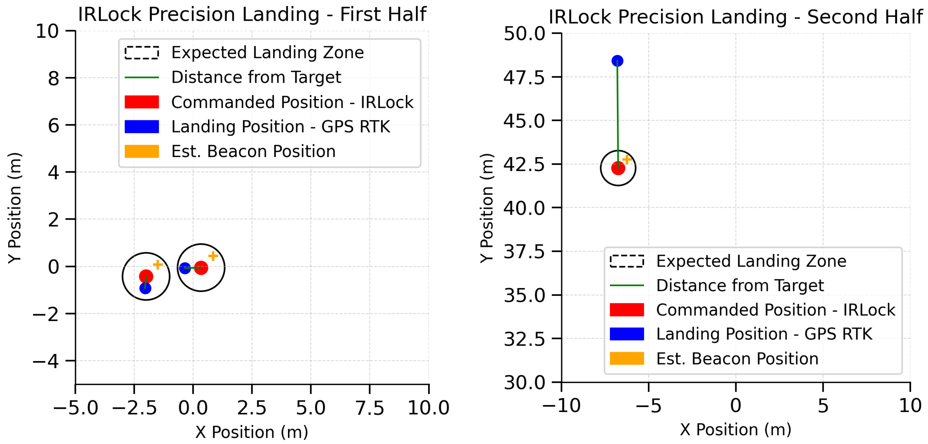
The main comparison will be based on the response to the landing position setpoint, the actual landing location (according to raw GPS RTK data), and the position of the landing beacon. Three repetitions of autonomous landings were carried out to investigate the landing accuracy. The starting and commanded landing points for each method are shown in Table 4. The results for SVGS autonomous landings are shown in Figure 14, and results for three IR Lock landings are shown in Figure 15.
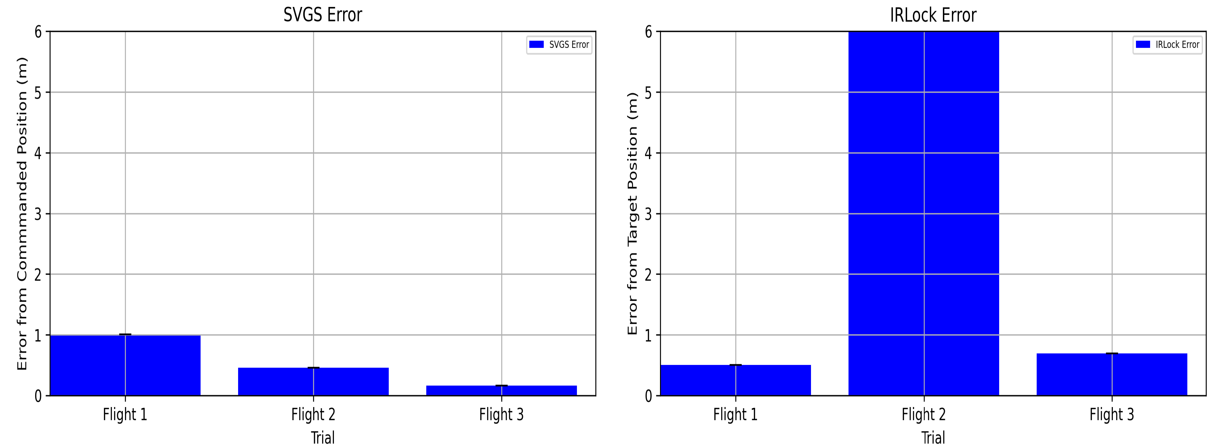
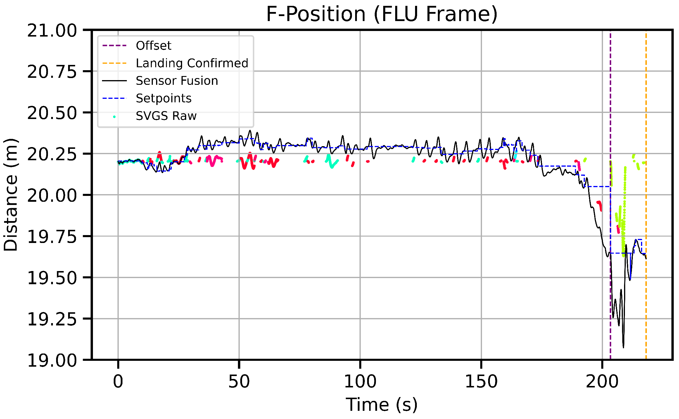
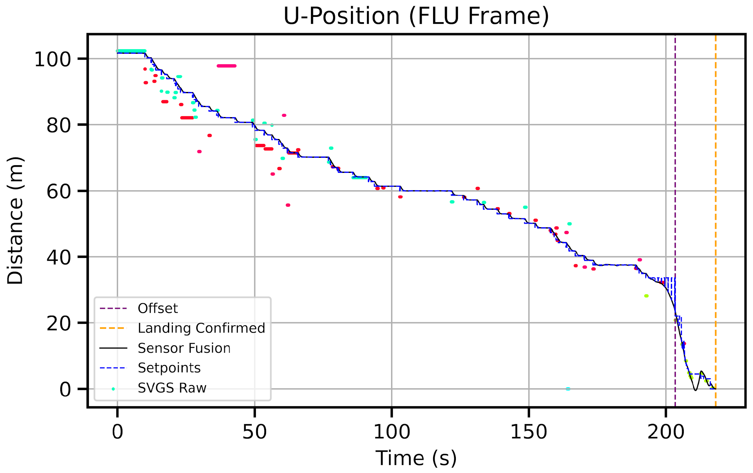
Figure 16 shows a comparison of landing error: commanded position minus actual landing position for each approach. Figure 17, Figure 18, Figure 19 and Figure 20 show UAV trajectory in the FLU frame during SVGS automated landing. Traces in light blue, red, and light green represent raw measurements from SVGS. The solid line shows the sensor fusion estimate from the PX4 Extended Kalman Filter (EKF2), while the dotted blue line indicates the commanded setpoints. The results from flight tests demonstrate that autonomous landing can be reliably achieved using SVGS, despite significant wind disturbances experienced during testing. SVGS raw values are displayed in the FLU-frame with the following color encoding (based on the blob HUE value): cyan corresponds to the Long-Range Target, red and magenta to the Medium-Range Target, and green to the Short-Range Target.
For IR-LOCK, Flights 1 and 3 show that IR-LOCK can reliably land from 55 m. altitude. However, in Flight 2, IRLock significantly fails to achieve precision landing since it loses beacon sight.

4. Discussion

4.1. SVGS Navigation and Sensor Fusion

Considering typical wind disturbances at high altitude, it would be impossible to achieve High-Altitude Landing from altitudes in excess of 100 m without some kind of GPS support. The participation of GPS, however, was weighed in the fusion algorithm to provide strong preference to SVGS readings (instead of GPS) when both measurements were available. It must be noticed that the main motivation of this project was to demonstrate and assess SVGS as an alternative to infrared beacon/LiDAR technology in planetary landing: the typical High-Altitude Landing scenario envisioned by NASA does not have to deal with any wind disturbances, so the need of GPS disappears. High-Altitude Landing on earth has significant challenges in the form of atmospheric disturbances and poor visibility that would not be present in a planetary landing scenario.

4.1.1. EKF2 Resets and Instability

A potential concern regarding the estimation method described in Section 2.4 and Section 2.5 is EKF2 instability. This is addressed by maintaining GPS present in the sensor fusion, even at a very strict gate size. The approach is similar to a UAV with an optical flow sensor and GPS performing a multi-phase mission where a segment is GPS-denied and another is not. In this investigation, SVGS acts as GPS (absolute position reference) and GPS acts as the optical flow sensor in the analogy. Instability due to a lack of valid estimations may still occur if SVGS target-lock is assumed after considering a small time window of valid SVGS readings as target-lock.
The Pixhawk-FMU6x FCU has three IMUs, allowing for the implementation of multiple EKF2 instances. If one instance fails, it is always possible to rely on another one. The change of reference frame during operation is not an issue since position setpoint commands are created based on local position data published from the FCU to the companion computer. If the reference changes, local position values reflect the change.

4.1.2. EKF2 Drift Correction with SVGS

A gate-free continuous fusion of intermittent sensor measurements can degrade estimate quality and UAV performance [17], but selective fusion can correct drift in estimations. The proposed approach with SVGS shows that even sporadic fusion, tuned by EKF2 gate size in absence of beacon-lock, can act as a drift corrector. A piecewise-continuous gate-controlled fusion of SVGS by Kalman filter with high weight to SVGS measurements during beacon-lock periods fulfills the EKF2’s sampling requirements at the FCU. In a worst-case scenario in which SVGS’s low sampling frequency is not mitigated and gate size is declared large, some improvement in overall positioning accuracy can still be expected even with intermittent measurements, as discussed in [1,2,29,32].

4.2. SVGS Beacon Transition

Transitioning from one SVGS beacon to another based on range is challenging in the current implementation of SVGS. The companion computer receiving SVGS readings cannot force SVGS to ignore other beacons present on the image plane based on altitude, as shown in Figure 17, Figure 18 and Figure 19, where both MRT and LRT beacons are alternatively detected (red and light blue dots). This is partly mitigated by placing the beacons in a concentric pattern as shown in Figure 10. For the SRT, the optimal offset from the center was estimated empirically, and the value was used in the landing routine so that only four same-color blobs in the image are from the desired beacon. Although this did not completely eliminate SVGS from identifying other beacons (as seen on the FLU trajectory after initial offset), the companion computer’s local Kalman Filter accounted for the outliers.

4.3. SVGS Beacons and IR Beacon

Part of the reason why SVGS outperforms the IR-LOCK method with the range sensor is the target design. SVGS beacons reduce ambiguous interpretation due to their tetrahedral shape, which also allows for orientation extraction. In contrast, the IR-LOCK beacon does not provide information to extract the beacon orientation. Furthermore, the visibility of SVGS beacons is by far superior to that of the IR-LOCK beacon, hence the larger landing altitude. The infrared camera and range sensor combination could potentially increase its landing performance if the range sensor module were replaced by a state-of-the-art model, but this would defeat the low-cost sensor comparison of this investigation.

4.4. Influence of GPS RTK in Sensor Fusion

The influence of GPS in the sensor fusion was arbitrarily reduced without making modifications to the FCU’s firmware, as discussed in Section 2.4. To further illustrate this point, one can consider an extreme scenario where the local position estimate is incorrect due to primary height source, fixed heading, and/or potentially incorrect SVGS readings. During the local position estimate update, GPS RTK measurements would likely be rejected for being “too far” from the current distribution, effectively having arbitrarily small influence, and being of larger importance during events critical to mission safety, such as EKF reset.

4.5. GPS RTK Latency and SVGS Latency

To achieve sensor fusion in the PX4 framework, SVGS or any other external vision sensor must abide by the minimum 30 Hz sampling frequency imposed by the PX4 software [30]. On the other hand, GPS RTK latency is closer to 10 Hz. The difference is mainly due to the corresponding data pipelines: external vision sensor measurements are captured, parsed to their specific ROS node in the companion computer, streamed to MAVROS, and then transmitted to the flight controller, while GPS RTK measurements are directly transmitted to the FCU.

4.6. Future of SVGS for Guidance and Navigation of UAVs

The future implementation of SVGS to support GNC in UAVs requires important changes relative to its current Android implementation. The long term objective is to make SVGS available as a GNC sensor to a variety of robotic platforms, including VIO, SLAM, and space robotics applications for rendezvous, capture, and docking. Moving away from the smartphone implementation of SVGS will also improve the update rate and present better options for optics.

5. Conclusions

This paper illustrates the successful implementation of sensor fusion of SVGS with on-board FCU sensors in high-altitude autonomous landing. SVGS fused positioning accuracy is comparable to GPS RTK estimation (≈1 cm accuracy). The SVGS automated landing routine demonstrated robust, precise performance in High-Altitude Landing despite significant wind disturbances present during testing. Precision landing was successfully and reliably achieved under various wind conditions.
There are significant differences between vSLAM and SVGS as tools to support autonomous landing [36]; future SVGS applications could leverage aspects of vSLAM for improved sensor fusion in navigation applications. The main differences between SVGS and vSLAM are in (i) feature tracking, (ii) distance to landmark/target, (iii) state space and mapping, and (iv) accuracy. In summary: (i) vSLAM features are not predetermined. This means a vSLAM algorithm will select and track any feature in the image plane, as long as it seems adequately trackable over multiple frames. If vSLAM features are parameterized as per inverse-depth definitions, α , β can assume any reasonable value [37]. In contrast, SVGS searches for image blobs with predetermined characteristics such as geometric alignment and proportion between blobs in the image plane, and color and pixel intensity, as mentioned in Section 2.1.2. (ii) SVGS solves the PnP problem to find the distance to the landing target in the camera frame at every image captured, whereas different types of vSLAM use different methodologies to find the distance to the landmark, some of which do not have to solve the PnP problem at every image captured due to anchored camera frames. (iii) SVGS state space is significantly simpler and less memory-dependent than vSLAM. SVGS measurements are not dependent on previous measurements or blobs, which allows for their marginalization (removal) based on user preference and hardware constraints. In contrast, vSLAM usually maintains features tracked throughout the trajectory in its state space, which allows for loop-closure corrections and mapping but increases the computational cost and memory requirements. (iv) SVGS has proven to have accuracy in the order of 0.5 percent of the landing beacon dimensions (Hariri et al. [29]) at the expense of being dependent on having line of sight with the beacon at all times to produce valid readings. vSLAM is more robust but nowhere nearly as accurate as SVGS.
The results illustrate the potential of SVGS for GNC applications in precision landing, rendezvous-capture missions, and other mobile robot proximity operations. In autonomous landing, SVGS has been shown to provide more accurate and reliable operation than IRLock/LiDAR. SVGS achieves its best performance and reliability when used in fusion with other available sensors; this will be further developed in future studies of proximity operations in GPS-denied environments.

Author Contributions

Conceptualization, J.L.S.C., H.G. and J.R.; methodology, J.L.S.C. and H.G.; software, J.L.S.C.; validation, J.L.S.C. and H.G.; formal analysis, J.L.S.C., H.G. and I.R.B.; investigation, J.L.S.C. and H.G.; supervision, H.G., J.R., I.R.B. and J.P.I.; project administration, H.G., J.R., I.R.B. and J.P.I.; and funding acquisition, J.R. All authors have read and agreed to the published version of the manuscript.

Funding

This study was supported by NASA’s Marshall Space Flight Center, Cooperative Agreement 80NSSC21M0262, Dual-Use Technology Development, CAN 2021.

Institutional Review Board Statement

Not applicable.

Informed Consent Statement

Not applicable.

Data Availability Statement

Data and codes are available upon reasonable request.

Conflicts of Interest

The authors declare no conflicts of interest.

Abbreviations

The following abbreviations are used in this manuscript:
EKF2Extended Kalman Filter 2
SRTShort-Range Target
MRTMedium-Range Target
LRTLong-Range Target
SVGSSmartphone Video Guidance Sensor
HALHigh-Altitude Landing
CONOPSConcept of Operations
COTSCommercial-Off-The-Shelf

References

  1. Silva Cotta, J.L.; Rakoczy, J.; Gutierrez, H. Precision landing comparison between Smartphone Video Guidance Sensor and IRLock by hardware-in-the-loop emulation. Ceas Space J. 2023. [Google Scholar] [CrossRef]
  2. Bautista, N.; Gutierrez, H.; Inness, J.; Rakoczy, J. Precision Landing of a Quadcopter Drone by Smartphone Video Guidance Sensor in a GPS-Denied Environment. Sensors 2023, 23, 1934. [Google Scholar] [CrossRef] [PubMed]
  3. Bo, C.; Li, X.Y.; Jung, T.; Mao, X.; Tao, Y.; Yao, L. SmartLoc: Push the Limit of the Inertial Sensor Based Metropolitan Localization Using Smartphone. In Proceedings of the 19th Annual International Conference on Mobile Computing & Networking, MobiCom ’13, Miami, FL, USA, 30 September–4 October 2013; pp. 195–198. [Google Scholar] [CrossRef]
  4. Zhao, B.; Chen, X.; Zhao, X.; Jiang, J.; Wei, J. Real-Time UAV Autonomous Localization Based on Smartphone Sensors. Sensors 2018, 18, 4161. [Google Scholar] [CrossRef] [PubMed]
  5. Han, J.; Xu, Y.; Di, L.; Chen, Y.Q. Low-cost Multi-UAV Technologies for Contour Mapping of Nuclear Radiation Field. J. Intell. Robot. Syst. 2013, 70, 401–410. [Google Scholar] [CrossRef]
  6. Xin, L.; Tang, Z.; Gai, W.; Liu, H. Vision-Based Autonomous Landing for the UAV: A Review. Aerospace 2022, 9, 634. [Google Scholar] [CrossRef]
  7. Kong, W.; Zhou, D.; Zhang, D.; Zhang, J. Vision-based autonomous landing system for unmanned aerial vehicle: A survey. In Proceedings of the 2014 International Conference on Multisensor Fusion and Information Integration for Intelligent Systems (MFI), Beijing, China, 28–29 September 2014; pp. 1–8. [Google Scholar] [CrossRef]
  8. Coopmans, C.; Slack, S.; Robinson, D.J.; Schwemmer, N. A 55-pound Vertical-Takeoff-and-Landing Fixed-Wing sUAS for Science: Systems, Payload, Safety Authorization, and High-Altitude Flight Performance. In Proceedings of the 2022 International Conference on Unmanned Aircraft Systems (ICUAS), Dubrovnik, Croatia, 21–24 June 2022; pp. 1256–1263. [Google Scholar] [CrossRef]
  9. Pluckter, K.; Scherer, S. Precision UAV Landing in Unstructured Environments. In Proceedings of the 2018 International Symposium on Experimental Robotics, Buenos Aires, Argentina, 5–8 November 2018; pp. 177–187. [Google Scholar]
  10. Chen, L.; Xiao, Y.; Yuan, X.; Zhang, Y.; Zhu, J. Robust autonomous landing of UAVs in non-cooperative environments based on comprehensive terrain understanding. Sci. China Inf. Sci. 2022, 65, 212202. [Google Scholar] [CrossRef]
  11. Kalinov, I.; Safronov, E.; Agishev, R.; Kurenkov, M.; Tsetserukou, D. High-Precision UAV Localization System for Landing on a Mobile Collaborative Robot Based on an IR Marker Pattern Recognition. In Proceedings of the 2019 IEEE 89th Vehicular Technology Conference (VTC2019-Spring), Kuala Lumpur, Malaysia, 28 April–1 May 2019; pp. 1–6. [Google Scholar] [CrossRef]
  12. Arafat, M.Y.; Alam, M.M.; Moh, S. Vision-Based Navigation Techniques for Unmanned Aerial Vehicles: Review and Challenges. Drones 2023, 7, 89. [Google Scholar] [CrossRef]
  13. Respall, V.; Sellami, S.; Afanasyev, I. Implementation of Autonomous Visual Detection, Tracking and Landing for AR Drone 2.0 Quadcopter. In Proceedings of the 2019 12th International Conference on Developments in Systems Engineering, Kazan, Russia, 7–10 October 2019. [Google Scholar]
  14. Sani, M.F.; Karimian, G. Automatic navigation and landing of an indoor AR. drone quadrotor using ArUco marker and inertial sensors. In Proceedings of the 2017 International Conference on Computer and Drone Applications (IConDA), Kuching, Malaysia, 9–11 November 2017; pp. 102–107. [Google Scholar] [CrossRef]
  15. Tanaka, H.; Matsumoto, Y. Autonomous Drone Guidance and Landing System Using AR/high-accuracy Hybrid Markers. In Proceedings of the 2019 IEEE 8th Global Conference on Consumer Electronics (GCCE), Osaka, Japan, 15–18 October 2019; pp. 598–599. [Google Scholar] [CrossRef]
  16. Neveu, D.; Bilodeau, V.; Alger, M.; Moffat, B.; Hamel, J.F.; de Lafontaine, J. Simulation Infrastructure for Autonomous Vision-Based Navigation Technologies. IFAC Proc. Vol. 2010, 43, 279–286. [Google Scholar] [CrossRef]
  17. Conte, G.; Doherty, P. An Integrated UAV Navigation System Based on Aerial Image Matching. In Proceedings of the 2008 IEEE Aerospace Conference, Big Sky, MT, USA, 1–8 March 2008; pp. 1–10. [Google Scholar] [CrossRef]
  18. Li, Z.; Chen, Y.; Lu, H.; Wu, H.; Cheng, L. UAV Autonomous Landing Technology Based on AprilTags Vision Positioning Algorithm. In Proceedings of the 2019 Chinese Control Conference (CCC), Guangzhou, China, 27–30 July 2019; pp. 8148–8153. [Google Scholar] [CrossRef]
  19. Wang, J.; Olson, E. AprilTag 2: Efficient and robust fiducial detection. In Proceedings of the IEEE/RSJ International Conference on Intelligent Robots and Systems (IROS), Daejeon, Republic of Korea, 9–14 October 2016. [Google Scholar]
  20. ArduPilot. Precision Landing and Loiter Using IR Lock. 2023. Available online: https://ardupilot.org/copter/docs/precision-landing-with-irlock.html (accessed on 2 January 2023).
  21. Andrade Perdigão, J.A. Integration of a Precision Landing System on a Multirotor Vehicle: Initial Stages of Implementation. Master’s Thesis, Universidade da Beira Interior, Covilhã, Portugal, 2018. [Google Scholar]
  22. Haukanes, N.A. Redundant System for Precision Landing of VTOL UAVs. Master’s Thesis, Norwegian University of Science and Technology, Trondheim, Norway, 2018. [Google Scholar]
  23. Jitoko, P.; Kama, E.; Mehta, U.; Chand, A.A. Vision Based Self-Guided Quadcopter Landing on Moving Platform During Fault Detection. Int. J. Intell. Commun. Comput. Netw. 2021, 2, 116–128. Available online: https://repository.usp.ac.fj/12939/1/Vision-Based-Self-Guided-Quadcopter-Landing-on-Moving-Platform-During-Fault-Detection.pdf (accessed on 2 January 2024).
  24. Garlow, A.; Kemp, S.; Skinner, K.A.; Kamienski, E.; Debate, A.; Fernandez, J.; Dotterweich, J.; Mazumdar, A.; Rogers, J.D. Robust Autonomous Landing of a Quadcopter on a Mobile Vehicle Using Infrared Beacons. In Proceedings of the VFS Autonomous VTOL Technical Meeting, Mesa, AZ, USA, 24–26 January 2023. [Google Scholar]
  25. Badakis, G. Precision Landing for Drones Combining Infrared and Visible Light Sensors. Master’s Thesis, University of Thessaly, Volos, Greece, 2020. [Google Scholar]
  26. Rakoczy, J. Application of the Photogrammetric Collinearity Equations to the Orbital Express Advanced Video Guidance Sensor Six Degree-of-Freedom Solution; Technical Report; Marshall Space Flight Center: Huntsville, AL, USA, 2003. [Google Scholar]
  27. Becker, C.; Howard, R.; Rakoczy, J. Smartphone Video Guidance Sensor for Small Satellites. In Proceedings of the 27th Annual AIAA/USU Conference on Small Satellites, Logan, UT, USA, 10–15 August 2013. [Google Scholar]
  28. Howard, R.T.; Johnston, A.S.; Bryan, T.C.; Book, M.L. Advanced Video Guidance Sensor (AVGS) Development Testing; Technical Report; NASA-Marshall Space Flight Center: Huntsville, AL, USA, 2003. [Google Scholar]
  29. Hariri, N.; Gutierrez, H.; Rakoczy, J.; Howard, R.; Bertaska, I. Performance characterization of the Smartphone Video Guidance Sensor as Vision-based Positioning System. Sensors 2020, 20, 5299. [Google Scholar] [CrossRef] [PubMed]
  30. PX4 Autopilot Software. 2023. Available online: https://github.com/PX4/PX4-Autopilot (accessed on 4 January 2023).
  31. Lynen, S.; Achtelik, M.W.; Weiss, S.; Chli, M.; Siegwart, R. A robust and modular multi-sensor fusion approach applied to MAV navigation. In Proceedings of the 2013 IEEE/RSJ International Conference on Intelligent Robots and Systems, Tokyo, Japan, 3–7 November 2013; pp. 3923–3929. [Google Scholar] [CrossRef]
  32. Hariri, N.; Gutierrez, H.; Rakoczy, J.; Howard, R.; Bertaska, I. Proximity Operations and Three Degree-of-Freedom Maneuvers Using the Smartphone Video Guidance Sensor. Robotics 2020, 9, 70. [Google Scholar] [CrossRef]
  33. Quigley, M.; Conley, K.; Gerkey, B.; Faust, J.; Foote, T.; Leibs, J.; Wheeler, R. ROS: An open-source Robot Operating System. In Proceedings of the ICRA Workshop on Open Source Software, Kobe, Japan, 12–17 May 2009. [Google Scholar]
  34. MAVROS. 2023. Available online: https://github.com/mavlink/mavros (accessed on 6 January 2023).
  35. MAVLink: Micro Air Vehicle Communication Protocol. 2023. Available online: https://mavlink.io/en/ (accessed on 8 January 2023).
  36. Makhubela, J.K.; Zuva, T.; Agunbiade, O.Y. A Review on Vision Simultaneous Localization and Mapping (VSLAM). In Proceedings of the 2018 International Conference on Intelligent and Innovative Computing Applications (ICONIC), Mon Tresor, Mauritius, 6–7 December 2018; pp. 1–5. [Google Scholar] [CrossRef]
  37. Civera, J.; Davison, A.J.; Montiel, J.M.M. Inverse Depth Parametrization for Monocular SLAM. IEEE Trans. Robot. 2008, 24, 932–945. [Google Scholar] [CrossRef]
Figure 1. Implementation of Smartphone Video Guidance Sensor (SVGS) on an Android phone [29].
Drones 08 00037 g001
Figure 2. CONOPS: Autonomous landing by Smartphone Video Guidance Sensor. 4.1.1: drone acquires SVGS target, 4.1.2: drone uses SVGS to implement landing logic, 4.1.3: drone landing.
Drones 08 00037 g002
Figure 3. CONOPS: Autonomous landing by IR beacon + range sensor. 4.3.1: drone acquires landing beacon, 4.3.2: drone uses IR Lock landing logic for approach, 4.3.3: drone landing.
Drones 08 00037 g003
Figure 4. Mission sequence: Autonomous landing by Smartphone Video Guidance Sensor.
Drones 08 00037 g004
Figure 5. Mission sequence: Autonomous landing by IR beacon + range sensor.
Drones 08 00037 g005
Figure 6. SVGS interconnection diagram.
Drones 08 00037 g006
Figure 7. EKF2 state estimator and output predictor logic in the PX4 flight control unit [30].
Drones 08 00037 g007
Figure 8. The PX4 Motion Controller [30].
Drones 08 00037 g008
Figure 9. DR Spider flight platform for high-altitude autonomous landing.
Drones 08 00037 g009
Figure 10. 3-Beacon Configuration to support high-altitude autonomous landing. Long-Range Target (LRT) shown in green, Medium-Range Target (MRT) in red, and Short-Range Target (SRT) in yellow.
Drones 08 00037 g010
Figure 11. Infrared camera and range sensor (COTS) autonomous landing routine [30].
Drones 08 00037 g011
Figure 12. Offset maneuver. SVGS landing target shown as green cross, and landing set point shown as red circle.
Drones 08 00037 g012
Figure 13. SVGS autonomous landing routine.
Drones 08 00037 g013
Figure 14. Precision of SVGS landing in three trials. The expected landing zones (black circles) have radius of 1 m. Commanded position and landing position illustrate precision of the landing maneuver. Beacon position follows commanded XY offset to avoid landing on top of beacon.
Drones 08 00037 g014
Figure 15. Landing precision of IR-LOCK with TFmini Plus LiDAR Rangefinder Landing in three trials. The expected landing zones (black circles) have radius = 1 m. Commanded position and landing position illustrate precision of the landing maneuver. Due to small beacon size, no offset is required.
Drones 08 00037 g015
Figure 16. Comparison of landing error: SVGS vs. IR Lock landing in three trials. SVGS is more accurate than IRLock in precision landing and is also more reliable.
Drones 08 00037 g016
Figure 17. F-Drone position in FLU coordinates during SVGS High-Altitude Landing. Oscillatory behavior (solid line) is due to alignment and offset maneuvers: beacon alignment during descent. This shows the UAV can recover target sight during landing despite significant wind disturbances.
Drones 08 00037 g017
Figure 18. L-Drone position in FLU coordinates during SVGS High-Altitude Landing. Color traces shows SVGS calculation switching to best available landing beacon during landing. Sensor fusion successfully follows command set points.
Drones 08 00037 g018
Figure 19. U-Drone position (altitude) in FLU coordinates during SVGS High-Altitude Landing. The UAV relocates and aligns as needed until touching ground.
Drones 08 00037 g019
Figure 20. 3D Trajectory during High-Altitude Landing in FLU frame. Units for all axes are meters. The trajectory illustrates the offset command during the last stage of landing.
Drones 08 00037 g020
Table 1. Gate size for EKF2 Sensor Fusion.
SensorGate Size (SD)
Magnetometer (heading reference)5
Barometer *5
Infrared + Range10
SVGS10
GPS2
* EKF height estimates converge towards barometer measurements (principal height reference).
Table 2. DR Spider operational specifications.
SpecificationsDR. Spider
Vehicle Mass22 lbm
Overall Dimensions44.3 in × 44.3 in × 19.3 in
Max Autonomous Velocity Norm1 MPH
Max Operational Altitude400 ft AGL
Max Telemetry Range984 ft
Approximate Performance Time25 min
Max Operational Temperature122 °F
Max Operational Sustained Wind Speed10 kts (17 ft/s)
Max Operational Gust Wind Speed12 kts (17 ft/s)
Max Payload Mass5.5 lbm
Table 3. LED locations and operating range for each SVGS target type.
Beacon Type and Operating Range x ( m ) y ( m ) z ( m )
Short-Range Target (SRT): 0–20 m00.5450
0−0.490
000.365
0.31500
Medium-Range Target (MRT): 10 m–85 m00.950
0−0.970
000.91
0.80100
Long-Range Target (LRT): 55 m–200 m07.680
0−7.970
003.09
9.1400
Table 4. Experiment setup coordinates.
Experiment Setup x ( m ) y ( m ) z ( m )
SVGS—Flight 1 Start−11.0220.16106.65
SVGS—Flight 1 Landing Command−9.3920.350.02
SVGS—Flight 2 Start−10.9720.20101.65
SVGS—Flight 2 Landing Command−6.5522.590.02
SVGS—Flight 3 Start9.4812.82101.93
SVGS—Flight 3 Landing Command7.9212.030.017
IRLock—Flight 1 Start−2.07−0.8654.83
IRLock—Flight 1 Landing Command−2.04−0.930.01
IRLock—Flight 2 Start−6.6142.2454.95
IRLock—Flight 2 Landing Command (*)−6.7948.420.09
IRLock—Flight 3 Start−0.090.4453.11
IRLock—Flight 3 Landing Command−0.080.360.08
* Beacon sight was lost during landing; an ideal landing setpoint was based on the last target sighting.
Disclaimer/Publisher’s Note: The statements, opinions and data contained in all publications are solely those of the individual author(s) and contributor(s) and not of MDPI and/or the editor(s). MDPI and/or the editor(s) disclaim responsibility for any injury to people or property resulting from any ideas, methods, instructions or products referred to in the content.