Article

A High Performance Nonlinear Longitudinal Controller for Fixed-Wing UAVs Based on Fuzzy-Guaranteed Cost Control

by
Jun Li
1,
Xiaobao Liu
1,
Dawei Wu
2,
Zhengyang Pi
2 and
Tianyi Liu
1,*
1
School of Aerospace Engineering and Applied Mechanics, Tongji University, Shanghai 200070, China
2
COMAC Shanghai Aircraft Design & Research Institute, Shanghai 201210, China
*
Author to whom correspondence should be addressed.
Drones 2024, 8(11), 661; https://doi.org/10.3390/drones8110661
Submission received: 4 October 2024 / Revised: 5 November 2024 / Accepted: 7 November 2024 / Published: 9 November 2024

Abstract

:
Unmanned aerial vehicles (UAVs) have garnered more attention across various industries in recent years, leading to significant development in their design and application globally. Due to the high coupling between UAV states, model uncertainties, and various disturbances, precise longitudinal control of UAVs remains a significant research challenge. Oriented for the speed and altitude control of an electrical-powered fixed-wing UAV, this paper introduces a new control strategy based on the fuzzy guaranteed cost control (F-GCC) technique, which results in a nonlinear longitudinal state feedback control law with strict stability criterion, effectively addressing the issue of state coupling. Moreover, the strategy also includes a thrust estimation model of the electrical propulsion system to significantly reduce the nonlinearity, simplifying the controller design while effectively preserving tracking control performance. Through numerical validation, the UAV longitudinal nonlinear controller designed using the F-GCC technique offers better transient response and stronger robustness than the traditional linear and ADRC controllers.

1. Introduction

Unmanned aerial vehicles (UAVs) have increasingly gained attention due to their versatility, reusability, and adaptability in executing various tasks across both military and civilian domains [1,2,3]. Their low operation restrictions, high flexibility, and maneuverability make them suitable for diverse applications such as mapping [4], aerial photography [5], survey [6], and target engagement [7]. As mission requirements and operational demands grow more complex and precise, research into UAV autonomous control becomes increasingly crucial.
Due to the low-coupling nature of common fixed-wing UAVs, the controller design process typically divides the UAV model into two uncoupled parts: longitudinal and lateral control, which helps reduce design complexity [8]. Longitudinal control, including the altitude and speed, is a crucial component of mission requirements. It demands high precision in navigation, positioning, and trajectory tracking, as well as robustness. The longitudinal channel of a fixed-wing aircraft is a nonlinear multi-input multi-output (MIMO) system, which leads to significant model variations and coupling during different flight phases, such as climb, descent, and level flight. Meanwhile, UAVs are also facing uncertainties like wind, parameter uncertainties, sensor noise, etc. These disturbances are hard to know in advance, potentially causing UAVs to deviate from their path or even crash [9]. Furthermore, due to the low-cost nature of the UAVs, there are always discrepancies between the designed model and the actual fabricated one, which often results in data inaccuracies, such as imprecise aerodynamic data, necessitating a high accuracy and robust longitudinal controller for the UAV. These characteristics make the controller design challenging. Many research efforts have been focused on the UAV longitudinal control since designing controllers for a nonlinear MIMO system is never a simple task.
The classical series proportional–integral–derivative (PID) controller can provide acceptable performance [10,11] in the first place. It has a great advantage in simple and direct structure, which allows UAV operators to tune these control parameters in the field. However, it also involves a strong weakness in disturbance rejection capabilities due to the nonlinear nature of the longitudinal control. As a result, PID control is frequently combined with adaptive and fuzzy model techniques to simplify state machine design and ease parameter tuning [12,13]. To address this issue, some researchers [14,15,16] have proposed using complex schedulers and state machines to switch control laws to handle the nonlinear control problem. It is a very straightforward solution, but it usually lacks a strict stability analysis and always involves complex turning the parameters for each sub-model.
Besides the linear controllers, the advancement of modern control theory has also provided some more control techniques for handling longitudinal control, such as sliding mode control (SMC) [17,18,19], backstepping control [20,21], nonlinear dynamic inversion (NDI) control [22,23,24], linear–quadratic regulator (LQR) control [25,26], and active disturbance rejection control (ADRC) [27,28,29,30].
Controllers designed based on SMC usually require fewer adjustable parameters while it can provide rapid response and insensitive capability in rejection. Simulation results have presented its excellent performance in handling disturbances and nonlinearity of the UAV [31]. However, its chattering issues during control switching are challenging to eliminate [32,33]. Backstepping and NDI require a highly accurate system model. Controllers designed using these methods will experience performance degradation when the model is not accurate enough. Moreover, these controllers could only reject specific disturbances that are considered during the design phase. On the other hand, ADRC addresses both internal and external uncertainties as the total disturbance to the system. It uses the extended state observer (ESO) [34] to estimate the disturbances in real-time for compensation at the input. This approach relaxes the controller’s dependence on precise models meanwhile it claims to provide strong disturbance rejection capabilities. However, applying ADRC to UAV control involves designing and tuning separate controllers for different channels, such as speed and altitude, making the controller design complex.
For the aforementioned issues, the guaranteed cost control (GCC) [35] presents an effective solution when facing nonlinearity and uncertainty. Initially proposed by Chang and Peng in the context of adaptive control [36], GCC offers a design methodology for feedback controllers in uncertain systems. By accounting for uncertainties within the system and aiming to minimize a cost function, GCC ensures reliable system performance. The GCC controller features a simple design and convenient parameter tuning. Its robustness and disturbance rejection capabilities make it well-suited for controlling MIMO systems. Presently, GCC has demonstrated its effectiveness in the control of motors and high-speed trains extensively [37,38,39]. It also becomes a potential method for solving the longitudinal control problem of fixed-wing UAVs.
For the nonlinear control of fixed-wing UAVs, the usual approaches typically involve designing control laws for different flight phases separately and then using a state machine or scheduler to switch between these laws. The Takagi and Sugeno (T–S) fuzzy model offers a theoretical basis such as stability and robustness criteria. Initially introduced by Takagi and Sugeno in 1985 [40], the core concept of the T–S fuzzy model is to approximate a complex nonlinear system as a collection of several local linear subsystems, integrating these subsystems through fuzzy logic to control the original system effectively. The flexibility and effectiveness of this approach in modeling nonlinear systems have led to its widespread application in various fields, such as robotics, motors, and aircraft control. Ref. [41] proposed a trajectory controller for a quadrotor UAV by designing a T–S fuzzy state feedback controller. Ref. [42] designed a T–S fuzzy-model-based controller for quadrotor UAVs, incorporating fuzzy control laws for pitch, roll, yaw, and altitude, which demonstrated good control effectiveness in the presence of disturbances. Ref. [43] introduced an anti-disturbance tracking algorithm utilizing the T–S disturbance model and disturbance observer techniques, demonstrating excellent stability, dynamic tracking performance, and disturbance resistance capabilities. The authors of [37] have applied the GCC technique together with the T–S fuzzy model to design a nonlinear speed controller for a multi-motors system and experiment validation shows the feasibility and performance advance.
In this paper, we combine the T–S fuzzy model with the GCC technique to design a longitudinal nonlinear control law for UAVs. Within the framework of the T–S fuzzy model, a strict stability criterion is given through linear matrix inequalities (LMIs) [44]. Then, an augmented state feedback controller is designed with the GCC technique to achieve good robustness and disturbance rejection capability. The main contributions of this paper are as follows:
(1)
A novel controller structure is proposed to decouple the complex propulsion system from the longitudinal controller using a look-up table approach. This significantly reduces the model’s complexity while maintaining control precision, offering a more efficient solution for UAV control systems.
(2)
A new stability criterion based on the T–S fuzzy model for the longitudinal control of fixed-wing UAVs is derived to ensure the global asymptotic stability of the designed nonlinear state-feedback controller, providing a more robust stability framework compared to existing methods.
(3)
Comprehensive simulation results, including a detailed comparison with the traditional linear controller and ADRC controller, demonstrate the effectiveness and superiority of the proposed controller, highlighting its potential for advanced UAV control applications.
The rest of this article is organized as follows. In Section 2, we introduce the model of a fixed-wing UAV and its propulsion system. In Section 3, the model of the propulsion system is established. In Section 4, the design details of the proposed controller and GCC stability criterion are derived. In Section 5, the simulation results are given to illustrate the performances of the proposed methods. Section 6 concludes this article.

2. Fixed-Wing UAV Model Description

In this section, we will first establish the longitudinal dynamics model of the UAV. The oriented UAV used in this paper is shown in Figure 1. The model consists of two parts: the flight dynamic model and the electrical propulsion model. The model is then transformed into a state-space representation for controller design. The state-space equations are then subjected to translation and fuzzification processes, followed by appropriate augmentation to obtain the final state-space model of the UAV. Through analyzing this state-space model, the configurations of both feedforward and state feedback controllers are determined. The overall structure of the UAV model is illustrated in Figure 2.
Forces and moments induce the UAV’s motion. Equation (1) [45] presents the longitudinal dynamics model of a typical fixed-wing UAV.
u ˙ = q w g sin θ + sin α F l i f t m cos α F d r a g m + T m w ˙ = q u + g sin θ cos α F l i f t sin α F d r a g θ ˙ = q q ˙ = M p i t c h J y H ˙ = u sin θ w cos θ ,
where F l i f t , F d r a g , M p i t c h represent the longitudinal aerodynamic forces and moment of the UAV, J y is the pitch moment of inertia, u is the velocity of the UAV along the x b o d y -axis, w is the velocity of the UAV along the z b o d y -axis, q is the pitch rate, θ is the pitch angle, α is the angle of attack, H is the altitude, and T is the thrust of the UAV.
When a small UAV flies at low speeds, the influence of Reynolds number and Mach number are nearly constant. They usually have linear characteristics which can be expressed as (2) [45].
F l i f t = 1 2 ρ V a 2 S C L 0 + C L α α + C L q c 2 V a q + C L δ e δ e F d r a g = 1 2 ρ V a 2 S C D 0 + C D k C L α 2 + C D q c 2 V a q + C D δ e δ e M p i t c h = 1 2 ρ V a 2 S c C m 0 + C m α α + C m q c 2 V a q + C m δ e δ e ,
where C L , C D , and C m stand for the lift, drag, and pitch moment coefficient for the UAV, respectively.   ρ denotes the air density, V a is the airspeed, S is the wing area, and c is the mean aerodynamic chord, and δ e is the elevator deflection. Other aerodynamic parameters are shown in Table 1. The relevant parameters (q, α , δ e ) are linear, not considering stall and other nonlinear aerodynamic factors [45,46].

3. Model of the Propulsion System

Considering the complexity of the electrical propulsion system, in order to simplify the controller design and analysis process, the propulsion system is separated from the longitudinal model. The output of the longitudinal controller is the required thrust and then it is converted to the actual control signal of the motor controller. This process eliminates the nonlinearity in the design model caused by the propulsion system while keeping the accuracy of the model as high as possible.
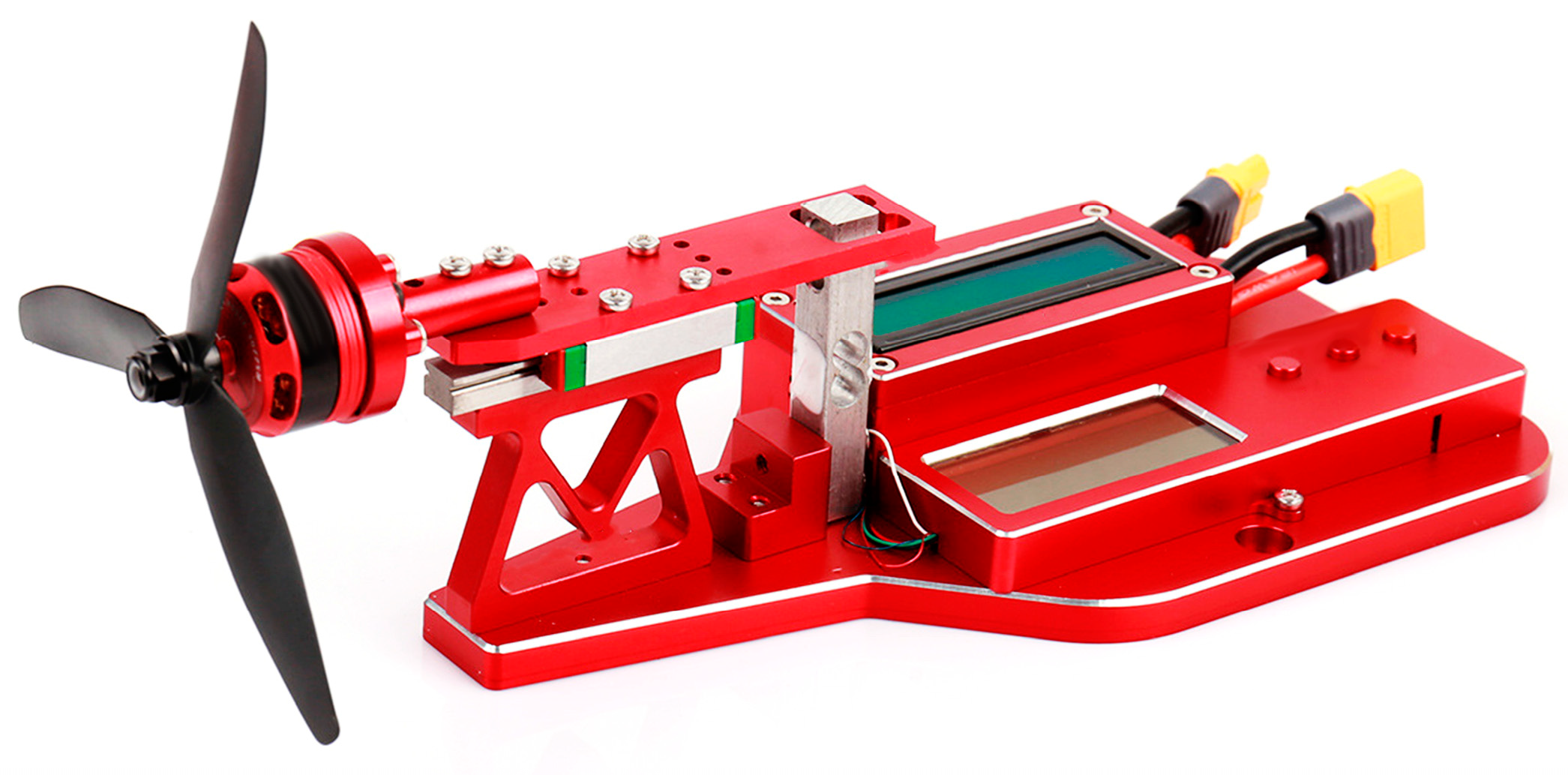
Usually, the relationship between the motor control signal and the thrust can be easily obtained by an experiment on the test bench shown in Figure 3. But the data collected on the ground is not enough to accurately represent the thrust when the UAV is flying since there is freestream come into the propeller. Thus, in this paper, we use a hybrid method to build the model of the propulsion system. We will first build the model of the motor and propeller including the freestream velocity, and then calculate the parameters of the model based on the ground experiment.

3.1. Motor Model Description

For a commonly used brushless direct current (BLDC) motor [47], its model can typically be described as (3) [48].
E = R m I + K ω T e = K I ,
where E is the applied voltage, R m is the stator resistance, I is the current, ω is the motor speed, T e is the output torque of the motor, and K is the back electromotive force coefficient (also known as the KV value). The specific explanation of the symbols is provided in Table 2.

3.2. Propeller Model Description

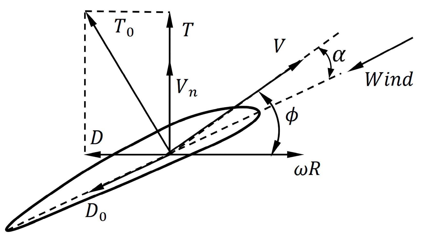
The propeller is modeled using the momentum-blade element theory, which considers the propeller a wing traveling through the air. The thrust or drag generated by the propeller can be described using classical lift and drag formulas. The description of the propeller’s speed and force is shown in Figure 4. The thrust produced by the propeller originates from changes in airspeed within the propeller disk area. Therefore, the airspeed at the propeller blades is not just rotational speed but also includes the airflow speed (induced speed). The induced speed V n is expressed as
V n = V a + V s 2 ,   V s = 2 T ρ A + V a 2 .
where V n is the induced speed at the propeller disk, and A represents the propeller disk area, and T is the thrust.
For modeling a specific propeller, the mechanical model can be simplistically represented as (5) [49].
T 0 = α p C t V 2 D 0 = α p C d V 2
where V is the airspeed at the characteristic radius, C t is the thrust coefficient, and C d is the drag coefficient. These two coefficients are going to be identified through the experimental data. T 0 and D 0 are thrust and drag force in the airflow frame that is fixed with the air speed direction. α p is the angle of attack of the propeller blade relative to the air, expressed as α p = θ p ϕ , where ϕ represents the downwash angle, and its expression is given in (6).
ϕ = tan 1 V n / ω R .
In (6) R is the characteristic radius of the propeller taken as 70% of the standard radius. θ p is the twist angle at the propeller’s characteristic radius, related to the pitch as θ p = tan 1 h m / 2 π R .
By combining (5) and (6), the expressions for the thrust and drag torque of the propeller and propulsion motor are obtained as
cos ϕ sin ϕ sin ϕ cos ϕ T 0 D 0 = T D R ,
where D is the drag torque in the body frame. After rearrangement, we obtain
T = ω R C t V n C d θ tan 1 V n ω R V n 2 + ω R 2 D = V n C t + ω R C d θ tan 1 V n ω R V n 2 + ω R 2 R .
During the experiment, the current, voltage applied to the motor, RPM, and thrust are collected. Then, these data are used to estimate R m , K , C t , C d . We can estimate the required voltage for a given T and V a by solving (3) and (8). In the actual system, we calculate the actual duty cycle based on the target voltage and the actual battery voltage.

4. Fuzzy-Guaranteed Cost Controller Design

In this section, the controller is designed based on the F-GCC technique. The longitudinal model of the UAV dynamics is first rewritten in state-space form. Then, the control objective of airspeed and altitude tracking is expressed based on this model. Lastly, the stability criteria as well as the global optimization are performed by using LMIs tools.

4.1. T–S Fuzzy Model of the Fixed-Wing System

For the controller design purposes, (1) is initially transformed into a state-space equation. This is followed by translation and fuzzification processes, and the final expression is
x ˙ t = f x t , u t ,
where x t = u t w t θ t q t H t T , u t = δ e t T t T represent the state and control input, respectively.
The T–S fuzzy model is a piecewise nonlinear model, which uses a set of local linear models to approximate the target’s nonlinear model. This model divides the input space into multiple fuzzy subspaces, builds a linear model for each fuzzy subspace, and smooths the connections between the subspaces using membership functions finally.
If the control input is divided into i types of sub-inputs, with the membership degree for different input u i represented by h i . Considering disturbances, the corresponding fuzzy model is represented as
x ˙ = i = 1 N h i x t A i x t + B i u t ,
where N represents the number of fuzzy rules, matrix A i and matrix B i are the partial derivatives of f x t , u t respect to x t and u t at each trimmed reference point ( x i , u i ) , known as the Jacobian matrix. A i is referred to as the state matrix, A i = f x | ( x i , u i ) , while B i is the input matrix, B i = f u | ( x i , u i ) . The term h i x t is the weight of each subsystem, satisfying 0 h i x t 1 ,   i = 1 N h i x t = 1 , i 1,2 , , N .

4.2. Controller Structure Design

To achieve the speed and altitude trajectory tracking, x t and u t in (9) must be shifted with x ¯ and u ¯ , where x ¯ t = x t x , u ¯ t = u t u , x and u represent the desired state and trimmed input respect to the given speed and altitude. Following this transformation, the system becomes
x ˙ t = i = 1 N h i x t A i x ¯ t + B i u ¯ t s y s t e m   d y n a m i c + i = 1 N h i x t A i x i * + B i u i * s y s t e m   t r i m ,
In order to obtain ( x i , u i ) , we can solve f x i , u i x ˙ i = 0 indicating that the desired state and control input are found to trim the system, with x i = u i w i θ i q i H T , u i = δ e i T i T . This paper utilizes MATLAB’s Steady State Manager Toolbox to calculate these feedforward values. It should be noticed that we have used H rather than H i , since the other state reference does not depend on it. It is given by the user directly.
Through appropriate preparation and simplification of the model to reduce the UAV’s nonlinear characteristics, the system is expressed as
x ¯ ˙ = i = 1 N h i x t A i x ¯ t + B i u ¯ t ,
that used to design the feedback controller. The time scaler t and the state x of h i will be omitted if no confusion arises.
To achieve tracking of altitude and velocity trajectories, we define the altitude error as H , the airspeed error as V a , and the control error as e 2 × 1 , where e 1 = H . Since V a = u 2 + v 2 , the value of V a during actual flight is primarily influenced by u . To simplify the model, V a u , with e 2 = u . So, the error is defined as (13).
e = H u ¯ = C x ¯ ,
where C = 0 0 0 0 1 1 0 0 0 0 .
The objective of the controller is to stabilize the system and drive the error towards zero.
l i m t e ( t ) = 0 .
The UAV’s state-space equation is augmented by including the integration of altitude and airspeed errors into the state variables, aiming to eliminate errors in steady-state. The time scaler t will be omitted if no confusion arises. The objective is to make p ˙ = e . The final state-space equations of the UAV are as follows,
x ¯ ˙ L = i = 1 N h i x A L i x ¯ + B L i u ¯ e = C L x ¯ L ,
where
x ¯ L = x ¯ p , A L i = A i 5 5 0 5 2 C 2 5 0 2 2 , B L i = B i 0 2 2 .
The controller is designed as
u = i = 1 N h i x u i t r i m + K L i x ¯ L s t a t e   f e e d b a c k .
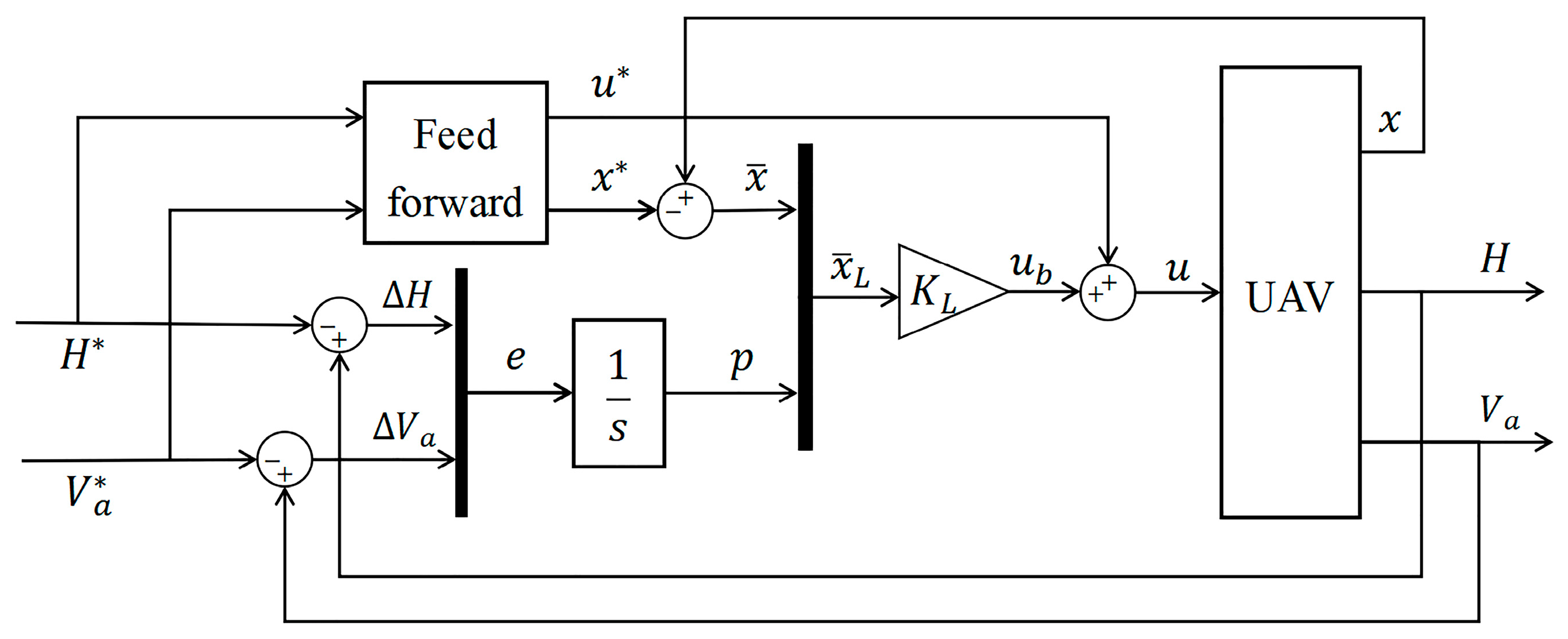
The overall structure of the controller is illustrated in Figure 5. The first part of the controller will trim the UAV for a given trajectory while the last one will make the UAV stable and reject external disturbance. Its specific design details will be discussed in the next part.

4.3. T–S Fuzzy-Based Feedback Controller

Taking the structure of the feedback controller presented in (17), the overall closed-loop system is expressed as
x ¯ ˙ L = i = 1 N h i A L i + j = 1 N h j B L i K L j x ¯ L ,
with
u f b = i = 1 N h i K L i x ¯ L .
The feedback gain K L j is individually tailored for each subsystem to achieve global stabilization and good performance across all fuzzy subsystems. However, designing feedback gain for each fuzzy subsystem will be challenging. The issue is addressed by converting it into a solution of LMIs to determine the feedback gains.

4.4. The LMI Formulation for Guaranteed Cost Control

In control systems, various factors may lead to system instability or performance degradation. The F-GCC technique guarantees robust stability while meeting specified performance criteria. The fundamental theory of the F-GCC technique is as follows.
The fuzzy system is represented as
x ¯ ˙ L = i = 1 N h i A L i + i = 1 N h j B L i K L j x ¯ L e = C L L x ¯ L .
Theorem 1.
For the fuzzy system described in (20), a performance metric is given as
J = 0 x ¯ L T Q x ¯ L + u ¯ T R u ¯ d t ,
where  Q  and  R  are given symmetric positive definite weighting matrices. When there exists a positive definite symmetric matrix P and feedback gains  K L j  satisfying
P i = 1 N h i A L i + j = 1 N h j B L j K L j + i = 1 N h i A L i + j = 1 N h j B L j K L j T P + Q + j = 1 N h i K L i T R j = 1 N h i K L i < 0 ,
The system has a minimal upper bound on performance and achieves asymptotic stability. In this case, (19) represents the optimal control law for the system, where  X = P 1 ,   Y j = K L j X , N denotes the number of subsystems.
Proof. 
Equation (22) can also be written as
P x ¯ ˙ L + x ¯ ˙ L T P + Q + j = 1 N h i K L i T R j = 1 N h i K L i < 0 .
Then, we left multiply by x ¯ L T and right multiply by x ¯ L on (23), we have
x ¯ L T P x ¯ ˙ L + x ¯ ˙ L T P x ¯ L V ˙ t + x ¯ L T Q + ( i = 1 N h i K L i ) T R i = 1 N h i K L i x ¯ L < 0 .
The first part of (24) represents the derivative of a Lyapunov function V ( t ) = x L T P x L . When there exists a positive definite symmetric matrix P making V ˙ t < 0 , the system is global asymmtotically stable. In our case, for the system described by (20), if the previously mentioned P and K L j satisfy (22), meanwhile we take Q and R are positive definite matrix into account, (24) becomes
V ˙ ( t ) < x ¯ L T Q + j = 1 N h i K L i T R j = 1 N h i K L i x ¯ L < 0 .
Integrating both sides of (25) from zero to infinity yields
J 0 x ¯ L T Q x ¯ L + u ¯ T R u ¯ + V ˙ t d t + x ¯ L T 0 P x ¯ L 0 < x ¯ L T 0 P x ¯ L 0 .
Equation (26) indicates that the performance metric J defined earlier for the system has an upper bound, which is x ¯ L T ( 0 ) P x ¯ L ( 0 ) . The initial value x ¯ L ( 0 ) is dependent, to minimize J , P is the only possibility.
But we cannot calculate the optimal gain directly by (22), it needs further process. Let X = P 1 , Y i = K L i X , we can obtain
i = 1 N i = 1 N A L i X + B L i Y j + X A L i T + Y j T B L i T + X Q X + Y i T R Y j < 0 .
To simplify the calculation, we introduce,
i = 1 N j = 1 N h i h j Y i T R Y j i = 1 N j = 1 N h i h j Y i T R Y i 0 ,
then (27) is transformed into a sufficient condition as
i = 1 N i = 1 N A L i X + B L i Y j + X A L i T + Y j T B L i T + X Q X + Y i T R Y i < 0 .
In order to obtain the corresponding LMIs and then implement the optimization process, Q i j is used to denote the reformulated key component of (22) for convenient expression, as shown in
Q i j = A L i X + B L i Y j + X A L i T + Y j T B L i T X Y i T Q 0 0 R X Y i .
By utilizing Schur’s complement lemma, (30) is transformed into LMIs as
A L i X + B L i Y j + X A L i T + Y j T B L i T X Y i T X Q 1 0 Y i 0 R 1 < 0 , i , j N ,
with optimization on
m i n ( T r a c e ( X 1 ) ) .
To make the optimization problem solvable, an intermediary matrix M satisfying M > X 1 > 0 , which is symmetric positive definite, is introduced. Employing Schur’s complement lemma, it is further transformed into an LMI shown as
M I I X > 0 .
Thus, the optimization objective becomes (31)–(33), guaranteeing the minimum value of T r a c e ( X 1 ) . Finally, the feedback gain ( K i ) for each subsystem is obtained by   K i = Y i X 1 .  □

5. Results and Discussion

In this section, we will use the nonlinear model of the UAV to validate the feasibility and effectiveness of the proposed F-GCC technique. Moreover, this paper also employs the common ADRC controller as the comparative candidate to demonstrate the performance advantages of the proposed controller. Numerical experiments are conducted in MATLAB/Simulink. The numerical experiment will evaluate and compare the response of the two candidate controllers concerning:
(1)
Altitude command.
(2)
Lateral motion coupling.
(3)
Parameter errors.
(4)
Gust wind and turbulence.
With these experiments, we can demonstrate the performance of the controller under various conditions.

5.1. Numerical Experiments of the Propulsion Model

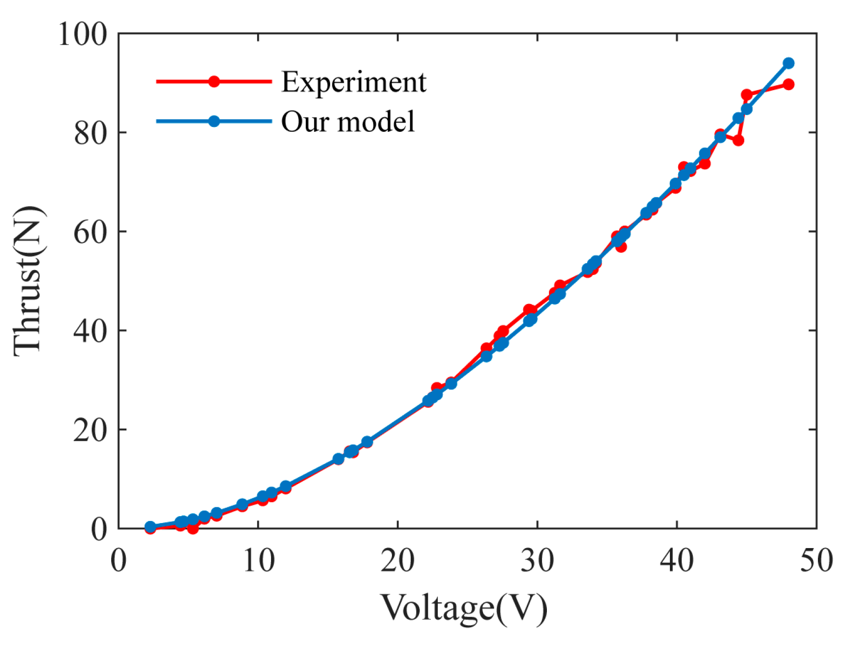
Using the propeller and motor models derived in Section 3, we constructed a simulation model in MATLAB for numerical experiments. The comparison results between the simulation and the experiments are shown in Figure 6.
Figure 6 presents the variation in thrust with voltage. The simulation results of the propulsion system established in the previous sections closely match the actual experiment results. This indicates that the propulsion system constructed in the previous sections is reasonable and accurate. Thus, this model and parameters can be used to build the look-up table for the propulsion system. Applying it in the subsequent controller design reduces the model’s nonlinearity while ensuring its accuracy.
Based on the experimental data, by applying MATLAB and the least squares method for identification, we obtained R m = 0.1537 ,   K = 0.0387 .

5.2. Definition of the Fuzzy Rules

Figure 7 illustrates the block diagram of the fuzzy logic controller, which includes three main stages: fuzzification, fuzzy inference, and defuzzification. We calculate the membership degree based on airspeed ( V a ) and climb rate ( h d ) and obtain the control parameters by weighting the membership degree with feedforward and feedback parameters.
During the design phase, nine operating points for the UAV are defined, based on given V a and h d . The input signal ranges for V a are [20, 30] m/s, and [−2, 2] m/s for h d . The details are as follows.
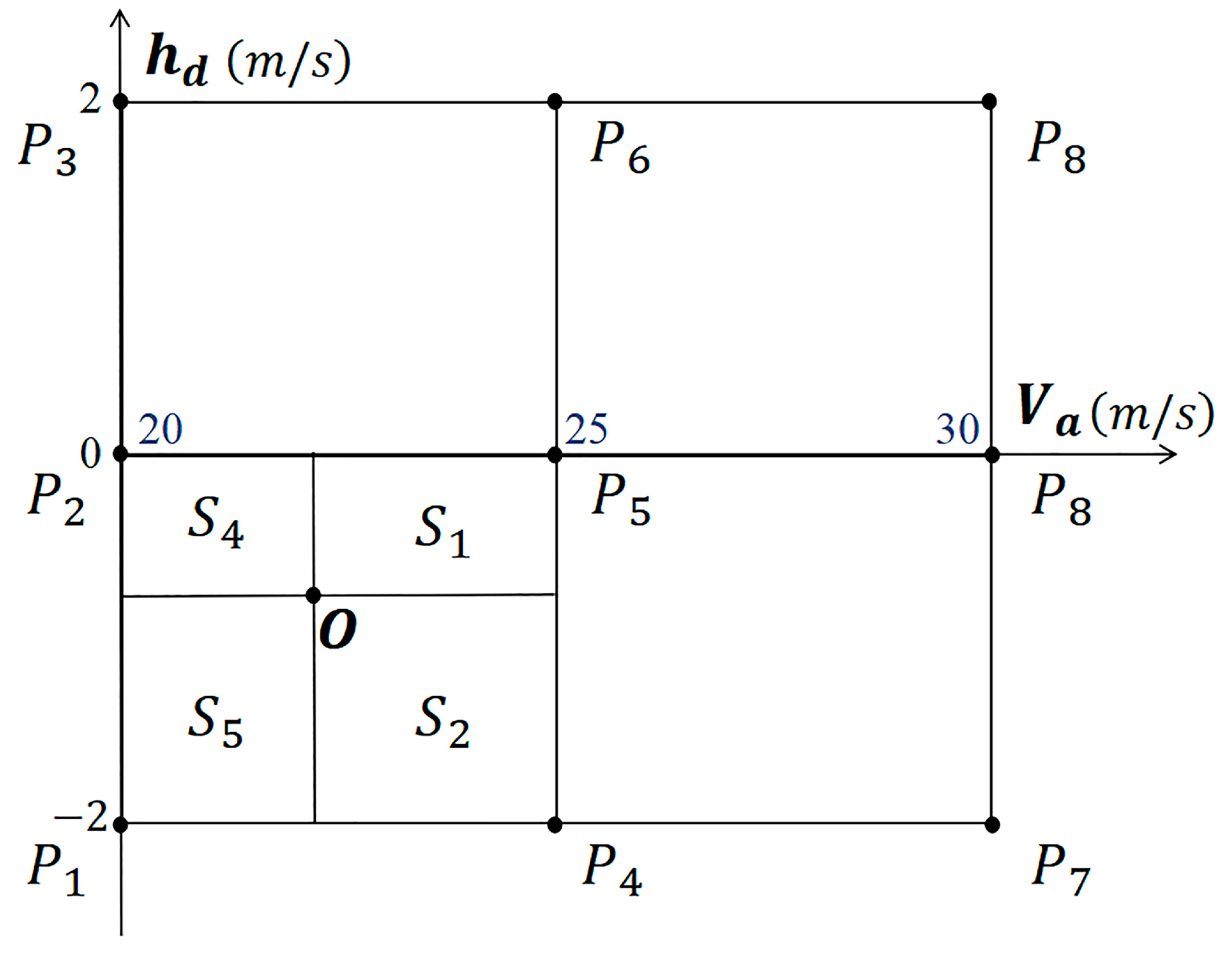
The operating domain, defined by the V a (x-axis) and h d (y-axis), is divided into four operating domains as shown in Figure 8. The membership degrees of the control parameters at the operating points P 1 , P 2 , …, P 9 , are represented by h 1 , h 2 , …, h 9 , respectively. The fuzzy rules are defined as follows:
(1)
The sum of all membership degrees equals 1, i.e., i = 1 9 h i = 1 ;
(2)
Only parameters from adjacent operating points are connected by the membership degrees. For example, as shown in Figure 8, in the domain enclosed by P 1 P 2 P 4 P 5 , only the parameters of P 1 , P 2 , P 4 , and P 5 contribute to the control, rendering h 3 = h 6 = h 7 = h 8 = h 9 = 0 ;
(3)
Given that the area of the domain enclosed by four adjacent operating points is S , when the operating point O V a ,   h d representing the actual state is inside this area, this area can be divided into four sub-domains with two lines crossing the point O and vertical to the axis. The membership degree of each operating point concerning the actual state is defined as the ratio of its diagonal domain area to the total domain area. Taking Figure 8 as an example, the membership degree function is expressed as
f V a , h d = h 1 = S 1 S = 25 V a 0 h d 25 20 0 + 2 h 2 = S 2 S = 25 V a h d + 2 25 20 0 + 2 h 4 = S 4 S = V a 20 0 h d 25 20 0 + 2 h 5 = S 5 S = V a 20 h d + 2 25 20 0 + 2 h 3 = h 6 = h 7 = h 8 = h 9 = 0 20 V a < 25 , 2 h d < 0 .
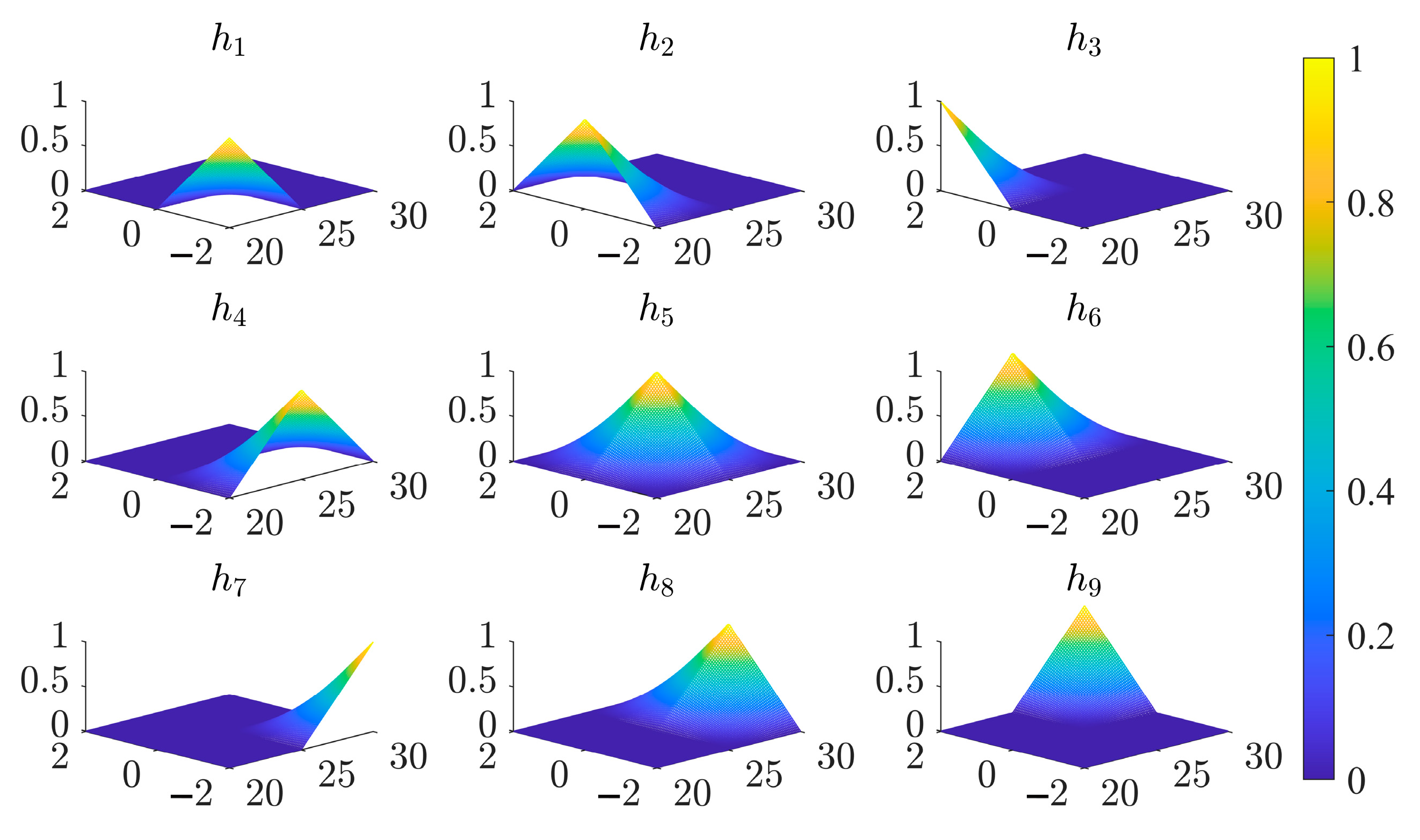
Figure 9 depicts the membership curves for the operational parameters at the nine operating points. The obtained membership degrees, multiplied by the trim values δ e * and T * , yield the feedforward. Combining the membership degrees with the feedback gain ( K i ) , constitutes the feedback control u f . The specific values of K i are provided in Appendix A. Ultimately, the control parameters are input into the UAV controller.

5.3. The Comparative Candidate

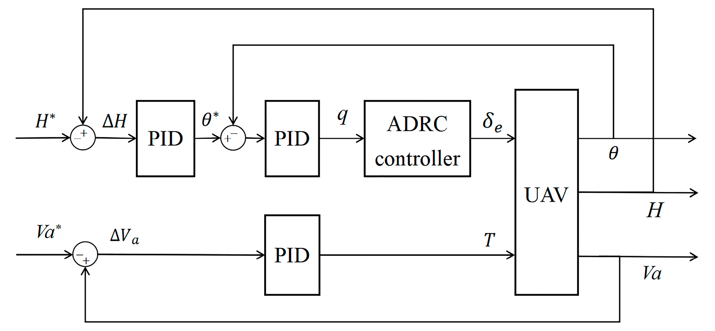
ADRC technology is well known for providing robust disturbance rejection capabilities by an extended state observer. For the longitudinal control of the UAV, the pitch angle loop utilizes the ADRC method to control the pitch angle, as referenced in [28]. The altitude and speed loop utilizes the PID controller. The structure of the longitudinal ADRC controller for the UAV is illustrated in Figure 10. During the parameter tuning process, we adjusted the parameters of PID and ADRC based on the F-GCC response to make the rise times as consistent as possible and then conducted simulation experiments.
The parameters for the ADRC controller refer to the [28], with the outer loop PID parameters k p h = 0.35 , k i h = 0.45 , k d h = 0.1 , and inner loop gains k p θ = 5 , k i θ = 0.2 , k d θ = 0.2 . In Section 5.5, the parameters of the PID attitude loop in the Case 2 experiment are set as follows: k p θ = 5 , k i θ = 3 , k d θ = 5 . The parameters of TD, NLSEF, and ESO are specified in Table 3.

5.4. Parameters of the UAV and the F-GCC Controller

The fundamental parameters of the UAV for the closed-loop numerical experiment are presented in Table 4, and the initial conditions are shown in Table 5. The basic parameters of the F-GCC controller are presented in Table 6. During numerical simulations, the amplitude and rate limits for the primary control device are determined based on actual conditions, as shown in Table 7.

5.5. Experiments of the Altitude Command

These experiments are without parameter errors and disturbances and are divided into the following cases as Table 8.
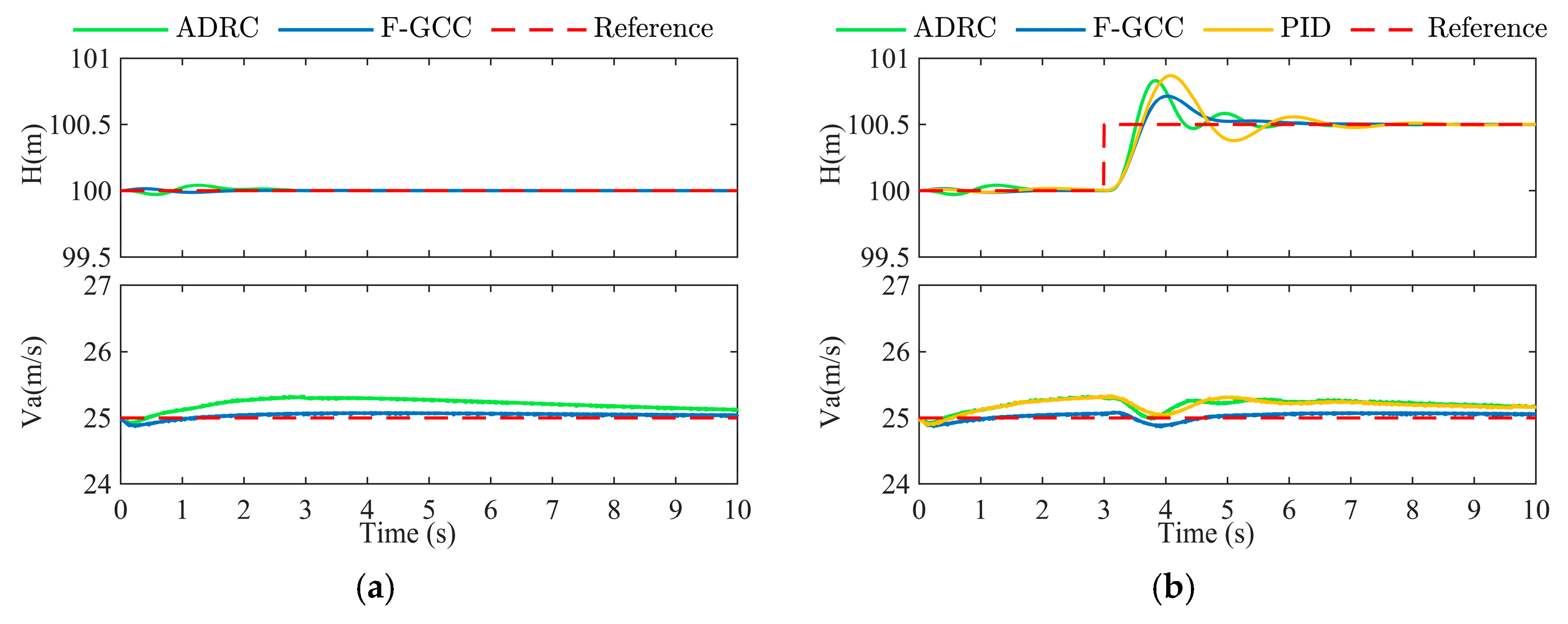
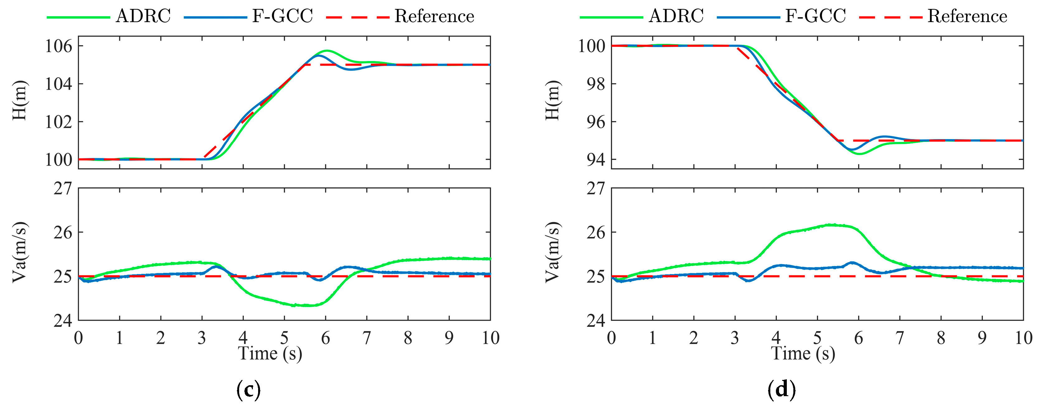
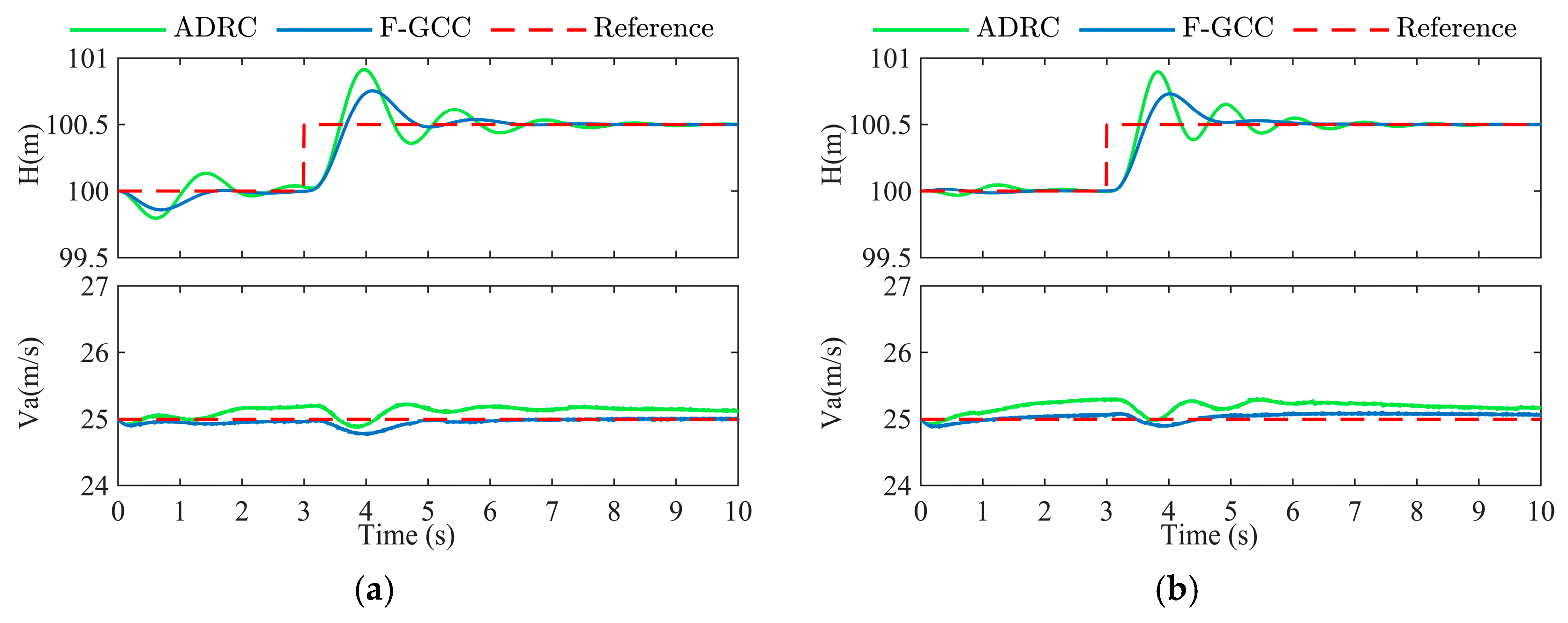
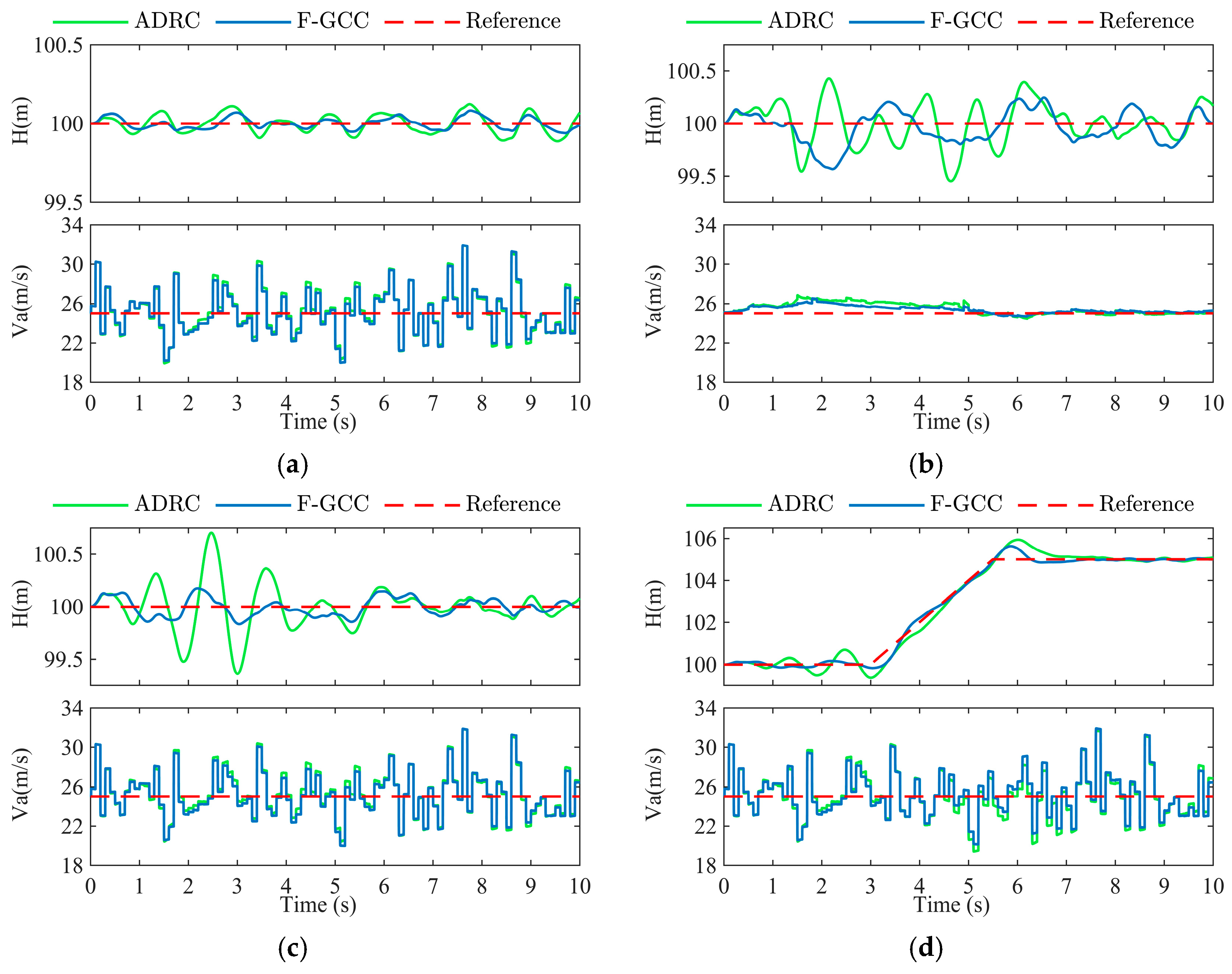
The responses of the F-GCC controller and ADRC controllers to altitude and airspeed commands for these four common trajectories are shown in Figure 11. The root mean square errors (RMSE) of the altitude are presented in Table 9.
Figure 11a shows the altitude and speed variations in the UAV under a constant altitude trajectory command. As the controllers begin to operate, both ADRC and F-GCC controllers exhibit initial altitude errors, but the errors quickly converge.
In the Case 2—step response experiment, in addition to the F-GCC and ADRC-based control methods, we also conducted a comparison experiment using the model-free PID control. Figure 11b shows the response curves of the three controllers, and Table 10 summarizes their performance indicators under the step trajectory. The results indicate that ADRC improves control performance over conventional PID, reducing both overshoot and settling time compared to PID. However, F-GCC achieves smaller overshoots, less oscillation, and faster convergence, offering the best control performance.
The experimental results for the UAV during the climb and descent phases are shown in Figure 11c,d. The F-GCC controller not only precisely tracks the altitude commands but also maintains airspeed stability.
In summary, F-GCC demonstrates superior control performance over ADRC, by smaller overshoot errors and quicker trajectory error elimination.

5.6. Experiment with Unknown Disturbances

In this part, the responses concerning the parameter errors and the wind are conducted. The wind disturbances ( V w _ n , V w _ e , V w _ d ) act on the 6-DOF dynamics model of the UAV are given in the North-East-Down (NED) coordinate system’s N- and D-direction.
First, we verify the case of neglecting the coupling effects of lateral movement. Next, we introduce internal disturbances (by altering C L and C M to simulate model uncertainties and parameter inaccuracies) and external disturbances (simulating wind disturbances with pulse and random disturbances) to evaluate the control performance of F-GCC and ADRC controllers. Specific details of different cases are shown in Table 11.

5.6.1. Lateral Disturbance Experiment (Case 5)

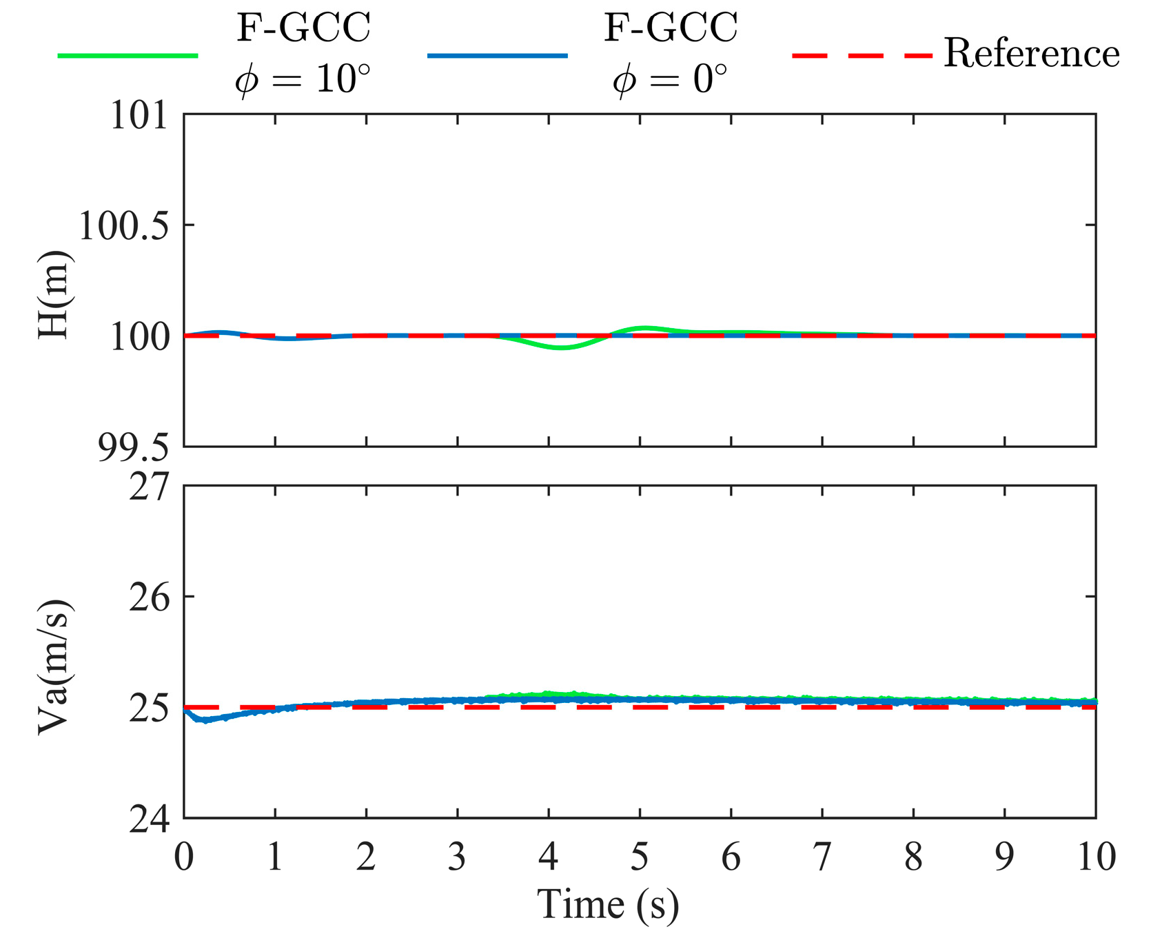
Figure 12 displays the experimental results for Case 5, with the altitude RMSE detailed in Table 12. When the UAV rolls to the right by 10 ° at 3 s, the longitudinal control’s altitude error remains under 0.06 m. Therefore, the coupling effects induced by the lateral motion of the aircraft can be neglected.

5.6.2. Parameter Variation Experiment (Case 6)

In Case 6, we introduce internal disturbances. Figure 13 indicates that the F-GCC controller outperforms in resisting disturbances from internal parameter inaccuracies compared to the ADRC controller.

5.6.3. External Disturbance Experiment (Case 7 and Case 8)

Then, various forms of wind are introduced as disturbances into the UAV’s 6-DOF model. The experimental results are depicted below, with altitude RMSE detailed in Table 13.
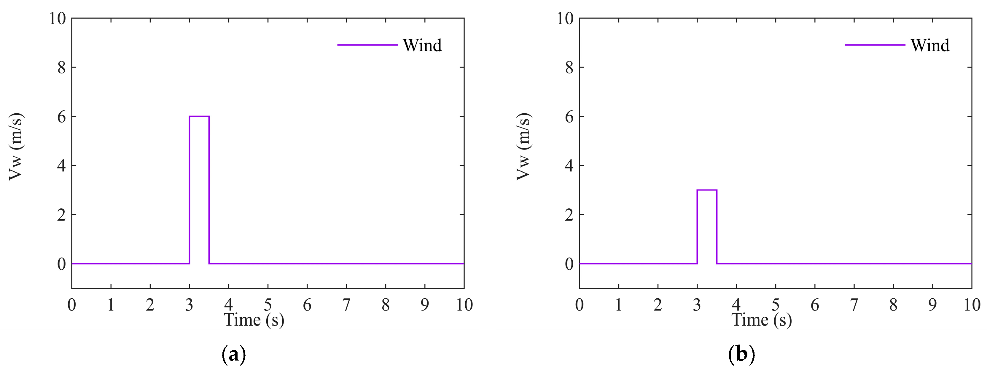
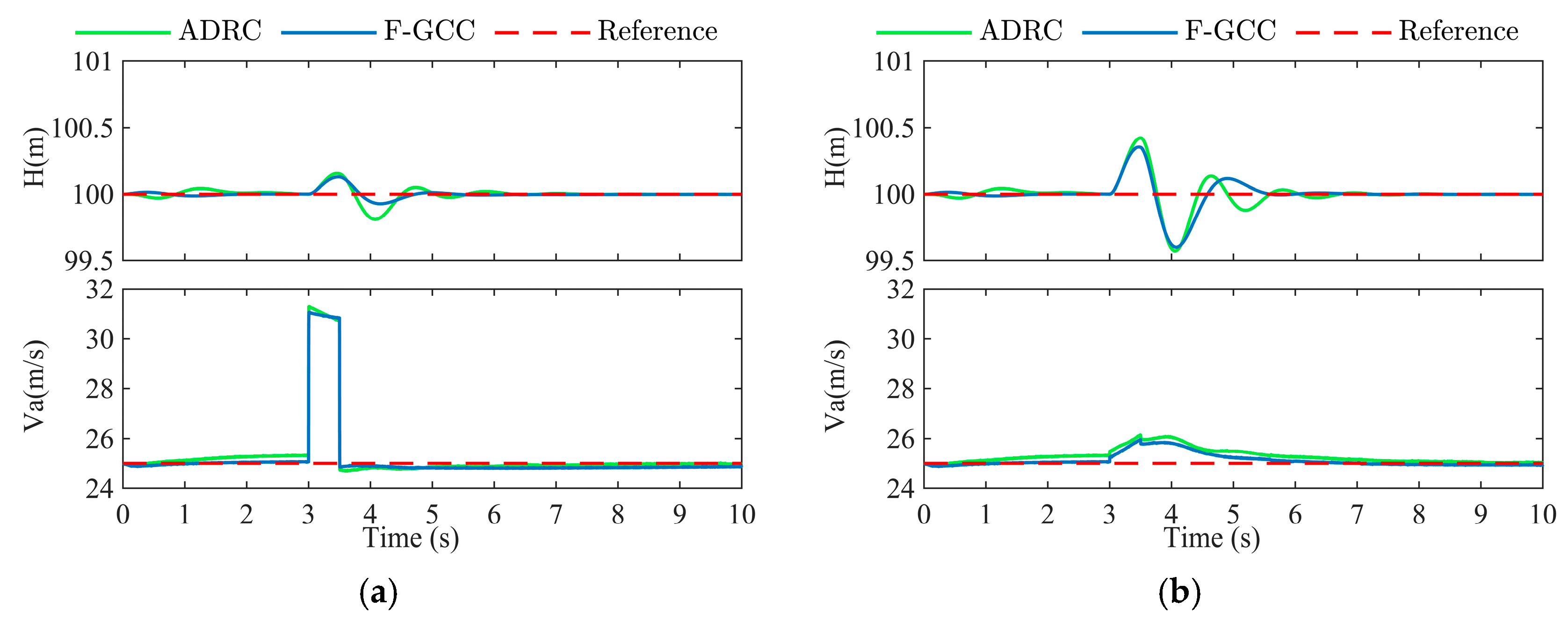
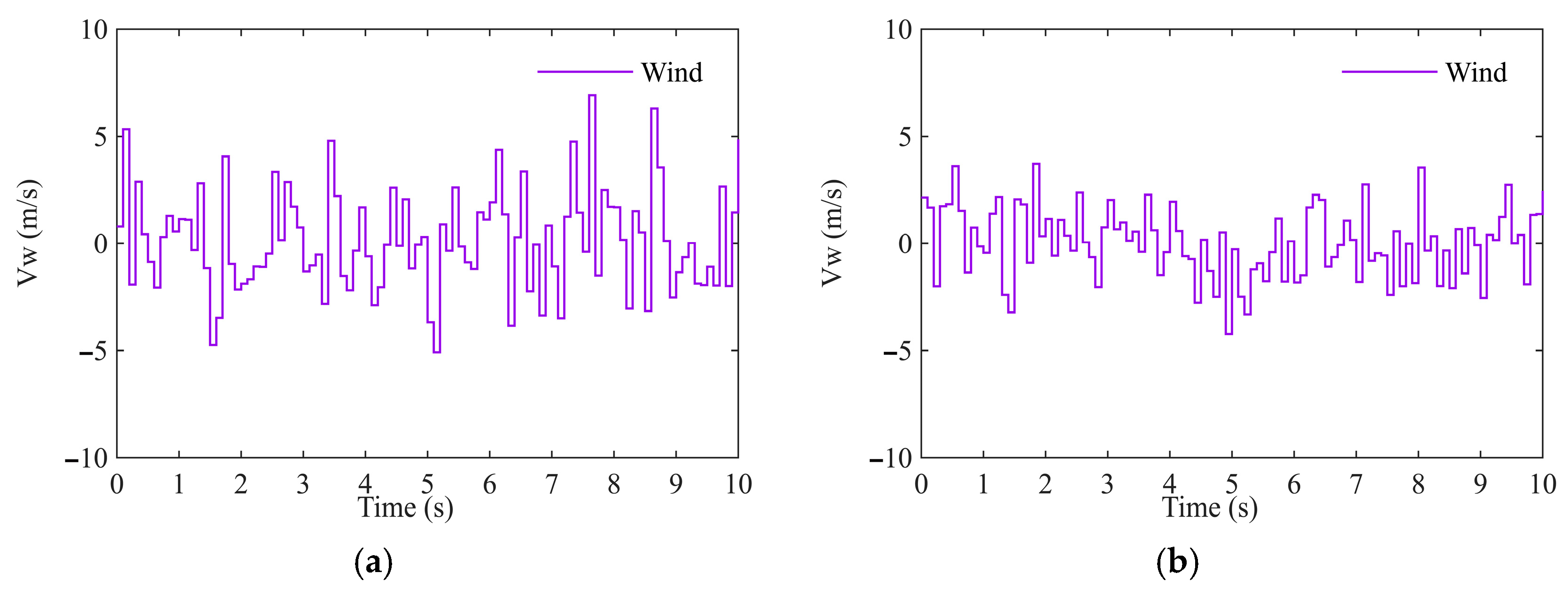
Case 7 introduces horizontal (N-direction) and vertical (D-direction) pulse wind disturbances as Figure 14a,b, with results depicted in Figure 15a,b. Under the added disturbances, the results indicate that both controllers are more sensitive to vertical wind disturbances than horizontal wind disturbances, with F-GCC showing stronger resistance to pulse disturbances.
Case 8.1 and Case 8.2 apply turbulence in the N- and D- directions, as shown in Figure 16a,b, respectively, during level flight. In Case 8.3 and Case 8.4, a mixed disturbance is applied during level and climb flights, adding N-direction and 1/3 D-direction disturbances shown. Figure 17 indicates that the F-GCC controller performs better than the ADRC controller under various turbulence, non-steady-state tracking trajectories more effectively, and maintaining an airspeed with more stability.
The results of various experiments indicate superior control performance and robustness of the F-GCC controller, demonstrating its excellent transient response and disturbance rejection capabilities.

6. Conclusions

This study introduces a novel nonlinear longitudinal controller based on the F-GCC technique for the fixed-wing UAV. The proposed approach integrates the control models of the fixed-wing UAV into a unified form, simplifying control law design and parameter tuning. Compared to the ADRC controller, the longitudinal controller designed using the F-GCC technique demonstrates better transient response and stronger robustness in the presence of disturbances. In the step response, the settling time of F-GCC is 21.9% shorter than that of ADRC, and the overshoot is reduced by 35.2%. During the climbing process, the altitude RMSE of F-GCC is reduced by 45.5% compared to ADRC. The superiority of the proposed approach has been validated through multiple sets of typical numerical experiments. In future work, we plan to conduct real flight experiments to further validate and optimize the proposed control law. Additionally, we aim to extend this method to improve the lateral control law of the UAV, enabling full three-dimensional trajectory tracking.

Author Contributions

Conceptualization, J.L., T.L. and X.L.; methodology, J.L., T.L. and X.L.; software, T.L. and X.L.; validation, X.L.; formal analysis, T.L. and X.L.; investigation, D.W.; resources, Z.P.; data curation, T.L., X.L., D.W. and Z.P.; writing—original draft preparation, X.L.; writing—review and editing, J.L., T.L. and X.L.; visualization, T.L. and X.L.; supervision, J.L. and T.L.; project administration, J.L. and T.L.; funding acquisition, J.L. All authors have read and agreed to the published version of the manuscript.

Funding

This research was funded by the National Natural Science Foundation of China, grant number 62203335.

Data Availability Statement

Data are contained within the article.

Conflicts of Interest

The authors declare no conflicts of interest.

Appendix A

Table A1. The specific values of the feedback gain K i .
Feedback GainValues
K 1 0.6170.482−14.136−1.884−1.294−1.3270.086
−22.5562.719−45.448−7.083−10.765−2.056−2.677
K 2 0.7470.487−14.226−1.916−1.249−1.3280.101
−22.0702.961−49.634−7.985−11.208−2.424−2.685
K 3 0.8270.493−14.313−1.942−1.221−1.3290.111
−21.6893.109−51.591−8.385−11.371−2.507−2.703
K 4 0.0050.411−11.350−1.547−1.220−1.0410.010
−23.360−0.2846.4183.587−8.1220.341−2.761
K 5 0.0240.412−11.369−1.552−1.212−1.0380.012
−23.101−0.2435.9893.414−8.1000.395−2.770
K 6 0.0330.412−11.387−1.557−1.205−1.0340.014
−22.784−0.2516.6923.487−7.9360.561−2.773
K 7 −0.2010.350−9.529−1.265−1.024−0.786−0.017
−23.100−2.05940.73910.083−6.1501.827−2.713
K 8 −0.1800.348−9.510−1.263−1.013−0.784−0.015
−22.788−2.03540.6359.942−6.1061.864−2.709
K 9 −0.1680.347−9.496−1.261−1.006−0.782−0.013
−22.437−2.05541.40610.033−5.9941.965−2.707

References

  1. Van Blyenburgh, P. UAVs: An Overview. Air Space Eur. 1999, 1, 43–47. [Google Scholar] [CrossRef]
  2. Nex, F.; Armenakis, C.; Cramer, M.; Cucci, D.; Gerke, M.; Honkavaara, E.; Kukko, A.; Persello, C.; Skaloud, J. UAV in the Advent of the Twenties: Where We Stand and What Is Next. ISPRS J. Photogramm. Remote Sens. 2022, 184, 215–242. [Google Scholar] [CrossRef]
  3. Eckel, L.; Stütz, P. Hyperspectral Sensor Management for UAS: Performance Analysis of Context-Based System Architectures for Camouflage and UXO Anomaly Detection Workflows. Drones 2024, 8, 529. [Google Scholar] [CrossRef]
  4. Martínez-Carricondo, P.; Agüera-Vega, F.; Carvajal-Ramírez, F.; Mesas-Carrascosa, F.; García-Ferrer, A.; Pérez-Porras, F. Assessment of UAV-Photogrammetric Mapping Accuracy Based on Variation of Ground Control Points. Int. J. Appl. Earth Obs. Geoinf. 2018, 72, 1–10. [Google Scholar] [CrossRef]
  5. Elkhrachy, I. Accuracy Assessment of Low-Cost Unmanned Aerial Vehicle (UAV) Photogrammetry. Alex. Eng. J. 2021, 60, 5579–5590. [Google Scholar] [CrossRef]
  6. Siddiqi, M.A.; Iwendi, C.; Jaroslava, K.; Anumbe, N. Analysis on Security-Related Concerns of Unmanned Aerial Vehicle: Attacks, Limitations, and Recommendations. Math. Biosci. Eng. 2022, 19, 2641–2670. [Google Scholar] [CrossRef]
  7. Yaacoub, J.; Noura, H.; Salman, O.; Chehab, A. Security Analysis of Drones Systems: Attacks, Limitations, and Recommendations. Internet Things 2020, 11, 100218. [Google Scholar] [CrossRef] [PubMed]
  8. Azar, A.T.; Serrano, F.E.; Kamal, N.A.; Koubaa, A. Decoupled Lateral-Longitudinal Dynamic Modeling and Control of Unmanned Aerial Vehicles. In Proceedings of the 2021 IEEE International Conference on Autonomous Robot Systems and Competitions (ICARSC), Santa Maria da Feira, Portugal, 28–29 April 2021; IEEE: Piscataway, NJ, USA, 2021; pp. 117–122. [Google Scholar]
  9. Liu, C.; Chen, W. Disturbance Rejection Flight Control for Small Fixed-Wing Unmanned Aerial Vehicles. J. Guid. Control Dyn. 2016, 39, 2810–2819. [Google Scholar] [CrossRef]
  10. Susanto, T.; Bayu Setiawan, M.; Jayadi, A.; Rossi, F.; Hamdhi, A.; Persada Sembiring, J. Application of Unmanned Aircraft PID Control System for Roll, Pitch and Yaw Stability on Fixed Wings. In Proceedings of the 2021 International Conference on Computer Science, Information Technology, and Electrical Engineering (ICOMITEE), Banyuwangi, Indonesia, 27–28 October 2021; IEEE: Piscataway, NJ, USA, 2021; pp. 186–190. [Google Scholar]
  11. Elsayed, A.; Hafez, A.; Ouda, A.N.; Ahmed, H.E.H.; Abd-Elkader, H.M. Design of Longitudinal Motion Controller of a Small Unmanned Aerial Vehicle. Int. J. Intell. Syst. Appl. 2015, 7, 37–47. [Google Scholar] [CrossRef]
  12. Xu, P.; Wu, Y.; Zuo, J.; Cheng, L. Longitudinal Attitude Control of UAV Based on Fuzzy PID. In Proceedings of the 2018 IEEE CSAA Guidance, Navigation and Control Conference (CGNCC), Xiamen, China, 10–12 August 2018; IEEE: Piscataway, NJ, USA, 2018; pp. 1–5. [Google Scholar]
  13. Wang, S.; Yao, G.; Chen, F. Cascade PID Attitude Control Based on Adaptive Feedforward Compensation for Fixed-Wing UAV. In Proceedings of the 2021 33rd Chinese Control and Decision Conference (CCDC), Kunming, China, 22–24 May 2021; IEEE: Piscataway, NJ, USA, 2021; pp. 5006–5010. [Google Scholar]
  14. Sadeghzadeh, I.; Zhang, Y. Actuator Fault-Tolerant Control Based on Gain-Scheduled PID with Application to Fixed-Wing Unmanned Aerial Vehicle. In Proceedings of the 2013 Conference on Control and Fault-Tolerant Systems (SysTol), Nice, France, 9–11 October 2013; IEEE: Piscataway, NJ, USA, 2013; pp. 342–346. [Google Scholar]
  15. Poksawat, P.; Wang, L.; Mohamed, A. Gain Scheduled Attitude Control of Fixed-Wing UAV with Automatic Controller Tuning. IEEE Trans. Control Syst. Technol. 2018, 26, 1192–1203. [Google Scholar] [CrossRef]
  16. Melo, A.; Andrade, F.; Guedes, I.; Carvalho, G.; Zachi, A.; Pinto, M. Fuzzy Gain-Scheduling PID for UAV Position and Altitude Controllers. Sensors 2022, 22, 2173. [Google Scholar] [CrossRef] [PubMed]
  17. Sankaranarayanan, V.; Mahindrakar, A. Control of a Class of Underactuated Mechanical Systems Using Sliding Modes. IEEE Trans. Robot. 2009, 25, 459–467. [Google Scholar] [CrossRef]
  18. Wang, Q.; Wang, W.; Suzuki, S. UAV Trajectory Tracking under Wind Disturbance Based on Novel Antidisturbance Sliding Mode Control. Aerosp. Sci. Technol. 2024, 149, 109138. [Google Scholar] [CrossRef]
  19. Irfan, S.; Zhao, L.; Ullah, S.; Javaid, U.; Iqbal, J. Differentiator- and Observer-Based Feedback Linearized Advanced Nonlinear Control Strategies for an Unmanned Aerial Vehicle System. Drones 2024, 8, 527. [Google Scholar] [CrossRef]
  20. Lungu, M. Auto-Landing of Fixed Wing Unmanned Aerial Vehicles Using the Backstepping Control. ISA Trans. 2019, 95, 194–210. [Google Scholar] [CrossRef]
  21. Wang, J.; Alattas, K.A.; Bouteraa, Y.; Mofid, O.; Mobayen, S. Adaptive Finite-Time Backstepping Control Tracker for Quadrotor UAV with Model Uncertainty and External Disturbance. Aerosp. Sci. Technol. 2023, 133, 108088. [Google Scholar] [CrossRef]
  22. Lane, S.; Stengel, R. Flight Control Design Using Nonlinear Inverse Dynamics. In Proceedings of the 1986 American Control Conference, Seattle, WA, USA, 18–20 June 1986; IEEE: Piscataway, NJ, USA, 1986; pp. 587–596. [Google Scholar]
  23. Pashilkar, A.; Ismail, S.; Ayyagari, R.; Sundararajan, N. Design of a Nonlinear Dynamic Inversion Controller for Trajectory Following and Maneuvering for Fixed Wing Aircraft. In Proceedings of the 2013 IEEE Symposium on Computational Intelligence for Security and Defense Applications (CISDA), Singapore, 16–19 April 2013; IEEE: Piscataway, NJ, USA, 2013; pp. 64–71. [Google Scholar]
  24. Lungu, M. Auto-Landing of UAVs with Variable Centre of Mass Using the Backstepping and Dynamic Inversion Control. Aerosp. Sci. Technol. 2020, 103, 105912. [Google Scholar] [CrossRef]
  25. Yang, Y.; Zhu, J.; Yuan, X.; Wang, X.; Kuang, M.; Shi, H. Dynamic Characteristics Analysis and Robust Transition Control of Tail-Sitter VTOL UAVs. Aerosp. Sci. Technol. 2024, 145, 108868. [Google Scholar] [CrossRef]
  26. Putro, I.; Duhri, R. Longitudinal Stability Augmentation Control for Turbojet UAV Based on Linear Quadratic Regulator (LQR) Approach. AIP Conf. Proc. 2020, 2226, 020013. [Google Scholar]
  27. Niu, T.; Xiong, H.; Zhao, S. Based on ADRC UAV Longitudinal Pitching Angle Control Research. In Proceedings of the 2016 IEEE Information Technology, Networking, Electronic and Automation Control Conference, Chongqing, China, 20–22 May 2016; IEEE: Piscataway, NJ, USA, 2016; pp. 21–25. [Google Scholar]
  28. Zhu, G.; Qi, J.; Wu, C. Landing Control of Fixed-Wing UAV Based on ADRC. In Proceedings of the 2019 Chinese Control Conference (CCC), Guangzhou, China, 27–30 July 2019; IEEE: Piscataway, NJ, USA, 2019; pp. 8020–8025. [Google Scholar]
  29. Bie, G.; Chen, X. UAV Trajectory Tracking Based on ADRC Control Algorithm. ITM Web Conf. 2022, 47, 02017. [Google Scholar] [CrossRef]
  30. Wang, B.; Yan, Y.; Xiong, X.; Han, Q.; Li, Z. Attitude Control of Small Fixed−Wing UAV Based on Sliding Mode and Linear Active Disturbance Rejection Control. Drones 2024, 8, 318. [Google Scholar] [CrossRef]
  31. Hervas, J.; Kayacan, E.; Reyhanoglu, M.; Tang, H. Sliding Mode Control of Fixed-Wing UAVs in Windy Environments. In Proceedings of the 2014 13th International Conference on Control Automation Robotics & Vision (ICARCV), Singapore, 10–12 December 2014; IEEE: Piscataway, NJ, USA, 2014; pp. 986–991. [Google Scholar]
  32. Lee, H.; Utkin, V. Chattering Suppression Methods in Sliding Mode Control Systems. Annu. Rev. Control 2007, 31, 179–188. [Google Scholar] [CrossRef]
  33. Putro, I.; Sofyan, S.; Andiarti, R. Incremental Control for LAPAN Turbojet UAV Considering Disturbance and Uncertainties. In Proceedings of the 2019 IEEE International Conference on Aerospace Electronics and Remote Sensing Technology (ICARES), Yogyakarta, Indonesia, 17–18 October 2019; IEEE: Piscataway, NJ, USA, 2019; pp. 1–8. [Google Scholar]
  34. Razmjooei, H.; Palli, G.; Abdi, E.; Strano, S.; Terzo, M. Finite-Time Continuous Extended State Observers: Design and Experimental Validation on Electro-Hydraulic Systems. Mechatronics 2022, 85, 102812. [Google Scholar] [CrossRef]
  35. Blanchini, F.; Miani, S.; Rinaldi, F. Guaranteed Cost Control for Multi-Inventory Systems with Uncertain Demand. Automatica 2004, 40, 213–223. [Google Scholar] [CrossRef]
  36. Chang, S.; Peng, T. Adaptive Guaranteed Cost Control of Systems with Uncertain Parameters. IEEE Trans. Autom. Control 1972, 17, 474–483. [Google Scholar] [CrossRef]
  37. Liu, T.; Liu, Z.; Zhu, F. A Nonlinear Robust Speed Controller for Dual Nonidentical Parallel PMSM System. IEEE Trans. Power Electron. 2022, 37, 10190–10199. [Google Scholar] [CrossRef]
  38. Tian, X.; Huang, D.; Qin, N.; Gong, Z.; Wang, Q. Guaranteed Cost Optimal Control of High-Speed Train with Time-Delay in Cruise Phase. Int. J. Control Autom. Syst. 2021, 19, 2971–2983. [Google Scholar] [CrossRef]
  39. Li, S.; Yang, L.; Gao, Z.; Li, K. Optimal Guaranteed Cost Cruise Control for High-Speed Train Movement. IEEE Trans. Intell. Transp. Syst. 2016, 17, 2879–2887. [Google Scholar] [CrossRef]
  40. Takagi, T.; Sugeno, M. Fuzzy Identification of Systems and Its Applications to Modeling and Control. IEEE Trans. Syst. Man Cybern. 1985, SMC-15, 116–132. [Google Scholar] [CrossRef]
  41. Mao, X.; Zhang, H.; Han, D. T-S Fuzzy Control for a Quad-Rotor UAV. In Proceedings of the 2015 34th Chinese Control Conference (CCC), Hangzhou, China, 28–30 July 2015; IEEE: Piscataway, NJ, USA, 2015; pp. 3617–3622. [Google Scholar]
  42. Pedro, J.; Kala, P. Nonlinear Control of Quadrotor UAV Using Takagi-Sugeno Fuzzy Logic Technique. In Proceedings of the 2015 10th Asian Control Conference (ASCC), Kota Kinabalu, Malaysia, 31 May–3 June 2015; IEEE: Piscataway, NJ, USA, 2015; pp. 1–6. [Google Scholar]
  43. Xu, L.; Ye, Y.; Yi, Y.; Zheng, W. DOB Tracking Control Algorithm for Unmanned Aerial Vehicles with T-S Disturbance Modeling. In Proceedings of the 2021 40th Chinese Control Conference (CCC), Shanghai, China, 26–28 July 2021; IEEE: Piscataway, NJ, USA, 2021; pp. 503–508. [Google Scholar]
  44. Boyd, S.; El Ghaoui, L.; Feron, E.; Balakrishnan, V. Linear Matrix Inequalities in System and Control Theory; Society for Industrial and Applied Mathematics, Ed.; SIAM studies in applied mathematics; Society for Industrial and Applied Mathematics (SIAM): Philadelphia, PA, USA, 1994; ISBN 978-0-89871-485-2. [Google Scholar]
  45. Beard, R.; McLain, T. Small Unmanned Aircraft: Theory and Practice; Princeton University Press: Princeton, NJ, USA, 2012; ISBN 978-0-691-14921-9. [Google Scholar]
  46. Jodeh, N.; Blue, P.; Waldron, A. Development of Small Unmanned Aerial Vehicle Research Platform: Modeling and Simulating with Flight Test Validation. In Proceedings of the AIAA Modeling and Simulation Technologies Conference and Exhibit, Keystone, Colorado, 21–24 August 2006; American Institute of Aeronautics and Astronautics: Reston, VA, USA, 2006; p. 6261. [Google Scholar]
  47. Jamnani, J.G. Brushless Direct Current Motor. In Special Electrical Machinery; Desai, J.P., Ed.; Wiley: Hoboken, NJ, USA, 2024; ISBN 978-1-394-19361-5. [Google Scholar]
  48. Chapman, S.J. Electric Machinery Fundamentals, 5th ed.; McGraw-Hill: New York, NY, USA, 2012; ISBN 978-0-07-352954-7. [Google Scholar]
  49. Stevens, B.; Lewis, F.; Johnson, E. Aircraft Control and Simulation: Dynamics, Controls Design, and Autonomous Systems: Dynamics, Controls Design, and Autonomous Systems, 1st ed.; Wiley: Hoboken, NJ, USA, 2015; ISBN 978-1-118-87098-3. [Google Scholar]
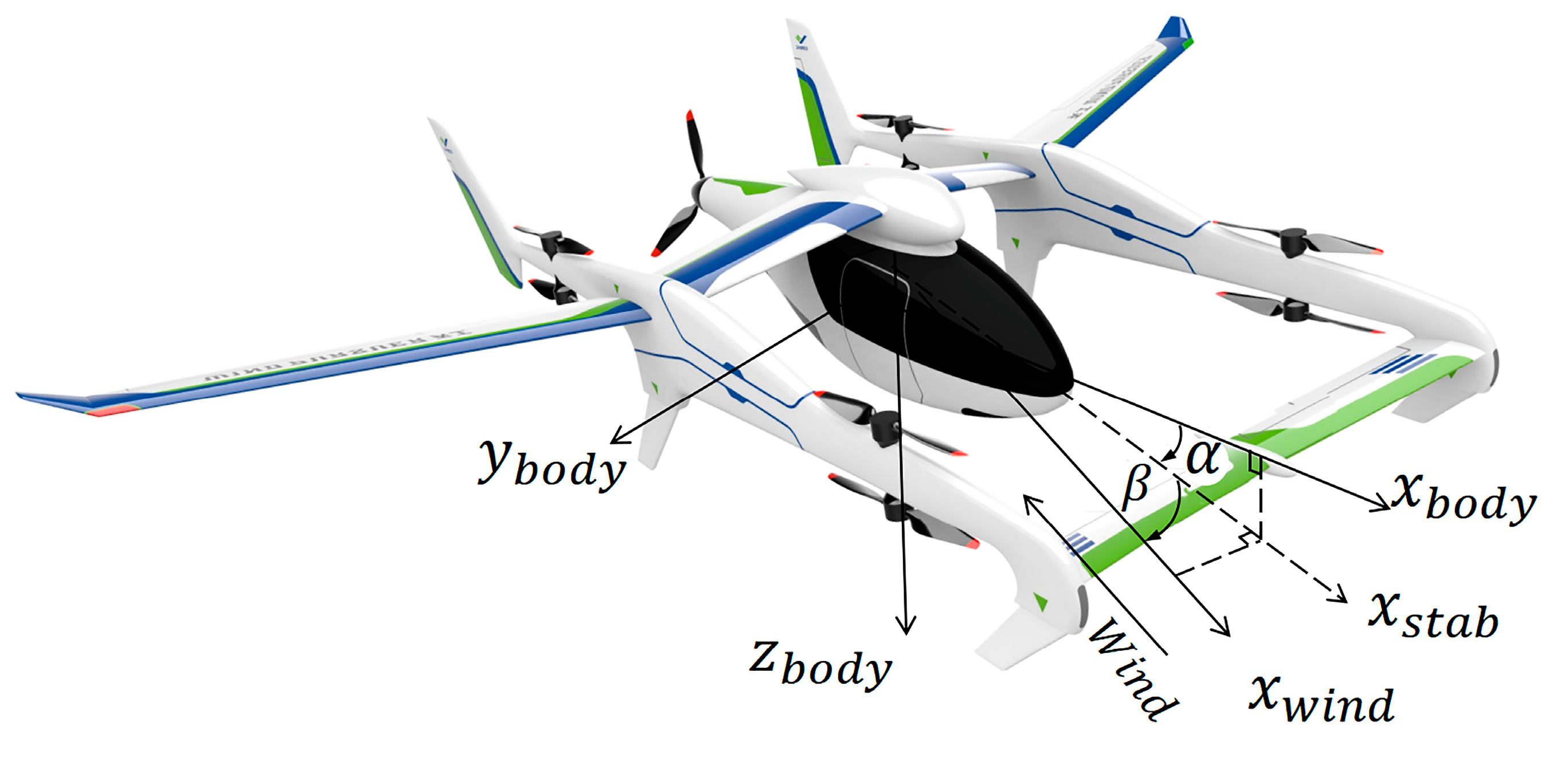
Figure 1. The UAV used in this paper.
Drones 08 00661 g001
Figure 2. The overall structure of the UAV model.
Drones 08 00661 g002
Figure 3. The test bench for the propulsion system.
Drones 08 00661 g003
Figure 4. Description of propeller’s speed and force.
Drones 08 00661 g004
Figure 5. The overall structure of controller.
Drones 08 00661 g005
Figure 6. The propulsion system simulation results.
Drones 08 00661 g006
Figure 7. The structure of the fuzzy logic.
Drones 08 00661 g007
Figure 8. UAV’s operating domains divided by V a and h d .
Drones 08 00661 g008
Figure 9. Membership curves of operational parameters for UAV’s operating points.
Drones 08 00661 g009
Figure 10. The structure of the ADRC controller for the UAV.
Drones 08 00661 g010
Figure 11. The simulation results of the altitude command response: (a) constant altitude trajectory for Case 1; (b) small step trajectory for Case 2; (c) climb trajectory for Case 3; and (d) descent trajectory for Case 4.
Drones 08 00661 g011aDrones 08 00661 g011b
Figure 12. The altitude and airspeed response of F-GCC under lateral coupling in Case 5.
Drones 08 00661 g012
Figure 13. The altitude and airspeed response under parameter variation in Case 6: (a) C L decreases by 30%; (b) C M decreases by 30%.
Drones 08 00661 g013
Figure 14. The gust wind disturbances (in NED coordinate): (a) Case 7.1, 6 m/s in the N-direction; (b) Case 7.2, 3 m/s in the D-direction.
Drones 08 00661 g014
Figure 15. The gust wind disturbances (in NED coordinate): (a) Case 7.1, 6 m/s in the N-direction; (b) Case 7.2, 3 m/s in the D-direction.
Drones 08 00661 g015
Figure 16. The turbulence (in NED coordinate): (a) Case 8.1, the random wind in the N-direction; (b) Case 8.2, the random wind in the D-direction.
Drones 08 00661 g016
Figure 17. The altitude and airspeed response under turbulence: (a) Case 8.1, random wind in the N-direction at level flight; (b) Case 8.2, random wind in the D-direction at level flight; (c) Case 8.3, the combined random wind in the N and D directions during level flight; (d) Case 8.4, the combined random wind in N and D directions during climb flight.
Drones 08 00661 g017
Table 1. Descriptions of symbols used in the UAV’s longitudinal dynamics model.
NameDescriptionNameDescription
u , v , w Components of the UAV velocity C L 0 Zero-lift coefficient
qPitch rate C L α Lift coefficient slope
θ Pitch angle C L q Pitch rate lift coefficient
HFlight altitude C L δ e lift coefficient with respect to elevator deflection
α Angle of attack C D 0 Zero-lift drag coefficient
SWing area C D k Induced drag coefficient
ρ Air density C D q Pitch rate drag coefficient
mMass of the UAV C D δ e Drag coefficient with respect to elevator deflection
cMean Aerodynamic Chord C m 0 pitching moment coefficient when α = 0
V a Airspeed C m α Pitching moment coefficient with respect to angle of attack
TThrust produced by propeller C m q Pitch rate pitching moment coefficient
J Moment of inertia C m δ e Pitching moment coefficient with respect to elevator deflection
Table 2. Descriptions of symbols used in propulsion model.
NameDescriptionNameDescription
EApplied voltage A propeller disk area
R m Stator resistance C t Thrust coefficient
ω Motor speed C d Drag coefficient
R Characteristic radius of the propeller ϕ Downwash angle
KBack electromotive force coefficient h m Propeller pitch
T e Output torque of the motor α p Angle of attack of the propeller relative to the air
V n Induced speed at the propeller disk θ p Twist angle at the propeller’s characteristic radius
Table 3. The parameters of the ADRC controller.
ParametersValues
TD h 1 0.05
r 1 300
NLSEF h 2 0.15
r 2 300
c0.1
ESO δ 0.05
β 01 50
β 02 500
β 03 500
a 01 0.5
a 03 0.25
b−100
Table 4. The basic parameters and dimensionless aerodynamic parameters of the UAV.
ParametersValuesUnitsParametersValues
m30kg C L δ e 0.548
S1.4m2 C D 0 0.035
c0.346m C D k 0.028
b4.460m C D q −1.585
J y 12.024kg·m2 C D δ e 0
ρ 1.225kg/m2 C m 0 −0.296
C L 0 0.5None C m α −4.278
C L α 6None C m q −11.24
C L q 43.4None C m δ e −1.484
Table 5. The initial conditions for the closed-loop simulation.
StatesValuesUnits
h ( 0 ) 100m
V a ( 0 ) 25m/s
h d ( 0 ) 0m/s
Table 6. The parameters of the F-GCC controller.
ParametersValues
Q d i a g   ( 0.1 ,   0.1 ,   0.1 ,   0.1 ,   0.1 ,   3 ,   0.1 )
R d i a g   ( 0.3 ,   0.1 )
Table 7. The amplitude and rate limits for the primary control device.
Control InputAmplitude LimitRate Limit
ValuesUnitsValuesUnits
δ e [−30, 30]Deg±90Deg/s
T[0, 80]NNone
Table 8. The four cases without parameter errors and disturbances.
CasesDescription
Case 1Constant altitude trajectory—The UAV maintains a flight altitude of 100 m.
Case 2Small step trajectory—The UAV undergoes a 0.5 m upward step change in altitude.
Case 3Climb trajectory—The UAV ascends from 100 m to 105 m with a climb rate of 2 m/s.
Case 4Descent trajectory—The UAV descends from 100 m to 95 m with a descent rate of −2 m/s.
Table 9. The RMSEs of altitude for the four cases (×10−2 m).
ControllerCase 1Case 2Case 3Case 4
ADRC1.06510.58024.71024.090
F-GCC0.39810.53014.61014.860
Table 10. Step response performance of Case 2.
ControllerRise TimeSettling Time
( = 0.05 )
OvershootSteady-State
System Response
PID0.6084.07774.26%100.502
ADRC0.5183.26866.600%100.500
F-GCC0.6372.55043.120%100.500
Table 11. The cases with parameter errors and disturbances.
CasesDescription
Case 5Lateral control coupling—During level flight at constant altitude, the UAV executes a 10°
right roll at the third second, maintains the roll for 2 s, and then returns to level.
Case 6Inaccurate aerodynamic parameters.
Case 6.1 A step ascent experiment when the lift coefficient C L decreases by 30%, equating to 0.7 times the normal lift coefficient.
Case 6.2 A step ascent experiment when the pitch moment coefficient C M decreases by 30%, corresponding to 0.7 times its usual value.
Case 7Gust wind.
Case 7.1 A pulse with an amplitude of 6 m/s and a duration of 0.5 s is applied during level flight, in the N-direction (in NED coordinate).
Case 7.2 A pulse with an amplitude of 3 m/s and a duration of 0.5 s is applied during level flight, in the D-direction (in NED coordinate).
Case 8Turbulence.
Case 8.1 Random disturbances in the range of [−5.078, 6.914] m/s are applied in the N-direction at
level flight.
Case 8.2 Random disturbances in the range of [−4.235, 3.711] m/s are applied in the D-direction at
level flight.
Case 8.3 During level flight, the combined random wind disturbances are applied in the N- and D-directions, with the N-direction in the range of [−5.078, 6.914] m/s and the D-direction in the range of [−1.412, 1.237] m/s.
Case 8.4 During climb flight, the combined random wind disturbances are applied in N- and D-directions, with the N-direction in the range of [−5.078, 6.914] m/s and the D-direction in the range of [−1.4117, 1.237] m/s.
Table 12. The RMSEs of altitude for Case 5 (×10−2 m).
StatesCase 5
ϕ = 0 ° 0.398
ϕ = 1 0 1.609
Table 13. The RMSEs of altitude for cases with wind disturbances (×10−2 m).
ControllerCase 6.1Case 6.2Case 7.1Case 7.2Case 8.1Case 8.2Case 8.3Case 8.4
ADRC13.52011.6204.56910.6305.79120.15021.20033.230
F-GCC11.36010.6402.88410.2803.38715.9208.47018.100
Disclaimer/Publisher’s Note: The statements, opinions and data contained in all publications are solely those of the individual author(s) and contributor(s) and not of MDPI and/or the editor(s). MDPI and/or the editor(s) disclaim responsibility for any injury to people or property resulting from any ideas, methods, instructions or products referred to in the content.