Abstract
With the proliferation of Unmanned Aerial Vehicle (UAV) technology, the demand for effective collision avoidance technology has intensified. The DAIDALUS algorithm, devised by NASA Langley Research Center under the Detect-and-Avoid (DAA) framework, provides conflict prevention bands for remotely piloted UAVs navigating in intricate airspace. The algorithm computes the bands in two distinct phases: Conflict and Recovery. The formal model for both phases has been established and implemented through iterative programming approaches. However, the mathematical model remains incomplete. Therefore, based on the model, this paper proposes the mathematical model for the two phases of the horizontal track conflict prevention algorithm. Firstly, Cauchy’s inequality is proposed to formulate the model that addresses trajectory conflicts considering the UAV non-instantaneous maneuvering dynamics model, and then a prudent maneuvering strategy is designed to optimize the model for the recovery phase. Finally, the execution procedure of the algorithm within the two-stage mathematical model is also detailed. The results demonstrate that the proposed model achieves a higher precision in the preventive bands, implements an effective collision avoidance strategy, and consistently aligns with the DAIDALUS model while offering a larger buffer time or distance. This work theoretically validates the formal model of the DAIDLAUS algorithm and provides insights for further refinement.
1. Introduction
Embodying the attributes of a lower cost and convenient operation [1], Unmanned Aerial Vehicles (UAVs) are progressively supplanting manned aircraft in executing high-risk tasks and are pervasively employed in numerous industries, including agriculture, transportation, remote sensing, and detection [2,3]. Due to technical constraints and safety concerns, civil UAVs are restricted to dedicated airspace [4], which significantly limits airspace utilization. As UAV flight density rises, integrating UAVs with manned aircraft in shared aerial domains has emerged as a pressing trend [5,6,7]. The European Union and other international organizations have proposed the concept of Unmanned Aerial System Traffic Management (U-space), also known as Unmanned Aircraft System Traffic Management (UTM) airspace for drones [8]. This concept aims to support safe and efficient UAV operations in low-altitude airspace through digitalized and intelligent management services, which include air traffic management, communication, surveillance, and more [9]. The introduction of U-space offers new solutions for combining UAVs and manned aircraft operations. However, this integration also underscores the urgency for effective UAV collision avoidance technology.
UAV collision avoidance technology comprises three fundamental components: state sensing, conflict detection, and conflict resolution [10]. Central to UAV collision avoidance is conflict resolution, where the geometric method predominates due to its efficient computation and straightforward implementation, becoming the prevalent choice in current UAV collision avoidance algorithms [11]. This method encompasses techniques like the closest point of approach (CPA) [12], the collision cone method (CO) [13], and the velocity obstacle method (VO) [14], with the velocity obstacle method particularly appealing for its commendable real-time and rapid-solving performance akin to the collision cone method, and incorporation of flight time considerations, attracting substantial research attention [15]. Van den Berg and colleagues [16] proposed the concept of the complementary velocity obstacle method, effectively addressing real-time, collision-free motion planning for multi-agent systems operating in a dense environment. To accurately simulate real-world flight scenarios, the application scope of the velocity obstacle method has progressively broadened from dual-aircraft to multi-aircraft collision avoidance. Tan et al. [17] developed the velocity obstacle pyramid method for 3D multi-obstacle avoidance, enhancing UAV navigation in dynamic and static environments. Zhang et al. [18] introduced the collision pool concept, identifying risky UAV pairs for pooling and applying the velocity obstacle method to calculate collision probabilities for each pair, improving multi-aircraft collision avoidance efficiency. With diversifying UAV collision avoidance needs, scholars have integrated other optimization algorithms with the velocity obstacle method. Zhang et al. [19] employed the velocity obstacle method to expand the boundary of the Rapidly exploring Random Tree (RRT) method and eliminate the unavailable branches, significantly boosting the local search efficiency of fixed-wing UAVs and planning an effective and smooth flight path online. He and colleagues [20] combined Distributed Model Predictive Control (DMPC) with the method and designed a control strategy for UAV swarms to track targets while avoiding obstacles, which optimizes group formation and individual tracking.
As the velocity obstacle method evolved, NASA Langley Research Center devised an algorithm that enhanced UAV capabilities in detection, identification, and collision avoidance within the Detect-and-Avoid (DAA) framework: Detect and Avoid Alerting Logic for Unmanned Systems (DAIDALUS) [21]. This algorithm combines the state information of the two aircraft and the geometry of their encounter scenario. After calculations, at a specified sampling moment, a conflict preventive band for the ownship will be determined. This band provides remote pilots with suggested and avoidable maneuvering ranges for horizontal track, horizontal ground speed, and vertical speed to guide the ownship to achieve collision avoidance in real-time, autonomously or collaboratively. Assuming instant UAV maneuverability, a mathematical model was established that transforms physical obstacles into velocity obstacles and delineates safety and collision zones based on the relative velocity tangents to the protected zone, which adheres to the principles of the velocity obstacle methodology [22]. However, for non-instant motion, only a conceptual model of the DAIDALUS algorithm has been formulated, combining a maneuvering dynamics model of large fixed-wing UAVs and iteratively computing maneuvering ranges in conflict to create the conflict prevention bands.
With the flourishing of machine learning, this technology has spurred engagement in DAIDALUS among researchers, leading to diverse DAA algorithms being analyzed through Deep Neural Networks (DNNs) [23]. Park et al. [24] derived the Proximal Policy Optimization (PPO) strategy network’s initial weights from supervised learning. Furthermore, Young Ryu and colleagues [25] simulated DAIDALUS’s behaviors using DNNs, offering a notable advantage in preventing losses of the well-clear zone in two intruder scenarios.
Clearly, the DAIDALUS algorithm has achieved significant advancements in UAV collision prevention and has been widely recognized as an efficient solution within the DAA framework. However, to streamline engineering integration, the algorithm adopts an iterative method to calculate the prevention bands during both conflict and recovery phases, complemented by the Bisection method for searching the optimal target value in the recovery phase. Although its safety and effectiveness have been validated by extensive flight tests, the mathematical model remains unformulated. Thus, this paper aims to propose the mathematical model for the horizontal track conflict prevention algorithm under the DAA framework, validating the formal model and establishing a theoretical basis for further development. Furthermore, in this model a conservative and computationally efficient algorithm is designed for the previous recovery phase, characterized by a substantial search count and high computational demands.
The key contributions and innovative aspects are summarized as follows:
- (1)
- For the scenario of the two aircraft encounters, Cauchy’s inequality, effective in solving tangent problems for nonlinear functions, is introduced to address the crucial geometrical challenge of determining the track conflict boundary under horizontal conflict. Additionally, the boundary equation of the well-clear zone is leveraged to derive the new boundary from vertical conflicts, offering a comprehensive approach.
- (2)
- A new maneuvering strategy, designed specifically for the recovery phase, directly adopts the target value as the resolution path, contrasting with the original model that searches for a faster resolution path near the target value, simplifying computations while ensuring safety.
- (3)
- A detailed algorithm for the proposed model is presented, and simulations are conducted to verify its correctness and effectiveness.
The next sections of this paper are organized as follows. The second part introduces the well-clear protected zone model and the formal model of the DAIDALUS algorithm. The third part establishes the mathematical model of the horizontal track conflict prevention algorithm under the non-instantaneous maneuver. The fourth part details the algorithm design flow for the proposed model. The fifth part outlines test scenarios for simulation comparisons and illustrates the results. Finally, the sixth part summarizes this paper.
2. The Formal Model of the DAIDALUS Conflict Prevention Algorithm
In this paper, we refer to the two aircraft as the ownship and the intruder. For convenience, the following formulas and analysis are based on a relative coordinate system, in which the intruder serves as the origin and remains static, while the ownship moves relative to the intruder [22]. In the airspace system, flight safety necessitates specifying separation criteria between the two aircraft—DTHR, the minimum horizontal separation threshold, and ZTHR, the minimum vertical separation threshold—forming a protective cylinder around the intruder with a radius of DTHR and a half-height of ZTHR, called the protected zone. At a sampling moment, the ownship’s position is given as and its velocity as ; the intruder’s position is and its velocity is . The position and velocity of the two aircraft can then be expressed as and . The two-dimensional vectors are indicated in bold as and . However, the variables of time and distance play a pivotal role in influencing flight safety for both aircraft. The following definitions have been assumed for analysis.
The time of the horizontal closest point of approach is defined as
The distance at the time of the closest point of approach is denoted as
The modified tau, the good approximation of , is as follows
The time to co-altitude is defined as follows
These definitions extend the protection zone temporally and spatially, forming a well-clear protection zone, whose defining constraint is provided as follows. TTHR and TCOA represent the thresholds for the time variables and , respectively. A variable falling below its corresponding threshold indicates a potential risk of a well-clear violation for the two aircraft. When both separation thresholds, TTHR and TCOA, are set to 0, the zone degrades to a basic protection zone. The well-clear zone only applies when both aircraft are in uniform linear motion and without acceleration, which serves as the DAIDALUS algorithm’s protected-area model. The specific values chosen for the thresholds are TTHR = 35 s, TCOA = 0 s, DTHR = 0.66 nm, and ZTHR = 450 ft, which were obtained from the DAIDALUS algorithm and used to maintain consistency with it [26].
From Constraint (5), conflict arises when the predicted horizontal and vertical distances between aircraft are both less than the well-clear thresholds, requiring escape maneuvers. In this paper, we concentrate on adjusting the ownship’s track (left or right turn) at a constant speed to safely separate aircraft. This maneuver is more flexible than changing its horizontal ground speed, which can effectively prevent head-on collisions.
The fundamental steps in the DAIDALUS algorithm include predicting the aircraft’s flight states and detecting conflicts of the states at a discrete sampling moment. Specifically, the ownship is predicted to maneuver from its current position to a certain position, with a turning radius R to the left or right at a constant speed. Constraint (5) is then employed to ascertain the well-clear violation status between the two aircraft. Within the prediction time T, the well-clear conflict status of the two aircraft is detected by evaluating the times of entry and exit of the ownship into and out of the well-clear zone, assuming a uniform straight-line flight from the designated position by both the ownship and the intruder, wherein the prediction accounts for both turning and straight-line maneuvers for the ownship. This process relies on a UAV horizontal maneuvering model, with the following assumptions:
- (1)
- The ownship performs a uniform turn with a fixed rate, resulting in a constant turn radius.
- (2)
- During time T, both aircraft maintain a constant-speed straight-line flight for conflict assessment, under conditions conducive to the formation of the well-clear area.
- (3)
- As the ownship maneuvers following instructions from the remote pilot, the intruder remains on its original flight plan, without any deliberate maneuvering or active changes to its direction [27].
Based on the assumptions above, the DAIDALUS algorithm calculates the prevention bands to assist remote pilots in instructing the ownship for real-time collision avoidance. These bands include maneuvers in the horizontal track that will result in well-clear violations with one or more traffic aircraft within a given lookahead time. These bands are calculated and displayed in real-time on the control panels at ground control stations for remote pilots to judge, reference, and execute maneuvers.
To assess conflict severity, the DAA system classifies alarms, including NEAR, MID, and FAR alerts, according to conflict levels [27]. The highest level, triggered by well-clear violations or conflicts occurring within the , uniquely initiates maneuvers, with an emphasis on NEAR alerts. Thus, only the most urgent NEAR alerts are studied subsequently, specifically those with an set at 25 s. These alerts correspond to three types of preventive bands, where the NONE alert level and its corresponding prevention bands, along with the RECOVERY prevention bands activated during the recovery phase, indicate non-conflict states and provide guidance for track mitigation.
Based on the two aircraft’s positions in relation to the well-clear zone, the DAIDALUS algorithm computes the conflict prevention band in two phases: the conflict maneuver phase and the recovery maneuver phase. The bands are output for collision avoidance guidance in each phase.
In the conflict maneuver phase, the two aircraft with impending or existing violations into the well-clear zone are considered. An iterative discretization of the ownship’s turning prediction identifies conflicting track intervals using a fixed angular increment. Upon detection of a three-dimensional violation, if both aircraft are determined to be in violation at a certain iteration, the continuity of this violation state dictates that all subsequent iterations inherit this state, and the current and all subsequent turn angles are immediately categorized into the highest NEAR-level prevention bands, ensuring comprehensive coverage of potential violations. However, if no immediate violation is triggered at that iteration, future straight-line maneuvers originating from that angle at time T are predicted. Based on assumption (2), if the entry time into the well-clear area precedes the departure time, a near-term NEAR-level conflict is identified, assigning the angle to the corresponding bands. This process generates full track intervals [0, 360°] with associated levels, forming conflict prevention bands. NONE-ranked bands offer clear track guidance for pilots.
During the recovery phase, both aircraft enter the cylindrical protection zone, saturating the conflict prevention bands. Based on the iterative method framework, the search incorporating the dichotomy idea aims to identify a maneuver to promptly restore the clearance status. Initial search bounds are [180, 180]. Only the starting endpoint of the search interval is dynamically adjusted through half expansion or reduction, guided by the dichotomy method, to target the earliest violation-free maneuver. The search halts upon error threshold attainment. Concurrently, prediction intervals [B, T] adapt synchronously. At each iteration, the algorithm detects violation and conflict states based on updated intervals and predictive time periods, forms prevention bands, and checks for saturation. If the bands are unsaturated, the interval expands in half to seek optimality; if saturated, the interval halves until desaturation occurs and the search error falls below the threshold, ultimately outputting RECOVERY-ranked bands. If the unsaturated bands cannot be achieved, the protected zone shrinks horizontally and vertically by a factor, and detection continues to form multilayer concentric cylinders. This guarantees a fast conflict-free maneuver within error bounds, albeit at the cost of shorter time or distance margins, increased flight risks, and intensive computations.
As mentioned above, the DAIDALUS algorithm undergoes formal iterative modeling in both phases, meeting engineering application needs but lacking a detailed mathematical model. Moreover, the recovery phase’s maneuvering strategy entails flight risks and high computation costs. Therefore, this paper next analyzes and proposes the mathematical model for the conflict prevention algorithm, grounded in the existing formal model and framework.
3. Mathematical Model of the Horizontal Track Conflict Prevention Algorithm
Based on UAV dynamic maneuver models, the mathematical model for conflict prevention algorithms is divided into two categories: instantaneous maneuver and non-instantaneous maneuver.
3.1. Mathematical Model Under Instantaneous Maneuver
Ideally, the instantaneous maneuver implies that the UAV can complete the maneuver immediately, invalidating assumption (1). In this case, only the conflict phase calculation is focused on, rendering the recovery phase calculation unnecessary. In [23], detailed steps were outlined to determine the track conflict boundaries under horizontal and vertical conflicts, and a mathematical model for the conflict prevention algorithm was also constructed specifically for the instantaneous maneuver.
3.1.1. Calculation of Track Boundary Angles
Figure 1a depicts the ownship in the relative coordinate system, which is maneuvering instantaneously by maintaining speed but changing direction. In this coordinate system, the intruder remains static while the ownship moves at relative velocities. The circular area with a radius of DTHR represents the horizontal projection of the protected zone, forming part of the expanded area constituting the projection of the well-clear protected zone. The instantaneous maneuver enables the distances of the ownship to travel in a straight line; the different relative velocities can be OE, OB, and OC during the projection time T. The ownship’s direction range in the MN circular arc of the prevention band represents the unsafe track range, i.e., from to , whereas safe tracks lie outside this arc, which necessitates deviation from the MN band during constant-speed direction changes.
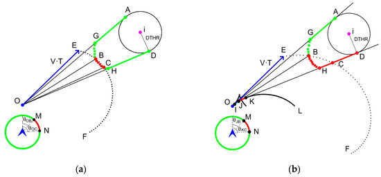
Figure 1.
Sketch map of the mathematical model for calculating the prevention bands under instantaneous and non-instantaneous horizontal maneuvers within the well-clear zone in the relative coordinate system. (a) Instantaneous maneuver scenarios. (b) Proposed non-instantaneous maneuver scenarios.
According to DAA threshold parameters, in Figure 1a, the ownship’s velocity is expressed as at a given sampling moment. Here, represents the track angle of the velocity, defined as , varying from 0 to 360 degrees with a positive north, indicating a clockwise direction. The intruder’s velocity, , remains constant. In the ownship’s turning maneuver prediction, constant-speed direction changes are achieved by adjusting the track angle .
Under horizontal conflict, track conflict boundaries , , , and are defined in [22]. In instantaneous analysis, the ownship is fixed at point O. Based on the geometrical position between the ownship and the tangent points A and D, the vectorial expressions for tangent lines OA and OD are derived, thereby determining the track angles and . For the directions of lines OB and OC, the solution differs from that under the cylindrical protected zone described in [22]. When the ownship reaches the well-clear protected boundary at time T, the coordinates of are given by . By substituting into in Equation (3), with equal to the TTHR threshold, the well-clear boundary equation is established. Solving this equation determines the track angles and of the ownship.
From Constraint (5), a conflict state arises solely when both vertical and horizontal well-clear conflicts coexist, thus requiring vertical conflict consideration. As the vertical conflict is one-dimensional, ascertaining the instantaneous maneuver angle, at which the ownship vertically enters or leaves the well-clear zone by just executing a straight-line predictive maneuver, is crucial for ensuring integrated navigation in three-dimensional space. Given that the UAV arrives at the well-clear boundary either at or , an equation is formulated to deduce the new conflict boundary angles, or , addressing vertical conflicts.
Thus, all conflict boundary angles, , , , , , and , pertaining to instantaneous horizontal and vertical maneuvers are resolved.
3.1.2. Conflict Detection Among Boundary Angles
Employing the MidAngle theorem, the conflict status among boundary angles is determined. This theorem states that in an interval formed by a given set of boundary angles, if the middle angle of this interval is in conflict during the prediction time T, then all other angles within this interval are also deemed to be in conflict. In other words, the conflict state among conflicting boundary values is continuous. The proof of this theorem is provided in [23] through the trigonometric approach, and its effective application under various methods is also exemplified.
In Figure 2, colored regions represent violation areas within the well-clear zone, resulting from the intruder’s uniform straight trajectory and the ownship’s speed maintenance with instantaneous or non-instantaneous direction changes. In Figure 2a, the conflict states among the boundary values manifest as continuous. Therefore, according to the MidAngle theorem, conflict detection is performed for middle angles, specifically , , , and . Only at is conflict identified, when the ownship’s angle stays between and , indicating a potential head-on or separation loss during time T, as shown in Figure 1a. Hence, and are the recommended escape angles, suggesting left or right turns for remote pilots to prevent collision.
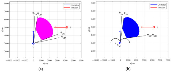
Figure 2.
Schematic diagram of violation areas of the well-clear zone for instantaneous and non-instantaneous track maneuvers of the ownship in the absolute coordinate system. (a) The diagram under instantaneous maneuvers. (b) Proposed diagram under non-instantaneous maneuvers.
3.2. Mathematical Model Under Non-Instantaneous Maneuver
As mentioned in Section 3.1, the model’s construction rests on computing conflict boundary angles and detecting conflicts in geometric space. For the non-instantaneous maneuver, the ownship executes left or right turns with a radius R, leading to continuous positional changes. This dynamic maneuvering invalidates the method of calculating the tangent to the well-clear zone by fixing the ownship at a specific position, as previously applicable in the instantaneous maneuver. Thus, adopting a novel methodology to ascertain the tangents between the relative trajectory and the well-clear zone is of paramount importance. Based on the ownship’s inability to immediately avoid conflicts, the computation of a recovery phase is essential. Thus, the proposed model will encompass both conflict and recovery phases.
3.2.1. Calculation and Detection of Boundary Angles in the Conflict Phase
Figure 1b illustrates the scenario of the ownship’s non-instantaneous maneuver. Over the time T, the distances traveled linearly by the ownship with varying relative velocities can be OE, JB, and KC. As an example, an algorithmic model is constructed for the ownship’s right-turn maneuver, using the UAV horizontal maneuvering dynamics model. The curve OL represents the relative motion trajectory formed by this right-turn maneuver, and its trajectory equation is outlined below. In Figure 2b, the conflict states under this maneuvering situation are also continuous, and the detection by applying the MidAngle theorem still holds.
In Equation (6), the trajectory equation characterizes the relative position, with . The angular velocity is denoted by , where is the gravitational acceleration. In particular, according to the DAIDALUS algorithm’s configuration, either the angular velocity or the roll angle can be specified. Therefore, the angular velocity is chosen to be set at [21]. The turning radius is given by . The time represents the duration of the aircraft’s right-turn maneuver under the angular velocity , with seconds. In addition, the relative velocity is calculated as follows.
In this paper, Cauchy’s inequality is utilized to find tangents between the relative trajectories of the two aircraft and the well-clear protected area. From Constraint (5), the condition effectively restricts the well-clear region between tangents IA and KD, as shown in Figure 1b, simplifying the original complex problem of identifying tangents to the relative trajectory within the entire well-clear region to the simpler task of determining the tangents of the trajectory with respect to a single protection circle. Based on the application of Cauchy’s inequality in solving for tangents between nonlinear curves and circular boundaries, this paper adopts Cauchy’s inequality to address the challenge of identifying the common tangent lines between the relative trajectories and the cylinder protection zone.
From Cauchy’s inequality, let two n-dimensional vectors , , satisfying . In coordinate form, this can be written as
Squaring both sides yields
Its inequality in two dimensions is
Assuming that the tangent point on the relative motion trajectory is expressed as , taking the derivation of Equation (6) yields
Thus, the equation of the tangent line at that point is
The tangent equation of the relative motion trajectory can be obtained. Let
Further, assume that there exists a point on the protected circle, and then
The expression of variable is determined from , and it lies within the interval: . Therefore, the intercept of the common tangent, which is denoted as , falls within the interval: . Further, the following equation is constructed by combining the endpoints of this range of with the intercept expression derived from the tangent line equation.
Here, denotes the upper tangent line sought, whereas denotes the lower tangent line sought. By setting the value for , the tangent equations for both the upper and lower tangents can be obtained, which can then be organized into the following expression:
However, we find that Cauchy’s inequality simplifies the problem of finding the upper and lower common tangents for the relative trajectory and the protected area, reducing the problem to a single nonlinear equation. In other words, the equations for determining the tangents IA and KD are exactly the same as those in Equation (17). By solving this equation, we can obtain times, and , at which the ownship maneuvers to points I and K. Subsequently, substituting these times into the following equation provides the conflict boundary track angles and of the ownship.
The relative flight states and are derived from Equations (6) and (7), and then the coordinates of are given by . According to the condition that the aircraft arrives at the boundary of the well-clear region at the prediction time T, from Equation (3), the boundary equation of the region can be formulated as follows:
TMOD is set to 35 s. T is the prediction time, which is usually 180 s. The coordinates of are then substituted to determine the time and for the aircraft to maneuver to points J and K. Through Equation (18), the angles and are further calculated. In Figure 1b, the point K is both the maneuvering point that reaches the protected boundary at the prediction time T and the tangent point, and thus .
The solution in the vertical dimension resembles the instantaneous maneuver model, including four distinct cases:
- (a)
- Both aircraft do not enter the protected area either vertically or horizontally.
- (b)
- Both aircraft do not enter vertically but do enter horizontally.
- (c)
- Both aircraft enter vertically but not horizontally.
- (d)
- Both aircraft enter the protected area both vertically and horizontally.
The crucial difference lies in the necessity to calculate, in all four cases, the maneuver angle at the protected area’s boundary achieved after executing both turning maneuvers and straight-line predictive maneuvers, particularly when entering or leaving the protected area vertically, thereby forming a novel maneuvering condition. Additionally, the time for vertically entering or exiting the protected zone, denoted as , is calculated as follows.
Cases (a) and (b) involve calculating with set to , whereas cases (c) and (d), which are already within the protected zone, require calculating with set to . Here, the represents the sign function. Let the coordinates of , denoted as , satisfy the new maneuvering condition, where is expressed as . Subsequently, the coordinates of are substituted into the equation , with the additional constraint , to ensure that lies within a physically meaningful region. Solving this equation yields the time t, representing the maneuvering turn moment when the aircraft crosses a critical boundary. This time t is then substituted into Equation (18) to obtain the new critical conflict track angle under vertical conflict, denoted as or .
After the aforementioned calculations, the angles , , , , , and required for generating the conflict prevention band under our model have been derived. Then, applying the MidAngle theorem to the intervals defined by these angles facilitates conflict detection. Here, the angles to represent the avoidance angles for the ownship, as depicted in Figure 1b. However, our model streamlines the iterative process of traversing all direction conflict states of the aircraft in the DAIDALUS algorithm by first identifying the critical track conflict boundary values and then detecting the relevant intervals. The utilization of the MidAngle theorem guarantees the congruence of conflict judgment results between the proposed model and the original DAIDALUS’s formal model.
3.2.2. Computation of Boundary Angles and Recovery Strategies in the Recovery Phase
The conflict boundary value in the recovery phase is derived from the initial three-dimensional well-clear violation interval, which is determined by solving a joint equation for both horizontal and vertical violation conditions, as illustrated by in Figure 3. However, in this paper is directly designated as the recommended right-turn recovery maneuver initiation point, marking the earliest deviation from the violation area. Furthermore, for multiple violation intervals, serves as the endpoint of the first right-turn interval, guiding the earliest possible safe direction, as depicted in Figure 3. By substituting into Equation (18), the recommended right-turn angle is obtained. This is then compared with the left-turn angle, and the direction with the smaller value is chosen. Based on these angles, the preventive band at this stage is directly generated, without further employment of the MidAngle theorem.
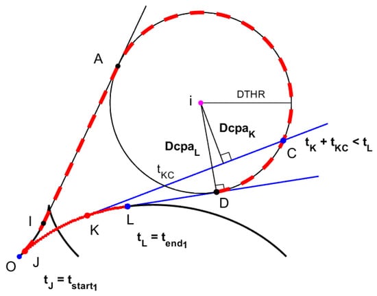
Figure 3.
Sketch map of the mathematical model of the conflict prevention algorithm in the recovery phase of the proposed model.
In addition, the bifurcation methodology employed in the DAIDALUS algorithm’s recovery model, as detailed in Section 2, explores a faster escape maneuver strategy, denoted as , with an equivalent angular representation , within the time interval denoted by . However, this approach inherently carries heightened risks in terms of flight duration and distance. As evident from Figure 3, the distance of the closest approach at point K, , is notably smaller than that at point L, . Moreover, comprehensively computing this strategy requires frequent utilization of the detection function. In contrast, the proposed model, during the recovery phase, offers a conservative and secure maneuvering strategy achieved through simplified computations.
4. Conflict Prevention Algorithm of the Proposed Model
Drawing upon the design architecture of the DAIDALUS algorithm, Algorithm 1 demonstrates how the proposed model generates the prevention bands of the ownship during the conflict and recovery phases.
| Algorithm 1: Conflict Prevention Algorithm of the proposed model |
| input: Flight states of the ownship and the intruder at a specified sampling time |
| output: A full 360-degree conflict prevention band of the ownship under the sampling moment |
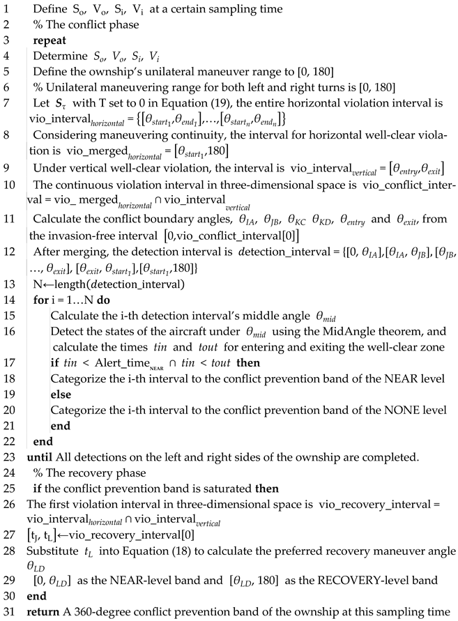 |
Algorithm 1 identifies a conflict prevention band for the ownship’s full track at each sampling instant. In the scenario where the ownship’s track concurrently falls within both right and left NEAR bands, the algorithm compares escape maneuver intervals for the respective NEAR zones, selecting the direction with the shorter interval as the preferred turning instruction. The aircraft then maneuvers accordingly, while the intruder maintains its original flight path. During each sampling moment, reassessing band saturation avoids unnecessary computations in the recovery phase.
Specifically, the times and are calculated to determine the entry and exit times of the aircraft into and out of the well-clear area, both horizontally and vertically, relative to the local coordinate system. These times are integrated to derive corresponding three-dimensional entry and exit times, as detailed in [21].
5. Simulation Analysis
5.1. Simulation Overview
To rigorously validate the proposed model’s accuracy and effectiveness, this study conducts comparative simulations and analyses between the two models across nine scenarios. This validation process leverages NASA’s publicly accessible test dataset, which has confirmed the validity of the DAIDALUS algorithm [26], focusing on a remotely piloted large-scale fixed-wing UAV. The scenarios are designed as follows: Scenarios 1 to 3 featured constant altitudes, while Scenarios 4 to 9 introduced vertical velocity variations for complexity. Notably, Scenarios 6 and 9 collectively recreate a real-world encounter scenario that resulted in a mid-air collision, as illustrated in [26]. For all scenarios, the aircraft status is updated every second, only focusing on NEAR alarms. In designing the ownship’s maneuvering strategy, a step size of 3°/s is adopted, balancing responsiveness with stability. To minimize the frequency of resolution maneuvers, the ownship is programmed to maintain a straight course at a constant speed for 10 s before regressing to its original direction.
5.2. Simulation Comparison
Initial flight states of both aircraft in all scenarios are specified in Appendix A. The ownship adjusts its trajectory in accordance with conflict prevention band directives to avoid collisions. To verify the consistency and accuracy of the model’s principles, we will contrast their prevention band data, reflecting the algorithm’s detection correctness. Furthermore, the iteration step size of the DAIDALUS algorithm exerts influence on detection accuracy, which in turn affects the precision of the prevention band and flight strategies, which is particularly noticeable in high-density scenarios. Thus, precision differences between the two models’ bands will be compared. In aircraft control, the time to closest point of approach (Tcpa) and distance to closest point of approach (Dcpa) serve as pivotal metrics in the assessment of collision avoidance safety levels for UAVs [28], with larger values indicating reduced risk and enhanced flight conditions, whereas smaller values suggest the opposite. Therefore, the comparative risk analysis will focus on the differences in the Tcpa and Dcpa between the models at each flight moment, calculated by subtracting the DAA model’s values from those of the proposed model.
Except for Scenarios 1 and 9, flight paths in the remaining scenarios are congruent between the two models. As illustrated in Figure 4 and Figure 5, our model exhibits a higher precision in the prevention band compared to the DAIDALUS model. Specifically, the precision improvements hover around approximately 0.2%, with slight variations, which facilitates a more precise delineation of conflict boundaries and the generation of accurate conflict intervals and instructions. This superiority arises from the proposed model’s capability to precisely calculate the geometric tangencies and intersectional lines that constitute the conflict boundaries, in contrast to the DAIDALUS algorithm’s reliance on a 3°/s iterative step size for detection. However, while reducing step size enhances accuracy, it also demands substantial computation, affecting the real-time performance of the system.
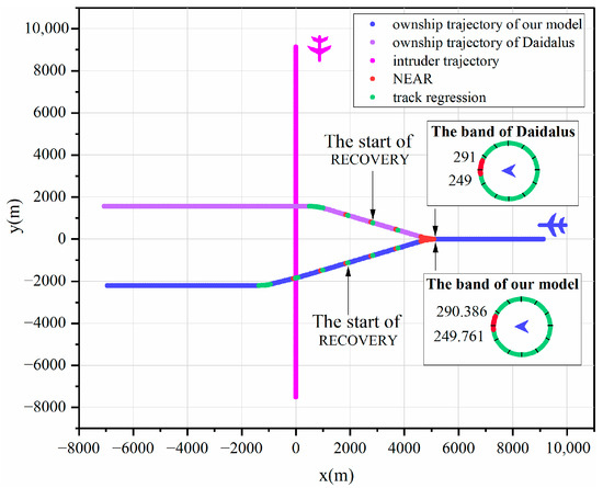
Figure 4.
Two-dimensional trajectory graphs for Scene 1.
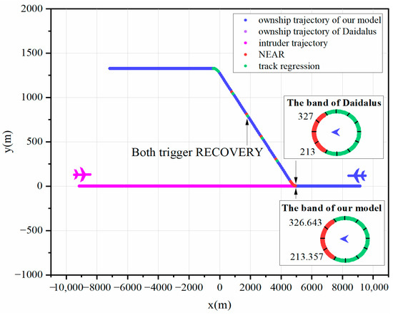
Figure 5.
Two-dimensional trajectory graphs for Scene 2.
An exhaustive analysis confirms the correctness of the proposed model. Figure 6, Figure 7, Figure 8 and Figure 9 demonstrate that both models ensure collision-free UAV operations, irrespective of whether the recovery phase is triggered. As demonstrated in Figure 10 and Figure 11, even with the added complexity posed by vertical altitude variations in the environment during horizontal maneuvering, the proposed model accurately computes conflict boundaries and maintains maneuvers consistent with the DAIDALUS algorithm through agile horizontal movements. Furthermore, in most scenarios, excluding Figure 6, Figure 11 and Figure 12, the proposed model effectively manages conflicts arising from track regression. The simultaneous initiation of maneuvers by both models across all scenarios underscores the success of the proposed model in intricate UAV detection and collision avoidance, thereby reinforcing its correctness.
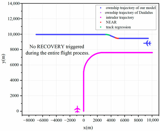
Figure 6.
Two-dimensional trajectory graphs for Scene 3.
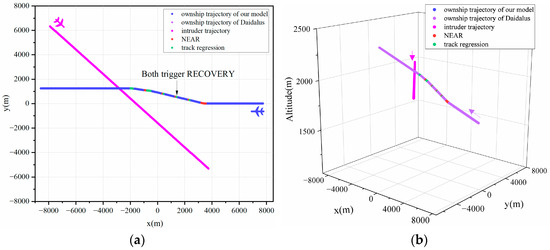
Figure 7.
Trajectory graphs for Scene 4. (a) Two-dimensional trajectory graphs. (b) Three-dimensional trajectory graphs.
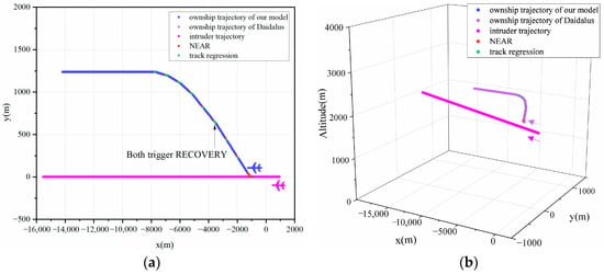
Figure 8.
Trajectory graphs for Scene 5. (a) Two-dimensional trajectory graphs. (b) Three-dimensional trajectory graphs.
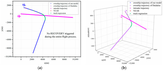
Figure 9.
Trajectory graphs for Scene 6. (a) Two-dimensional trajectory graphs. (b) Three-dimensional trajectory graphs.
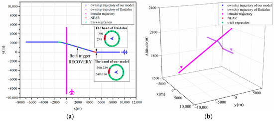
Figure 10.
Trajectory graphs for Scene 7. (a) Two-dimensional trajectory graphs. (b) Three-dimensional trajectory graphs.
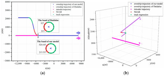
Figure 11.
Trajectory graphs for Scene 8. (a) Two-dimensional trajectory graphs. (b) Three-dimensional trajectory graphs.
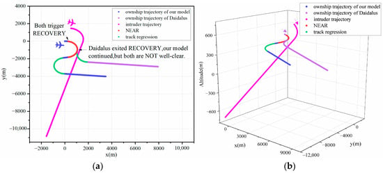
Figure 12.
Trajectory graphs for Scene 9. (a) Two-dimensional trajectory graphs. (b) Three-dimensional trajectory graphs.
Figure 13 affirms the proposed model’s comparability to the DAIDALUS in ensuring flight margins, and verifying operational safety and efficacy. While generally exhibiting similar safety and collision resolution abilities, in Scenario 1, the larger Tcpa of the model stems from variations in the initial maneuver, resulting from differences in detection accuracy, and allowing for an extended resolution time. Meanwhile, in Scenario 9, when encountering the largest negative ΔTcpa, the Dcpa of both models exceed the Near Mid-Air Collision (NMAC) radius of 152 m, but the proposed model boasts a larger Dcpa value, which generates an S-shaped path and then emphasizes a longer warning time and safety margins, as shown in Figure 12. This is because the maneuvering, derived from straightforward equations, can yield greater distance buffers than DAIDALUS’s faster resolution path, validating its superior safety performance. Its comparable but enhanced safety in specific scenarios, in line with DAIDALUS’s efficacy, underscores the proposed model’s safety credentials and operational viability.
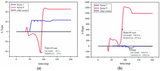
Figure 13.
Variation curves of the time difference (ΔTcpa) and the distance difference (ΔDcpa) at the closest point of approach (CPA) during flights across all scenarios. (a) Variation curves of the time difference (ΔTcpa). (b) Variation curves of the distance difference (ΔDcpa).
6. Conclusions
In this study, the DAIDALUS algorithm developed at NASA Langley Research Center is meticulously examined under the DAA architecture. Given that the effectiveness of the DAIDALUS algorithm has been prevalently verified, this study further delves into its modeling analysis. Based on its formal model, this paper analyzes and proposes a mathematical model for the horizontal track conflict prevention algorithm. Firstly, utilizing UAV maneuvering dynamics and Cauchy’s inequality, we effectively tackle the tangent problem between relative trajectory and the well-clear protected zones, making the delineation of the conflicting track boundaries in three-dimensional space straightforward. The MidAngle theorem enhances detection accuracy among boundaries, streamlining computations beyond the iterative methods of the original model. Secondly, a new recovery maneuver rule is presented to provide a safer strategy for the DAIDALUS algorithm at the closest point. Finally, the two-phase algorithm implementation steps of the proposed model are specified. The simulation results show that the proposed model not only provides high-precision preventive bands and aligns closely with the DAIDALUS algorithm’s maneuvers and trajectories across most scenarios, but also ensures collision-free UAV navigation in all scenarios, exhibiting a stability comparable to its formal model. Moreover, in specific scenarios, our model employs a conservative recovery maneuvering strategy, offering larger buffers that enhance safety. This study confirms the correctness and efficacy of our model, and further validates the correctness of the formal model, while the recovery optimization strategy establishes valuable theoretical foundations and supports for subsequently improving the DAIDALUS algorithm’s performance. Further research will focus on refining the horizontal speed model and considering the measurement error’s effect on the model.
Author Contributions
Conceptualization, S.W. and Y.L.; methodology, S.W. and Y.L.; software, S.W.; validation, S.W. and Y.L.; formal analysis, S.W.; investigation, S.W.; resources, Y.L.; data curation, S.W. and Y.L.; writing—original draft preparation, S.W.; writing—review and editing, S.W., Y.Z. and Y.L.; visualization, S.W. and Y.Z.; supervision, Y.L.; project administration, Y.L. All authors have read and agreed to the published version of the manuscript.
Funding
This research received no external funding.
Data Availability Statement
The original contributions presented in this study are included in the article; further inquiries can be directed to the corresponding author.
Conflicts of Interest
The authors declare no conflicts of interest.
Appendix A
Initial states for all scenes of the ownship and the intruder aircraft for all scenarios are as follows.

Table A1.
Initial flight states of the two aircraft for all scenarios.
Table A1.
Initial flight states of the two aircraft for all scenarios.
| Scenario | Range, m | Horizontal Direction, Degrees | Horizontal Speed, m/s | Altitude, m | Vertical Speed, m/s |
|---|---|---|---|---|---|
| 1 | 12,908.0 | O 1 = 270 T = 180 | O = 82.3 | O = 1981.2 | O = 0 |
| T = 82.3 | T = 1981.2 | T = 0 | |||
| 2 | 18,279.0 | O = 270 | O = 82.3 | O = 1981.2 | O = 0 |
| T = 90 | T = 82.3 | T = 1981.2 | T = 0 | ||
| 3 | 13,353.0 | O = 270 | O = 82.3 | O = 1981.2 | O = 0 |
| T = 0 to 90 | T = 82.3 | T = 1981.2 | T = 0 | ||
| 4 | 16,872.0 | O = 270 | O = 82.3 | O = 1698.4 | O = 2.54 |
| T = 135 | T = 82.3 | T = 1981.2 | T = 0 | ||
| 5 | 1870.5 | O = 270 | O = −66.9 | O = 1981.2 | O = 0 |
| T = 270 | T = 82.3 | T = 1780.5 | T = 2.54 | ||
| 6 | 1557.9 | O = 100 | O = 66.4 | O = 607.5 | O = −6.76 |
| T = 95 | T = 47.8 | T = 452.0 | T = −1.81 | ||
| 7 | 12,908.0 | O = 270 | O = 82.3 | O = 1981.2 | O = 0 |
| T = 0 | T = 82.3 | T = 1698.4 | T = 2.54 | ||
| 8 | 0.0 | O = 270 | O = 82.3 | O = 2590.8 | O = −2.54 |
| T = 270 | T = 82.3 | T = 1981.2 | T = 0 | ||
| 9 | 1557.9 | O = 95 | O = 47.8 | O = 452.0 | O = −1.81 |
| T = 100 | T = 66.4 | T = 607.5 | T = −6.76 |
1 O: the ownship; T: the intruder aircraft.
References
- Tan, Y.; Wang, J.; Liu, J.; Kato, N. Blockchain-Assisted Distributed and Lightweight Authentication Service for Industrial Unmanned Aerial Vehicles. IEEE Int. Things J. 2022, 9, 16928–16940. [Google Scholar] [CrossRef]
- Marques, P.; Pádua, L.; Sousa, J.J.; Fernandes-Silva, A. Advancements in Remote Sensing Imagery Applications for Precision Management in Olive Growing: A Systematic Review. Remote Sens. 2024, 16, 1324. [Google Scholar] [CrossRef]
- Zhang, Z.; Zhu, L. A Review on Unmanned Aerial Vehicle Remote Sensing: Platforms, Sensors, Data Processing Methods, and Applications. Drones 2023, 7, 398. [Google Scholar] [CrossRef]
- Liao, Y.; Jia, Z.; Dong, C.; Zhang, L.; Wu, Q.; Hu, H.; Han, Z. Interference Analysis for Coexistence of UAVs and Civil Aircrafts Based on Automatic Dependent Surveillance-Broadcast. IEEE Trans. Veh. Technol. 2024, 1–5. [Google Scholar] [CrossRef]
- Liao, Y.; Jia, Z.; Dong, C.; Zhang, L.; Wu, Q.; Hu, H.; Han, Z. Sharing airspace with Uncrewed Aerial Vehicles (UAVs): Views of the General Aviation (GA) community. J. Air. Transp. Manag. 2022, 102, 102218. [Google Scholar] [CrossRef]
- Guan, X.; Lyu, R.; Shi, H.; Chen, J. A survey of safety separation management and collision avoidance approaches of civil UAS operating in integration national airspace system. Chin. J. Aeronaut. 2020, 33, 2851–2863. [Google Scholar] [CrossRef]
- Hu, J.; Wang, T.; Zhang, H.; Pan, Q.; Zhang, J.; Xu, Z. A review of rule-based collision avoidance technology for autonomous UAV. Sci. China Technol. Sci. 2023, 66, 2481–2499. [Google Scholar] [CrossRef]
- Lieb, J.; Volkert, A. Unmanned Aircraft Systems Traffic Management: A Comparison on the FAA UTM and the European CORUS ConOps Based on U-Space. In Proceedings of the 2020 IEEE/AIAA 39th Digital Avionics Systems Conference (DASC), San Antonio, TX, USA, 11 October 2020; pp. 1–6. [Google Scholar]
- Lappas, V.; Zoumponos, G.; Kostopoulos, V.; Lee, H.I.; Shin, H.-S.; Tsourdos, A.; Tantardini, M.; Shomko, D.; Munoz, J.; Amoratis, E.; et al. EuroDRONE, a European Unmanned Traffic Management Testbed for U-Space. Drones 2022, 6, 53. [Google Scholar] [CrossRef]
- Tang, J.; Lao, S.; Wan, Y. Systematic Review of Collision-Avoidance Approaches for Unmanned Aerial Vehicles. IEEE Syst. J. 2022, 16, 4356–4367. [Google Scholar] [CrossRef]
- Yu, S.; Park, J. Collision Avoidance Algorithm for a Fixed-Wing UAV Utilizing Geometric Estimation Considering Multiple Dynamic Obstacles. Int. J. Aeronaut. Space Sci. 2024, 25, 1–18. [Google Scholar] [CrossRef]
- Krozel, J.; Peters, M. Strategic Conflict Detection and Resolution for Free Flight. In Proceedings of the 36th IEEE Conference on Decision and Control, San Diego, CA, USA, 12 December 1997; pp. 1822–1828. [Google Scholar]
- Gnanasekera, M.; Katupitiya, J. A Time Optimal Reactive Collision Avoidance Method for UAVs Based on a Modified Collision Cone Approach. In Proceedings of the 2020 IEEE/RSJ International Conference on Intelligent Robots and Systems (IROS), Las Vegas, NV, USA, 24 October 2020; pp. 5685–5692. [Google Scholar]
- Zhuang, J.; Zhang, Y.; Xu, P.; Zhao, Y.; Luo, J.; Song, S. Multiple Moving Obstacles Avoidance for USV using Velocity Obstacle Method. In Proceedings of the 2021 IEEE International Conference on Unmanned Systems (ICUS), Beijing, China, 15 October 2021; pp. 140–145. [Google Scholar]
- Ma, H.; Cai, Z.; Xu, G.; Yang, G.; Chen, G. Dynamic Smooth and Stable Obstacle Avoidance for Unmanned Aerial Vehicle Based on Collision Prediction. Optim. Control. Appl. Methods 2023, 45, 737–757. [Google Scholar] [CrossRef]
- Van den Berg, J.; Lin, M.; Manocha, D. Reciprocal Velocity Obstacles for Real-Time Multi-Agent Navigation. In Proceedings of the 2008 IEEE International Conference on Robotics and Automation, Pasadena, CA, USA, 19 May 2008. [Google Scholar]
- Tan, C.Y.; Huang, S.; Tan, K.K.; Huat Teo, R.S. Three Dimensional Collision Avoidance for Multi Unmanned Aerial Vehicles Using Velocity Obstacle. J. Intell. Robot. Syst. 2020, 97, 227–248. [Google Scholar] [CrossRef]
- Zhang, H.; Zhang, J.; Zhong, G.; Liu, H.; Liu, W. Multivariate Combined Collision Detection for Multi-Unmanned Aircraft Systems. IEEE Access 2022, 10, 103827–103839. [Google Scholar] [CrossRef]
- Zhang, S.; Xu, T.; Cheng, H.; Liang, F. Collision Avoidance of Fixed-Wing UAVs in Dynamic Environments Based on Spline-RRT and Velocity Obstacle. In Proceedings of the 2020 International Conference on Unmanned Aircraft Systems (ICUAS), Athens, Greece, 1 September 2020; pp. 48–58. [Google Scholar]
- He, Y.; Shi, X.; Lu, J.; Zhao, C.; Zhao, G. Grouping Formation and Obstacle Avoidance Control of UAV Swarm Based on Synchronous DMPC. Int. J. Aerospace Eng. 2024, 2024, 4934194. [Google Scholar] [CrossRef]
- Muñoz, C.; Narkawicz, A.; Hagen, G.; Upchurch, J.; Dutle, A.; Consiglio, M.; Chamberlain, J. DAIDALUS: Detect and Avoid Alerting Logic for Unmanned Systems. In Proceedings of the 2015 IEEE/AIAA 34th Digital Avionics Systems Conference (DASC), Prague, Czech Republic, 13 September 2015; pp. 5A1-1–5A1-12. [Google Scholar]
- A Mathematical Basis for the Safety Analysis of Conflict Prevention Algorithms. Available online: https://ntrs.nasa.gov/citations/20090025481 (accessed on 18 August 2024).
- LeCun, Y.; Bengio, Y.; Hinton, G. Deep learning. Nature 2015, 521, 436–444. [Google Scholar] [CrossRef] [PubMed]
- Park, K.; Kim, J. Aircraft Collision Avoidance Modeling and Optimization Using Deep Reinforcement Learning. Inst. Control Robot. Syst. 2021, 27, 652–659. [Google Scholar] [CrossRef]
- Young Ryu, J.; Lee, H.; Lee, H.-T. Detect and Avoid AI System Model Using a Deep Neural Network. In Proceedings of the 2022 IEEE/AIAA 41st Digital Avionics Systems Conference (DASC), Portsmouth, VA, USA, 18 September 2022; pp. 1–8. [Google Scholar]
- Evaluation, Analysis and Results of the DANTi Flight Test Data, the DAIDALUS Detect and Avoid Algorithm, and the DANTi Concept for Detect and Avoid in the Cockpit. Available online: https://ntrs.nasa.gov/citations/20205004594 (accessed on 18 August 2024).
- RTCA-DO-365: Minimum Operational Performance Standards (MOPS) for Detect and Avoid (DAA) System. Available online: https://www.document-center.com/standards/show/RTCA-DO-365 (accessed on 18 August 2024).
- Errico, A.; Di Vito, V. A Method for Evaluating Aircraft Dependencies Using the Closest Point of Approach Methodology to Support ATM Operations. In Proceedings of the 33th Congress of the International Council of the Aeronautical Sciences (ICAS), Stockholm, Sweden, 4 September 2022. [Google Scholar]
Disclaimer/Publisher’s Note: The statements, opinions and data contained in all publications are solely those of the individual author(s) and contributor(s) and not of MDPI and/or the editor(s). MDPI and/or the editor(s) disclaim responsibility for any injury to people or property resulting from any ideas, methods, instructions or products referred to in the content. |
© 2024 by the authors. Licensee MDPI, Basel, Switzerland. This article is an open access article distributed under the terms and conditions of the Creative Commons Attribution (CC BY) license (https://creativecommons.org/licenses/by/4.0/).