Article

Active Disturbance Rejection Flight Control and Simulation of Unmanned Quad Tilt Rotor eVTOL Based on Adaptive Neural Network

Nanjing Department of Helicopter, Aviation College, University of Aeronautics and Astronautics, Nanjing 210016, China
*
Author to whom correspondence should be addressed.
Drones 2024, 8(10), 560; https://doi.org/10.3390/drones8100560
Submission received: 21 September 2024 / Revised: 4 October 2024 / Accepted: 6 October 2024 / Published: 8 October 2024
(This article belongs to the Section Drone Design and Development)

Abstract

:
The unmanned quad tilt-rotor eVTOL (QTRV) is a variable-configuration aircraft that combines the features of vertical takeoff and landing (VTOL), hovering, and high-speed cruising, making its control system design particularly challenging. The flight dynamics of the QTRV differ significantly between the VTOL and cruise modes, and are further influenced by rotor tilt and external wind disturbances. Developing a unified, highly coupled nonlinear full-flight dynamics model facilitates flight control system design and simulation verification. To ensure stable tilt of the QTRV, a tilt corridor was established, along with the design of its tilt route and manipulation strategy. An adaptive neural network active disturbance rejection controller (ANN-ADRC) is proposed to ensure stable flight across all modes, reducing the control parameters and simplifying tuning while effectively estimating and compensating for unknown disturbances in real time. A hardware-in-the-loop (HIL) simulation system was designed for full-mode flight control simulation, and the results demonstrated the effectiveness of the proposed control method.

1. Introduction

The tilt-rotor eVTOL combines the advantages of helicopters and fixed-wing aircraft, featuring high cruising speed, long range, and large payload capacity, along with vertical takeoff and landing capabilities. It plays a significant role in applications such as firefighting, reconnaissance, agriculture, and traffic monitoring, making it a popular aircraft configuration currently being researched [1,2]. In order to further improve the load capacity, cruising speed, and range, an unmanned quad tilt-rotor eVTOL (QTRV) with a front and rear parallel quad-rotor layout was designed based on the traditional configuration [3,4]. The change in the configuration of the aircraft results in it exhibiting multi-body dynamics, variability, and complexity. It can operate in three distinct flight modes: helicopter, fixed-wing, and a transitional mode between the two. The tilting motion of the rotors causes significant differences in the mechanical structure and aerodynamic characteristics of the aircraft across these three modes. In flight in helicopter mode and fixed-wing mode, the aerodynamic effects of the wings, ailerons, rudder, and other components are different, which not only leads to serious coupling issues but also leads to control redundancy [5,6]. Aircraft are also affected by external disturbances such as wind gusts. This makes QTRV flight dynamics modeling difficult and brings challenges to the design of the flight control system [7,8].
Regarding tilt-rotor aircraft, a variety of flight control system design methods have been proposed. Naya et al. [9] developed a six-degree-of-freedom mathematical model and a transition corridor for a tri-tilt-rotor UAV. They validated a novel PD controller using simulation methods. Andi et al. [10] used an LQR (Linear Quadratic Regulator) controller to achieve attitude stabilization control for a small quad tilt-rotor aircraft. Anna and Erdal [11] developed a mathematical model for a tilt-rotor UAV and conducted trim analysis. They implemented trajectory tracking for the aircraft using both PID controllers and a linear model predictive controller.
Compared to linear control, nonlinear control can be effective over a wider range of flight envelopes. Gerardo et al. [12] designed a transition strategy from hovering to horizontal flight for a tilt-rotor quadcopter and developed a nonlinear control law based on the Lyapunov function to ensure stable flight. Marcelino et al. [13] designed a cascade nonlinear controller for a tilt-rotor with feedback linearization under suspension load. Gabriele et al. [14] used a nonlinear dynamic inversion method to design a flight controller for a ducted tilt-rotor aircraft. They effectively addressed the control redundancy issue through optimized control allocation and developed a transition strategy for moving from hovering to forward flight. Xinhua et al. [15] designed a finite-time convergence observer using the Lyapunov function, and the flight controller designed based on the observer was able to smoothly achieve the flight mode switching of a quad tilt-rotor (QTR). Leonard et al. [16] proposed a model predictive control (MPC) method which can ensure the flight of a QTR in different flight modes through control allocation. Stephen et al. [17] designed a transition flight strategy from hovering to forward flight for a tilt-rotor UAV based on the backstepping method, and implemented the control algorithm on an embedded controller, achieving experimental validation. Although the aforementioned nonlinear controller achieved flight control for the nonlinear model of the tilt-rotor aircraft, it lacked consideration of the impact of internal and external disturbances on flight control. Qian et al. [18] analyzed the interference mechanisms of wind fields on tilt-rotor aircraft and proposed a robust control method based on an extended state observer. This approach enhanced the flight control of the tilt-rotor aircraft, providing good attitude tracking and disturbance rejection capabilities. Yanchao et al. [19] proposed a neural network sliding-mode controller, which ensured the convergence of the sliding surface through neural network nonlinear approximation errors. This approach improved the disturbance rejection and robustness of the tilt-rotor quad-rotor attitude controller. Siddharth et al. [20] proposed an improved sliding-mode controller for a QTR, and the robustness of the controller was proven by a simulation and an experiment. Guang et al. [21] added a disturbance observer to the sliding mode controller to reduce buffeting, and designed an attitude controller, a position controller, and a control allocation strategy. The disturbance rejection and robustness of the flight control system were verified by simulation experiments with external interference and parameter variation. Danyu et al. [22] proposed a specified-time sliding-mode control scheme for the trajectory tracking of a tilt-rotor eVTOL aircraft, designing a specified-time prescribed performance function (ATPPF) to serve as the expected error value, ensuring that the error converges to zero within a designated time. The simulation results demonstrated the effectiveness of the specified-time control strategy under conditions of external disturbances, dynamic uncertainties, and control input constraints.
The extended state observer of the active disturbance rejection controller (ADRC) can estimate the total disturbances of the flight control system and compensate in real time, effectively overcoming the uncertainties of internal and external disturbances [23,24]. However, the adaptive ability of an ESO is not strong enough, and its disturbance estimation ability will decrease obviously once the flight environment of the QTRV changes significantly. Adaptive neural networks possess strong robustness and adaptability [25,26]. In this paper, an adaptive neural network combined with an ESO is used to design a novel ADRC to improve the adaptive ability of the control system.
The sections of this article are organized as follows: Section 2 establishes the QTRV flight dynamics model, designs control strategies for different flight modes, obtains the tilt corridor and designs the tilt route through a vehicle-mounted running test. Section 3 combines the ESO with an adaptive radial basis neural network, designs an ANN-ADRC, builds a trajectory-tracking control system, and designs collective pitch–pitch angle switching rules. Section 4 carries out QTRV hardware-in-the-loop attitude control simulation and trajectory-tracking control simulation. Section 5 presents a summary of this research.

2. Model Description and Analysis

2.1. Flight Dynamics Modeling

The structural layout of the QTRV, which consists of wings, a vertical tail, a tilting mechanism, a transmission mechanism, a power device, navigation, a controller, and four sets of rotors and nacelles, is shown in Figure 1. The rotors, wings, vertical tail, and fuselage are the main pneumatic components, and the geometric parameters of the four sets of rotors are completely consistent. The main parameters are shown in Table 1.
When establishing a rotor aerodynamic model, consider the following dynamic characteristics:
(1)
The aerodynamic model of blade is established by using the blade element theory.
(2)
The rotor-induced velocity is calculated using the Pitt–Peters dynamic inflow model [27].
(3)
The flapping motion of the rotor only considers the first-order flapping of the blade.
The aerodynamic interference from the rotor of the QTRV on the wing can create additional downward loads, which should be taken into account during modeling [28]. We establish dynamic models for the rotor, wing, vertical tail, and fuselage of the QTRV. By integrating the aerodynamic forces and gravitational forces of each component, the flight dynamics equations of the QTRV can be obtained using the momentum theorem and the angular momentum theorem [29,30]:
X ˙ Y ˙ Z ˙ T = R E B V x V y V z T V ˙ x V ˙ y V ˙ z T = F m Ω V x V y V z T w ˙ x w ˙ y w ˙ z T = I 1 M I 1 Ω I w x w y w z T ϕ ˙ θ ˙ ψ ˙ T = E α w x w y w z T
R E B = C θ C ψ S θ S ψ C ψ - C f S ψ S θ C f C ψ + S f S ψ C θ S ψ S θ S f S ψ + C f C ψ S θ C f S ψ - S f C ψ - S θ S f C θ C f C θ
Ω = 0 - w z w y w z 0 - w x - w y w x 0 E α = 1 S f T θ C f T θ 0 C f - S f 0 S f / C θ C f / C θ
In this equation, ϕ θ ψ is the vector of the roll, pitch, and yaw Euler angles, w x w y w z is the angular rate vector, V x V y V z is the body-axis linear velocity vector, V x V y V z is the position vector in the Earth frame, F = F x F y F z is the resultant external force vector, M = M x M y M z is the resultant external moment vector, I = d i a g I x I y I z is the inertia tensor, m is the UAV mass, R E B is the coordinate transformation matrix from the body axis system to the Earth axis system, Ω is the angular rate transformation matrix, and E α is the transformation matrix from the body angular rate to the Euler angular rate. S θ , S ϕ , S ψ , C θ , C ϕ , C ψ , C θ , C ϕ , C ψ is short for a trigonometric function.

2.2. Manipulation Strategy Design

Each pair of QTRV rotors has three control inputs, collective pitch and longitudinal and lateral cyclic pitch, and the control strategy is different in the three flight modes. The manipulation strategies are different in the three flight modes. Table 2 shows the manipulation strategies for helicopter mode and fixed-wing mode. The transition flight mode refers to the process of converting from helicopter mode to fixed-wing mode. The manipulation strategies achieve the conversion of flight mode through a change in the weight coefficients. The conversion relationship is as follows:
φ Y = Y a w × W H , δ Y = Y a w × W F φ R = R o l l × W H , δ R = R o l l × W F φ P = P i t c h × W H , δ P = P i t c h × W F φ C = C o l × W H , δ C = C o l × W F
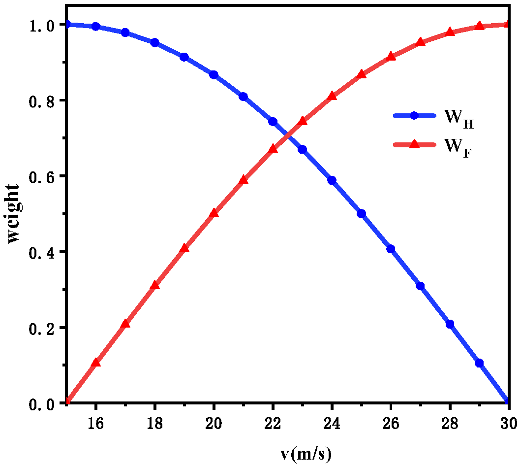
In this equation, φ Y , φ R , φ P and φ C are the manipulation quantity of each channel in helicopter mode. δ Y , δ R , δ P and δ C are the manipulation quantity of each channel in fixed-wing mode. Yaw, Roll, Pitch, and Col are the manipulation quantities of the heading channel, lateral channel, longitudinal channel, and vertical channel, respectively. WH and WF represent the weights for different channel manipulations in helicopter mode and fixed-wing mode, respectively. The variations in these manipulation weights are shown in Figure 2.

2.3. Tilt Corridor Measurement

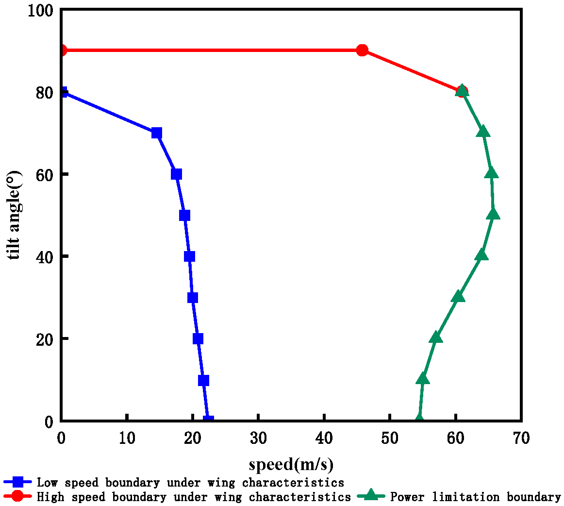
The matching relationship between rotor tilt angle and forward flight speed affects the safety of QTRV tilt transition flight. When the rotor tilts, if the front speed is too low, the wing lift will be too small. When the front speed is too high, the zero-lift resistance will be too large, which cannot compensate for the lift loss caused by the rotor tilting forward, so the flight height is reduced and the flight safety is endangered. Due to the limitation of the available power of the rotor motor, the forward flight speed cannot be increased indefinitely. Therefore, each rotor tilt angle will have corresponding minimum and maximum forward flight speeds, forming a relationship curve between rotor tilt angle and forward flight speed, that is, the envelope line formed by the minimum and maximum speed boundaries under different tilt angles when the QTRV transitions from helicopter mode to fixed-wing mode.
The low speed boundary is determined by the lift characteristics of the wing, the high speed boundary is determined by the available power limitation of the motor, and the tilt corridor is obtained by a vehicle-mounted running test.

2.3.1. Wing Lift Characteristics Limitation

During QTRV flight, it is essential to keep the wing’s angle of attack within a safe range. The stall angle and zero-lift angle of the wing correspond to the upper and lower limits of the wing’s lift characteristics, respectively. The safe range for the wing’s angle of attack can be determined using Equation (5):
α f m i n ( α i , s t a l l ) - m a x ( α i , 0 ) α f m a x ( α i , W 0 ) - m i n ( α i , 0 )
In this equation, α f represents the angle of attack of the fuselage, α i , s t a l l is the stall angle of the corresponding wing, min( α i , s t a l l ) denotes the minimum of the four values; α i , W 0 indicates the zero-lift angle of the corresponding wing, max( α i , W 0 ) denotes the maximum of the four values, and α i , 0 is the initial installation angle of the corresponding wing.
To ensure flight safety, the QTRV must satisfy the following force equation when flying at low speed:
L + T s i n ( β t + α f ) = G
T c o s ( β t + α f ) - D = 0
In this equation, L represents the lift generated by the wings, T denotes the thrust from the rotors, G is the total weight of the UAV, D refers to the total drag on the UAV, and α i , 0 indicates the rotor tilt angle.

2.3.2. Rotor Power Limitation

The available power limitation boundary of a single rotor can be expressed as:
m a x ( P r , i ) P e
In the equation, P r , i represents the power required by the corresponding rotor with a specific number, and P e indicates the rated power output of a single motor. The power required by a single rotor can be expressed as follows:
P r = 1 η p ( P i + P p r + P p + P c )
In the equation, η p represents the transmission loss coefficient, P i denotes the induced power, P p r indicates the profile drag power, P p refers to the waste resistance power, and P c represents the climb power.
During forward flight of the QTRV, the component of rotor thrust must not be less than the total drag of the aircraft, and the power required by the rotor must not exceed the available power from the motor. The following equation must be satisfied during high-speed flight of the QTRV:
L + T s i n ( β t + α f ) = G
T c o s ( β t + α f ) - D = 0
P x y < P k y
In this equation, D represents the drag experienced by the UAV, Pky denotes the total available power from all motors, and Pxy indicates the power required by all rotors, Pxy = 4Pr.

2.3.3. Vehicle-Mounted Running Test

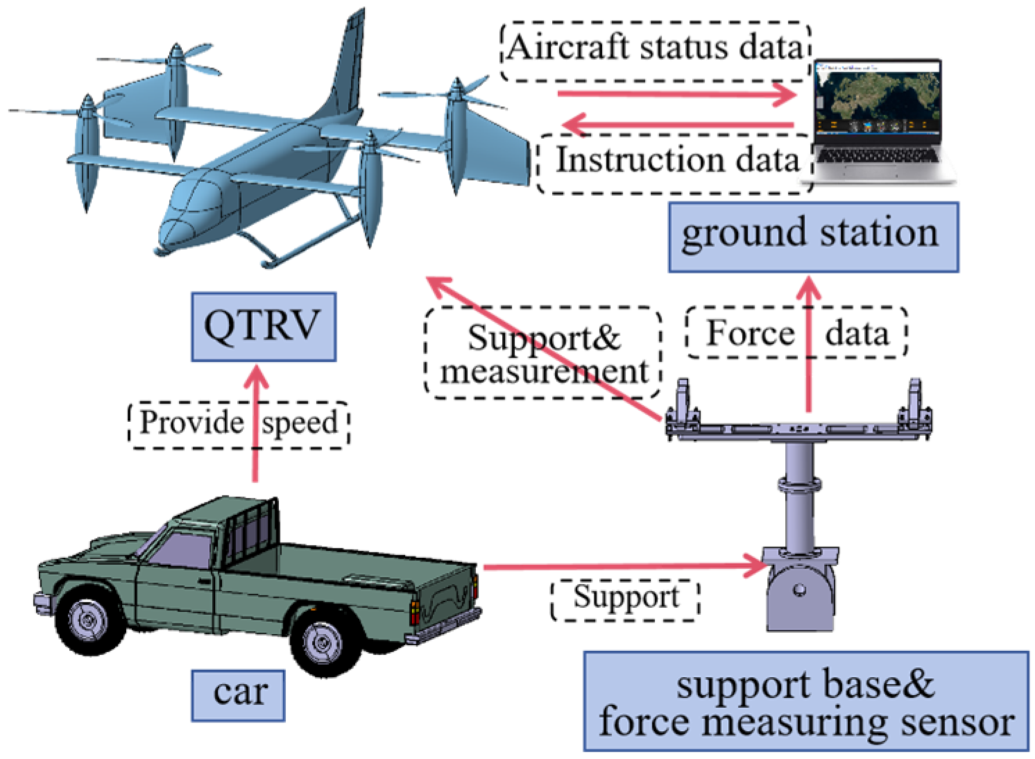
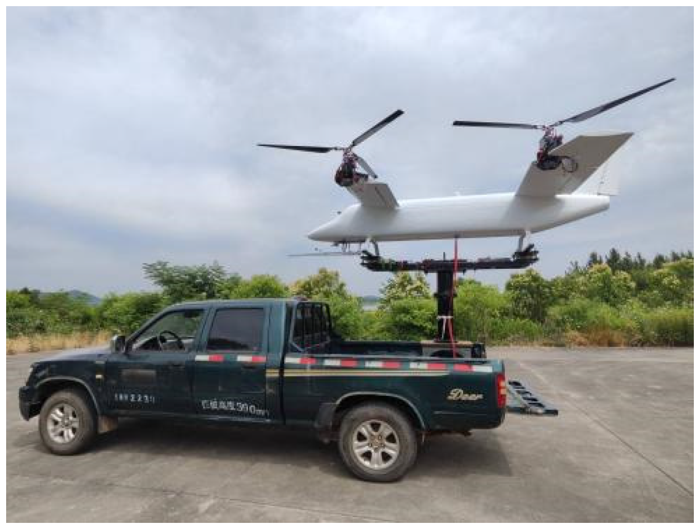
Compared to wind tunnel tests, the vehicle-mounted running test effectively reduces costs and improves efficiency, while also ensuring higher safety and reliability. To measure the transition corridor of the tilt quad-rotor UAV, a vehicle-based testing system is designed, as shown in Figure 3. This system consists of a car, a support base, a force scale, and the UAV. The support base can elevate the UAV above the height of the car, minimizing the ground effect and interference from the wake of the car’s roof. The car carries the aircraft and drives straight at a certain speed, simulating an aerial flight environment. The force-measuring sensor measures the force and torque exerted on the aircraft in real time. The ground station records the forces and moments corresponding to different flight speeds and different rotor tilt angles during the test. The tilt corridor of the QTRV is obtained by analyzing the test data. The vehicle-mounted QTRV is shown in Figure 4.
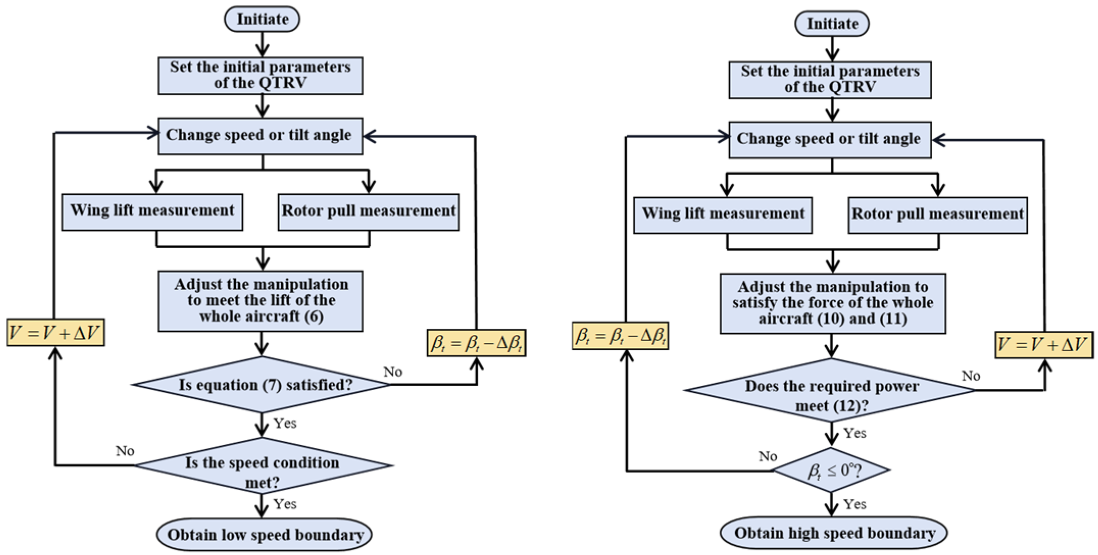
The required test data can be measured according to the measurement steps in Figure 5. The tilt corridor obtained by the analysis is shown in Figure 6.

2.3.4. Tilt Route

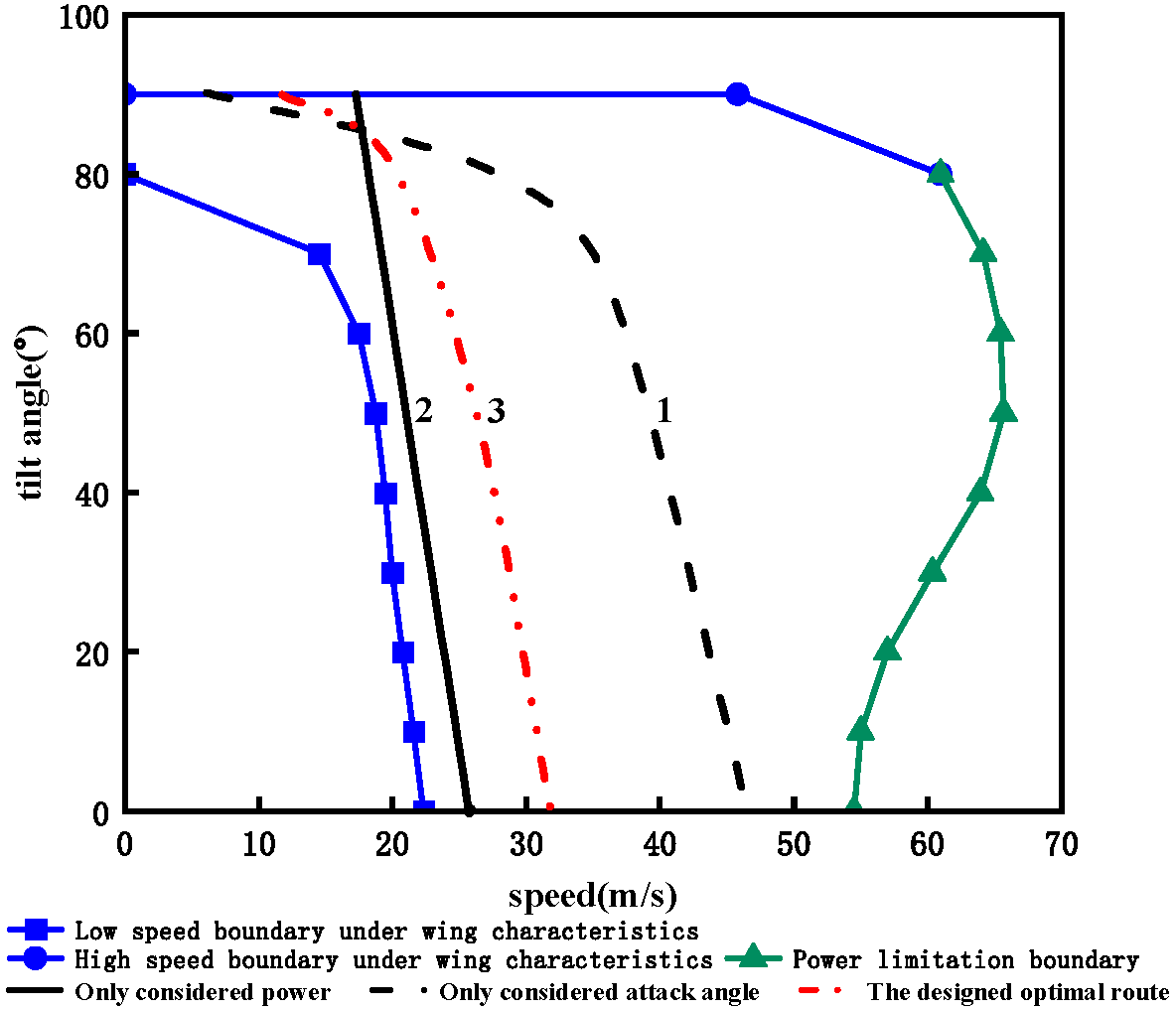
The tilt corridor is a collection of all feasible transition paths. Based on angle of attack and power evaluation criteria, an optimal set of tilt points can be selected, resulting in a rational tilt route. During the transition flight, the more stable the QTRV attitude is, the safer it is. The less power it requires, and the more surplus power available for maneuvering or attitude adjustment, the safer it is.
The design safety cost function is:
C S = w 1 θ θ min Δ θ max + w 2 P P min Δ P max
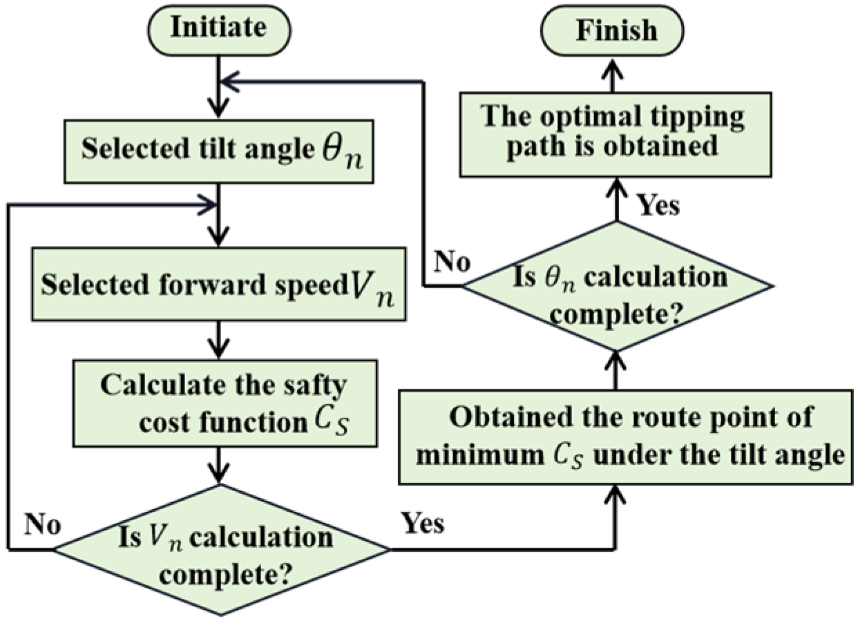
Only the attack angle evaluation criterion is considered, that is, when w1 = 1 and w2 = 0, all feasible tilt points are traversed and calculated, and the tilt route obtained is shown as route 1 in Figure 7. Only considering the power evaluation criteria, that is, when w1 = 0 and w2 = 1, all feasible tilt points are traversed and calculated, and the tilt route obtained is shown as path 2 in Figure 7. When the attack angle and power evaluation criteria are considered comprehensively, that is, when w1 = 0.5 and w2 = 0.5, route 3 in Figure 7 can be obtained according to the calculation process shown in Figure 8, that is, the considered reasonable tilt route.

3. Trajectory-Tracking Control Design

3.1. ANN-ADRC

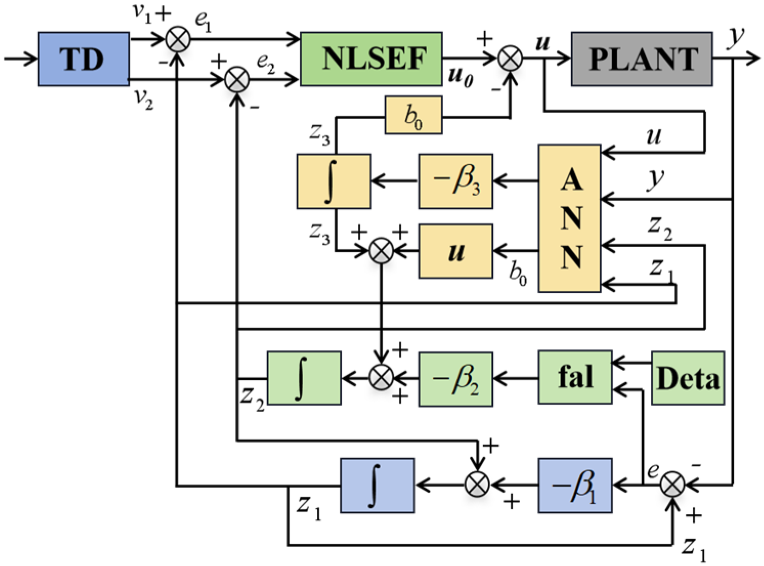
The traditional ADRC control structure, as shown in Figure 9, includes an extended state observer (ESO) that estimates internal and external disturbances to form a total disturbance, which is the core component. The tracking differentiator (TD) enables rapid tracking of the input signal and provides its differential signal. The Nonlinear State Error Feedback (NLSEF) law is used to compensate for the total disturbance and generate the control output [31,32]. There are many parameters in the ADRC. The difficulty of tuning the control parameters can be reduced and the effectiveness of disturbance estimation can be improved by designing an ANN-ADRC. The structure of the ANN-ADRC is shown in Figure 10.

3.1.1. TD

We express the nonlinear tracking differentiator for a second-order system in discrete form:
v 1 ( k + 1 ) = v 1 ( k ) + h v 2 ( k ) v 2 ( k + 1 ) = v 2 ( k ) + h × f s t ( v 1 ( k ) - v ( k ) )
d = r h d 0 = h d y = v 1 + h v 2 a 0 = d 2 + 8 r y a = v 2 + ( a 0 - d ) 2 s i g n ( y ) , y > d 0 v 2 + y / h , y £ d 0 f s t ( v 1 , v 2 , r , h ) = - r s i g n ( a ) , a > d - r a / d , a £ d
In this equation, k represents the number of signal samples, v is the input signal, v1 is the tracking signal of v, v2 is the differential signal of v, h denotes the signal sampling period, and r represents the speed parameter. Both h and r can influence the speed of the signal.

3.1.2. ANN-ESO

Adaptive neural network algorithms can be used to approximate unknown nonlinear functions:
λ ( ξ ) = W * T Φ ( ξ ) + ε ( ξ )
Φ j ( ξ ) = e x p - ξ - η j 2 2 σ j 2
In this equation, ξ = [ ξ i ] T (i = 1, 2, … n) represents the input signals to the neural network, while Φ = [ Φ i ] T (j = 1, 2, … m) denotes the output signals from the hidden layer, with Φ j being the output signal of the j-th neuron in the hidden layer. η j = [ η 1 j η 2 j η n j ] T represents the coordinate vector of the center of the Gaussian basis function for the j-th neuron, σ j = [ σ 1 σ 2 σ n ] T , σ j is the Gaussian basis function of the j-th neuron, W * T is the ideal weight of the neural network, and ε is the error value that the neural network aims to approximate, ε ( ξ ) ε N .
Using ANN to approximate an unknown function, let the network input be denoted as ξi. The network output can then be expressed as:
λ ^ ( ξ ) = W ^ T Φ ( ξ )
In this equation, W ^ represents the estimated value of the ideal weights W * . The unknown second-order nonlinear system equation is:
x ˙ 1 = x 2 x ˙ 2 = x 3 + b u x ˙ 3 = w ( t ) y = x 1
In this equation, u is the system input signal, y is the output signal, x1 and x2 represent the state variables, x3 denotes the extended state variable, and b represents the system gain. The established ESO is:
ε = z 1 - y z ˙ 1 = z 2 - β 01 ε z ˙ 2 = z 3 - β 02 f a l ( ε , α 1 , δ ) + b u z ˙ 3 = - β 03 f a l ( ε , α 2 , δ )
f a l ( ε , α i , δ ) = ε δ α - 1 , ε δ ε α s i g n ( ε ) , ε > δ
In this equation, zi (i = 1, 2, 3) represents the output variable signals of the ESO, αi (i = 1, 2) and β0i (i = 1, 2, 3) denote the step size parameters, and fal represents the nonlinear function.
The state equations of a typical second-order nonlinear system can be expressed as:
x ˙ = A x + b ( f ( x ) + g ( x ) u + d ( t ) ) y = C T x A = 0 1 0 0 ,   b = 0 1 ,   C = 1 0
In this equation, x = [x1, x2] represents the state vector of the system, and y denotes the output vector of the system. f(x) and g(x) are unknown nonlinear functions, and d(t) represents external disturbances, satisfying d ( t ) D .
To analyze the above second-order system, a state observer can be designed as follows:
x ^ ˙ = A x ^ + b ( f ^ ( x ^ ) + g ^ ( x ^ ) u - v ( t ) ) + K ( y - C T x ^ ) y ^ = C T x ^
In this equation, x ^ is the estimated value of x, K = [K1, K2]T represents the gain of the state observer, and v(t) denotes the robust term. f(x) and g(x) are unknown nonlinear functions. The estimates f ^ ( x ^ ) and g ^ ( x ^ ) can be obtained through approximation using ANN.
The state equation for the ESO of ADRC can be expressed as:
x ˙ 1 = x 2 x ˙ 2 = f ^ ( x ^ ) + g ^ ( x ^ ) u x ˙ 3 = f ^ ( x ^ ) y = x 1
The f ^ ( x ^ ) estimated by the ANN can be used as the approximation of the total disturbance z3, and g ^ ( x ^ ) can be used as the approximation of the control gain b. Then, the control compensation of the system can be obtained, and the system can be converted to a standard linear control system.

3.1.3. NLSEF

NLSEF is used to perform a nonlinear combination of the error obtained by comparing the tracking signal and differential signal from the TD with the estimated state variable signals from the ANN-ESO, namely:
e 1 = v 1 - z 1 e 2 = v 2 - z 2 u 0 = β 1 f a l ( e 1 , λ 1 , τ ) + β 2 f a l ( e 2 , λ 2 , τ ) u = u 0 - z 3 / b
f a l ( e i , λ , τ ) = e i τ 1 - λ , e i τ e α s i g n ( e i ) , e i > τ
In this equation, u0 represents the error feedback variable, β1 and β2 are adjustable gain parameters, and the fal function has a filtering capability to suppress oscillations in the output signal.

3.2. Trajectory-Tracking Control System

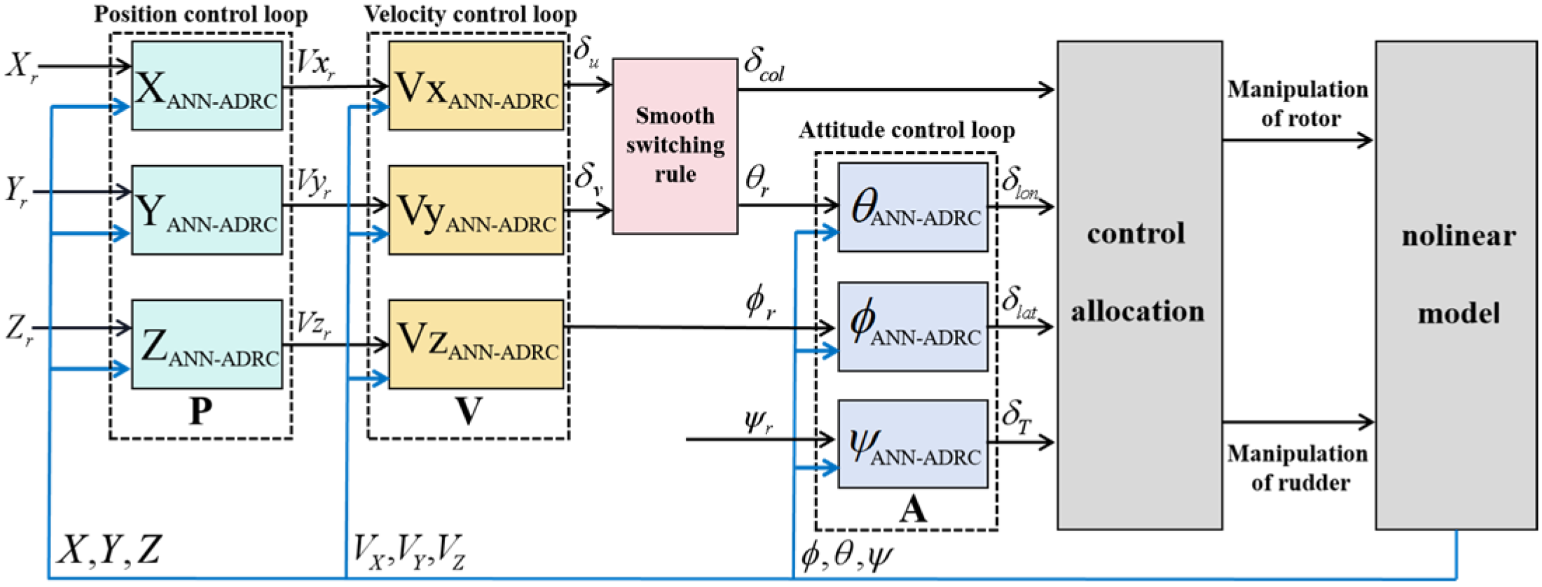
The design of the QTRV trajectory-tracking control system is shown in Figure 11, comprising a nonlinear flight dynamics model, a manipulation strategy, and an ANN-ADRC flight control law. The control loop consists of attitude control, velocity control, and position control loops. By processing the input and output information of each control loop, the control quantities for the lateral, longitudinal, heading, and vertical channels can be computed. These channel control quantities are then allocated to the QTRV actuators by the control strategy, resulting in changes in the state response of the flight dynamics model.

3.2.1. Attitude Control Loop

The following can be seen from Formula (1):
α = f ˙ θ ˙ ψ ˙ T , w α = w ˙ x w ˙ y w ˙ z T α ˙ = F 1 ( α ) w α w ˙ α = F 2 ( α , w α , V α , Ω , w r ) + B ( α , w α , V α , Ω , w r ) u α
In this equation, wr represents the external disturbances affecting the system, and u α = [ δ l o n , δ l a t , δ T ] denotes the control vector. From Equation (27), the second-order state equations can be derived as follows:
α ¨ = d F 1 d t w α + w ˙ α F 1 = F 3 w α + F 1 ( F 2 + B u α )
In this equation, F3 = dF1/dt, F1, and F2 and B are abbreviations for the corresponding functions in Equation (27). Defining the total disturbance as f α = F 3 w α + F 1 ( F 2 + B u α ) B 0 α u α , Equation (28) can be further expressed as:
α ¨ = f ¯ α + B 0 α u α
In this equation, B 0 α represents the attitude control gain matrix. The roll and pitch angle commands are provided by the speed loop, while the yaw angle command is given by a reference signal. The three signals serve as inputs to the attitude loop, and the control quantity u α = [ δ l o n , δ l a t , δ T ] is the output of the attitude loop. At this point, the control quantities for the roll, pitch, and yaw channels form a single input–single output relationship with their corresponding desired target attitude angles, as illustrated by module A in Figure 11.

3.2.2. Velocity Control Loop

The following can be seen from Formula (1):
V α = V ˙ x V ˙ y V ˙ z T V ˙ α = F 4 ( α , w α , V α , w r )
If we define the disturbance as f ¯ V = F 4 ( α , w α , V α , w r ) - B 0 V u V , then:
V ˙ α = f ¯ V + B 0 V u V
In this equation, B 0 V is the gain matrix for the velocity control. The velocity controller operates before the attitude controller, with the velocity command provided by the position loop serving as the signal input for the velocity loop. The control quantity uV = [ δ u , δ v , ϕ r ] is the output of the velocity loop. The velocity control loop is represented by module V in Figure 11.

3.2.3. Position Control Loop

The following can be seen from Formula (1):
P = X ˙ Y ˙ Z ˙ T P ˙ = F 5 ( α , w r ) u P
If we define the disturbance as f ¯ P = ( F 5 ( α , w r ) - B 0 P ) u P , then:
P ˙ = f ¯ p + B 0 P u P
In this equation, B 0 P is the gain matrix for position control. The position controller operates before the velocity controller, with the desired trajectory command serving as the signal input for the position loop. The control quantity uP = [ V x r , V y r , V z r ] is the output of the position loop. The position control loop is represented by module P in Figure 11.

3.3. Collective Pitch–Pitch Angle Switching Rules

In the early stages of helicopter mode and transition mode, the vertical speed control of the QTRV primarily relies on total distance, while forward speed control is mainly achieved through pitch attitude adjustment. In the later stages of the transition mode and during fixed-wing mode, vertical speed control is predominantly managed through pitch attitude adjustment, whereas forward speed control focuses on total distance. As the flight modes change, the types of control variables also shift, necessitating the design of a total distance–pitch angle switching rule during the transition phase to ensure stable and smooth vertical and forward speed control. As shown in Figure 12, the switching rule is designed as follows:
δ c o l = δ v × C c o l + δ u × C θ θ r = δ v × C θ + δ u × C c o l
In this equation, δ c o l is the collective pitch input, θ r is the pitch channel controller input, δ v is the vertical speed controller output, δ u is the forward speed controller output, C c o l is the collective pitch input weight, and C θ is the pitch controller input weight.
During QTRV transition flight, the collective pitch–pitch angle switching rules are different, the altitude change will be different. In order to reduce the altitude change in the aircraft during transition flight, the tilt angle was taken as the variable, and the altitude-tracking accuracy was taken as the evaluation condition for the quality of the tilt transition. The Sigmoid function, trigonometric function, and linear function were used to switch the collective pitch and pitch angle to compare the altitude-tracking effect. The change rules of the three functions are shown in Figure 12. The simulation results and errors of altitude-tracking control in the process of vertical takeoff, tilt acceleration, uniform-speed forward flight, reverse tilt deceleration, and vertical landing achieved by the QTRV are shown in Figure 13 and Figure 14. The simulation and error results show that the switching rule of collective pitch–pitch angle according to the Sigmoid law can minimize the altitude change.

4. Hardware-in-the-Loop (HIL) Simulation

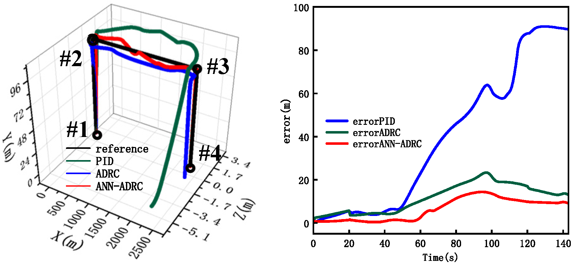
The mechanical structure and dynamic characteristics of the QTRV are complicated, so it is more dangerous to carry out flight test directly. The HIL is used to verify the flight control system design of the aircraft before the flight test, which can reduce the development cost, shorten the development period, and improve the system reliability and the success rate of flight test. The QTRV HIL system is shown in Figure 15 and it consists of a ground station, an airborne flight controller, numerical simulation software, visual simulation software, an SD card, and communication equipment. The airborne flight controller uses the embedded processor STM32H750XBH6 as its core. The ground station sends flight target instructions via a wireless data transmission radio to the airborne flight controller, where these commands are integrated with the actual flight states to calculate the manipulation for the rotors and control surfaces, and then sent to the aircraft dynamics numerical simulation model by the serial communication equipment to calculate the real-time state response of the aircraft. The state variables are transmitted to the airborne flight controller and visual simulation software by the serial communication equipment. The SD card in the airborne flight controller stores flight target instructions and flight state data for subsequent data analysis.

4.1. Stability and Robustness Simulation

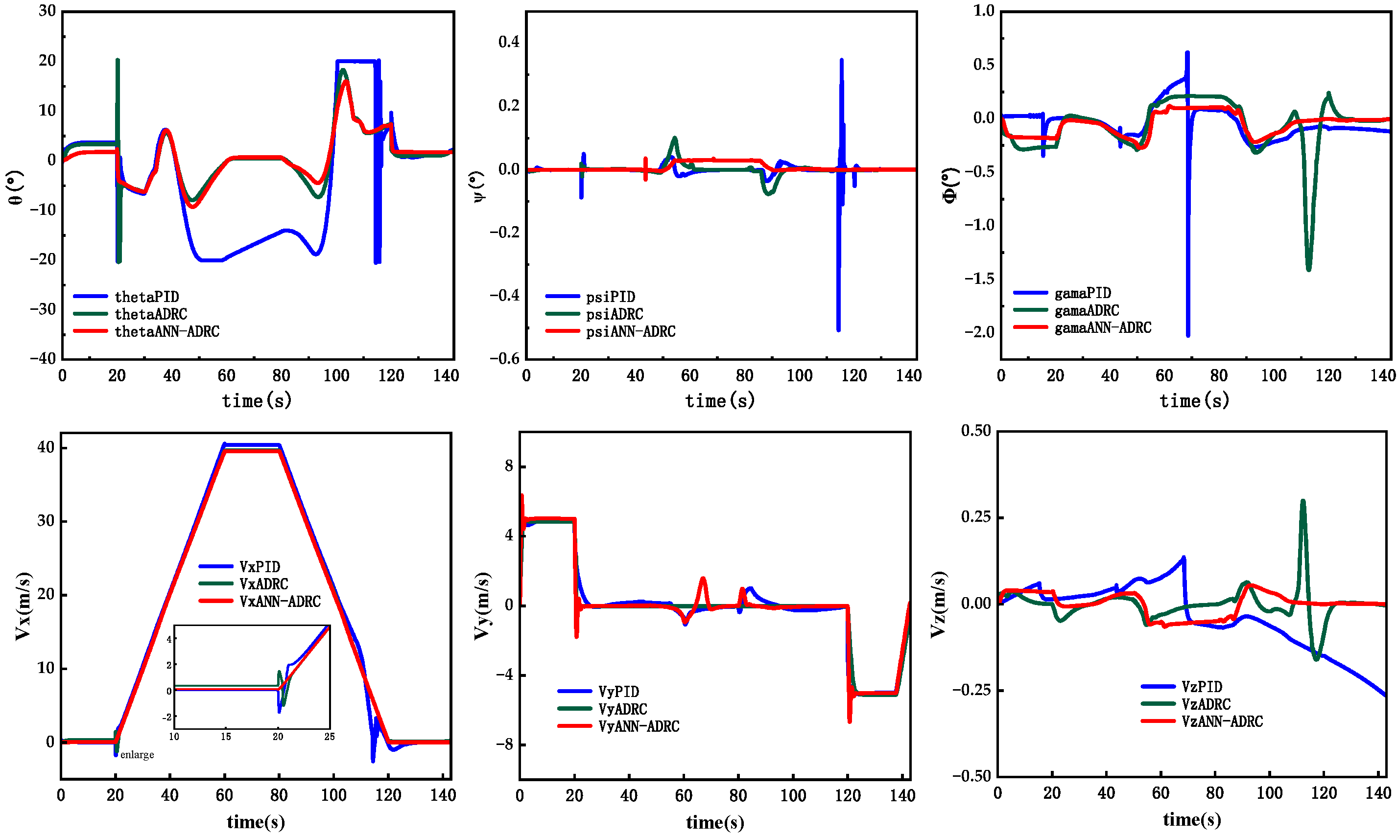
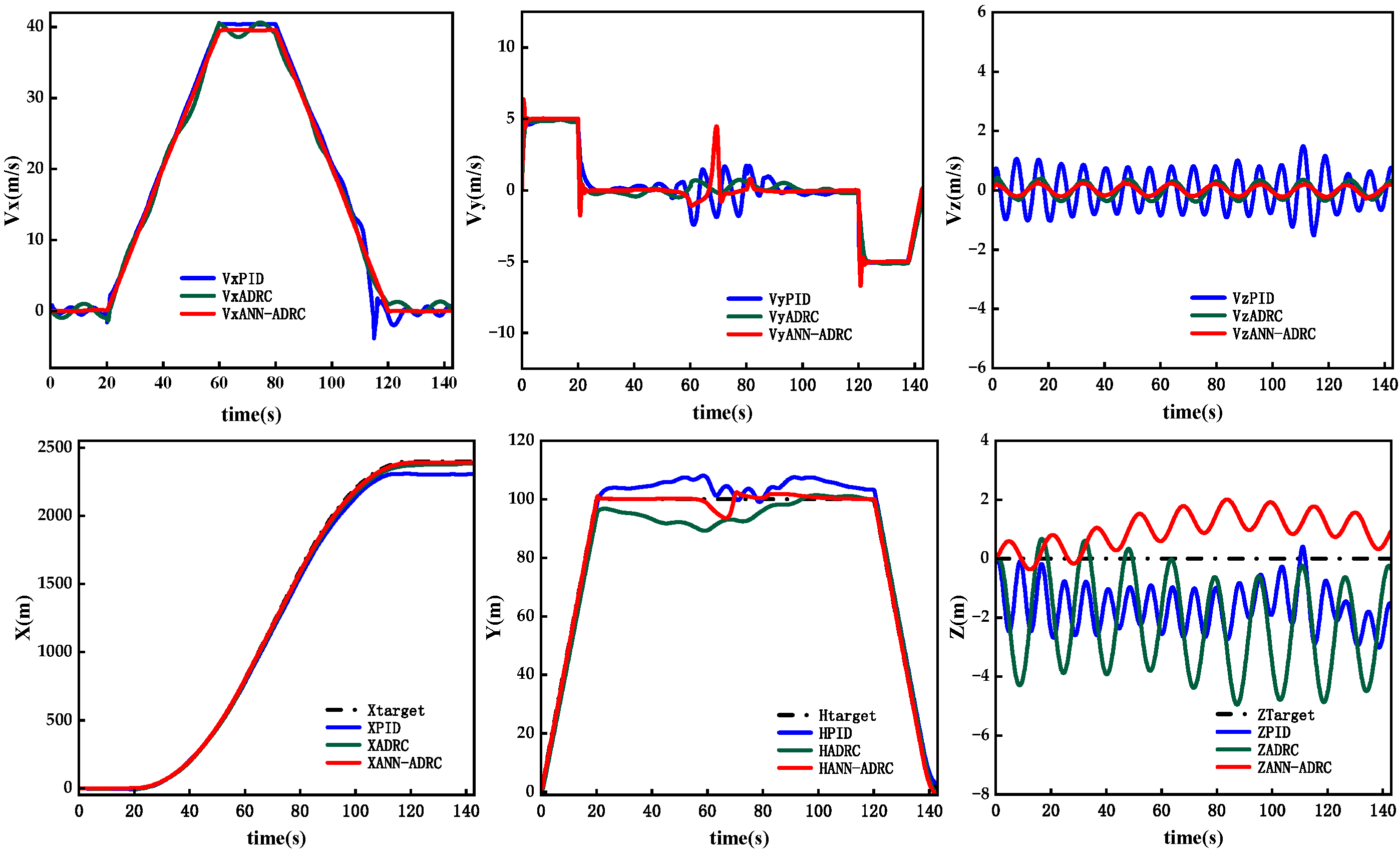
The QTRV full flight mode trajectory consists of four track points, and each track point is defined by three-axis coordinates and axial velocity in the Earth’s axis coordinate system, as shown in Figure 16. In order to achieve autonomous trajectory flight, the QTRV flight mode is designed as follows: vertical takeoff, accelerated forward flight, cruising flight, decelerated forward flight, and lastly, vertical descent. The HIL process includes the following steps: At 0–20 s, the QTRV takes off vertically in helicopter mode at a 5 m/s vertical speed to enter altitude hold. After a short hover, it tilts and accelerates forward in transition mode in 20–60 s. At 60–80 s, it cruises at a 40 m/s forward speed in fixed-wing mode. At 80–120 s, it reverses its tilt and decelerates in transition mode. At 120–143 s, it gradually reduces its vertical speed in helicopter mode and descends vertically to a slow touchdown. The distance error between the target reference trajectory and the actual flight trajectory during flight is shown in Figure 16. And the attitude, velocity, and position-tracking results are shown in Figure 17. The simulation results show that when the QTRV flies in different modes, the attitude-, velocity- and trajectory-tracking stability of the ANN-ADRC is stronger than that of the traditional ADRC and PID controller, and the control accuracy is higher. When the QTRV accelerates forward flight and decelerates forward flight in transition mode, its tilt angle changes, that is, the internal parameters of the aircraft change at this time. The altitude control accuracy of the ANN-ADRC is better than that of the traditional ADRC and PID controller, and the attitude retention performance is better, indicating that the robustness of the ANN-ADRC is stronger.

4.2. Disturbance Rejection Simulation

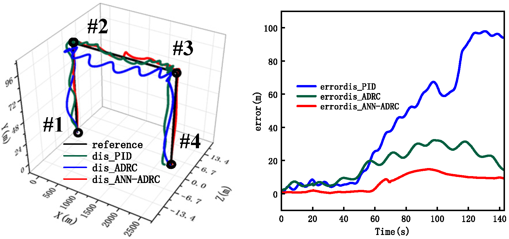
In the QTRV disturbance rejection simulation, the trajectory points are set and defined in the same manner as in Section 4.1. External wind disturbance with a peak of 2 m/s and a frequency of 0.8 rad/s is added to the three-axis inflow velocity of the aircraft. The three-dimensional trajectory-tracking results and errors are shown in Figure 18. The HIL simulation process is identical to that in Section 4.1, including vertical takeoff to an altitude of 100 m and maintaining that height, accelerating into a tilt-forward flight at a speed of 40 m/s, cruising at a forward speed of 40 m/s, decelerating to tilt-forward until the speed reaches 0, and then descending vertically to land gently. The tracking results for the aircraft’s attitude, speed, and position under wind disturbances are shown in Figure 19. From the simulation results, it is evident that under external wind disturbances, the ANN-ADRC provides higher precision in attitude, speed, and trajectory tracking when the QTRV flies in different modes, with smaller oscillation amplitudes. Particularly when the tilt angle changes, the traditional ADRC and PID controller exhibit significant jitter in attitude and speed, leading to a noticeable decrease in trajectory-tracking accuracy. In contrast, the ANN-ADRC maintains good control performance, indicating stronger disturbance rejection capability.

5. Conclusions

This paper establishes a flight dynamics model for the QTRV and designs a reasonable manipulation strategy for the aircraft. It calculates the tilt transition corridor and develops a suitable tilt route. ANN-ADRC based on an ANN-ESO is proposed, utilizing the ANN to approximate the unknown disturbance terms in the extended state observer, and combining the estimated state values from the observer to generate the controller output. A trajectory-tracking flight control system for the QTRV is developed based on the ANN-ADRC, overcoming the impacts of internal and external disturbances and achieving full-mode flight control for the aircraft. The HIL simulation results indicate that this controller maintains stable state responses in different flight modes, with the stability, disturbance rejection capability, and robustness of the ANN-ADRC outperforming those of the traditional ADRC and PID controller.

Author Contributions

B.D. is responsible for the design of the main test tasks and manuscript writing, J.X. is responsible for reviewing and proofreading, X.Y. is responsible for writing the flight control programs, and S.Y. is responsible for writing the communication programs. All authors have read and agreed to the published version of the manuscript.

Funding

This research was funded by the National Key Laboratory of Helicopter Dynamics Fund Program of China (9140C400504130C4148) and supported by the Priority Academic Program Development of Jiangsu Higher Education Institutions of China.

Data Availability Statement

No new data were created.

Conflicts of Interest

The authors declare no conflict of interest.

References

  1. Liu, Z.; Didier, T.; Yang, L.; He, Y.; Han, J. Observer-based linear parameter varying control design with unmeasurable varying parameters under sensor faults for quad-tilt rotor unmanned aerial vehicle. Aerosp. Sci. Technol. 2019, 92, 696–713. [Google Scholar] [CrossRef]
  2. Metehan, Y.; Ali, T.K.; Murat, S.; Osman, G. An Adaptive Flight Controller Design for a Tilt-Prop Fixed Wing UAV for All Flight Modes. In AIAA Scitech 2020 Forum; Aerospace Research Central: Orlando, FL, USA, 2020; pp. 1–20. [Google Scholar]
  3. Yunus, G.; Sheikh MB, M.; Raunak, R.; Basman, E.; Erdal, K. Unsteady aerodynamic modeling and control of pusher and tilt-rotor quadplane configurations. Aerosp. Sci. Technol. 2019, 94, 105421. [Google Scholar]
  4. Ye, L.; Zhang, Y.; Yang, S.; Zhu, X.; Dong, J. Numerical simulation of aerodynamic interaction for a tilt rotor aircraft in helicopter mode. Chin. J. Aeronaut. 2016, 28, 843–854. [Google Scholar] [CrossRef]
  5. Chen, C.; Zhang, J.; Shen, L. Control and flight test of a tilt-rotor unmanned aerial vehicle. Int. J. Adv. Robot. Syst. 2017, 14, 1729881416678141. [Google Scholar] [CrossRef]
  6. Liu, Z.; He, Y.; Yang, L.; Han, J. Control techniques of tilt rotor unmanned aerial vehicle systems: A review. Chin. J. Aeronaut. 2017, 30, 135–148. [Google Scholar] [CrossRef]
  7. Daniel NCardoso Sergio, E.; Guilherme, V.R. A new robust adaptive mixing control for trajectory tracking with improved forward flight of a tilt-rotor UAV. ISA Trans. 2021, 110, 86–104. [Google Scholar]
  8. Lv, Z.Y.; Wu, Y.; Zhao, Q.; Sun, X.M. Design and Control of a Novel Coaxial Tilt-Rotor UAV. IEEE Trans. Ind. Electron. 2022, 69, 3810–3821. [Google Scholar] [CrossRef]
  9. Navya, T.H.; George, V.I.; Gurudas, N.C. Modelling and Transition flight control of Vertical Take-Off and Landing unmanned Tri-Tilting Rotor Aerial Vehicle. In Proceedings of the ICECA, Coimbatore, India, 12–14 June 2019. [Google Scholar]
  10. Dharmawan, A.; Ashari, A.; Putra, A.E. Translation movement stability control of quad tiltrotor using LQR and LQG. I. J. Intell. Syst. Appl. 2018, 10, 10–21. [Google Scholar] [CrossRef]
  11. Prach, A.; Kayacan, E. An MPC-based position controller for a tilt-rotor tricopter VTOL UAV. Optim. Control. Appl. Methods 2018, 39, 343–356. [Google Scholar] [CrossRef]
  12. Flores-Colunga, G.R.; Lozano-Leal, R. A Nonlinear Control Law for Hover to Level Flight for the Quad Tilt-rotor UAV. IFAC Proc. Vol. 2016, 47, 11055–11059. [Google Scholar] [CrossRef]
  13. Almeida, M.M.; Raffo, G.V. Nonlinear Control of a TiltRotor UAV for Load Transportation. IFAC-Pap. 2015, 48, 232–237. [Google Scholar]
  14. Di, F.G.; Mattei, M. Modeling and Incremental Nonlinear Dynamic Inversion Control of a Novel Unmanned Tiltrotor. J. Aircr. 2016, 53, 73–85. [Google Scholar]
  15. Wang, X.; Cai, L. Mathematical Modeling and Control of a Tilt-Rotor Aircraft. Aerosp. Sci. Technol. 2015, 47, 473–492. [Google Scholar] [CrossRef]
  16. Bauersfeld, L.; Spannagl, L.; Ducard, G.J.; Onder, C.H. MPC Flight Control for a Tilt-Rotor VTOL Aircraft. IEEE Trans. Aerosp. Electron. Syst. 2021, 57, 2395–2409. [Google Scholar] [CrossRef]
  17. Nogar, S.M.; Kroninger, C.M. Development of a Hybrid Micro Air Vehicle Capable of Controlled Transition. IEEE Robot. Autom. Lett. 2018, 3, 2269–2276. [Google Scholar] [CrossRef]
  18. Zhang, Q.; Zhang, J.; Wang, X.; Xu, Y.; Yu, Z. Wind Field Disturbance Analysis and Flight Control System Design for a Novel Tilt-Rotor UAV. IEEE Access 2020, 8, 211401–211410. [Google Scholar] [CrossRef]
  19. Yin, Y.; Niu, H. Adaptive Neural Network Sliding Mode Control for Quad Tilt Rotor Aircraft. Complexity 2017, 2017, 7104708. [Google Scholar] [CrossRef]
  20. Sridhar, S.; Kumar, R.; Gupta, G.; Kumar, M.; Cohen, K. Nonlinear control of a novel class of tilt-rotor quadcopters using sliding mode method: Theory and hardware implementation. J. Aerosp. Eng. 2022, 35, 211401–211410. [Google Scholar] [CrossRef]
  21. He, G.; Yu, L.; Huang, H.; Wang, X. A Nonlinear Robust Sliding Mode Controller with Auxiliary Dynamic System for the Hovering Flight of a Tilt Tri-Rotor UAV. Appl. Sci. 2020, 10, 6551. [Google Scholar] [CrossRef]
  22. Li, D.; Zhang, L.; Mo, C.; Cui, N. Application of Improved Appointed Time Control in Helicopter Mode of a Tilt-rotor eVTOL Aircraft. Aerosp. Sci. Technol. 2024, 153, 109447. [Google Scholar] [CrossRef]
  23. Han, J. From PID to Active Disturbance Rejection Control. IEEE Trans. Ind. Electron. 2009, 56, 900–906. [Google Scholar] [CrossRef]
  24. Deng, B.; Xu, J. Trajectory Tracking Based on Active Disturbance Rejection Control for Compound Unmanned Aircraft. Aerospace 2022, 9, 313. [Google Scholar] [CrossRef]
  25. Su, B.; Zhang, F.; Huang, P. Stability Analysis and RBF Neural Network Control of Second-Order Nonlinear Satellite System. IEEE Trans. Aerosp. Electron. Syst. 2022, 59, 4575–4589. [Google Scholar] [CrossRef]
  26. Xia, R.; Chen, M.; Wu, Q.; Wang, Y. Neural network based integral sliding mode optimal flight control of near space hypersonic vehicle. Aerosp. Sci. Technol. 2020, 379, 41–52. [Google Scholar] [CrossRef]
  27. Gaonkar, G.; Peters, D. Review of Dynamic Inflow Modelling for Rotorcraft Flight Dynamics. In Proceedings of the 27th Structures, Structural Dynamics and Materials Conference, San Antonio, TX, USA, 19–21 May 1986. [Google Scholar]
  28. Ronan, B. Numerical analysis of rotor/propeller aerodynamic interactions on a high-speed compound helicopter. J. Am. Helicopter Soc. 2022, 67, 1–15. [Google Scholar]
  29. Simmons, B.M.; Gresham, J.L.; Woolsey, C.A. Aero-Propulsive Modeling for Propeller Aircraft Using Flight Data. J. Aircr. 2022, 60, 81–96. [Google Scholar] [CrossRef]
  30. Kumar, A.; Ben-Tzvi, P. Estimation of Wind Conditions Utilizing RC Helicopter Dynamics. IEEE/ASME Trans. Mechatron. 2019, 24, 2293–2303. [Google Scholar] [CrossRef]
  31. Han, J. Active Disturbance Rejection Controller. In Active Disturbance Rejection Control Technique-Control Technique for Estimating and Compensating Uncertain Factors, 5th ed.; National Defense Industry Press: Beijing, China, 2008; pp. 255–262. [Google Scholar]
  32. Gao, Z. Active disturbance rejection control: A paradigm shift in feedback control system design. In Proceedings of the 2006 American Control Conference, Minneapolis, MN, USA, 14–16 June 2006. [Google Scholar]
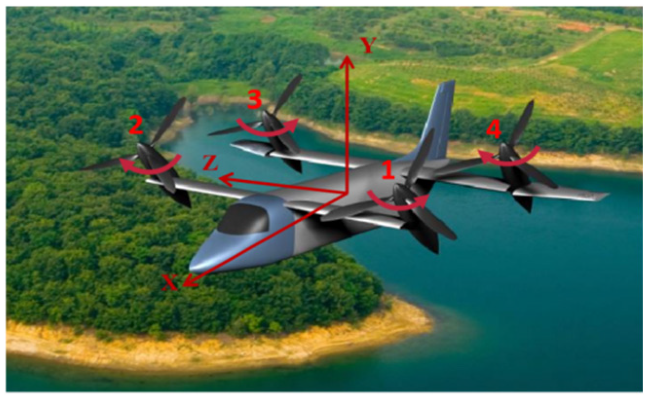
Figure 1. The structure layout of the QTRV.
Drones 08 00560 g001
Figure 2. Change curve of weight coefficient.
Drones 08 00560 g002
Figure 3. The vehicle-mounted test system.
Drones 08 00560 g003
Figure 4. The vehicle-mounted QTRV.
Drones 08 00560 g004
Figure 5. Low-speed and high-speed boundary measurement.
Drones 08 00560 g005
Figure 6. QTRV tilt corridor.
Drones 08 00560 g006
Figure 7. Designed optimal tilt route.
Drones 08 00560 g007
Figure 8. Optimal tilt route calculation flow.
Drones 08 00560 g008
Figure 9. ADRC structure.
Drones 08 00560 g009
Figure 10. ANN-ADRC structure.
Drones 08 00560 g010
Figure 11. QTRV trajectory-tracking control system.
Drones 08 00560 g011
Figure 12. The weight coefficients of different change rules.
Drones 08 00560 g012
Figure 13. Altitude-tracking results.
Drones 08 00560 g013
Figure 14. Altitude-tracking errors.
Drones 08 00560 g014
Figure 15. QTRV HIL system.
Drones 08 00560 g015
Figure 16. Three-dimensional trajectory-tracking results and errors regarding stability and robustness.
Drones 08 00560 g016
Figure 17. Stability and robustness simulation results.
Drones 08 00560 g017aDrones 08 00560 g017b
Figure 18. Three-dimensional trajectory-tracking results and errors regarding disturbance rejection.
Drones 08 00560 g018
Figure 19. Disturbance rejection simulation results.
Drones 08 00560 g019aDrones 08 00560 g019b
Table 1. The main structural parameters of the QTRV.
ParameterValueParameterValue
Weight/kg120Rotor radius/m0.7
Rotor speed/rpm1600Rotor solidity0.075
Number of rotor blades3Front wingspan/m2.0
Average chord length of wing/m0.45Rear wingspan/m3.0
Table 2. Manipulation strategies in different flight modes.
Flight ModesHelicopterFixed-Wing
Heading channelLongitudinal cyclic pitch differentialRudder
Lateral channelLeft and right rotor collective pitch differentialLeft and right aileron differential
Longitudinal channelFront and rear rotor collective pitch differentialFront and rear aileron differential
Vertical channelRotor collective pitch linkageFront and rear ailerons and rotor collective pitch linkage
Disclaimer/Publisher’s Note: The statements, opinions and data contained in all publications are solely those of the individual author(s) and contributor(s) and not of MDPI and/or the editor(s). MDPI and/or the editor(s) disclaim responsibility for any injury to people or property resulting from any ideas, methods, instructions or products referred to in the content.