Abstract
As unmanned aerial vehicles (UAVs) are widely used in various fields, there is an increasing demand for UAV anti-jamming, multipath mitigation, and covert secrecy. Frequency-hopping binary offset carrier (FH-BOC) signals possess higher anti-jamming and multipath mitigation capabilities than direct-sequence spread spectrum (DSSS) and binary offset carrier (BOC) signals. A prerequisite for constructing communication links between UAVs using FH-BOC signals is the design of efficient acquisition algorithms to capture the signals successfully. In this paper, the modulation and characteristics of the FH-BOC signal are introduced. The maximum relative velocity between UAVs is 5.5 km/s, the maximum acceleration is 50 g, and the maximum plus acceleration is 20 g/s. In this high dynamic environment, the parameters for the parallel code phase and Partial Matched Filter–Fast Fourier Transform (PMF-FFT) acquisition algorithms targeting FH-BOC(10,1) signals are designed, and the acquisition performance of these algorithms is comparatively analyzed. The acquisition time for the first and second algorithms is 4.3317 s and 6.137 s. The number of real additions required by the first and second algorithms is approximately and , and the number of real multiplications is approximately and . This helps in selecting the acquisition algorithm when FH-BOC signals are used to build inter-UAV communication links.
1. Introduction
Due to their low cost, flexible design, maneuverability, and suitability for harsh environments, UAVs are widely used in agriculture, rescue, smart cities, and military missions [,]. In some special environments, it is necessary to ensure that the communication signals between UAVs have the characteristics of excellent anti-interference, multipath mitigation, and difficult-to-detect signals. Orthogonal frequency division multiplexing (OFDM) and DSSS signals are commonly used as communication link signals between UAVs []. Although DSSS has the disadvantage of lower data rates compared to OFDM, DSSS has many great advantages when faced with missions with strong interference, multipath effects, and the need for stealth and secrecy. However, Ref. [] compares and analyzes UAV communication systems with OFDM-MIMO and DSSS technologies, pointing out that communication systems with DSSS signals have stronger anti-jamming and energy stealth while providing data transmission rates of up to 10 Mbit/s. Ref. [] indicates that UAV communication channels with data up to 150 Mbit/s can be constructed using the DSSS technique at ranges of more than 100 km while significantly increasing the energy secrecy of the signal. When the global navigation satellite system (GNSS) signal is weak in the environment, the UAV can achieve inter-UAV position measurement by camera, lidar, and ultra-wideband ranging equipment [,]. DSSS modulation allows for an integrated communication and measurement design, providing the possibility of relative position measurement within environments with weak GNSS signals.
When the BOC and DSSS signals have the same spreading code rate, the primary peak of the autocorrelation function (ACF) of the BOC signal is steeper, which signifies that the BOC signal is better capable of rejecting the interference of the multipath effect []. However, Ref. [] points out that the ACF will have one major peak and numerous subpeaks when using the direct acquisition algorithm to capture the BOC signal, and the side peaks will lead to false signal acquisition. Existing acquisition algorithms for BOC signals are designed to mitigate the ACF peak ambiguity. The classical algorithms’ BPSK-like acquisition, subcarrier phase pair cancellation (SCPC), and Autocorrelation Side-Peak Cancellation Technique (ASPeCT) used to capture the BOC signals have some drawbacks [,,,,,]. Ref. [] proposes the FH-BOC modulation system, which has an excellent main–side-peak rejection ratio of ACF, excellent cross-correlation, and a power spectral density (PSD) function similar to the band-pass white noise PSD function. This means that FH-BOC signals have better anti-jamming, multipath mitigation, signal concealment, and counter-surveillance capabilities than the BOC signal with the same bandwidth. Ref. [] states that FH-AltBOC modulation possesses many of the characteristics of AltBOC modulation, and FH-AltBOC() provides a better tracking capability and lower ACF peak ambiguity than AltBOC(). Ref. [] indicates that the ACF peak ambiguity for ACE-FHBOC is lower compared to ACE-BOC. It also demonstrates superior performance in narrowband interference suppression and multipath mitigation compared to ACE-BOC. Figure 1 shows that compared with DSSS and BOC signals, FH-BOC signals have a PSD that is submerged under white noise and a sharp ACF, which means that FH-BOC signals have excellent anti-interference, multipath mitigation performance, and characteristics of signals that are not easily detected. Thus, the FH-BOC signal is able to construct the communication links between UAVs, and at the same time has the potential of relative position measurement between UAVs.
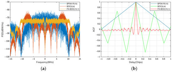
Figure 1.
The PSDs and ACFs of FH-BOC(10,1), BOC(6,4), and BPSK-R(10) signals with bandwith of approximately 20MHz. (a) The PSDs of FH-BOC(10,1), BOC(6,4), and BPSK-R(10) signals. (b) The ACFs of FH-BOC(10,1), BOC(6,4), and BPSK-R(10) signals.
However, the FH-BOC modulation system is particularly novel, and algorithms for capturing FH-BOC signals are just beginning to be explored. Research on fast acquisition algorithms for highly dynamic signals has been carried out for a long time. Refs. [,,] indicate that the parallel code phase acquisition algorithm is computationally more efficient than the serial search algorithm. Ref. [] proposes an acquisition algorithm combining the partial matched filter (PMF) with the FFT (PMF-FFT) and improves the scallop loss of the PMF-FFT acquisition algorithm by complementary zeros and adding windows. Refs. [,,] further improve this loss by adding windows. Ref. [] proposes the PMF length selection criterion. Ref. [] improves the PMF-FFT algorithm by increasing its frequency search coverage, and Ref. [] improves it further by increasing its acquisition speed.
Because the FH-BOC signal has excellent anti-interference and multipath mitigation abilities, it was selected to build communication links between UAVs in this study. However, research on FH-BOC signals still focuses on modulation methods and signal characteristics, and there has been no research on acquisition algorithms for FH-BOC signals. The definition of high dynamics is presented in detail. The maximum relative velocity between UAVs is 5.5 km/s, the maximum acceleration is 50 g, and the maximum plus acceleration is 20 g/s. In this high dynamic environment, the parameters of the parallel code phase and PMF-FFT acquisition algorithms were designed for capturing the FH-BOC(10,1) signal. Meanwhile, the scallop loss from the PMF-FFT algorithm was improved by adding to the amount of data processed by the FFT. The manifestations for the parallel code phase and PMF-FFT algorithms for capturing the FH-BOC(10,1) signal were compared and analyzed from the design complexity, acquisition accuracy, acquisition sensitivity, computational complexity, and acquisition time.
This section provides an introduction. In Section 2, the FH-BOC modulation system is introduced and then the principles for the two algorithms are presented. In Section 3, the parameters of both algorithms are designed in detail and the FH-BOC(10,1) signal is captured. In Section 4, the design complexity, acquisition accuracy, acquisition sensitivity, computational complexity, and single acquisition time of the two algorithms are compared and analyzed. In Section 5, the problems solved by the manuscript and the acquisition performance of the two algorithms are first summarized; secondly, the rationale for selecting the two algorithms, the factors affecting the two algorithms and the limitations of the two algorithms are discussed; finally, the application of the findings in the field and possible future research directions are highlighted.
2. Principles of Modulation and Acquisition Algorithms
In this section, the signal model, baseband signal waveform, ACF, and PSD function of the FH-BOC modulation are described, and then the principles and threshold settings of the two algorithms are presented.
2.1. FH-BOC Modulation
2.1.1. Signal Model
The mathematical expression for FH-BOC modulation is defined as []
where stands for the data code, the spread spectrum code can be symbolized by , represents a frequency-hopping subcarrier, denotes the frequency of the frequency-hopping subcarrier where the k-th spread spectrum code is located, and the duration of the spreading code slice is . In addition, the subcarrier phase of the FH-BOC-modulated signal has sinusoidal and cosine phases. Thus, is expressed as Equation (2):
The frequency-hopping rules of the subcarrier are described below in more detail. is the set of all frequencies of the subcarrier, which is an arithmetic sequence. The common difference in this set is denoted by . stands for the minimum frequency point in this set. The maximum frequency of the subcarrier is represented by . M indicates the quantity of elements in this set. is the subcarrier switching frequency. A frequency-hopping pattern is formed by selecting frequency-hopping points according to certain rules in the frequency-hopping rate set. denotes the pseudo-code rate. denotes the reference frequency value, MHz; ; ; ; ; ; and , where . To ensure subcarrier phase continuity, is an integer multiple of . Referring to the simplified representation of the BOC signal, the expression FH-BOC() is used to denote the FH-BOC signal. When , the FH-BOC signal is abbreviated to FH-BOC(). The mathematical expression for FH-BOC modulation can be succinctly expressed as
2.1.2. Time-Domain Waveform
The data code, the spreading code, and the subcarrier together compose the baseband signal of the FH-BOC modulation system, and these waveforms are presented in Figure 2:

Figure 2.
The time-domain waveform of the baseband signal of the FH-BOC(10,1) signal. Where represents the spread spectrum data code.
Figure 3 demonstrates the variation rule of the subcarrier frequency point of the FH-BOC(10,1) signal:
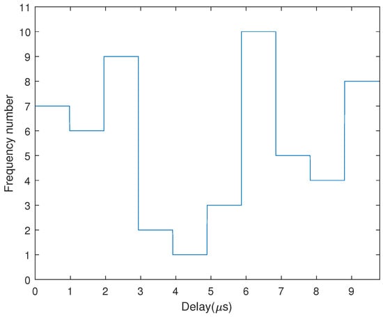
Figure 3.
The subcarrier frequency-hopping pattern of the FH-BOC(10,1) signal.
2.1.3. Autocorrelation Function
The ACF of the FH-BOC signal is []
where denotes the total number of times that the i-th frequency of the subcarrier is used. is the sum of the number of times that each frequency point of the subcarrier is used. The ACF of the subcarrier with the frequency of the i-th hopping point can be represented by (). As the frequency of the subcarrier is fixed during the duration of a spreading code slice, denotes the subcarrier of the BOC signal with frequency . Furthermore, the ACF of the FH-BOC modulated signal is
The phase of BOC signals can be categorized into sinusoidal and cosine phases. The expression for the ACF of a sinusoidal-phase BOC signal is []
The ACF of the BOC signal with a cosine phase is
where stands for the round-down function. represents a triangular pulse of duration , which is
where is half of the period lasted by the subcarrier of the BOC signal, and it can be denoted as
where N is the modulation order, which is double the number of subcarrier cycles used in one spreading code duration, defined as
Substituting Equation (6) into Equation (5), the ACF of the FH-BOC signal with a sinusoidal phase can be calculated as
Substituting Equation (7) into Equation (5), the ACF of the FH-BOC signal with a cosine phase can be computed as
where is twice the number of subcarrier cycles with frequency point i in the duration of a spread spectrum code chip, . is the duration of half a cycle of the subcarrier with frequency i, .
The first point where the main peak of the ACF of the FH-BOC signal with a sinusoidal phase is equal to zero can be denoted as :
The first point where the main peak of the ACF of the FH-BOC signal with a cosine phase is equal to zero can be approximated as
The first zero crossing of the ACF of a sinusoidal-phase BOC signal is given as follows:
The ACFs of the sinusoidally phased FH-BOC(10,1) signal and BOC(5.5,1) signal are presented in Figure 4:
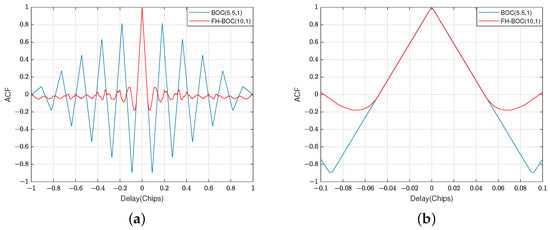
Figure 4.
The ACFs of the sinusoidally phased FH-BOC(10,1) signal and BOC(5.5,1) signal. (a) Illustrates the ACFs of the two signals within code slices of the pseudo-code delay. (b) Illustrates the ACFs of the two signals within code slices of the pseudo-code delay.
The first zero crossing of the ACF of the sinusoidal-phase FH-BOC(10,1) is . When , the main peaks of the ACF for the FH-BOC and BOC signals with a sinusoidal phase strictly overlap in the non-negative part. As shown above, the positive part of the ACF main lobe of the sinusoidal FH-BOC(10,1) strictly overlaps with that of the sinusoidal BOC(5.5,1). This indicates that the variation in accuracy of the sinusoidal FH-BOC(10,1) signal is comparable to that of the sinusoidal BOC(5.5,1) signal. Compared to the BOC signal, the FH-BOC signal has superior main-to-side-peak suppression ratios in their ACF, which reduces the probability of errors in signal capture.
The FH-BOC modulation system has good cross-correlation characteristics. The normalized cross-correlation results of FH-BOC(10,1) and BPSK-R(1), and BOC(5.5,1) and FH-BOC(31,1) are shown in Figure 5, respectively:
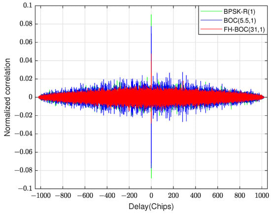
Figure 5.
The normalized cross-correlation results of FH-BOC(10,1) and BPSK-R(1), and BOC(5.5,1) and FH-BOC(31,1).
2.1.4. Power Spectral Density Function
The PSD of the sinusoidal-phase FH-BOC signal is expressed as []
The PSD of the cosine-phase FH-BOC modulated signal is expressed as
The dominant bandwidth of the PSD of the FH-BOC signal with a sinusoidal phase is
The PSDs of the FH-BOC(10,1) and FH-BOC(31,1) signals with a sinusoidal phase are shown in Figure 6:
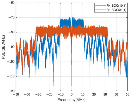
Figure 6.
The PSDs of the FH-BOC(10,1) and FH-BOC(31,1) signals with a sinusoidal phase.
2.2. Principle of Acquisition Algorithms
2.2.1. Parallel Code Phase Acquisition Algorithm
The core principle of the algorithm is that the mutual correlation value of the two periodic sequences can be calculated by a Fourier inverse transform based on the frequency-domain product result. and are periodic sequences with length N, and their normalized correlation value can be expressed as
The correlation value is discrete-Fourier-transformed to obtain :
where the discrete Fourier transforms of and are taken to obtain and , respectively. is obtained from by conjugate computation. The algorithmic process is visualized in Figure 7 [].
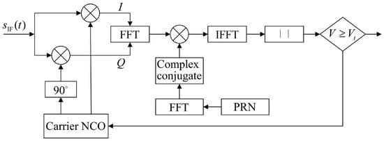
Figure 7.
Parallel code phase acquisition algorithm.
The single acquisition probability and the false alarm probability are, respectively,
where the probability density function (PDF) of the detected quantity without a signal is denoted by . When the signal is present, is the PDF of the detection quantity, and the envelope of the detection quantity obeys the Rayleigh distribution:
The detection threshold can be expressed as
2.2.2. PMF-FFT Acquisition Algorithm
The PMF-FFT acquisition algorithm uses FFT to make the two-dimensional search in the pseudo-code phase and Doppler frequency into a one-dimensional search in the pseudo-code phase, and uses multiple PMFs to reduce the integration time used to search a pseudo-code phase. The sampling frequency is , and one pseudo-code period is T. Therefore, the number of sampling points in a pseudo-code period is . The number of PMFs is P and the length of the PMF is X, and then (). When the received signal is demodulated, it will be equally divided into P parts, and in order to prevent the length of the last PMF being inconsistent with the lengths of the other PMFs, it is necessary to perform the first complementary zeros, and the number of complementary zeros is . The function of the PMF is to partially despread the demodulated signal, and the outputs of the PMFs are partially correlated results. The Doppler frequency estimate can be calculated by performing an N-point FFT operation on the P results. The process diagram of the PMF-FFT acquisition algorithm is shown in Figure 8:
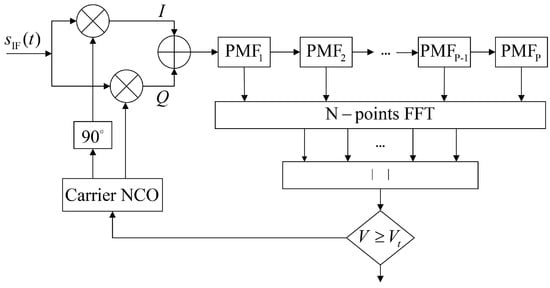
Figure 8.
PMF-FFT acquisition algorithm.
The IF signal received by the receiver is shown in Equation (25) []:
where the pseudo-code can be denoted by . is the Doppler frequency and the sampling time interval can be expressed as . The output of the n-th () PMF is
where K denotes the offset of the pseudo-code sequence. When the phases of both the received signal and the spreading code at the receiver are synchronized, , Equation (26) simplifies to
can be abbreviated as
where is the frequency response for the PMF and is that for the FFT.
The frequency search accuracy of the PMF-FFT acquisition algorithm is
When the search frequency is an integer multiple of half of , there is a maximum scallop loss:
The bandwidth of the PMF-FFT acquisition algorithm is
To ensure that the signal energy loss is not too large, a 1/4 of the first zero-crossing point is generally taken as the actual frequency acquisition range.
This algorithm suffers from the disadvantages of low frequency search accuracy and small Doppler frequency search range. T is the duration of a pseudo-code cycle, usually . When , the frequency search accuracy is
To improve the frequency search accuracy, the P PMFs results are zero-complemented with zeros. The frequency search accuracy can be made to be no greater than 500 Hz by setting the appropriate N. The frequency search range is
To improve the frequency search range, the number of PMFs can be increased. When P is larger, the length X of the PMFs is smaller. According to Equation (32), the frequency search accuracy meets the requirement and no additional zeros are needed to increase N.
The false alarm rate for a single detection can be defined as [,]
When the signal is absent, is the PDF of the detection quantity, and the envelope of the detection quantity obeys the Rayleigh distribution:
The distribution function of the Rayleigh function is
The false alarm rate of the single-point FFT output is as follows:
The distributions for the N-point FFT outputs are identical and uncorrelated with each other, so the false alarm rate of the PMF-FFT algorithm is as follows:
The detection threshold can be expressed as
3. Experimental Results
To increase the number of signal frequency-hopping points and make the hardware complexity appropriate, the maximum frequency of the subcarrier is 10.23 MHz. To improve the anti-interference and anti-interception performance of the signal, the minimum frequency and frequency-hopping interval of the subcarrier is 1.023 MHz. Therefore, the FH-BOC(10:1:1,1,1) signal with a sinusoidal phase, which is abbreviated as FH-BOC(10,1), is chosen as the subject of this study. High dynamics is defined as a relative velocity of the receiver greater than 1 and an acceleration of not less than 4×g. Therefore, the relative motion state between UAVs is defined, and the corresponding maximum Doppler frequency is 587 kHz. The RF frequency of the signal is 32 GHz, and the Doppler frequency search range is [, +600 ] for the highly dynamic signal in the Ku-band. In order to simulate an arbitrary distance between UAVs, the pseudo-code phase search range is ]. The detailed experimental parameters are shown in Table 1.

Table 1.
Simulation parameters.
In this paper, the direct digital frequency synthesis technique is used to generate pseudo-codes, frequency-hopping subcarriers, and IF carriers. The baseband signal is obtained by multiplying the pseudo-code and the subcarrier, and the bandwidth of the signal is 22.506 MHz. Then, the IF signal is obtained by multiplying with the IF subcarrier. The center frequency of the IF signal is 35 MHz and the bandwidth is 22.506 MHz.
3.1. Parallel Code Phase Acquisition Algorithm
The frequency search step that is set in the parallel code phase algorithm is 500 Hz. In order to satisfy the FFT operation points of two integer powers and the minimum number of operation points, the down-sampling frequency is 32.768 MHz. The bandwidth of the low-pass filter is 22.5065 MHz and the threshold is . The detailed design for the algorithm is shown in Figure 9:
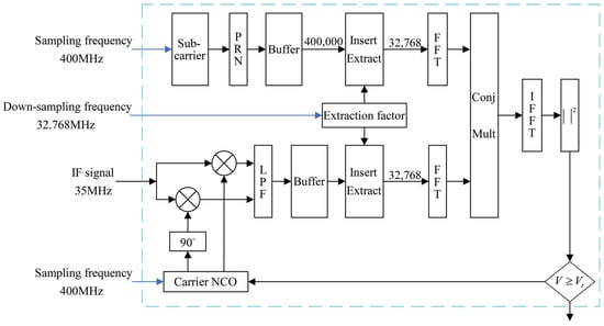
Figure 9.
The detailed design of the parallel code phase acquisition algorithm.
The velocity is set to 3 , the acceleration is set to 40 , and the plus acceleration is set to 20 , corresponding to a Doppler frequency of 320,043 Hz. The code offset is set to 500.225 code slices. When the SNR is 0 and −25 dB, the acquisition frequency for the FH-BOC(10,1) signal is 320,000 Hz and the acquisition phase is 500.214 code slices. The frequency error is 43 Hz and the phase error is 0.011 code slices. When the SNR is 0 and −25 dB, the results applied by the parallel phase acquisition algorithm to capture the FH-BOC(10,1) signal are presented in Figure 10. It also shows that the parallel code phase acquisition algorithm has the ability to successfully capture the FH-BOC(10,1) signal when the SNR is 0 and −25 dB, and the correlation value has no clear attenuation.
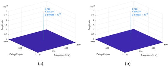
Figure 10.
The results applied by the parallel phase acquisition algorithm to capture the FH-BOC(10,1) signal. (a) Shows the acquisition result when the SNR is 0 dB. (b) Demonstrates the acquisition result when the SNR is −25 dB.
3.2. PMF-FFT Acquisition Algorithm
The first zero-crossing point of the FH-BOC(10,1) signal is about 0.04762 code slices, so the phase search step of the PMF-FFT algorithm is set to 0.0426 code slices. The low-pass filter bandwidth is set to 23.706 MHz. For the purpose of satisfying the Nyquist sampling theorem and ensuring that the last matched filter is no longer zero-complemented, while minimizing the computational effort, the down-sampling frequency is set to 24 MHz. The threshold is set to . To improve the Doppler frequency search range, the number of PMFs was increased. For minimizing the energy loss in the frequency capture range , P is set to 2400. According to Equation (32), the number of data points computed by the FFT is 8192, and the Doppler search accuracy is 292.97 Hz. According to Equation (34), the frequency search scope of the designed PMF-FFT algorithm is calculated to be 2400 . The normalized amplitude-frequency response of the PMF section is shown in Figure 11:
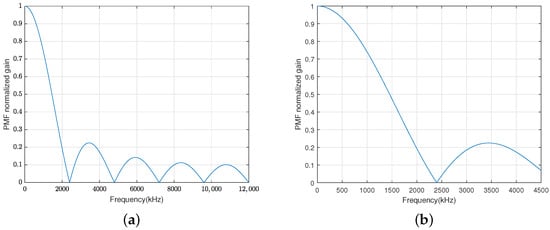
Figure 11.
The normalized amplitude-frequency response of the PMF section. (a) Shows the normalized amplitude-frequency response in [0 kHz, 12,000 kHz]. (b) Shows the normalized amplitude-frequency response in [0 kHz, 4500 kHz].
The maximum PMF-normalized gain attenuation for the Doppler frequency within is about 0.9. The detailed design for the PMF-FFT acquisition algorithm is shown in Figure 12:
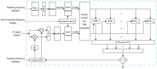
Figure 12.
The detailed design of the PMF-FFT acquisition algorithm.
The velocity is set to 3 , the acceleration is set to 40 , and the plus acceleration is set to 20 , corresponding to a Doppler frequency of 320,043 Hz. The code offset is set to 500.225 code slices. Regardless of whether the SNR is 0 or −25 dB, the acquisition frequency of the PMF-FFT acquisition algorithm for the FH-BOC(10,1) signal is 319,922 Hz, and the acquisition phase is 500.24 code slices. The frequency error is 121 Hz and the phase error is 0.015 code slices. When the SNR is 0 and −25 dB, the resulting figures for the PMF-FFT algorithm are shown in Figure 13. It also demonstrates that the PMF-FFT acquisition algorithm has the ability to successfully capture the FH-BOC(10,1) signal when the SNR is 0 and −25 dB, and the correlation value has no clear attenuation.
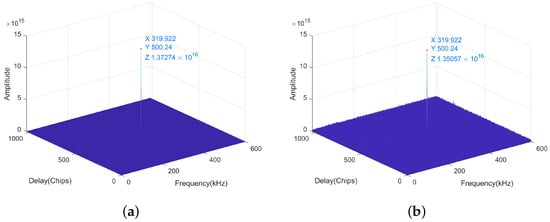
Figure 13.
The results applied by the PMF-FFT acquisition algorithm to capture the FH-BOC(10,1) signal. (a) Shows the acquisition result when the SNR is 0 dB. (b) Demonstrates the acquisition result when the SNR is −25 dB.
4. Performance Comparison Analysis
The algorithm design complexity, acquisition accuracy, acquisition sensitivity, computational complexity, and acquisition time of the two algorithms are compared and analyzed.
4.1. Design Complexity Analysis
The parallel code phase acquisition algorithm involves determining the frequency search step, the down-sampling frequency, and the threshold value. For a classical tracking loop, the frequency search step is usually set to 500 Hz. The minimum down-sampling frequency can be determined according to the maximum frequency of the baseband signal and frequency search step. Then, the down-sampling frequency can be determined according to the FFT points that need to satisfy the integer power of 2. Based on the false alarm rate, the judgment threshold of the detection is calculated.
The PMF-FFT acquisition algorithm needs to determine the phase search step, the down-sampling frequency, the number of PMFs, the amount of data to be processed by the PMF, the amount of data to be handled by the FFT, and the threshold value. The phase search step can be designed according to the first zero-crossing point of the ACF. According to the maximum frequency of the baseband signal, the maximum Doppler frequency tolerance of the tracking loop, and the Nyquist sampling theorem, the smallest sampling frequency is determined. Based on the Doppler frequency capture range, the length of the PMF can be determined from Equation (35). Based on the down-sampling frequency and the integration time, the number of PMFs can be determined. At this point, the amount of data processed by all matched filters may be larger than the total amount of data; thus, it is necessary to zero-compensate the last matched filter or adjust the down-sampling frequency upwards. Based on the maximum Doppler frequency tolerance of the tracking loop, the number of points for FFT calculation can be determined from Equation (33). The threshold value can be calculated from Equation (43).
The parameter design of the PMF-FFT acquisition algorithms is interdependent. The length of the PMF and the down-sampling frequency jointly determine the Doppler frequency acquisition range. When the down-sampling frequency is determined, the shorter the length of the PMF, the larger the range of Doppler frequency acquisition. However, to meet the acquisition accuracy requirement, the amount of data processed by the FFT will increase. The PMF-FFT acquisition algorithm is restricted between the acquisition time and resource consumption. The shorter the length of the PMF, the shorter the acquisition time, but the higher the number of PMFs, the higher the implementation complexity. Therefore, the PMF-FFT acquisition algorithm requires a trade-off in design parameters.
4.2. Analysis of Acquisition Accuracy
Velocity is randomly selected within , acceleration is randomly selected within , additive acceleration is randomly selected within , and the code phase is randomly selected within code slices. In 100 repeated simulations when the SNR is 0 and −25 dB, the phase errors are shown in Figure 14:
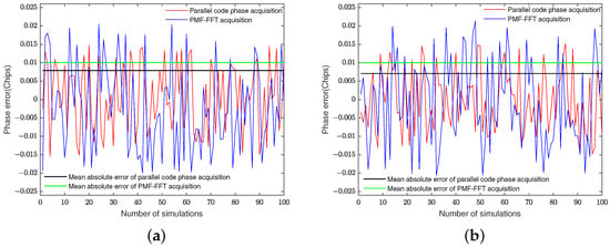
Figure 14.
The phase errors and mean absolute error of the two algorithms in 100 repeated simulations. (a) Shows the phase errors and mean absolute error when the SNR is 0 dB. (b) Demonstrates the phase errors and mean absolute error when the SNR is −25 dB.
The theoretical phase accuracy of the parallel code phase acquisition algorithm is 0.0312 code chips and the maximum phase error is 0.0156 code chips. The theoretical phase error is uniformly distributed within code chips and the average absolute phase error is 0.0078 code chips. In 100 repeated simulations with SNR = 0 and , the phase errors are distributed within and code slices, the maximum phase errors are 0.0155 and 0.0152 code slices, and the mean absolute phase errors are 0.0079 and 0.0071 code slices, which are slightly higher and lower than the theoretical values, respectively.
The theoretical phase accuracy of the PMF-FFT acquisition algorithm is 0.0426 code chips and the maximum phase error is 0.0213 code chips. The theoretical phase error is uniformly distributed within code chips and the average absolute phase error is 0.0106 code chips. In 100 repeated simulations with SNR = 0 and −25 dB, the phase errors are distributed within and code slices, the maximum phase errors are 0.0205 and 0.0213 code slices, and the mean absolute phase errors are both 0.01 code slices, respectively, which are both marginally smaller than the theoretical values.
In 100 repeated simulations when the SNR is 0 and −25 dB, the frequency errors are shown in Figure 15:
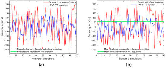
Figure 15.
The frequency errors and mean absolute error of the two algorithms in 100 repeated simulations. (a) Shows the frequency errors and mean absolute error when the SNR is 0 dB. (b) Demonstrates the frequency errors and mean absolute error when the SNR is −25 dB.
The theoretical frequency accuracy of the parallel code phase acquisition algorithm is 500 Hz and the maximum frequency error is 250 Hz. Theoretically, the frequency error is uniformly distributed within and the mean absolute frequency error is 125 Hz. In 100 repeated simulations with SNR = 0 and −25 dB, the frequency errors are distributed within and , the maximum frequency errors are 250 and 248 Hz, and the mean absolute phase errors are 131.67 and 122.8 Hz, which are marginally larger and smaller than the theoretical values, respectively.
The theoretical frequency accuracy of the PMF-FFT acquisition algorithm is and the maximum frequency error is 146.48 Hz. Theoretically, the frequency error is uniformly distributed within and the mean absolute frequency error is 73.24 Hz. In 100 repeated simulations with SNR = 0 and −25 dB, the frequency errors are distributed within and , the maximum frequency errors are 145.38 and 142.7 Hz, and the mean absolute phase errors are 69.54 and 60.7 Hz, respectively, which are both marginally smaller than the theoretical values.
In summary, the phase error of the parallel code phase acquisition algorithm is smaller than that of the PMF-FFT acquisition algorithm in both theoretical design and simulation results. However, the frequency error of the former algorithm is larger than that of the latter in both theoretical design and simulation results. When the SNR changes from 0 to −25 dB, the accuracy of the two algorithms does not decrease significantly.
4.3. Sensitivity Analysis
The maximum frequency error of the parallel code phase acquisition algorithm is , and the loss in SNR due to the Doppler frequency offset can be expressed as
where the residual Doppler frequency can be denoted by . The sampling interval can be expressed as , and N is the number of sampling points in one pseudo-code period. can be calculated from Equation (44).
The maximum phase error of the parallel code phase acquisition algorithm is 0.0156 code slices. The maximum loss caused by the code slices not being perfectly aligned is
dB can be calculated from Equation (45).
The maximum SNR loss present in the parallel code phase acquisition algorithm is about −4.3394 dB.
The PMF-FFT acquisition algorithm suffers from a correlation loss, which results from the partial matched filtering and is dependent on the Doppler frequency and the matched filter length. The correlation loss is denoted as []
The maximum correlation loss can be calculated as dB from Equation (46) and the correlation loss map is shown in Figure 16:
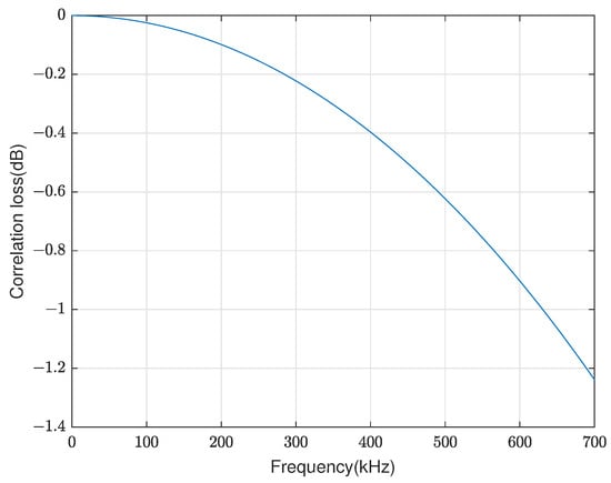
Figure 16.
Correlation loss of the PMF-FFT acquisition algorithm.
The PMF-FFT acquisition algorithm suffers from scallop loss, which is determined by the Doppler frequency. The scallop loss is maximized once the Doppler frequency is equal to the frequency between the two FFT points. The maximum scallop loss is
The maximum scallop loss = −0.3088 dB can be calculated from Equation (47).
The maximum phase error of the PMF-FFT acquisition algorithm is 0.0228 code slices, and the maximum loss caused by the unaligned code slices is
dB can be calculated from Equation (48).
The maximum SNR loss of the PMF-FFT acquisition algorithm is about −6.3526 dB.
The single acquisition probability of the two acquisition algorithms at different SNRs is demonstrated in Figure 17:
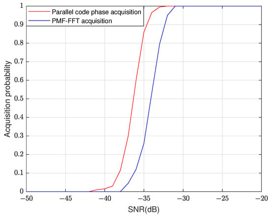
Figure 17.
Single acquisition probability of the two algorithms at different SNRs.
Theoretically, the parallel code phase acquisition algorithm is 2.0132 dB more sensitive than the PMF-FFT acquisition algorithm. When the single acquisition probability is 0.9, the SNR difference between the two algorithms is about 2.29 dB, which is approximately the same as the theoretical value.
4.4. Computational Complexity Analysis
The frequency search step that is set in the parallel code phase algorithm is 500 Hz and the Doppler frequency search range is . Therefore, the frequency search number is 2401. The parallel code phase acquisition algorithm needs two Fourier transforms, one multiplication of the complex sequence with length N, one inverse Fourier transform, and one modular square operation in each search process. The required numbers of complex multiplications and additions for FFT transformations of length N points are, respectively [],
There are 32,768 points for each FFT calculation, and the quantities of complex multiplications and additions for two FFT and one IFFT operations in a frequency search are, respectively,
The number of complex multiplications required for a complex multiplication of length 32,768 is
The total quantity of complex multiplications and additions per frequency search are, respectively,
The squaring operation of a complex number of length N requires two real operations and one real addition; hence,
Four real-number multiplication operations and two number addition operations are involved in a complex multiplication operation. Meanwhile, two real-number addition operations are involved in a complex addition operation. Therefore, the total numbers of real-number multiplications and additions are, respectively,
The parallel code phase acquisition requires 2401 frequency searches, so there are 7,552,892,928 real multiplications and 10,857,283,584 real additions in total.
The PMF-FFT search algorithm is used for the serial search of spread spectrum code phases. The length of the pseudo-code is 1023 and the pseudo-code phase search step is 0.0426 code slices, so there are 24,015 phase searches. There are 24,000 data points processed in one capture, with a total of 2400 matched filters, each of which has a length of 10 points. A matched filter needs to multiply and accumulate the real and complex numbers of 10 points. The quantities of real multiplications and additions required for a matched filter are, respectively,
One pseudo-code phase search requires one Fourier transform, which processes 8192 points. According to Equations (49) and (50), the numbers of complex multiplications and additions needed for one FFT operation are, respectively,
Four real-number multiplication operations and two number addition operations are involved in a complex multiplication operation. Meanwhile, two real-number addition operations are involved in a complex addition operation. Therefore, the quantities of real multiplications and additions required for the FFT operation are, respectively,
The squaring operation of a complex number of length N requires two real operations and one real addition.
Therefore, the quantities of real multiplications and additions required in one phase search process are, respectively,
The PMF-FFT acquisition algorithm needs to perform 24,015 phase searches, so there are 6,661,184,640 real multiplications and 8,906,683,200 real additions in total.
In summary, there are 7,552,892,928 real multiplications and 10,857,283,584 real additions involved in the parallel code phase acquisition algorithm, whereas there are 6,661,184,640 real-number multiplications and 8,906,683,200 real additions needed for the PMF-FFT algorithm. The PMF-FFT algorithm requires about 88.2% of the real multipliers and about 82.1% of the real adders of the parallel code phase acquisition algorithm. The computational complexity of the parallel code phase acquisition algorithm is slightly higher than that of the PMF-FFT algorithm.
4.5. Analysis of Acquisition Duration
The clock cycles required for a single acquisition of the parallel code phase acquisition algorithm are shown in Table 2:

Table 2.
Clock cycle consumption of parallel code phase acquisition algorithm for a single acquisition.
Considering the remaining waiting time in the processing, 100 clock cycles are set as the margin. Therefore, the time necessary for one frequency search is 1.8 ms. There are 2401 frequency searches in total, so the total acquisition time of the parallel code phase acquisition is s.
The clock cycles required by the PMF-FFT acquisition algorithm for a single acquisition are in Table 3:

Table 3.
Clock cycle consumption of PMF-FFT acquisition algorithm for a single acquisition.
Considering the remaining waiting time in the processing, 100 clock cycles are set as the margin. Therefore, the time necessary for one phase search is ms. There are 24,015 phase searches in total, so the total acquisition time of the PMF-FFT acquisition algorithm is s.
The acquisition time of the parallel code phase acquisition algorithm is lower than that of the PMF-FFT acquisition algorithm. The Matlab simulation elapsed time is shown in Figure 18, which can reflect the acquisition time performance of the two algorithms from the side:
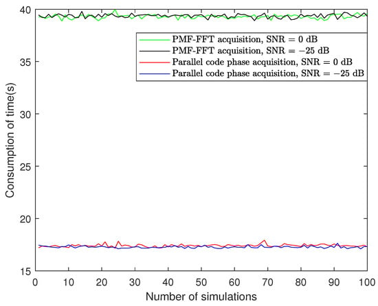
Figure 18.
MATLAB simulation consumption time of the two algorithms with SNR = 0 and −25 dB.
5. Conclusions
To meet the requirements of anti-jamming, multipath mitigation, and signal steganography, the FH-BOC signal is selected to construct the inter-UAV communication link because of its sharper main peak of the ACF and PDF submerged under noise. The motion state of the UAV is illustrated in the paper, and the Doppler frequency search range is since the signal is transmitted in the Ku band. The parameters of the parallel code phase and PMF-FFT acquisition algorithms are designed in detail for the Doppler frequency search range of , and both algorithms successfully capture the FH-BOC(10,1) signal. The theoretical derivation and simulation results of the parameter design, acquisition accuracy, SNR loss, computational complexity, and acquisition time of both algorithms are explained in detail above.
- The parameter design of the parallel code phase acquisition algorithm is simple, and the parameter design of the PMF-FFT acquisition algorithms is interdependent;
- The maximum frequency error of the parallel code phase acquisition algorithm is and the maximum phase error is 0.0156 code chips, whereas those of the PMF-FFT acquisition algorithm are 146.48 Hz and 0.0213 code chips, respectively;
- The SNR loss of the parallel code phase acquisition algorithm is −4.3394 dB and that of the PMF-FFT acquisition algorithm is −6.3526 dB;
- There are 7,552,892,928 real multiplications and 10,857,283,584 real additions involved in the parallel code phase acquisition algorithm, whereas there are 6,661,184,640 real-number multiplications and 8,906,683,200 real additions needed for the PMF-FFT algorithm;
- The acquisition time of the parallel code phase acquisition algorithm is 4.3317 s, whereas that of the PMF-FFT acquisition algorithm is 6.137 s.
Above is a brief summary about the purpose of the manuscript and the results of the manuscript; the design of the experimental parameters and the results of the experiment are discussed as follows:
- Although the two algorithms have their own advantages and disadvantages in the accuracy of phase and frequency acquisition, they do not affect the tracking loop;
- Despite the disadvantage of SNR loss in the PMF-FFT acquisition algorithm, the parallel code phase acquisition algorithm for the FH-BOC signal has 2.0132 dB less SNR loss than the PMF-FFT acquisition algorithm;
- Although the PMT-FFT algorithm has relatively lower computational complexity and longer acquisition time than the parallel code phase algorithm, it needs to be addressed that these do not limit the use in highly dynamic and real-world UAV applications;
- The increase in the frequency search range will lead to the number of phase searches in the parallel code phase acquisition algorithm increasing.To increase the frequency search range of the PMF-FFT acquisition algorithm, the number of PMFs will be increased, which increases the difficulty of hardware implementation;
- Compared with the BPSK signal, the bandwidth of the FH-BOC signal is larger, which will lead to an increase in the amount of data processed during the integration time;
- The smaller the first over-zero point of the ACF will lead to an increase in the number of phase searches in the PMF-FFT acquisition algorithm. Therefore, the algorithm will not be suitable for FH-BOC signals with large ;
- The larger the bandwidth of the FH-BOC signal, the larger the amount of data computed by the FFT, which may exceed the limitations of the FFT IP core.
To build a communication link between UAVs using FH-BOC signals, designing an efficient acquisition algorithm is fundamental. In this paper, the parallel code phase and PMF-FFT acquisition algorithms are designed in detail, and the acquisition performance of the two algorithms is compared to provide a measure for designing suitable acquisition algorithms under different requirements. The FH-BOC signal has excellent anti-jamming and multipath mitigation performance, and future UAVs using the FH-BOC signal to build communication links can be used in agriculture, warfare, marine and other fields. Neither the parallel code phase nor the PMF-FFT acquisition algorithm can be used to capture FH-BOC signals when is particularly large, so redesigning the algorithm to break through the constraints of the two algorithms is one of the future research directions. Secondly, the design of more advanced and excellent acquisition algorithms to capture FH-BOC signals is also a future research direction.
Author Contributions
Conceptualization, X.L. and Y.Z.; methodology, P.Z.; software, P.Z.; validation, X.L. and L.W.; formal analysis, P.Z.; investigation, P.Z.; resources, P.Z.; data curation, P.Z.; writing—original draft preparation, P.Z.; writing—review and editing, X.L. and P.Z.; visualization, P.Z. and S.Z. All authors have read and agreed to the published version of the manuscript.
Funding
This research was funded by the National Key R&D Program of China (No. 2021YFB3900300).
Data Availability Statement
Data are contained within the article.
Conflicts of Interest
The authors declare no conflicts of interest.
Abbreviations
The following abbreviations are used in this manuscript:
| UAV | Unmanned Aerial Vehicle |
| DSSS | Direct Sequence Spread Spectrum |
| FH-BOC | Frequency-Hopping Binary Offset Carrier |
| BOC | Binary Offset Carrier |
| ACF | Autocorrelation Function |
| PSD | Power Spectral Density |
| PMF-FFT | Partial Matched Filter-Fast Fourier Transform |
| OFDM | Orthogonal Frequency Division Multiplexing |
| GNSS | Global Navigation Satellite System |
| SCPC | Subcarrier Phase Cancellation |
| ASPeCT | Autocorrelation Side-peak Cancellation Technique |
| PMF | Partial Matched Filter |
| Probability Density Function |
References
- Hooshyar, M.; Huang, Y.M. Meta-heuristic Algorithms in UAV Path Planning Optimization: A Systematic Review (2018–2022). Drones 2023, 7, 687. [Google Scholar] [CrossRef]
- Noor, F.; Khan, M.A.; Al-Zahrani, A.; Ullah, I.; Al-Dhlan, K.A. A Review on Communications Perspective of Flying Ad-Hoc Networks: Key Enabling Wireless Technologies, Applications, Challenges and Open Research Topics. Drones 2020, 4, 65. [Google Scholar] [CrossRef]
- Chirov, D.S.; Kandaurova, E.O. Research of Broadband Signals for the Organization of a Communication Channel with UAVs. In Proceedings of the 2024 Systems of Signal Synchronization, Generating and Processing in Telecommunications (SYNCHROINFO), Vyborg, Russia, 1–3 July 2024; pp. 1–4. [Google Scholar]
- Chirov, D.S.; Chertova, O.G.; Lobov, E.M.; Bazylev, M.V. Construction of a Communication Channel with UAVs Based on Direct Sequence Spread Spectrum Signals. In Proceedings of the 2024 Systems of Signals Generating and Processing in the Field of on Board Communications, Moscow, Russia, 12–14 March 2024; pp. 1–4. [Google Scholar]
- Wang, R.; Deng, Z. Rapid Initialization Method of Unmanned Aerial Vehicle Swarm Based on VIO-UWB in Satellite Denial Environment. Drones 2024, 8, 339. [Google Scholar] [CrossRef]
- Hou, C.; Liu, W.; Tang, H.; Cheng, J.; Zhu, X.; Chen, M.; Gao, C.; Wei, G. Non-Line-of-Sight Positioning Method for Ultra-Wideband/Miniature Inertial Measurement Unit Integrated System Based on Extended Kalman Particle Filter. Drones 2024, 8, 372. [Google Scholar] [CrossRef]
- Betz, J.W. Binary offset carrier modulations for radionavigation. Navigation 2001, 48, 227–246. [Google Scholar] [CrossRef]
- Julien, O.; Macabiau, C.; Cannon, M.E.; Lachapelle, G. ASPeCT: Unambiguous sine-BOC (n, n) acquisition/tracking technique for navigation applications. IEEE Trans. Aerosp. Electron. Syst. 2007, 43, 150–162. [Google Scholar] [CrossRef]
- Burian, A.; Lohan, E.S.; Renfors, M. BPSK-like methods for hybrid-search acquisition of Galileo signals. In Proceedings of the 2006 IEEE International Conference on Communications, Istanbul, Turkey, 11–15 June 2006; Volume 11, pp. 5211–5216. [Google Scholar]
- Lohan, E.S. Statistical analysis of BPSK-like techniques for the acquisition of Galileo signals. J. Aerosp. Comput. Inf. Commun. 2006, 3, 234–243. [Google Scholar] [CrossRef][Green Version]
- Heiries, V.; Roviras, D.; Ries, L.; Calmettes, V. Analysis of non ambiguous BOC signal acquisition performance. In Proceedings of the 17th International Technical Meeting of the Ssatellite Division of the Institute of Navigation (ION GNSS 2004), Long Beach, CA, USA, 21–24 September 2004; pp. 2611–2622. [Google Scholar]
- Yang, Z.; Huang, Z.; Geng, S. Unambiguous acquisition performance analysis of BOC (m, n) signal. In Proceedings of the 2009 International Conference on Information Engineering and Computer Science, Wuhan, China, 19–20 December 2009; pp. 1–4. [Google Scholar]
- Wen, L.; Yue, X.; Zhongliang, D.; Jichao, J.; Lu, Y. Correlation combination ambiguity removing technology for acquisition of sine-phased BOC (kn, n) signals. China Commun. 2015, 12, 86–96. [Google Scholar] [CrossRef]
- Yao, Z.; Lu, M.; Feng, Z. Unambiguous sine-phased binary offset carrier modulated signal acquisition technique. IEEE Trans. Wirel. Commun. 2010, 9, 577–580. [Google Scholar] [CrossRef]
- Ma, J.; Yang, Y.; Li, H.; Li, J. FH-BOC: Generalized low-ambiguity anti-interference spread spectrum modulation based on frequency-hopping binary offset carrier. GPS Solut. 2020, 24, 70. [Google Scholar] [CrossRef]
- Ma, J.; Yang, Y. A generalized anti-interference low-ambiguity dual-frequency multiplexing modulation based on the frequency-hopping technique. IEEE Access 2020, 8, 95288–95300. [Google Scholar] [CrossRef]
- Ma, J.; Yang, Y.; Ye, L.; Deng, L.; Li, H. Dual-Sideband Constant-Envelope Frequency-Hopping Binary Offset Carrier Multiplexing Modulation for Satellite Navigation. Remote Sens. 2022, 14, 3871. [Google Scholar] [CrossRef]
- Lei, Q.; Lei, L. GPS signal acquisition based on FFT. In Proceedings of the 2010 Second International Conference on Information Technology and Computer Science, Kiev, Ukraine, 24–25 July 2010; pp. 110–113. [Google Scholar]
- Van Nee, D.; Coenen, A. New fast GPS code-acquisition technique using FFT. Electron. Lett. 1991, 2, 158–160. [Google Scholar] [CrossRef]
- Leclere, J.; Botteron, C.; Farine, P.A. Acquisition of modern GNSS signals using a modified parallel code-phase search architecture. Signal Process. 2014, 95, 177–191. [Google Scholar] [CrossRef]
- Spangenberg, S.M.; Scott, I.; McLaughlin, S.; Povey, G.J.; Cruickshank, D.G.; Grant, P.M. An FFT-based approach for fast acquisition in spread spectrum communication systems. Wirel. Pers. Commun. 2000, 13, 27–55. [Google Scholar] [CrossRef]
- Chang, L.; Jun, Z.; Zhu, Y.; Qingge, P. Analysis and optimization of PMF-FFT acquisition algorithm for high-dynamic GPS signal. In Proceedings of the 2011 IEEE 5th International Conference on Cybernetics and Intelligent Systems (CIS), Qingdao, China, 17–19 September 2011; pp. 185–189. [Google Scholar]
- Zeng, C.; Li, W.; Bi, B.; Chen, Q. Comparison and Realization of Fast Acquisition Method for GPS Signal under High Dynamic. MATEC Web Conf. 2017, 108, 15005. [Google Scholar] [CrossRef]
- Pan, Y.; Zhang, T.; Zhang, G.; Luo, Z. Analysis of an improved acquisition method for high-dynamic BOC signal. J. Syst. Eng. Electron. 2016, 27, 1158–1167. [Google Scholar] [CrossRef]
- Wang, X.; Jiang, K.; Chu, R.; Zhang, H.; Wang, C. Research on Acquisition Method of DSSS System Based on PMF-FFT. In Proceedings of the 2023 8th International Conference on Communication, Image and Signal Processing (CCISP), Chengdu, China, 17–19 November 2023; pp. 552–558. [Google Scholar]
- Lu, Z.; Chen, Y.; Jiao, Y.; Sun, K. An Improved PMF-fft acquisition approach based on frequency segmentation for DSSS signals. In Proceedings of the 2021 IEEE 5th Information Technology, Networking, Electronic and Automation Control Conference (ITNEC), Xi’an, China, 15–17 October 2021; Volume 5, pp. 143–147. [Google Scholar]
- Qi, J.; Luo, F.; Song, Q. Fast acquisition method of navigation receiver based on folded PMF-FFT. In Proceedings of the 2014 IEEE Computers, Communications and IT Applications Conference, Vasteras, Sweden, 21–25 July 2014; pp. 62–66. [Google Scholar]
- Li, X.; Zeng, X.; Xue, L. Integrated Communication and Measurement System with BOC-Assisted OFDM. Drones 2023, 7, 14. [Google Scholar] [CrossRef]
- Sun, B.; Zheng, Z.; Zhou, Y.; Zhang, R. Research on fast acquisition algorithm of spread spectrum signal based on PMF-FFT. In Proceedings of the 2022 7th International Conference on Communication, Image and Signal Processing (CCISP), Chengdu, China, 18–20 November 2022; pp. 291–296. [Google Scholar]
- Stirling-Gallacher, R.; Hulbert, A.; Povey, G. A fast acquisition technique for a direct sequence spread spectrum signal in the presence of a large Doppler shift. In Proceedings of the ISSSTA’95 International Symposium on Spread Spectrum Techniques and Applications, Mainz, Germany, 25 September 1996; Volume 1, pp. 156–160. [Google Scholar]
- Grant, P.M.; Spangenberg, S.M.; Scott, I.; McLaughlin, S.; Povey, G.J.; Cruickshank, D.G. Doppler estimation for fast acquisition in spread spectrum communication systems. In Proceedings of the 1998 IEEE 5th International Symposium on Spread Spectrum Techniques and Applications-Proceedings. Spread Technology to Africa (Cat. No. 98TH8333), Sun City, South Africa, 4 September 1998; Volume 1, pp. 106–110. [Google Scholar]
- Zheng, Y. A software-based frequency domain parallel acquisition algorithm for GPS signal. In Proceedings of the 2010 International Conference on Anti-Counterfeiting, Security and Identification, Chengdu, China, 18–20 July 2010; pp. 298–301. [Google Scholar]
Disclaimer/Publisher’s Note: The statements, opinions and data contained in all publications are solely those of the individual author(s) and contributor(s) and not of MDPI and/or the editor(s). MDPI and/or the editor(s) disclaim responsibility for any injury to people or property resulting from any ideas, methods, instructions or products referred to in the content. |
© 2024 by the authors. Licensee MDPI, Basel, Switzerland. This article is an open access article distributed under the terms and conditions of the Creative Commons Attribution (CC BY) license (https://creativecommons.org/licenses/by/4.0/).