Abstract
In recent years, navigating rotor drones in complex and dynamic environments has been a significant challenge. This paper proposes an improved path planning method by integrating the enhanced Informed-RRT* algorithm with the Dynamic Window Approach (DWA) algorithm. Firstly, the probability weight function for sampling direction is dynamically adjusted based on the Euclidean distance between the start and goal points to obtain higher-quality sampling points. Secondly, the Artificial Potential Field (APF) concept is introduced during the generation of new nodes, applying the improved APF method to the elliptical sampling area to guide the direction of new node generation. This significantly reduces the number of redundant nodes, enhances the convergence speed, and improves the obstacle avoidance efficiency. Then, a polynomial fitting method is employed to optimize the path, yielding a smoother trajectory. Finally, the improved DWA algorithm is integrated. Initially, the Informed-RRT* algorithm generates an optimal path from the starting point to the goal point in the global space, which is then provided as an initial reference path to the DWA algorithm. During actual operation, the DWA algorithm dynamically adjusts control inputs based on the current position, speed, and reference path of the drone, ensuring that the drone can avoid dynamic obstacles and unknown static obstacles in real time while staying as close to the reference path as possible.
1. Introduction
With the rapid advancement of UAV technology, the application scope of UAVs is becoming increasingly extensive, encompassing military reconnaissance, logistics distribution, disaster relief, and other fields. As the foundation of autonomous UAV flight, UAV path planning is crucial in ensuring flight safety, efficiency, and stability. Traditional path planning methods often encounter challenges such as high-dimensional state space, dynamic environments, and real-time requirements; therefore, more efficient and flexible algorithms are required to address these issues.
In recent years, numerous path planning methods have been proposed by both academia and industry. For instance, path planning can be categorized into global path planning and local path planning based on the level of environmental information comprehension. Global path planning necessitates a comprehensive understanding of all environmental information to devise paths using the entire environment map, such as the A* algorithm [1], the Dijkstra algorithm [2], and the sampling-based rapidly exploring Random Trees (RRT) algorithm [3]. The Dijkstra algorithm is a single-source shortest path algorithm that operates by identifying the closest unvisited node to the starting point and marking it as visited. Subsequently, it updates the distance values of other nodes through this node until all nodes are reached, providing an optimal route from start to finish. Algorithm A* enhances Dijkstra’s approach by incorporating a heuristic function that evaluates a node’s estimated distance to guide the search towards the end point. However, an improper design of the heuristic function may result in erroneous findings or prolonged search times in complex environments, despite aiding in effective pruning and accelerating the search times for finding faster optimal paths.
Steven M. LaValle proposed a sampling-based global path planning algorithm, the Rapid Exploration Randomized Tree (RRT), in 1998. It explores high-dimensional space by constructing a tree structure that starts from a starting point and gradually expands to a goal point. The basic idea of the RRT algorithm is to randomly sample points in the space and connect these points to the existing nodes in the tree, thus gradually expanding the coverage of the tree until a feasible path from the starting point to the end point is found. Since this algorithm is not limited by spatial dimensions, it can find better paths in higher-dimensional spaces and has a probabilistic completeness. Compared with other algorithms, RRT has the advantages of fewer parameters, a simple structure and the ability to cope with complex constraints, and its adaptability and real-time performance can meet the complex path planning needs of UAVs. However, due to the generation of redundant nodes as a result of the global sampling method, the convergence speed of RRT is relatively slow, thus, it cannot guarantee finding the optimal path.
1.1. Related Work
Researchers and academics have improved the RRT algorithm in path planning in light of its shortcomings. The Optimal Rapidly Exploring Random Trees (RRT*) technique is an enhanced algorithm with asymptotic optimality that was presented by Karaman and Frazzoli [4]. By adding a node reconnection technique and a parent node selection step, this algorithm improves path quality. Stated differently, the optimization module makes sure that, after an infinite number of rounds of the RRT* method, the best solution is discovered. The algorithm’s lengthy convergence time and sluggish initial path search are its drawbacks. Gammell [5] et al. proposed the Informed-RRT* algorithm in an effort to speed up the RRT algorithm’s convergence. This technique reduces the search for unneeded regions by limiting the sampling space to an elliptical region and gradually decreasing it as the path length is lowered. By limiting the sample range, this algorithm increases the search efficiency; nonetheless, it suffers from unequal elliptical area sampling, which leaves inadequate nodes surrounding the target location. Furthermore, the algorithm’s performance is highly dependent on how the ellipsoidal region parameters are configured; in order to produce the best possible results, these parameters need to be regularly changed across a range of scenarios. Thus, this makes practical applications a little more complicated.
The RRT*-Connect proposed by Huang et al. [6] works by constructing two fast-exploring randomized trees based on origin and target configurations. Using a straightforward greedy heuristic, each tree investigates its surroundings and grows in tandem with the others. On this basis, Fan et al. [7] employed the bidirectional RRT* algorithm to construct two alternating random search trees for exploration, thereby enhancing the convergence rate of the algorithm. Additionally, they utilized a goal bias strategy to direct the generation of random sample points. Furthermore, through integrating the enhanced artificial potential field algorithm, they reduced the number of iterations required for bidirectional tree expansion.
In terms of UAV path planning, Sadaf [8] et al. proposed two UAV trajectory planning algorithms based on RSAND and K-means center of mass under disaster conditions. It considered how UAVs can quickly find trajectories to build network services under disaster conditions, but did not consider the problem of obstacle avoidance, which makes it difficult to adjust accordingly under unexpected conditions. Zhu [9] et al. proposed UAV trajectory planning for wireless sensor networks based on deep reinforcement learning. The problem of UAV trajectory design in clustered sensor networks was studied to minimize the total energy consumption of the UAV sensor network system. However, the algorithm is a DRL-based approach, which requires the training of the dataset during trajectory planning, which is time-consuming and requires a lot of hardware. S. Papaioannou [10] et al. proposed a new probabilistic robust controller for Unmanned Aerial Vehicle (UAV) coverage planning mission guidance, which optimizes the UAV’s motion and the camera control inputs simultaneously to achieve the 3D coverage of a given target. However, it fails to demonstrate a good performance in complex environments.
Although many researchers have achieved considerable success in limiting the sampling space of RRT algorithms and improving efficient search strategies, these improved algorithms achieve globally optimal path planning. Still, it is difficult to perform effective obstacle avoidance when facing dynamic obstacles. The Artificial Potential Field (APF) algorithm [11], proposed by Khatib in 1985, and the Dynamic Window algorithm (DWA) [12] are typical local obstacle avoidance algorithms. The principle of the APF algorithm is that it assumes that there exists a joint force which is composed of the repulsive force of the obstacle and the attractive force of the target point. Although it is widely used in path smoothing control and can achieve better obstacle avoidance, APF still has the problem of local minima. The core principle of the DWA, on the other hand, is to evaluate the potential velocity in order to determine the most suitable trajectory for a robot in a short period.
Feng et al. [13] proposed a novel path planning approach for drones that integrates the APF and RRT* algorithms. Initially, they introduced a new direction-biased variable step size sampling strategy into the RRT* algorithm to rapidly generate initial paths. Subsequently, by integrating global random sampling and key area sampling strategies, they effectively enhanced the global search capabilities and optimized the quality of the optimal path. Furthermore, the incorporation of the artificial potential field (APF) method improved obstacle avoidance capabilities, addressing the issue of high randomness in the RRT algorithm. Dai et al. [14] addressed the issues of a poor path quality and low navigation efficiency in robot autonomous navigation by proposing an improved method. In order to reduce the number of nodes that need to be searched and increase the navigation efficiency, they first implemented a greedy algorithm to improve the path planning process. They then modified the search range of possible ideal parent nodes from the node tree to the constructed path. Additionally, they combined the improved algorithm with the dynamic window approach (DWA) to achieve path planning and obstacle avoidance. However, in complex scenarios, this algorithm may still face the problem of local optimal solutions and cannot guarantee that the path quality is optimal. Wang et al. [15] proposed a hybrid algorithm that combines the improved RRT algorithm with the dynamic window approach to solve the path planning problem for robots in dynamic or unknown obstacle environments.
1.2. Motivation and Contributions
However, autonomous navigation missions for UAVs, such as reconnaissance or transportation missions, not only have high requirements regarding path quality and runtime, but also need to ensure path safety. Although many researchers have achieved considerable success in RRT algorithm improvement and fusion with other algorithms, and despite there being many advanced UAV path planning methods, some of them are costly and some of these algorithms are more complex, so there is an urgent need to find a simple and efficient UAV path method. Therefore, this paper proposes an improved fusion algorithm. Firstly, the algorithm can obtain higher-quality samples and shorten the convergence time. Secondly, the algorithm fuses the improved artificial potential field method with the Informed-RRT algorithm with a high-quality sampling strategy, significantly reducing redundant points and further improving path quality. Then, the polynomial fitting optimization method is used to obtain a smoother path. Finally, when fused with the improved DWA algorithm, it not only meets the static obstacle avoidance requirements, but also shows a good safety performance in the face of moving obstacles. Moreover, the algorithm significantly shortens the computational time required for global path planning, and more importantly, it has a good robustness and is suitable for complex and changing real environments. Compared with the RRT* algorithm and Informed-RRT* algorithm, the proposed algorithm generates more superior paths and exhibits excellent global path planning and dynamic obstacle avoidance capabilities. Some details are omitted to highlight the main point.
The structure of this paper is as follows: Section 2 discusses the problem definition; Section 3 introduces the RRT*, Informed-RRT*, and APF algorithms; Section 4 elaborates on the proposed fusion and improvement algorithm; Section 5 describes the simulation environment and provides a comparative analysis of the simulation results; and Section 6 concludes the paper by summarizing the research findings and suggesting directions for future work.
2. Problem Definition
Mathematical notation is utilized to describe the trajectory planning problem for UAVs. A path planning algorithm is capable of devising a collision-free path for an aircraft from its initial position to a designated target point. This paper specifically delves into the intricacies of path planning for UAVs in intricate environments, taking into account both static and dynamic obstacles.
This section presents three problems that need to be addressed. In this paper, we define X as the entire space, mapping the three-dimensional space onto a two-dimensional plane. represents the regions occupied by obstacles. = X/ denotes the free space, that is, the obstacle-free regions. The drone can move freely within and generate feasible paths. ∈ is the starting point of the drone. ∈ is the target point. A path is defined as a continuous function with bounded variables :[0, 1] → X. ∀τ∈[0,1], σ(τ)∈, then the path σ is a collision-free path.
Definition 1
(Feasible Path Planning): Feasible path planning is the process of identifying a solution set for a path planning problem (X, , ), such that there exists a collision-free path with φ(0) = and φ(1) = . If no solution is found, the process returns a failure.
Definition 2
(Optimal Path Planning): Optimal path planning for a given path planning problem (X, , ) involves finding a solution from the set of all feasible paths such that c(φ∗) = min{c(φ): φ∈feasible paths}, where c(φ) represents the cost of the path. If no solution is found, the result is failure.
Definition 3
(Avoidance of Dynamic and Static Obstacles): After identifying the globally optimal path, the UAV can safely and efficiently navigate from → , ensuring the avoidance of newly appearing dynamic obstacles, as well as previously undetected obstacles along the planned global path.
3. Basic Principles of Algorithm
3.1. RRT*
The algorithm constructs a tree by randomly sampling within the search space and expanding the search tree from the initial point to the target point. In each iteration of the algorithm, the RRT algorithm randomly generates a point in the space, finds the nearest node in the tree to , takes a fixed step from the nearest node towards the node, and obtains a new node . If there are no obstacles between and , is added to the tree; otherwise, the iteration is repeated. The above steps are repeated until a feasible path is found. The process of node expansion in RRT is shown in Figure 1.
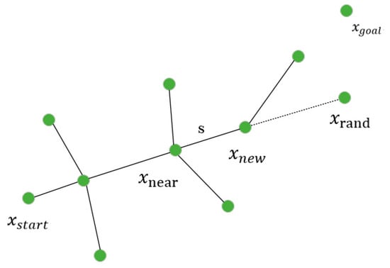
Figure 1.
RRT node expansion process.
The RRT* algorithm, introduced in 2010 as an enhanced version of the original RRT algorithm, maintains the probabilistic completeness of RRT while adding asymptotic optimality. By randomly sampling the reachable space of the UAV and ensuring collision detection and non-integrity constraint detection for each new node before connecting to the tree, this improved version can converge to an optimal solution with sufficient iterations.
Although capable of producing higher-quality paths, the RRT* algorithm requires additional computational effort due to the two following key processes when generating new nodes: re-selecting the parent node and path rerouting. These steps are designed to minimize the path cost for newly generated nodes and reduce redundant paths within the random tree, but they also result in an increased search time. Subsequently, we present the pseudo-code of the RRT* algorithm [16], as depicted in Algorithm 1.
| Algorithm 1 RRT* |
| 1: V ← {}; E ← ; 2: for each iter ∈ [1,Maxiter] do 3: ← Sample(iter); 4: ← Nearest (V, ); 5: ← Steer (, ); 6: if Collisionfree (, , ) then 7: ← Near (V, ); 8: ← CℎooseParent (, , ); 9: V ← V ∪ { }; 10: E ← E ∪ {(, )}; 11: G ← Rewire(G, , ); 12: end if; 13: end for 14: Return G = (V, E); |
represents the initial point, while denotes the target point. The variable signifies a randomly sampled point within the space, and refers to the node closest to in the random tree. Additionally, is extended along a straight line between and , with step representing the step size used for this extension.
The primary distinction between the RRT* algorithm and the RRT algorithm lies in the rediscovery of the parent node for a new node in Algorithm 2, as well as the updating of child nodes in Algorithm 3, which leads to an enhanced quality of the selected tree nodes. The path cost of the RRT* algorithm is considerably lower than that of the RRT algorithm.
| Algorithm 2 Choose Parent (, , ) |
| 1: ← ; 2: ← Cost () + dist(, ); 3: for each ∈ do 4: Cdist ← C() + dist(, ); 5: if Collisionfree (, , ) then 6: if Cmindist < Cdist then 7: Cmindist = Cdist; 8: ← 9: end if; 10: end if; 11: end for 12: Return |
| Algorithm 3 Rewire (G, ) |
| 1: for each ∈ do 2: if C () + dist (, ) < C () then 3: qparent ← Parent(); 4: E ← Reconnect(, ); 5: end if; 6: end for 7: Return G = (V, E); |
In the above pseudo-code, the relevant function is explained as follows:
- Sample: A random sampling function that obtains random sampling points in the space.
- Nearest: Returns a point in the search tree with the shortest distance from a random point .
- Steer: Returns a new node that is along the direction of the nearest point , extended with a fixed step size.
- Cost: Assuming a random tree generates a node, it returns the path length from the starting point to that node.
- dist: Calculates the Euclidean distance between two points.
- Near: Returns the set of parent nodes for the new node.
- Collisionfree: Detects the presence of an obstacle between two points.
- Reconnect: The function to connect a new node to a new parent node.
3.2. Informed-RRT*
The Informed RRT algorithm represents a further improvement and extension of the RRT algorithm. The two algorithms are not different until the initial solution is found. However, once the Informed RRT* algorithm obtains the initial solution, it begins to use the optimization costs of the starting point , the ending point , and the best path obtained in the current iteration to guide its subsequent exploration. For this purpose, please refer to Figure 2. the algorithm creates an ellipsoidal sampling space and performs further sampling and exploration only within this particular ellipsoidal histogram subset region to optimize the paths more efficiently and reduce the computational consumption of extraneous regions, constructing the following ellipsoidal histogram subset region of:
where is the distance between the two foci, and are the hyperelliptic region’s foci, and is the region’s long axis. This region enhances the algorithm’s efficiency by decreasing the sampling area and raising the likelihood that a valid node will be sampled. Additionally, as the path is increasingly optimized, is shortened and the hyperelliptic region shrinks. This accelerates the algorithm’s convergence speed and speeds up the convergence to the optimal solution. The process is shown in Algorithm 4. The main improvement of the Informed-RRT * algorithm is to reduce the sampling range of by using the SampleInformed function, as shown in Algorithm 5:
| Algorithm 4 Informed-RRT* |
| 1: V ← {}; 2: E ← ; 3: ← ∅; 4: for each iter ∈ [1,Maxiter] do 5: ← minqsoln∈ {Cost()}; 6: ← InformedSample (, , ); 7: ← Nearest (V, ); 8: ← Steer (, ); 9: if Collisionfree (, , ) then 10: ← Near(V, , Rnear); 11: ← ChooseParent(, , ); 12: V ← V ∪ {} 13: E ← E ∪ {(, )} 14: G ← Rewire(G, , ); 15: end if; 16: if InGoalRegion () then 17: ← ∪ {} 18: end if; 19: end for 20: Return G = (V, E) |
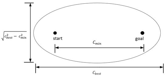
Figure 2.
Hyperellipsoidal sampling region of Informed-RRT*.
| Algorithm 5 Sample Informed(, , ) |
| 1: if ← ∞ then 2: ←; 3: ← (+)∕2; 4: C ← RotationToWorldFrame(, ); 5: ← V∕2; 6: { }i=2,⋅⋅⋅,n ← ()∕2; 7: L ← diag{, , ⋅ ⋅ ⋅,}; 8: ← SampleUnitNBall; 9: ← (CL+ ) ∩ X; 10: else 11: ← U(X); 12: return ; |
The following explains the new function in Informed-RRT*:
- RotationToWorldFrame: Utilized for converting the input data into the global coordinate system.
- InGoalRegion: Determines whether the target region contains the input node. It returns True if it is within the target point’s region. If not, False is returned.
3.3. APF
In complex environments, path planning remains a formidable task, even with drones having access to global map information. The drone must navigate towards the target position while avoiding obstacles. The essence of the APF method [17] lies in the generation of attractive and repulsive potential fields by the target point and obstacles, respectively. By superimposing these two potential fields, the potential energy at any point can be determined, enabling path planning based on minimizing this energy. This approach does not rely on global obstacle information and allows for local obstacle detection and avoidance. The working principle is illustrated in Figure 3, where denotes the repulsive force exerted by obstacles on the UAV and represents the attraction of the target point to the UAV.
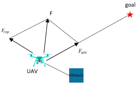
Figure 3.
Schematic of the forces on the UAV.
In order to calculate the gravitational and repulsive forces of the UAV, the field functions for gravity and repulsion are initially defined. By taking the negative gradient of these potential field functions, we can obtain the gravitational and repulsive force functions. The classical expressions for these force fields are as follows.
The common gravitational field function is as follows:
where P represents the current coordinates of the UAV, represents the coordinates of the goal point, and is the attraction gain coefficient.
The common repulsive field function is as follows:
where P is the current coordinates of the UAV and is the coordinates of the obstacle for which the potential function is being computed; Q is the obstacle action range, outside of which obstacles will not affect the UAV flight; and is the repulsive force gain coefficient.
Under the above definition of the potential function, the gravitational potential produced by the goal point decreases as an object approaches it, while the repulsive potential produced by the obstacle increases with an object’s proximity to it.
The object moves to the position with a smaller potential, so it can approach the target point and move away from the obstacle.
4. Algorithm Convergence and Improvement
Although the Informed-RRT* algorithm has strong search capabilities, it often fails to generate safe paths when faced with unknown static and dynamic obstacles. On the other hand, the DWA algorithm has the advantages of a good real-time performance and compatibility with drone motion characteristics, but it often encounters issues such as overly long paths, getting stuck in local optima, and failing to reach the target point.
To address these issues, this paper proposes a path planning method that combines the improved Informed-RRT algorithm with the DWA. Firstly, the improved Informed-RRT algorithm is used to plan the globally optimal path, and key points along this path are extracted as intermediate nodes for the DWA algorithm. Then, the dynamic window approach is employed to perform local path planning between each pair of adjacent nodes, dynamically avoiding obstacles and adjusting and optimizing the path. Specifically, the algorithm iteratively optimizes the global path and combines the DWA algorithm to perform real-time adjustments in local areas, adapting to dynamic changes in the environment and ensuring the safety and effectiveness of the path. The advantage of this fusion algorithm lies in fully utilizing the global search capabilities of Informed-RRT* and the real-time performance of the DWA, dynamically adjusting both the global and local paths to effectively deal with obstacles and dynamic changes in complex environments, thereby improving the success rate and efficiency of path planning. The specific algorithm improvements and fusion are as follows:
- High-quality sampling strategies: An adaptive factor is added to adjust the sampling strategy based on the Euclidean distance between the target point and the algorithm, which enhances the randomness at the beginning of the sampling process and accelerates the convergence near the end of the path, avoiding falling into the local optimum too early and improving the efficiency of finding the effective path, which accelerates the sampling speed.
- Efficient Search Strategies: In order to ensure that the target point and random sampling point of each tree have an attractive force toward the nearest node and that the obstacle has a repulsive force toward the nearest node, respectively, the APF notion is added during the process of generating new nodes. Trajectory search and obstacle avoidance become more efficient when the total direction of the three forces is used as the new node’s growth direction.
- Path Optimization: The updated algorithm’s path is still convoluted, despite a relative gain in sampling quality and running performance. Reducing the path’s distortion is, therefore, essential to prevent issues like flying at an excessively high speed and angle. This study uses the cubic spline interpolation approach to further optimize the generated path, making it smoother and taking into account the UAV’s turning radius restriction, making it more appropriate for UAV flight in real-world scenarios.
- Addition of the Dynamic Window Approach: The Informed-RRT* algorithm first generates a collision-free path from the starting point to the target point in the global space. This path is provided as an initial reference path to the DWA algorithm. During actual operation, the DWA algorithm dynamically adjusts control inputs based on the current position, speed, and reference path of the UAV, ensuring that the UAV can avoid dynamic obstacles in real time while maintaining its proximity to the reference path as much as possible.
The flowchart of the whole algorithm is shown in Figure 4:
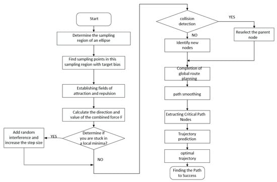
Figure 4.
Algorithm flow chart.
4.1. Improved Informed-RRT*
The random sampling point selection can be improved. In the elliptic search space, is randomly obtained in the original Informed-RRT* algorithm. Here, an adaptive function is introduced, which dynamically adjusts the probability weights of the sampling directions according to the Euclidean distance between the starting point and the target point as follows:
where S computes the normalized value of the distance from the starting point to the endpoint. In this paper, it is assumed that the maximum considered distance is n = 1000 units in length. This value decreases as the distance between the starting point and the endpoint increases. By subtracting 1 − norm ()/n, it can be transformed into a heuristic adjustment factor, such that the closer the distance, the larger this value becomes. When the adaptive value is small, indicating a shorter distance between the starting point and the endpoint (e.g., 100 units in length), such as when the adaptive value approaches 0.9, the algorithm is more likely to choose a strategy leaning towards the direction of the target during sampling by multiplying with m (the existing sampling probability control parameter).
where rand () represents a random number ranging from 0 to 1 and m is the controlling parameter for the sampling probability. The growth direction of new nodes in the random tree is determined by m. If rand () < m × S, then the tree will grow randomly within the sampling space; otherwise, it will extend towards the target point of each growth tree.
When the distance between the starting and end points is short, the factor value approaches 1, increasing the probability of direct sampling towards the target direction, thereby accelerating the final convergence of the path. Conversely, if the distance between the starting and end points is long, the adaptive value approaches 0, reducing the proportion of direct target sampling and adopting more random sampling. This enhances the algorithm’s random exploration characteristics, helping to avoid prematurely falling into local optima and ensuring the comprehensiveness of path exploration.
4.2. Improved APF–Informed-RRT*
Building upon the enhanced Informed-RRT* algorithm, a refined APF algorithm [18] is incorporated into the direction generation process within the sampling interval. This fusion assists in guiding the expansion of the random tree towards the target point while mitigating excessive randomness. In the first step of the specified step, grows along the combined direction of the tree, where the target point, the random sampling point, and the obstacle exert attractive and repulsive forces, respectively, on . The combined direction of the tree is the direction of generation. Figure 5 displays the schematic diagram of the force.
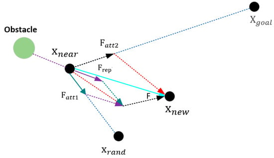
Figure 5.
Force analysis diagram of APF–RRT*.
- (1)
- Introduction of gravitational components
Reducing the unpredictability of tree growth, the random tree’s growth direction can be regulated to grow towards the target location by adding attractive force components to its random nodes. In this study, an attractive force function (x) is introduced into each new node nn to change the resultant force direction of growth.
In Equation (10), is the function determining new nodes for the random tree during the search process, is the function for the random growth of new nodes, and is the function for adding target attraction.
The target attraction function is as follows:
where is the target position vector and represents the absolute value of the geometric distance between node and .
The random growth function for new nodes is as follows:
- (2)
- Introducing the repulsive component:
The concept of obstacle repulsion from Artificial Potential Fields can be integrated into the improved Informed-RRT* algorithm to guide the growth of the local random tree away from obstacles. Specifically, during the expansion process of the local random tree search, a repulsive force function () is introduced for each newly generated node n. The expression of this function is as follows:
In Equation (13), F() is the function that determines new nodes in the random tree during the search process, is the random growth function for new nodes, and () is the repulsive force function from obstacles to the new nodes.
The obstacle repulsion function is as follows:
However, the local minima problem arises when the UAV is about to approach the target because of nearby obstacles and a repulsive force of the UAV that is stronger than the gravitational pull. This makes it difficult for the UAV to fly to the target. Therefore, in this paper, a stochastic perturbation function is introduced, while the step size is increased to provide the UAV with more chances to escape when it falls into a local minimum.
where a and b are the scale factor.
So, finally, the combined force on the drone is as follows:
4.3. Path Optimization
Although these fused and improved algorithms introduce relative improvements in terms of sampling tuning and operating speed, the paths are still tortuous. This is very unfavorable for UAVs performing autonomous navigation tasks. Therefore, in order to avoid problems such as an insufficient smoothness and excessive angle when a UAV flies to the target point, it is necessary to continue to optimize the path in order to reduce its distortion.
Cubic spline interpolation [19] interpolates the collected data. The interpolation is similar in shape, and every known point passes through, generally using piecewise interpolation. In order to prevent the turning radius of the UAV from being too large when moving at a high speed, the curvature of each point is considered in the interpolation, and the curvature is restricted and constrained. The curvature describes the degree of the curvature of the path at a certain point, and the specific calculation formula is as follows:
and represent the tangent vector components of the curve. and represent the acceleration components of the curve.
where v is the speed of the drone, is the maximum thrust of the drone, is the maximum tilt angle of the drone, and m is the mass of the drone.
represents the maximum curvature, and when the curvature k of a point exceeds the maximum curvature , the interpolation point needs to be adjusted to reduce the curvature. G is the scaling factor used to scale the displacements and , thereby reducing the curvature. and denote the adjusted interpolation coordinates. The curvature of the interpolation points should be adjusted to meet the requirements so that the curvature of the path does not exceed the set maximum value at all points.
4.4. Dynamic Window Algorithms
Based on predictive control theory, the Dynamic Window Approach (DWA) [20] is a suboptimal method that may safely and effectively avoid obstacles in unfamiliar situations while maintaining a modest computation, fast response times, and a good operability. Planning local paths is the primary use for the Dynamic Window method [21]. The action trajectory moments of the subsequent set of velocity values are simulated using velocity values that are sampled from several sets in the velocity space. Simultaneously, the best trajectory is obtained for path planning and the anticipated trajectory is reasonably evaluated. The three following primary components make up the entire algorithmic procedure [22]: the trajectory assessment function, the velocity sample acquisition, and the motion model establishment.
4.4.1. Knematics Model
The Dynamic Window’s primary purpose is to confine the velocity sampling space to a workable dynamic range depending on the UAV’s acceleration and deceleration characteristics.
The following is the basic idea behind motion trajectory simulation [23]. Projecting the UAV’s motion distance on the x and y axes of the ground coordinate system and assuming that the motion trajectory is approximated as a straight line due to the short neighboring moments when calculating the motion trajectory, the trajectory at the moment of t+1 is obtained to be represented as follows:
In the equations, and represent the x and y coordinates of the UAV at time t, and represent the linear velocity and angular velocity of the UAV at time t, and is the time step representing the time elapsed for each update. and are the accelerations in the x and y directions, respectively. represents the yaw angle of the UAV at time t.
4.4.2. Velocity Sampling Device
- (1)
- Based on the constraint of the maximum value.
Firstly, the UAV’s motion is subject to its own maximum and minimum speed constraints, which are specifically represented as follows:
- (2)
- In light of the acceleration and deceleration constraints.
The UAV’s acceleration and deceleration capabilities also limit it simultaneously, and the maximum movement speed that it can achieve within a Dynamic Window period is indicated as follows:
In the equation, and represent the maximum and minimum velocity accelerations, respectively, while and represent the maximum and minimum angular velocity accelerations.
- (3)
- Based on the constraint of safety distance.
To ensure the drone stops safely when encountering obstacles, a speed limit range is established.
is the distance from the nearest obstacle on the trajectory predicted by the velocity.
4.4.3. Trajectory Evaluation Subfunction
After obtaining many sets of velocity numbers, each trajectory must be carefully reviewed in order to determine which is the best expected trajectory. The specific technique is to thoroughly assess each trajectory’s performance using the designated evaluation function in order to choose the trajectory that has the highest priority. The following is the improved evaluation function:
- : The angle difference between the UAV’s orientation at the end of its trajectory and the target is assessed using the heading assessment function. A smaller angle difference results in a higher evaluation score.
- : This is a function for evaluating distance that is primarily used to calculate how far a UAV is from the closest obstacle along its current route. The higher the evaluation score, the further away from the obstacle the UAV is.
- : This represents the velocity evaluation function, which is mostly used to assess the current trajectory’s velocity in an effort to maintain the UAV’s maximum speed.
- : This is a function for evaluating the smoothness of a path, while acceleration serves as the foundation for judgment. The calculation method is = .
5. Simulation Result Analysis
To validate the efficacy of the proposed enhanced fusion algorithm, three distinct environments are initially formulated. A comparative analysis is conducted between the proposed improved Informed-RRT*, RRT*, and Informed RRT* algorithms using three evaluation metrics. To mitigate the stochastic nature of sample-based algorithms, each algorithm is independently executed 30 times with a maximum of 800 iterations. Uniform simulation parameters are set for all algorithms to ensure an equitable comparison. Subsequently, dynamic obstacles and those not present in the global path are introduced into the original map to assess real-time obstacle avoidance post DWA integration. The simulation platform and its configuration include Matlab R2021a; a 64-bit Windows 10 operating system; Processor 12th Gen Intel(R) Core (TM) i5-12400F 2.50 GHz; and a running memory of 32 GB.
The three following test environments were designed: general, narrow, and cluttered. These environments are based on common working conditions for drones in real life and are shown in Figure 6. In these environments, red circles represent starting points, red circles represent target points, light green rectangles and circles represent static obstacles, and green circles represent dynamic obstacles. The dimensions of these three environments are all 100 by 100.
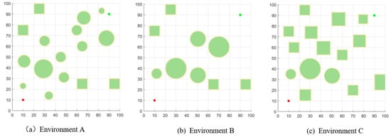
Figure 6.
Simulation environment.
5.1. In Environment A
The simulation results for Environment A are shown in Figure 7, where the blue line indicates the drone flight trajectory planned by the algorithm. In Figure 7a, due to the large sampling space used by the RRT* algorithm, the trajectory contains many turning points, resulting in a longer path and an increased computation time. The simulation results of the Informed-RRT* algorithm are shown in Figure 7b. Compared to the original RRT* algorithm, by limiting the sampling interval, it can generate better paths in the same number of iterations, and the growth of the random tree is faster, thus reducing the required time. Although the Informed-RRT* algorithm has an improved search efficiency, it lacks obstacle repulsion, leading to many redundant points around obstacles. Compared to the Informed-RRT* algorithm, Figure 7c shows the improvements made to the original Informed-RRT*. The generation of new nodes includes an improved APF, and the generated paths are smoothed. These enhancements further improve the search efficiency of the algorithm; the improved algorithm not only makes the planned path smoother and shorter, but also better meets the flight requirements of the drone.

Figure 7.
Simulation in Environment A.
In order to confirm the stability of the algorithms, this article performs 30 tests in the same environment for each algorithm, noting the number of nodes, trajectory length, and execution time for each. Table 1 displays the simulation data for Environment A.

Table 1.
Simulation date in environment A.
By examining the data shown in Table 1, the trajectory planning algorithm suggested in this work shortens the trajectory by 3.86% when compared to the Informed-RRT* algorithm. Both the number of nodes and the average operating time drop by 75.95% and 81.65%, respectively. The outcomes show that this method demonstrates stability, speeds up the algorithm’s convergence, and drastically cuts down on the amount of redundant points. Its success rate is also much higher.
5.2. In Environment B
The trajectories planned by the three algorithms in Environment B are shown in Figure 8. Figure 8c displays the flight trajectory of the novel algorithm presented in this paper. The flight path is smoother, straighter, and produces fewer redundant points than other algorithms, better fulfilling the requirements for UAV flight.
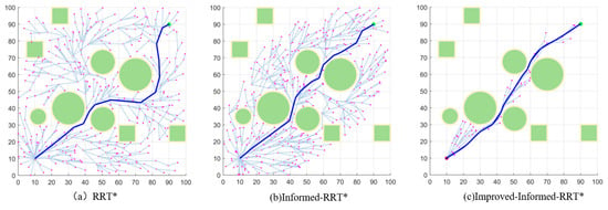
Figure 8.
Simulation in Environment B.
Based on the data analysis in Table 2, the average trajectory length generated by the algorithm in this paper is 6.71% shorter than the average trajectory length of the Informed-RRT* algorithm; the average running time is shortened by 75.65%; and the average number of nodes is lowered by 66.99%. The success rate is also much higher. These results suggest that the algorithm is more stable and has a higher search efficiency in more complex environments.

Table 2.
Simulation date in Environment B.
5.3. In Environment C
The benefits of the algorithm presented in this study are even more evident for Environment C, which has more intricate impediments. In this intricate setting, the algorithm finds smoother and shorter pathways. As seen in Figure 9c, it also greatly shortens the search time and removes a great deal of unnecessary points. By comparing the new algorithm to the Informed-RRT* algorithm and analyzing the data in Table 3, the average path length is reduced by 7.36%. The average running time is 71.71% less than the algorithm, while the average number of nodes is 64.53% shorter. As a result, this algorithm’s stability can be demonstrated by its capacity to significantly lower the number of redundant points.

Figure 9.
Simulation in Environment C.

Table 3.
Simulation date in Environment C.
In Figure 10, we compare the path length, execution time, number of nodes traversed, and obstacle avoidance rate of the trajectories generated by each algorithm across three different environments. The results clearly indicate that the algorithm proposed in this paper outperforms the others.

Figure 10.
Comparison chart of simulation data in three environments.
5.4. Path Optimization
The path optimization results in the three environments shown in Figure 11. Although the route generated by the original path is feasible, it contains many trajectory points and the path length is long, which is difficult to adapt to the flight requirements of the actual UAV environment. To address this problem, the proposed method adopts the cubic spline interpolation method and considers the steering radius of the UAV to optimize the path generated by the improved algorithm. In the figure, the red path represents the original path and the blue path represents the optimized path. It can be seen that, after optimization, the redundant points in the path are reduced and the trajectory is smoother, which better meets the flight requirements of UAVs in real scenarios.
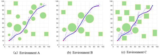
Figure 11.
Path optimization in three simulation environments.
5.5. In Dynamic Environment
As shown in Figure 12, Figure 13 and Figure 14, dynamic obstacles and obstacles that are not on the initial path are added to these three environments, and facing these two kinds of unknown obstacles can be used to form a suitable obstacle avoidance speed of the UAV by the speed relative to the dynamic obstacles, which ensures that the obstacles are avoided while trying to stay near the original path. A comparison is also made between the DWA and the improved algorithm, with the improved fused algorithm performing better in complex dynamic environments.
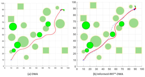
Figure 12.
Dynamic obstacle avoidance in Environment A.
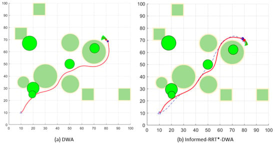
Figure 13.
Dynamic obstacle avoidance in Environment B.
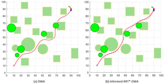
Figure 14.
Dynamic obstacle avoidance in Environment C.
6. Conclusions
This paper proposes a UAV path planning method that combines an improved Informed-RRT* algorithm with an enhanced DWA algorithm to address the path planning problems faced by UAVs in environments with dynamic or unknown static obstacles. Compared to the traditional Informed-RRT* algorithm, the improved Informed-RRT* algorithm reduces the path length and planning time and eliminates a large number of redundant nodes, demonstrating its effectiveness and superiority. Firstly, the Informed-RRT* algorithm generates a collision-free path from the starting point to the goal point in the global space, which serves as the initial reference path for the DWA algorithm. During actual operation, the DWA algorithm dynamically adjusts control inputs based on the UAV’s current position, speed, and reference path, ensuring that the UAV can avoid dynamic obstacles and unknown static obstacles in real time while staying as close to the reference path as possible. This combined method not only improves path planning efficiency, but also enhances the UAV’s adaptability in complex and dynamic environments, making it more consistent with real UAV flight scenarios. The next step in the work is to adapt the algorithm by adding the dynamics constraints of the UAV considering a three-dimensional case, which would make it more consistent with real flight scenarios.
Author Contributions
Conceptualization, T.W. and Z.Z.; methodology, T.W.; software, Z.Z.; validation, M.G., Z.Z. and T.W.; formal analysis, F.J.; investigation, M.G.; resources, F.J.; data curation, Z.Z.; writing—original draft preparation, Z.Z.; writing—review and editing, T.W. and M.G.; supervision, T.W.; project administration, F.J.; funding acquisition, Z.Z. All authors have read and agreed to the published version of the manuscript.
Funding
Information and Communication Business Cost Project of JSCMC, Grant/Award Number: SXJD-XXTXF-202303. Scientific Research Plan of JSLLKYJH, Grant/Award Number: 23-JSLLKY011.
Data Availability Statement
No new data were created. Data are contained within the article.
Conflicts of Interest
The authors declare no conflicts of interest.
References
- Fransen, K.; van Eekelen, J. Efficient path planning for automated guided vehicles using a* (astar) algorithm incorporating turning costs in search heuristic. Int. J. Prod. Res. 2023, 61, 707–725. [Google Scholar] [CrossRef]
- Husain, Z.; Al Zaabi, A.; Hildmann, H.; Saffre, F.; Ruta, D.; Isakovic, A.F. Search and rescue in a maze-like environment with ant and dijkstra algorithms. Drones 2022, 6, 273. [Google Scholar] [CrossRef]
- LaValle, S.M. Rapidly-Exploring Random Trees: A New Tool for Path Planning; Annual research report; Iowa State University: Ames, IA, USA, 1998. [Google Scholar]
- Karaman, S.; Frazzoli, E. Sampling-based algorithms for optimal motion planning. Int. J. Robot. Res. 2011, 30, 846–894. [Google Scholar] [CrossRef]
- Gammell, J.D.; Srinivasa, S.S.; Barfoot, T.D. Informed RRT*: Optimal sampling-based path planning focused via direct sampling of an admissible ellipsoidal heuristic. In Proceedings of the 2014 IEEE/RSJ International Conference on Intelligent Robots and Systems, Chicago, IL, USA, 14–18 September 2014; pp. 2997–3004. [Google Scholar]
- Huang, J.; Sun, W. A method of feasible trajectory planning for UAV formation based on bi-directional fast search tree. Optik 2020, 221, 165213. [Google Scholar] [CrossRef]
- Fan, J.; Chen, X.; Liang, X. UAV trajectory planning based on bi-directional APF-RRT* algorithm with goal-biased. Expert Syst. Appl. 2023, 213, 119137. [Google Scholar] [CrossRef]
- Javed, S.; Hassan, A.; Ahmad, R.; Ahmed, W.; Alam, M.M.; Rodrigues, J.J.P.C. UAV trajectory planning for disaster scenarios. Veh. Commun. 2023, 39, 100568. [Google Scholar] [CrossRef]
- Zhu, B.; Bedeer, E.; Nguyen, H.H.; Barton, R.; Henry, J. UAV Trajectory Planning in Wireless Sensor Networks for Energy Consumption Minimization by Deep Reinforcement Learning. IEEE Trans. Veh. Technol. 2021, 70, 9540–9554. [Google Scholar] [CrossRef]
- Papaioannou, S.; Kolios, P.; Theocharides, T.; Panayiotou, C.G.; Polycarpou, M.M. Unscented Optimal Control for 3D Coverage Planning with an Autonomous UAV Agent. In Proceedings of the 2023 International Conference on Unmanned Aircraft Systems (ICUAS), Warsaw, Poland, 6–9 June 2023; pp. 703–712. [Google Scholar]
- Keyu, L.; Yonggen, L.; Yanchi, Z. Dynamic obstacle avoidance path planning of UAV Based on improved APF. In Proceedings of the 2020 5th International Conference on Communication, Image and Signal Processing (CCISP), Chengdu, China, 13–15 November 2020; pp. 159–163. [Google Scholar]
- Bai, X.; Jiang, H.; Cui, J.; Lu, K.; Chen, P.; Zhang, M. UAV Path Planning Based on Improved A and DWA Algorithms. Int. J. Aerosp. Eng. 2021, 2021, 4511252. [Google Scholar] [CrossRef]
- Feng, Z.; Zhou, L.; Qi, J.; Hong, S. DBVS-APF-RRT*: A global path planning algorithm with ultra-high speed generation of initial paths and high optimal path quality. Expert Syst. Appl. 2024, 249, 123571. [Google Scholar] [CrossRef]
- Dai, J.; Li, D.; Zhao, J.; Li, Y. Autonomous Navigation of Robots Based on the Improved Informed-RRT * Algorithm and DWA. J. Robot. 2022, 2022, 3477265. [Google Scholar] [CrossRef]
- Wang, G.; Jiang, C.; Tao, G.; Ye, C. Dynamic path planning based on the fusion of improved RRT and DWA algorithms. In Proceedings of the 2023 4th International Conference on Mechatronics Technology and Intelligent Manufacturing (ICMTIM), Nanjing, China, 26–28 May 2023; pp. 534–538. [Google Scholar]
- Ding, J.; Zhou, Y.; Huang, X.; Song, K.; Lu, S.; Wang, L. An improved RRT* algorithm for robot path planning based on path expansion heuristic sampling. J. Comput. Sci. 2023, 67, 101937, ISSN 1877-7503. [Google Scholar] [CrossRef]
- Diao, Q.; Zhang, J.; Liu, M.; Yang, J. A Disaster Relief UAV Path Planning Based on APF-IRRT* Fusion Algorithm. Drones 2023, 7, 323. [Google Scholar] [CrossRef]
- Huang, S. Path Planning Based on Mixed Algorithm of RRT and Artificial Potential Field Method. In Proceedings of the 2021 4th International Conference on Intelligent Robotics and Control Engineering (IRCE), Lanzhou, China, 18–20 September 2021; pp. 149–155. [Google Scholar]
- McKinley, S.; Levine, M. Cubic spline interpolation. Coll. Redw. 1998, 45, 1049–1060. [Google Scholar]
- Wang, W.; Ru, L.; Lu, B.; Hu, S. Path Planning of UAV Crossing Dense Obstacle Area Based on Improved Dynamic Window Approach. In Proceedings of the 2023 5th International Conference on Electronic Engineering and Informatics (EEI), Wuhan, China, 30 June–2 July 2023; pp. 468–473. [Google Scholar]
- Zhang, Y.; Xiao, Z.C.; Yuan, X.X. Obstacle avoidance of two-wheeled mobile robot based on DWA algorithm. In Proceedings of the 2019 Chinese Automation Congress (CAC), Hangzhou, China, 22–24 November 2019; pp. 5701–5706. [Google Scholar]
- Molinos, E.J.; Llamazares, A.; Ocana, M. Dynamic window based approaches for avoiding obstacles in moving. Robot. Auton. Syst. 2019, 118, 112–130. [Google Scholar] [CrossRef]
- Li, L.T.; Sheng, W. Collision Avoidance Dynamic Window Approach in Multi-agent System. In Proceedings of the 2020 Chinese Automation Congress (CAC), Shanghai, China, 6–8 November 2020; pp. 2307–2311. [Google Scholar]
Disclaimer/Publisher’s Note: The statements, opinions and data contained in all publications are solely those of the individual author(s) and contributor(s) and not of MDPI and/or the editor(s). MDPI and/or the editor(s) disclaim responsibility for any injury to people or property resulting from any ideas, methods, instructions or products referred to in the content. |
© 2024 by the authors. Licensee MDPI, Basel, Switzerland. This article is an open access article distributed under the terms and conditions of the Creative Commons Attribution (CC BY) license (https://creativecommons.org/licenses/by/4.0/).