Article

OF-FSE: An Efficient Adaptive Equalization for QAM-Based UAV Modulation Systems

1
School of Cyber Science and Engineering, Zhengzhou University, Zhengzhou 450001, China
2
School of Electrical and Information Engineering, Zhengzhou University, Zhengzhou 450001, China
3
School of Computing and Communications, Lancaster University, Lancaster LA1 4WA, UK
*
Author to whom correspondence should be addressed.
Drones 2023, 7(8), 525; https://doi.org/10.3390/drones7080525
Submission received: 13 June 2023 / Revised: 6 August 2023 / Accepted: 7 August 2023 / Published: 10 August 2023
(This article belongs to the Section Drone Communications)

Abstract

:
Quadrature amplitude modulation (QAM) is one of the essential components of unmanned 1 aerial vehicle (UAV) communications. However, the output signal accuracy of QAM deteriorates dramatically and even collapses in the case of UAVs in a harsh channel environment. This is due to the fractionally spaced equalization based on the multi-modulus blind equalization algorithm being implemented prior to carrier synchronization in QAM-based UAV modulation systems. The carrier frequency offset from the harsh channel signal thus contributes to the significantly degraded performance of MMA by suffering the fractionally spaced equalization. Therefore, in this paper, a novel offset feedback fractionally spaced equalization architecture for UAVs to eliminate the carrier frequency offset is first proposed. In this architecture, the carrier frequency offset allows estimated and incorporation into the input signal of fractionally spaced equalization to compensate for the offset. Moreover, a new multi-modulus decision-directed algorithm is presented for the novel architecture to improve the received signal accuracy of UAVs further. It enables adaptive optimization of the convergence process in accordance with the dynamic UAV communication environment employing the multi-modulus blind equalization algorithm and decision-directed blind equalization algorithm (MDD). Simulation results demonstrate the effectiveness of the OF-FSE framework in enabling the QAM-based UAV modulation systems operation in harsh channel scenarios. Moreover, the performance of the presented new MDD algorithm compared with baseline approaches is also confirmed.

1. Introduction

The development of wireless communication systems imposes increasingly high requirements on the transmission rate of unmanned aerial vehicles (UAVs). This means that wireless communication technology of UAVs at the physical layer needs to continuously make huge improvements based on ensuring reliability [1]. Quadrature amplitude modulation (QAM) [2] is an effective and relatively reliable technology in existing UAV communication transmission systems. This is because of its excellent frequency band utilization which is widely utilized in high-speed data transmission systems. However, QAM is by no means immune to all UAV communication scenarios. For instance, the accuracy of signals deteriorates rapidly and even falls to zero after QAM-based UAV modulation when UAV communication links are suffered common inter-symbol interference (ISI) [3]. The ISI is the amplitude value of an adjacent symbol wave at a sampling moment, resulting in interference with the current symbol sampling. The sampling value obtained at the sampling point of signal affected by ISI not only includes the amplitude value of the current symbol but also the amplitude value of adjacent symbols. It makes the symbols unreliable and reduces the signal quality of communication transmission. To recover the signal to the original form and ensure transmission accuracy, eliminating the effects of the ISI in QAM-based UAV modulation systems is thus imperative and indispensable.
The multi-modulus blind equalization algorithm (MMA) [4] based on fractionally spaced equalization (FSE) looks promising to address the challenges that QAM-based UAV modulation systems face in the ISI environment [3,5,6]. The FSE [7,8,9] enables sampling of the received signal at a greater symbol rate compared with the conventional symbol-spaced equalization. Insensitive to the sampling phase, functional timing and compensation for serious distortion of deep fading channels are the outstanding advantages of the FSE. MMA based on FSE (MMA-FSE) allows both the modulus and the phase of the equalizer output to be considered because the cost function of MMA can be decomposed into real and imaginary parts. Generally, MMA-FSE is usually used before carrier synchronization in QAM-based UAV modulation systems [10]. Nevertheless, in the ISI environment, there is carrier frequency offset (CFO) in the signal because of the presence of phase deviation because of channel delay and frequency deviation between receiver and transmitter [11]. The accuracy of the MMA-FSE however degrades precipitously or even breaks down [12]. This is due to the limited phase tracking capability of the MMA-FSE. It thus still introduces errors in the equalization and affects the accuracy of QAM-based UAV modulation systems.
Several studies have been carried out for MMA-FSE for the ISI environment [13,14,15]. Yeste Ojeda et al. [13] proposed a cyclic wiener filter to improve the FSE system based on the QAM system by using a multi-rate filter. Li et al. [14] applied multi-carrier amplitude FSE to suppress the high frequency fading in visible light communication systems. A novel class of fast MMA was proposed in [15] to improve the speed and application scenarios of MMA. However, they all ignore the implications of the CFO condition for the MMA-FSE. Yuan et al. [12] analyzed the phase tracking ability of MMA. Nevertheless, they did not provide an effective solution for reducing the impact of the CFO on MMA. Therefore, in the CFO condition, improving the capability of the FSE to correct phase deviations and thus improve the communication channel transmission accuracy of UAVs remains a pressing challenge.
Therefore, in this paper, we propose a novel offset feedback FSE (OF-FSE) architecture to decrease the influence of CFO for QAM-based UAV modulation systems. A new multi-modulus decision-directed (MDD) algorithm is then presented to improve the accuracy of our OF-FSE. The major contributions of this paper are summarized as follows:
(1)
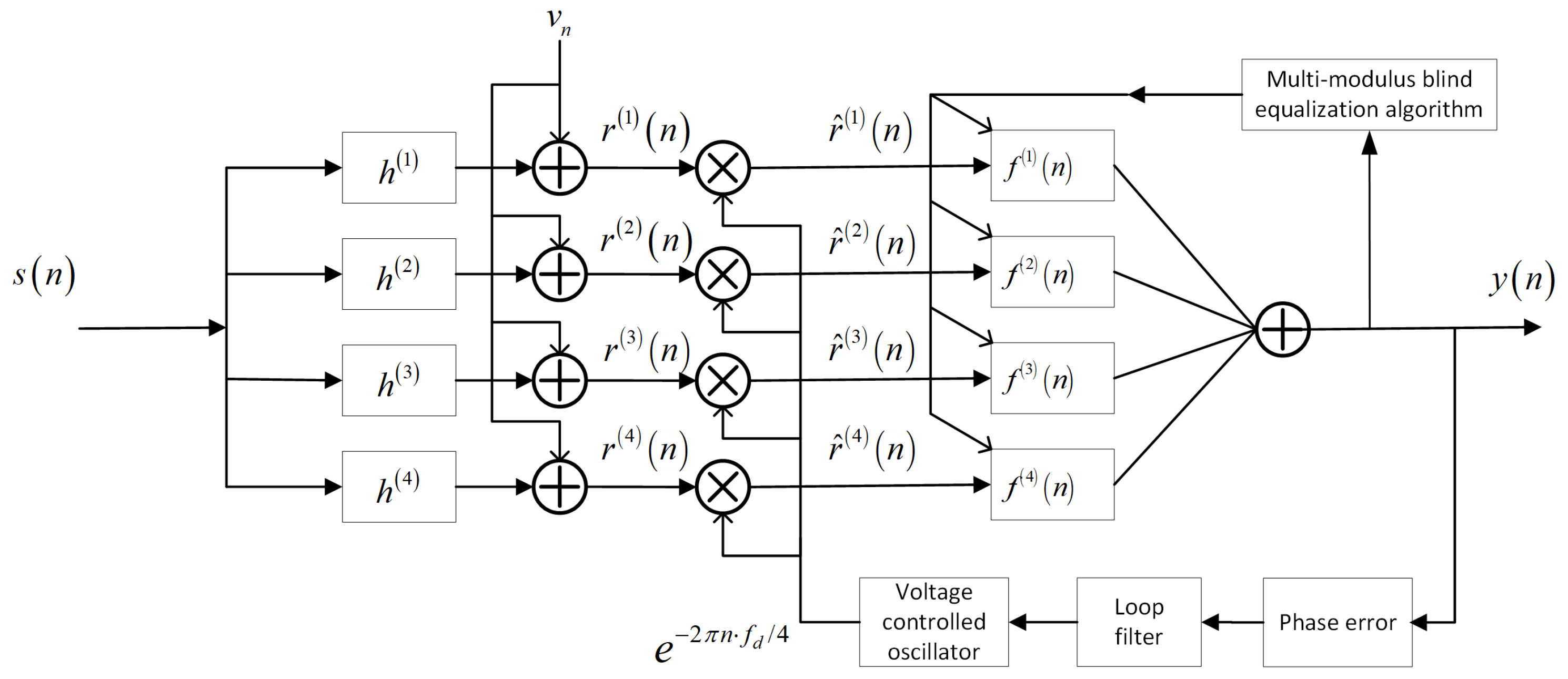
The proposed OF-FSE architecture is used to eliminate the CFO of the equalization input signal of UAVs. In particular, a feedback loop is added to FSE. It allows the OF-FSE to estimate the phase error of the output signal through a phase discriminator. The changes are then tracked to maintain the accuracy of the estimation and thus OF-FSE enables work in non-CFO conditions.
(2)
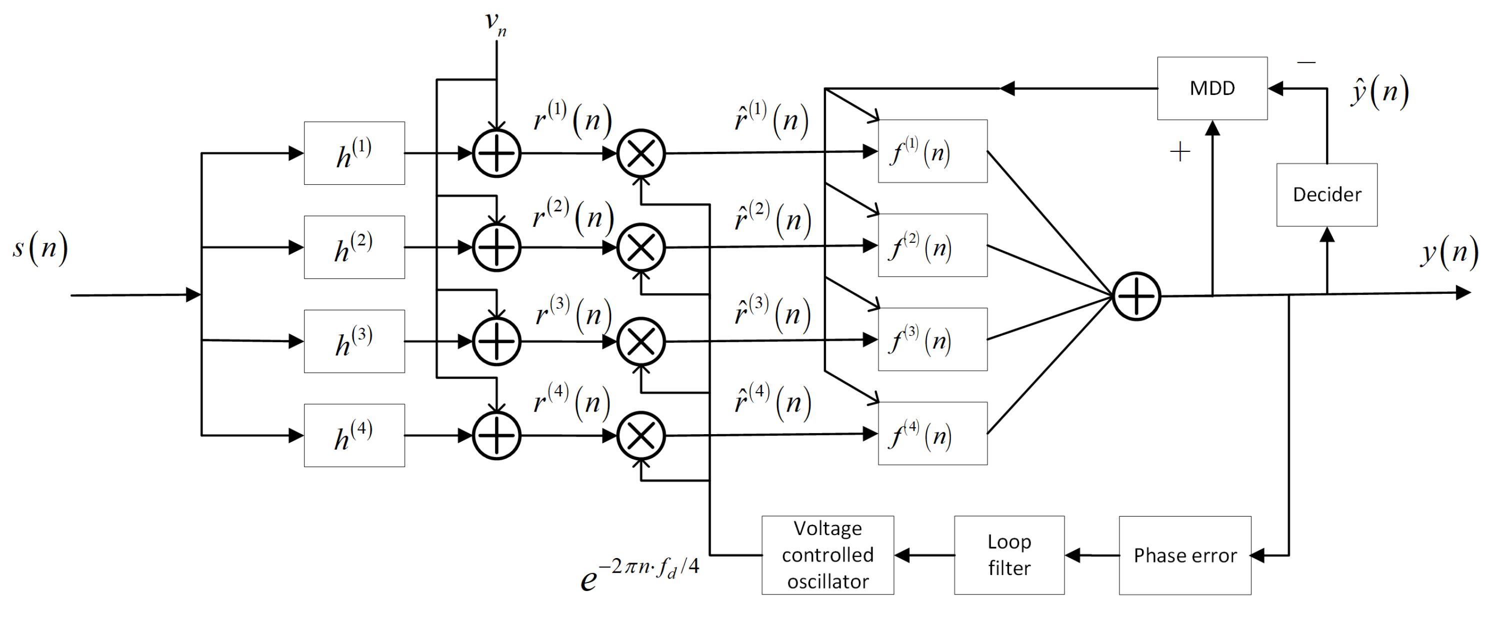
In order to further improve the output signal accuracy, a new multi-modulus decision-directed (MDD) algorithm for the novel OF-FSE is presented. It enables adaptive adjustment of the convergence status for various dynamic environments. Hence, OF-FSE can ensure stability and further reduce errors to improve accuracy.
(3)
The proposed improvements are confirmed through different aspects of the QAM-based UAV modulation system by simulations. The results demonstrate that compared with MMA-FSE, our OF-FSE can eliminate the influence of the system output signal caused by the CFO. Furthermore, the proposed new MDD algorithm enhances the accuracy compared to the baseline approaches.
The remainder of this paper is organized as follows: Section 2 introduces the general FSE architecture of QAM systems and corresponding problems in case of encountering the CFO. We present the design OF-FSE framework and demonstrate its phase tracking ability in Section 3. In Section 4, the proposed MDD algorithm is presented. Simulation results are shown in Section 5. Finally, we summarize this paper in Section 6. See Table 1 for used notation definitions.

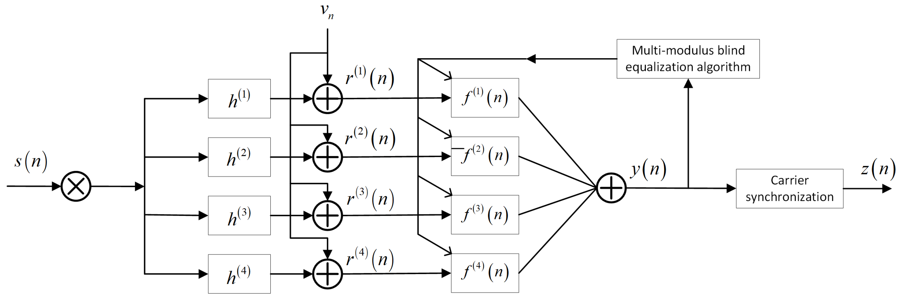
2. General FSE Architecture in QAM-Based UAV Modulation Systems

Generally, equalization and carrier synchronization are implemented in QAM-based UAV modulation systems independently. Moreover, the ISI is caused by deep path fading channels seriously and it affects the accuracy of carrier synchronization. Therefore, the implementation of MMA-FSE architecture is only be considered in this paper.
In the universal FSE carrier synchronization series architecture of QAM-based UAV modulation systems (Figure 1), FSE employs a T / 4 multi-channel model [16], where T / 4 is the sampling interval time and unit in second (s). In addition, s ( n ) , h ( n ) , v ( n ) and r ( n ) represent the transmitted signal of the baseband model, time-invariant channel impulse response, additive Gaussian white noise (AWGN) and equalization input signal, respectively. The transmitted data symbols are assumed to be stationary independently and identically distributed (i.i.d.). Furthermore, since the multi-channel model of the FSE is obtained by oversampling channel, the T / 4 oversampling channel vector can be expressed as:
h = ( h 1 ( 1 ) , h 1 ( 2 ) , , h 1 ( 4 ) , , h n ( 1 ) , h n ( 2 ) , , h n ( 4 ) , , h l h ( n ) ) ,
where l h is the channel length, h ( p ) represents different subchannels, p = 1 , 2 , 3 , 4 . In addition, P is the oversampling multiple and P = 4 in this paper.
Hence, each sub-channel vector can be represented as:
h ( p ) = ( h 1 ( p ) , h 2 ( p ) , , h l h ( p ) ) .
In addition, the signal s ( n ) transmitted through a sub-channel can be denoted by
r ( n ) = s ( n ) h ( n ) + v ( n ) = j = 1 P i = 1 l h h i ( j ) s ( n i ) + v ( n ) .
The outputs of each sub-channel can be expressed as:
r ( p ) ( n ) = i = 1 l h h i ( p ) s ( n i ) + v ( p ) ( n ) .
Further, the MMA is a blind equalization algorithm that compensates for signal amplitude and phase separately, it is characterized by the division of the transmitted signal into real and imaginary parts for updating and iterating filters. It can be achieved by iterating the errors of the real and imaginary data based on the cost function while adjusting the filter weight coefficients. The cost function of MMA [17] is
J M M A ( n ) = 1 4 E s 4 ( n ) i r 4 ( i ) cos 4 θ ( i ) + 3 4 E | s ( n ) | 4 i r 4 ( i ) + 2 E 2 | s ( n ) | 2 i l i r 2 ( i ) r 2 ( l ) 2 E 2 | s ( n ) | 2 E s R 4 ( n ) E s R 2 ( n ) i r 2 ( i ) + 2 E s R 4 ( n ) E s R 2 ( n ) 2 = E y R 4 ( n ) + E y I 4 ( n ) 2 R R · E y R 2 ( n ) 2 R I · E y I 2 ( n ) + R R 2 + R I 2
J R ( n ) and J I ( n ) is used to express the cost functions in the real and imaginary directions of the FSE output signal, they can be further specifically denoted by
{ J R ( n ) = 1 4 R R y R ( n ) 2 2 , J I ( n ) = 1 4 R I y I ( n ) 2 2 ,
where y R ( n ) and y I ( n ) are the real and imaginary parts of the FSE output signal, respectively. In addition, R R and R I are used to be invariant of cost functions, their values are related to the carrier amplitude of the signal. After the derivation of y R ( n ) and y I ( n ) , the real and imaginary parts of the FSE output signal error function can be expressed as e R ( n ) and e I ( n ) respectively by
{ e R ( n ) = y R ( n ) R R y R ( n ) 2 2 , e I ( n ) = y I ( n ) R I y I ( n ) 2 2 ,
where the expressions for the constant modulus terms R R and R I are
{ R R = E s R ( n ) 4 / E s R ( n ) 2 , R I = E s I ( n ) 4 / E s I ( n ) 2 ,
where s R ( n ) and s I ( n ) are the real and imaginary parts of the transmitted signal respectively, and E [ · ] is the mathematical expectation. The filtering coefficient update formula for the T / 4 -FSE with an iteration step of μ that can be written as:
f ( p ) ( n + 1 ) = f ( p ) ( n ) μ · ( e R ( n ) + e I ( n ) ) * · r ( p ) ( n ) , ( p = 1 , 2 , 3 , 4 ) .
The output signal y ( n ) can be expressed as Equation (10), and the ISI in y ( n ) has been eliminated by FSE,
y ( n ) = r n j = 1 P i = 1 l f f i ( j ) r ( n i ) + v n ,
where l f is the filter length, f n = ( f ( 1 ) , f ( 2 ) , , f ( n ) ) T is the filter vector, and r n = ( r ( 1 ) , r ( 2 ) , , r ( n ) ) T is the input signal vector of the equalizer. The output signal y ( n ) of the equalizer is then synchronized with the phase locked loop (PLL) carrier to obtain the final output z ( n ) . z ( n ) and s ( n ) satisfy the relationship z ( n ) = s ( n ) · e j ω ( n ) T , where ω ( n ) is the phase deviation angle. However, this system will introduce CFO into MMA-FSE, thus reducing the impact of the CFO on UAVs’ MMA-FSE is urgently required.

3. Proposed OF-FSE Architecture for UAVs

In this section, the novel OF-FSE architecture for UAVs in (Figure 2) is detailed. It incorporates the phase discriminator into a feedback loop for FSE. The OF-FSE therefore can capture the carrier phase errors and tracks it [18].
The OF-FSE employs a multi-channel model, the transmission sequence is assumed transmits through a linear time-invariant channel (LTI). As mentioned previously, the output of the sub-channels can be denoted by r ( n ) = s ( n ) h ( n ) + v ( n ) = j = 1 P i = 1 l h h ( j ) ( i ) s ( n i ) + v ( n ) and the corresponding output of each sub-channel can be represented as r ( p ) ( n ) = i = 1 l h h ( p ) ( i ) s ( n i ) + v ( p ) ( n ) . Therefore, OF-FSE can eliminate CFO through a multiplier, then the new equalization input signal r ^ ( p ) ( n ) without CFO can be obtained.
In addition, according to [12], in case of the MMA reaches the convergent state, its tracking phase θ ( k ) should meet s i n 4 θ ( k ) = 0 . Thus, the phase tracking equation of MMA is
θ ( k + 1 ) = θ ( k ) μ E s 4 ( n ) r 3 ( k ) s i n 4 θ ( k ) , = θ ( k ) μ θ ( k ) s i n 4 θ ( k ) 0 ,
In Equation (11), it can be observed that the MMA phase tracking model is equivalent to a first-order phase-locked loop with a phase detection characteristic of s i n 4 θ . Therefore, the new phase model diagram of MMA can combine phase characteristic with OF-FSE.
The phase tracking characteristic model of MMA based on OF-FSE (MMA-OF-FSE) is shown in Figure 3, where θ ϕ ( k ) , θ α ( k ) and θ β ( k ) represents the MMA-OF-FSE input signal phase, the tracking phase of MMA and MMA-OF-FSE respectively. The loop where the phase discriminator P D 1 is located is a first-order phase-locked loop. The other where the phase discriminator P D 2 is located is a second-order phase-locked loop [17]. Further, e θ 1 ( n ) and e θ 2 ( n ) are output phase errors of the P D 1 and P D 2 respectively. F 1 z 1 and F 2 z 1 are the equivalent filter characteristic of the MMA equalization with integral parameter K 1 and the characteristic function of the second-order phase-locked loop with parameter K 2 , ρ and ξ ( k ) , respectively. The detail of them can be denoted by
F 1 z 1 = K 1 z 1 ,
F 2 z 1 = z ( 1 + ρ ) 1 ( z 1 ) 2 .
Furthermore, θ ^ 1 ( k ) and θ ^ 2 ( k ) are phase errors of loop outputs, respectively. Therefore, the input at time k is the phase of the signal. θ ϕ ( k ) subtracts the phase error of the second-order loop feedback to obtain the θ ^ 1 ( k ) , and then subtracts the phase error of first-order loop feedback to obtain θ ^ 2 ( k ) . Therefore, based on the interrelationships between θ ϕ ( k ) , θ α ( k ) , θ β ( k ) , θ ^ 1 ( k ) and θ ^ 2 ( k ) , it can be expressed as:
θ α ( k ) = θ ϕ ( k ) θ ^ 2 ( k ) θ ^ 2 ( k ) = θ ^ 2 ( k 1 ) + ξ ( k 1 ) ξ ( k ) = ξ ( k 1 ) + K 2 ( 1 + ρ ) e θ 2 ( k ) K 2 e θ 2 ( k 1 ) e θ 2 ( k ) = θ β ( k ) θ β ( k ) = θ α ( k ) θ ^ 1 ( k ) θ ^ 1 ( k + 1 ) = θ ^ 1 ( k ) + K 1 sin 4 θ β ( k )
The input signal is assumed a single frequency non-noise signal that satisfies θ ϕ ( k + 1 ) = θ ϕ ( k ) + 2 π Δ f T . In Equation (14), Δ f is the CFO, T is the sampling interval. By simulating the digital signal to approximately satisfy θ ϕ ( t ) = θ ϕ ( k ) , there is
d θ ϕ ( t ) / d t 2 π f d .
Further, by taking the second and the sixth expressions into the first and the fifth expressions from Equation (14) respectively and performing a Laplace transformation on changed Equation (14), there is
s θ α ( s ) = 2 π f d / s ξ ( s ) / T s ξ ( s ) = K 2 ( 1 + ρ ) s e θ 2 ( s ) + K 2 ρ e θ 2 ( s ) / T e θ 2 ( s ) = θ β ( s ) s θ α ( s ) = s θ β ( s ) + K 1 · L sin 4 θ β ( t ) / T
For the convenience of calculation, assuming s i n 4 θ β ( t ) 4 θ β ( t ) . The previous equation Equation (16) can be rewritten as:
s θ α ( s ) = 2 π f d / s ξ ( s ) / T s ξ ( s ) = K 2 ( 1 + ρ ) s e θ 2 ( s ) + K 2 ρ e θ 2 ( s ) / T e θ 2 ( s ) = θ β ( s ) s θ α ( s ) = s θ β ( s ) + 4 K 1 · θ β ( s ) / T
In order to obtain the expression of θ α ( s ) about e θ 2 ( s ) and solve it, the second term in Equation (17) is substituted into the first term and the third term is substituted into the fourth term, respectively. Hence, the expression of θ α ( s ) about e θ 2 ( s ) is written as:
s 2 θ α ( s ) = 2 π f d K 2 ( 1 + ρ ) s e θ 2 ( s ) / T K 2 ρ e θ 2 ( s ) / T 2 ,
s θ α ( s ) = s e θ 2 ( s ) + 4 K 1 · e θ 2 ( s ) / T .
To solve θ β ( s ) , the θ β ( s ) can be expressed by associating the item3 of Equations (17)–(19) as:
θ β ( s ) = 2 π f d s 2 + 4 K 1 / T + K 2 ( 1 + ρ ) / T s + K 2 ρ / T 2 .
Equation (20) proves that the phase tracking capability of MMA-OF-FSE is similar to a second-order phase-locked loop. Similarly, the phase-tracking expression of MMA can be expressed by deriving the first-order loop as:
θ M M A ( s ) = θ α ( s ) = 2 π Δ f s 2 + 4 K 1 / T s .
In Equation (21), it can be determined that the phase tracking ability of the MMA is influenced by the parameter K 1 , which is related to the tracking step μ . However, the phase tracking range of the first-order phase-locked loop is relatively limited [19]. Therefore, it can be determined that the phase tracking ability of MMA-OF-FSE is better than MMA-FS, the proposed OF-FSE can effectively eliminate the CFO of OF-FSE input signal. Therefore, the OF-FSE input signal r ^ ( p ) ( n ) without CFO can be expressed as:
r ^ ( p ) ( n ) = i = 1 l h h ( p ) ( i ) s ( n i ) + v ( p ) ( n ) e π n j · f d / 2 .
Then the formula for updating the filtering coefficients of MMA-OF-FSE with iteration step μ can be written as:
f ( p ) ( n + 1 ) = f ( p ) ( n ) μ · e R ( n ) + e I ( n ) * · r ^ ( p ) ( n ) .
It’s obvious that our OF-FSE architecture can provide the estimated phase deviation to the equalization input signal through a feedback loop and track it in real-time. Therefore, our OF-FSE architecture for UAVs addresses the challenges of MMA-FSE being affected by CFO in UAV communication channels.

4. MDD Algorithm for OF-FSE

In order to further improve the accuracy and convergence speed of OF-FSE, the new MDD for the novel OF-FSE architecture is presented. Moreover, MDD employs the MMA and decision-directed blind equalization algorithm (DDA) [20], there is an adaptive unit λ ( n ) added into equalization iterations. Therefore, MDD can adapt to the weights of the algorithms by updating λ ( n ) based on dynamic environmental changes. The MDD for OF-FSE (MDD-OF-FSE) architecture is shown in Figure 4, where the decision value y ^ of output signal y is sent to the Algorithm 1 based on previous OF-FSE architecture, the purpose of the decider block is to obtain the standard constellation of output signal y, thus the error function of MDD can be composed of the difference between y and its standard constellation y ^ .
Algorithm 1 The proposed MDD Algorithm
Input: received signal r ^ after communication channel
Output: system output signal y
Initialization: filters f, filter taps N, adaptive unit λ , number of symbols n, and k = 1
  1: for i = N , N + 1 , , n
  2:   y r ^ f
  3:   f ( N + 1 ) = f ( N ) μ e M D D * r ( k ) ⟵ Equation (28)
  4:  if λ ( k ) 0
  5:   Calculate λ ( k + 1 ) Equation (29)
  6:  else if
  7:    λ ( k ) = 0
  8:   k = k + 1
  9: end for
10: Return y
DDA has better equalization performance compared to MMA [21], it utilizes the equalization output signal and decision value of the equalization output signal to construct a cost function. The cost function of DDA can be denoted by
J D D A ( n ) = 1 2 [ y ( n ) y ^ ( n ) ] 2 .
where y ( n ) is the equalization output signal, and y ^ ( n ) is the decision value of y ( n ) . Hence, the error function of DDA can be expressed by taking the derivative of Equation (24) as:
e D D A ( n ) = y ( n ) y ^ ( n ) .
Thus the filtering coefficients of OF-FSE according to DDA can be updated as:
f ( n + 1 ) = f ( n ) μ · e D D A * ( n ) · r ^ ( n ) = i = 1 P f n ( i ) μ · e D D A * ( n ) · i = 1 P r ^ n ( i ) .
Nevertheless, in the OF-FSE architecture where uses the DDA, the initial CFO cannot be accurately estimated due to the time required for the phase tracking loop to reach the convergence state. Therefore, DDA cannot converge because it is highly unreliable in the presence of the CFO. To solve this problem, an adaptive unit λ ( n ) is added into MDD for controling the combination weights of MMA and DDA. The specific approach can be expressed as:
J M D D ( n ) = λ ( n ) J M M A ( n ) + ( 1 λ ( n ) ) J D D ( n ) ,
then the error function can be expressed as:
e M D D ( n ) = λ ( n ) e M M A ( n ) + ( 1 λ ( n ) ) e D D A ( n ) .
The weight factor λ ( n ) is updated by environmental changes and controls the proportion of the MMA and DDA during the iteration process of OF-FSE. Due to the robust convergence characteristics of the MMA, λ ( n ) should be taken as close to 1 at the initial stage to ensure that MDD is dominated by MMMA for reliability. Moreover, MDD should be gradually switched to DDA for obtaining less steady-state errors with the update of λ ( n ) . The weighting factor λ ( n ) serves as a variable parameter, and its updating equation can be expressed as:
λ ( n + 1 ) = λ ( n ) μ λ · J M M A ( n ) J D D A ( n ) ,
where μ λ is the updating step size for controlling λ ( n ) . In addition, the λ ( n ) should be stopped updating when λ ( n ) is updated to 0 and the error function of the algorithm is completely dominated by DDA at this moment.
Therefore, MDD-OF-FSE can adaptively update the weights of MMA and DDA during the iteration process to obtain their respective advantages, it can achieve better accuracy while ensuring stability.

5. Simulation Results

In this section, the work is demonstrated by comparing the performance of MMA-FSE, MMA-OF-FSE and MDD-OF-FSE algorithms. Through simulations, the effectiveness of the OF-FSE architecture for QAM-based UAV modulation systems is proven and the unique advantages of the improved MDD-OF-FSE are evaluated.
A complex channel H in [12] that introduces an arbitrary phase rotation is utilized, and it can be expressed as:
H ( z ) = ( 0.005 0.004 j ) z 3 + ( 0.009 + 0.030 j ) z 2 + ( 0.24 0.104 j ) z 1 + ( 0.854 + 0.520 j ) z 0 + ( 0.218 + 0.273 j ) z 1 + ( 0.049 0.074 ) z 2 + ( 0.16 + 0.020 j ) z 3 .
This section assumes that the transmission signal in UAV communication channels is s ( n ) e j ω ( n ) , where s ( n ) is an i.i.d. 16-QAM sequence, and ω ( n ) = 2 π n Δ f / R is the carrier-phase error in which Δ f / R is CFO and R is the symbol rate [22]. The simulation experiments employed an FSE with a transversal filter of 17 taps, and the centre tap of fliters is initialized to 1 + 0 i , others were 0. In addition, the initial value of λ is 0.99, the iteration step size of λ is μ λ = 0.002 , the iteration step size of FSE is μ = 0.02 , and multiple experiments have been conducted to verify these step sizes.

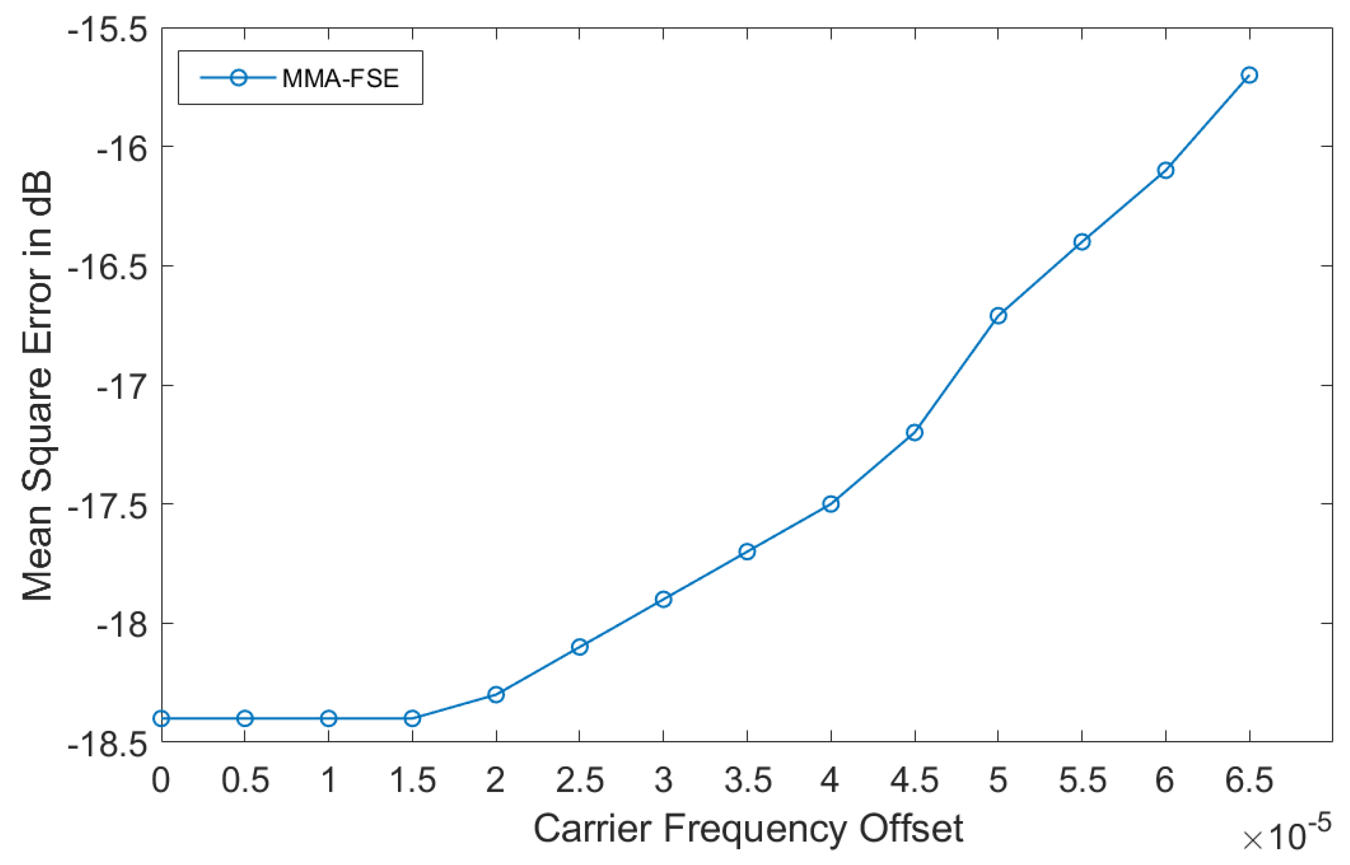
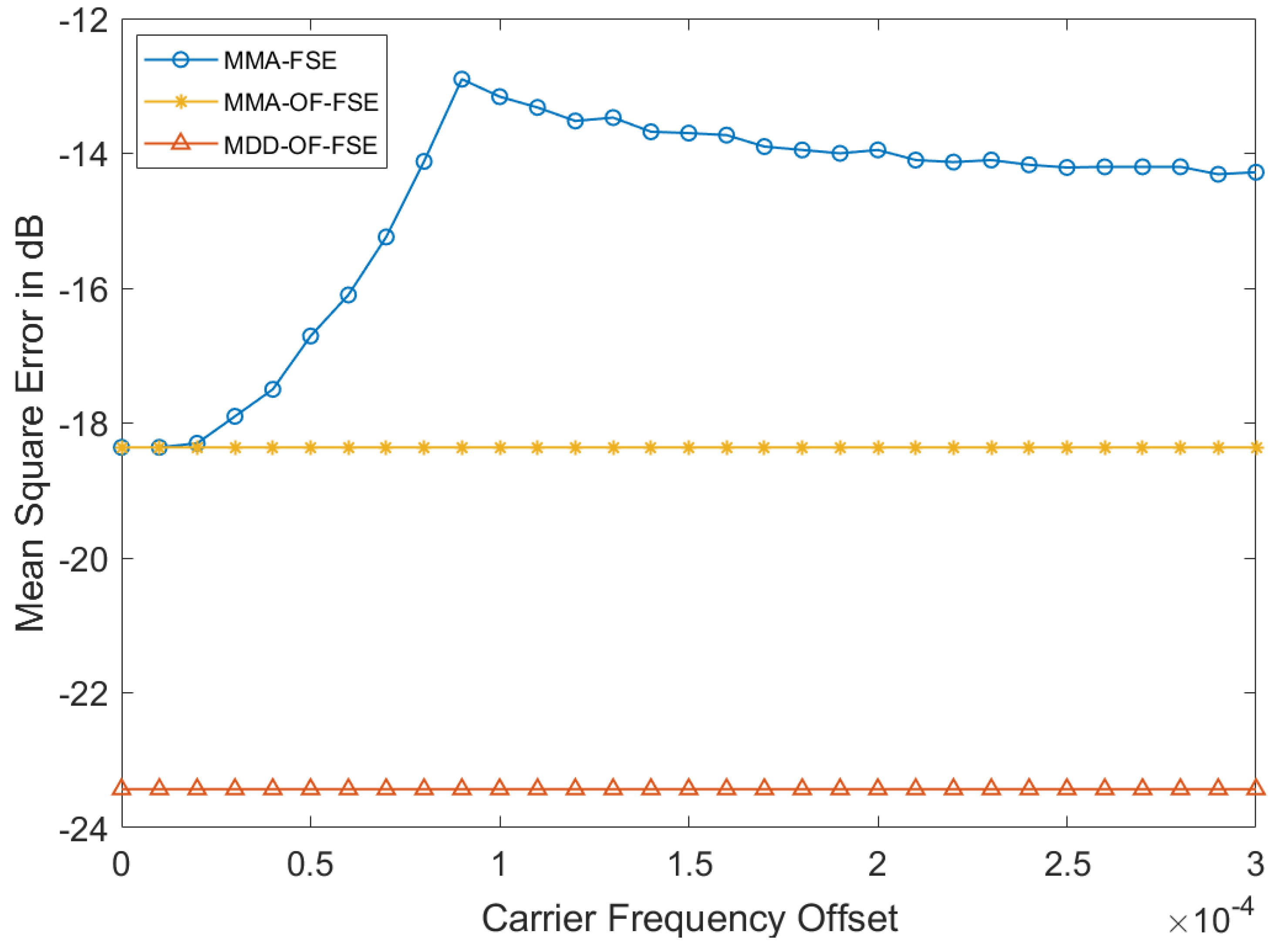
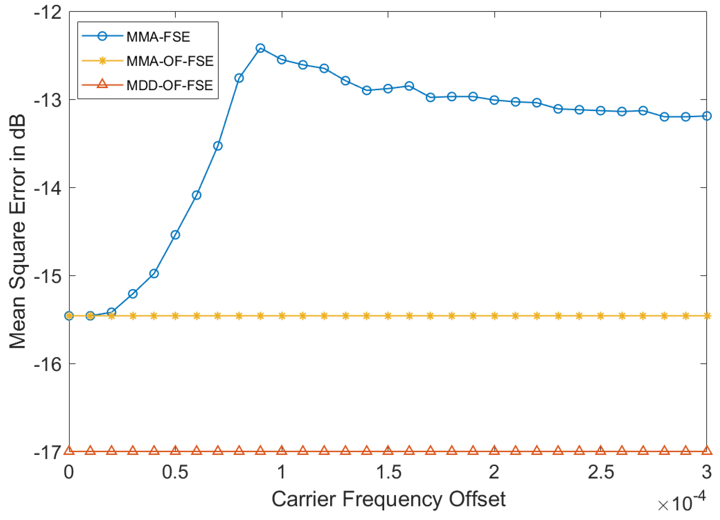
5.1. MMA-FSE Performance with CFO

Figure 5 shows the relationship between the mean square error (MSE) of the MMA-FSE output signal and CFO when Noise Ratio (SNR) is 25 dB. In addition, the MMA-FSE output signal is after carrier synchronization. Through Figure 5, it can be observed that the curve remains unchanged at the initial stage, and then shows an upward trend as the CFO increases. This means that under our parameter conditions, the CFO correction ability of MMA-FSE is approximately Δ f / R = 1.5 × 10 4 , and MMA-FSE performance gradually deteriorates after exceeding this value. Therefore, it is also verified that MMA-FSE cannot solve the impact of CFO on FSE.

5.2. Proposed Algorithm Performance with CFO

Figure 6 and Figure 7 show the MMA-OF-FSE and MDD-OF-FSE performance with the relationship between MSE and CFO when the SNR is 25 dB and 15 dB respectively. For Figure 6, it can be observed that the blue curve trend continues to rise and gradually remains unchanged, it means that the impact of CFO on MMA-FSE tends to stabilize while the curve trends of MMA-OF-FSE and MDD-OF-FSE remain basically unchanged. In addition, it can be noticed that after reaching its worst performance with a CFO of Δ f / R = 0.9 × 10 4 , MMA-FSE performance actually improves as CFO increases. This is because when the CFO is at the critical tracking ability of MMA-FSE, the algorithm will oscillate back and forth between different balanced convergence points, resulting in further deterioration of equalization. After the curves of the three algorithms are stable, it can be observed that the MSE of MDD-OF-FSE is lower by about 5 dB than MMA-OF-FSE, and their performance is much better than MMA-FSE when the curves are stable. There is a similar trend of the curves in Figure 7 when SNR is 15 dB. In addition, the curve trends of the three algorithms all remain basically unchanged under larger CFO by experiments. Therefore, the proposed OF-FSE architecture can effectively eliminate CFO and the improved MD-OF-FSE can improve accuracy further.

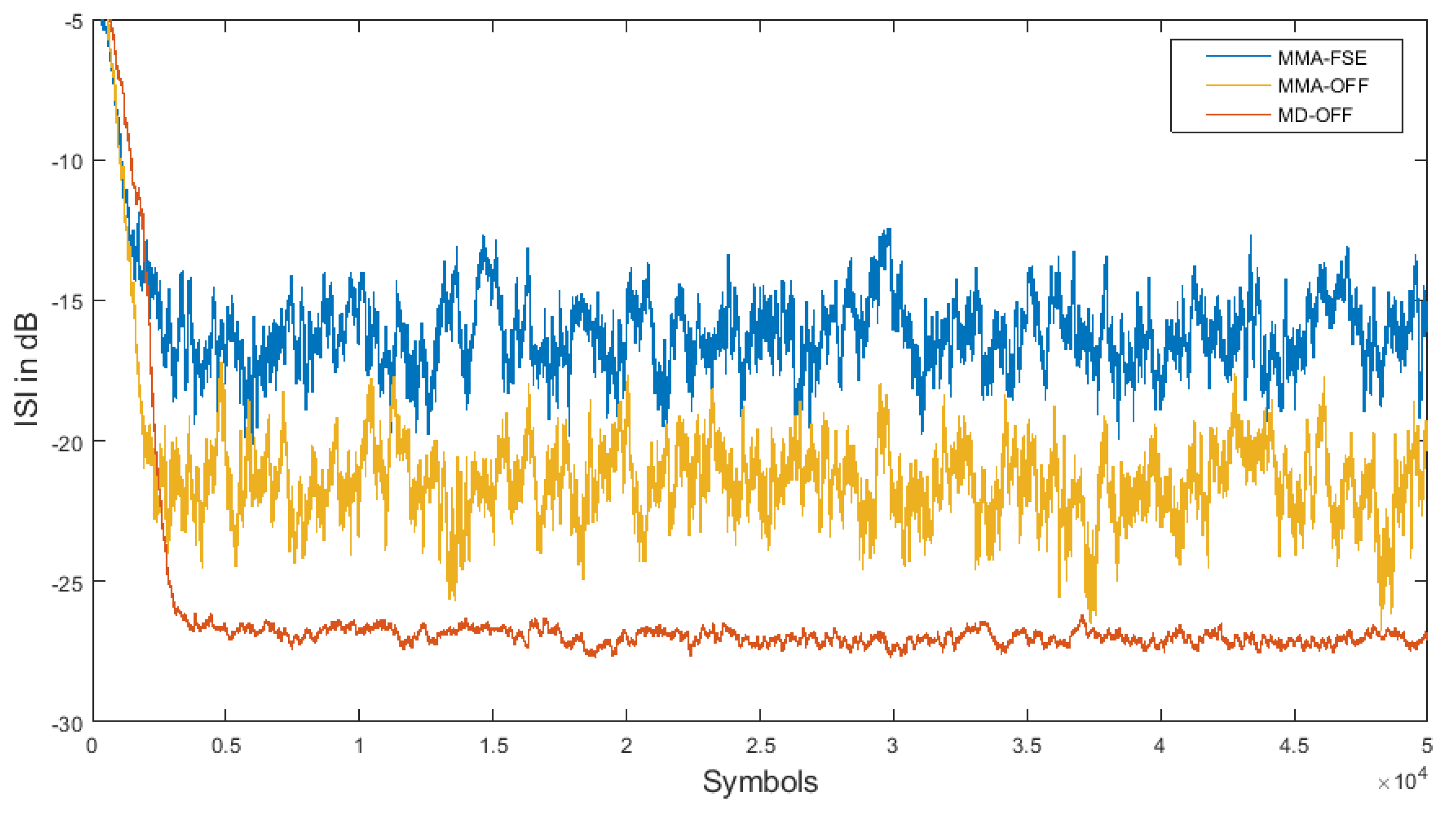
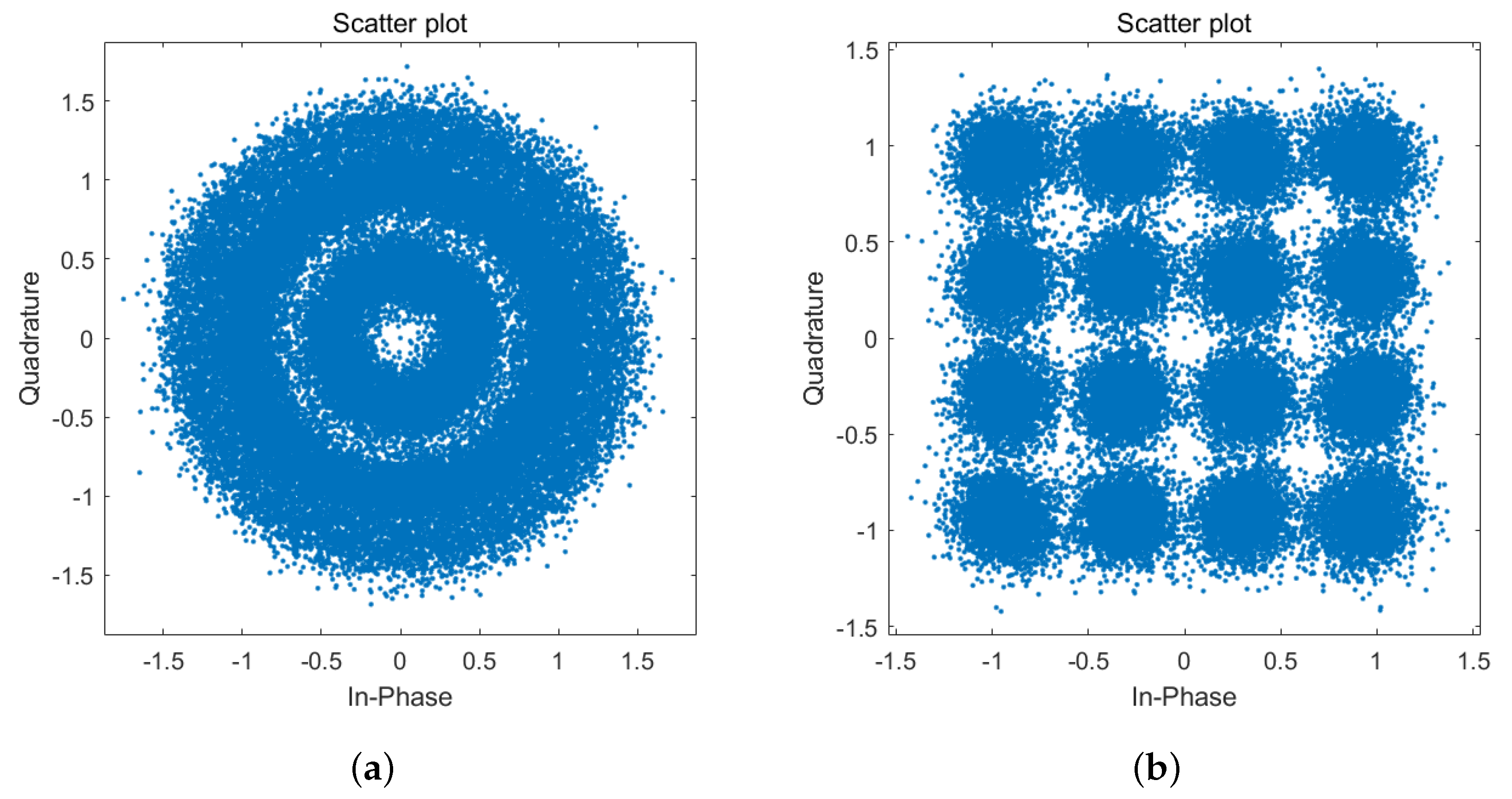
5.3. Algorithms Performance Comparison

The simulation experiments are conducted when CFO is setted to Δ f / R = 0.1 and SNR is 25 dB. Experiments compare the MSE Performance of MMA-FSE, MMA-OF-FSE, and MD-OFF algorithms in Figure 8, the curves represent the trend of MSE as the iterations increase.
Figure 8 shows that under 50,000 iterations, the system output signal MSE of MDD-OF-FSE reaches around −23 dB, which is 5 dB lower than MMA-OF-FSE and 8 dB lower than MMA-FSE. Moreover, the performance of MSE based on MDD-OF-FSE still shows a downward trend when other curves tend to stabilize. It’s obvious that MDD-OF-FSE has better performance and can continuously reduce errors closely to 0.
Under the same parameters, the residual ISI is used as an evaluation indicator to compare the equalization performance of three algorithms, Figure 9 shows the trend of the channel’s remaining ISI as iterations increase. After the three curves converge, our MDD-OF-FSE has the better performance of the channel’s remaining ISI, reaching −27 dB, which is 5 dB lower than MMA-OF-FSE and 9 dB lower than MMA-FSE. Moreover, the curve of MDD-OF-FSE has less jitter after convergence, thus it has stronger stability and more accurate error tracking.
The constellation diagrams of the equalization output signal of MMA-FSE, MMA-OF-FSE, and MDD-OF-FSE are shown in Figure 10a, Figure 11a and Figure 11b, respectively. Our MDD-OF-FSE has tighter constellation points, which means better accuracy. In addition, Figure 10b shows the MMA-FSE output signal after carrier synchronization, our OF-FSE architecture for UAVs is proven to be effective by comparing Figure 10b and Figure 11a. The constellation diagrams further prove our previous discussion and simulations.
Simulation results prove that our OF-FSE architecture for UAVs can effectively eliminate the impact of CFO on equalization and our algorithm MDD-OF-FSE can achieve better steady-state performance.

6. Conclusions

This paper proposed an OF-FSE architecture for QAM-based UAV modulation systems by combining carrier synchronization with an equalizer feedback loop. Thus the CFO of the UAV received input signal is eliminated. Then an MDD algorithm is proposed to further enhance the signal accuracy of UAVs. SimulatiMDD-OF-FSEon results demonstrated that the improved OF-FSE architecture effectively eliminates the CFO of UAVs’ input signal. Furthermore, MDD algorithm reduced the channel’s ISI by 9 dB and MDD-OF-FSE reduced the MSE of the system output signal by 8 dB at 50,000 iterations compared with baseline approaches, our improvements have greatly improved the performance of FSE. Therefore, MDD-OF-FSE has better performance in case of signal quality is poor in UAVs’ modulation systems. In addition, reducing complexity is an unresolved issue. As in the follow-up studies, we will try to propose optimization methods to obtain the optimal filter coefficients while reducing the complexity.

Author Contributions

Conceptualization, L.Z. and Z.W.; methodology, L.Z. and Z.W.; software, L.Z.; validation, L.Z.; formal analysis, L.Z.; writing—original draft preparation, L.Z.; writing—review and editing, G.Z. All authors have read and agreed to the published version of the manuscript.

Funding

This research received no external funding.

Data Availability Statement

Not applicable.

Acknowledgments

The authors would like to thank the anonymous reviewers for their valuable suggestions.

Conflicts of Interest

The authors declare no conflict of interest.

References

  1. Chang, B.; Li, L.; Zhao, G.; Chen, Z.; Imran, M.A. Autonomous D2D transmission scheme in URLLC for real-time wireless control systems. IEEE Trans. Commun. 2021, 69, 5546–5558. [Google Scholar]
  2. Li, Y. A construction of general QAM Golay complementary sequences. IEEE Trans. Inf. Theory 2010, 56, 5765–5771. [Google Scholar] [CrossRef]
  3. Ahmed, S.; Khan, Y.; Wahab, A. A review on training and blind equalization algorithms for wireless communications. Wireless Pers. Commun. 2019, 108, 1759–1783. [Google Scholar] [CrossRef]
  4. Yang, J.; Werner, J.J.; Dumont, G.A. The multimodulus blind equalization and its generalized algorithms. IEEE J. Sel. Areas Commun. 2002, 20, 997–1015. [Google Scholar] [CrossRef]
  5. Maruta, K.; Ahn, C.J. Multi modulus signal adaptation for semi-blind uplink interference suppression on multicell massive MIMO systems. IEICE Trans. Commun. 2021, 104, 158–168. [Google Scholar] [CrossRef]
  6. Sharma, V.; Raj, V.N. Convergence and performance analysis of Godard family and multimodulus algorithms for blind equalization. IEEE Trans. Signal Process. 2005, 53, 1520–1533. [Google Scholar] [CrossRef]
  7. Beiyuan, L.; Chen, G.; Julian, C.; Zhengyuan, X.; Jiajia, L. Blind and Semi-Blind Channel Estimation/Equalization for Poisson Channels in Optical Wireless Scattering Communication Systems. IEEE Trans. Wirel. Commun. 2022, 21, 5930–5946. [Google Scholar]
  8. Hamed, H.; Arman, F.; Behrouz, F. FBMC receiver design and analysis for medium and large scale antenna systems. IEEE Trans. Veh. Technol. 2022, 71, 3044–3057. [Google Scholar]
  9. Yao, G.; Deng, Q.; Ching, P.C.; Ding, Z. Receiver design for OTFS with a fractionally spaced sampling approach. IEEE Trans. Wirel. Commun. 2021, 20, 4072–4086. [Google Scholar]
  10. Li, Q.; Gao, Y.; Gong, F.K.; Li, G.; Zhai, S.H. Efficient frequency-domain linear distortion equaliser in faster-than-Nyquist systems. IET Commun. 2020, 14, 2084–2089. [Google Scholar]
  11. Diliyanzah, A.; Astuti, R.P.; Syihabuddin, B. Dynamic CFO reduction in various mobilities based on extended Kalman filter for broadband wireless access technology. In Proceedings of the 2014 6th International Conference on Information Technology and Electrical Engineering (ICITEE), Yogyakarta, Indonesia, 7–8 October 2014; pp. 1–6. [Google Scholar]
  12. Yuan, J.T.; Tsai, K.D. Analysis of the multimodulus blind equalization algorithm in QAM communication systems. IEEE Trans. Commun. 2005, 53, 1427–1431. [Google Scholar] [CrossRef]
  13. Ojeda, O.A.Y.; Grajal, J. The relationship between the cyclic wiener filter and fractionally spaced equalizers. IEEE Trans. Signal Process. 2019, 67, 4333–4341. [Google Scholar] [CrossRef]
  14. Li, D.; Wang, J.; Lu, H.; Jin, J. Performance improvement of multi-carrierless amplitude and phase modulation based visible light communication system using fractionally spaced equalizer. In Proceedings of the Optics Frontiers Online 2020: Optical Communications and Networks, Online, 24–25 July 2020; Volume 11604, pp. 110–113. [Google Scholar]
  15. Mayyala, Q.; Abed-Meraim, K.; Zerguine, A.; Lawal, A. Fast Multimodulus Blind Deconvolution Algorithms. IEEE Trans. Wirel. Commun. 2022, 21, 9627–9637. [Google Scholar] [CrossRef]
  16. Slock, D.T.; Papadias, C.B. Blind fractionally-spaced equalization based on cyclostationarity. In Proceedings of the IEEE Vehicular Technology Conference (VTC), Stockholm, Sweden, 8–10 June 1994; pp. 1286–1290. [Google Scholar]
  17. Yuan, J.T.; Chao, J.H.; Lin, T.C. Effect of channel noise on blind equalization and carrier phase recovery of CMA and MMA. IEEE Trans. Commun. 2012, 60, 3274–3285. [Google Scholar] [CrossRef]
  18. Gardner, F. A BPSK/QPSK timing-error detector for sampled receivers. IEEE Trans. Commun. 1986, 34, 423–429. [Google Scholar] [CrossRef]
  19. Sarkar, B. Phase error dynamics of a first-order phase locked loop in the presence of cochannel tone interference and additive noise. IEEE Trans. Commun. 1990, 38, 962–965. [Google Scholar] [CrossRef]
  20. Nowlan, S.J.; Hinton, G.E. A soft decision-directed LMS algorithm for blind equalization. IEEE Trans. Commun. 1993, 41, 275–279. [Google Scholar] [CrossRef]
  21. Li, J.; Feng, D.Z.; Zheng, W.X. A Robust Decision Directed Algorithm for Blind Equalization Under alpha-Stable Noise. IEEE Trans. Signal Process. 2021, 69, 4949–4960. [Google Scholar] [CrossRef]
  22. Oh, K.N.; Chin, Y.O. Modified constant modulus algorithm: Blind equalization and carrier phase recovery algorithm. In Proceedings of the Proceedings IEEE International Conference on Communications ICC’95, Seattle, WA, USA, 18–22 June 1995; Volume 1, pp. 498–502. [Google Scholar]
Figure 1. General MMA-FSE architecture of QAM-based UAV modulation systems.
Drones 07 00525 g001
Figure 2. System model of MMA based on OF-FSE architecture for UAVs.
Drones 07 00525 g002
Figure 3. Phase tracking characteristic model of MMA-OF-FSE.
Drones 07 00525 g003
Figure 4. System model of MDD for OF-FSE architecture.
Drones 07 00525 g004
Figure 5. MSE performance of MMA-FSE versus CFO.
Drones 07 00525 g005
Figure 6. MSE of three algorithms trends as CFO increase when SNR is 25 dB.
Drones 07 00525 g006
Figure 7. MSE of three algorithms trends as CFO increase conducted whens 15 dB.
Drones 07 00525 g007
Figure 8. Algorithms systems’ output signal performance comparison when SNR is 25 dB.
Drones 07 00525 g008
Figure 9. Residual ISI comparison.
Drones 07 00525 g009
Figure 10. Constellation diagrams for MMA-FSE. (a) equalization output signal; (b) system output signal after carrier synchronization.
Drones 07 00525 g010
Figure 11. Constellation diagrams for OF-FSE architecture. (a) MMA-OF-FSE; (b) MDD-OF-FSE.
Drones 07 00525 g011
Table 1. Notation Definition.
SymbolDefinition
s ( n ) System input signal
hChannel impulse response
l h Length of channel impulse response
v n Gaussian white noise
r ( n ) Received signal
f ( n ) Filters coefficients
y ( n ) Equalizer output signal
z ( n ) System output signal
POversampling multiple
TSampling interval
J ( n ) Cost function
e ( n ) Error function
ξ ( k ) Phase characteristic of loop
f d Phase Angular frequency
Δ f Frequency deviation
r ^ ( n ) Equalizer input signal
y ^ ( n ) Decision value of y ( n )
F 1 First-order loop filtering characteristic
F 2 Second-order loop filtering characteristic
K 1 Phase discrimination characteristic of first-order loop
K 2 Phase discrimination characteristic of second-order loop
ρ Integral parameter
H ( z ) Amplitude-frequency response of the channel
θ α ( k ) Tracking phase of MMA
θ β ( k ) Tracking phase of MMA-OF-FSE
θ ϕ ( k ) Phase of MMA-OF-FSE input signal
θ ^ 1 ( k ) Phase errors of first-order loop output
θ ^ 2 ( k ) Phase errors of second-order loop output
μ Equalization iteration
λ ( n ) Adaptive factor of MDD algorithm
μ λ Updating step size of adaptive factor λ ( n )
Disclaimer/Publisher’s Note: The statements, opinions and data contained in all publications are solely those of the individual author(s) and contributor(s) and not of MDPI and/or the editor(s). MDPI and/or the editor(s) disclaim responsibility for any injury to people or property resulting from any ideas, methods, instructions or products referred to in the content.

