1. Introduction
Carrier-based unmanned aerial vehicles (UAVs) are becoming increasingly important because they can take the place of pilots to perform dangerous tasks in maritime activities. However, the carrier landing is one of the most critical problems faced by the carrier-based UAVs. Throughout the landing process, UAVs should tightly follow the glide slope while maintaining the approaching speed to land on a fixed narrow touchdown area. Combined with terrible marine environmental conditions, such as air wake and the risky deck motion, the performance requirements of the landing become extremely difficult to be satisfied.
Since 2014, the maritime augmented guidance with integrated controls for carrier approach and recovery precision enabling technology (“Magic Carpet”) project has been carried out. By introducing direct lift, the decoupling of aircraft trajectory and attitude is realized, greatly reducing the burden on pilots. References [
1,
2] analyzed the key technologies and control structure of the “Magic Carpet” and realized the decoupling of attitude and trajectory by introducing direct lift generated by deflection of the flap actuator. Reference [
3] introduced the development status of fully automatic landing and “Magic Carpet” landing and indicated that the “Magic Carpet” landing structure is in the direction of future development. Reference [
4] introduced the modeling expression under direct lift carrier landing control in detail. Based on the conventional carrier-based aircraft dynamics model, direct lift flap channel authority should be introduced. Reference [
5] analyzed the control structure ideas of three modes of direct lift and two modes of direct lift force in detail and applied active disturbance rejection instead of PID to design the two modes, so as to realize the observation and compensation of interference. Reference [
6] proposed a two-layer parallel dynamic inverse control framework to design an accurate landing path control scheme based on direct lift, which met the landing path control requirements. Reference [
7] proposed a new integrated direct lift control method to improve the control performance of fixed-wing aircrafts in response to guidance instructions. Reference [
8] designed a longitudinal direct lift flight control system based on radial basis neural network adaptive control and verified the effectiveness and accuracy of the 6-DOF nonlinear aircraft model controller.
Considering the optimization of landing control quality, the most direct idea is to optimize landing control parameters. In the field of parameter optimization algorithms, the Z–N algorithm was adopted in reference [
9] to optimize the traditional control law. With the development of swarm intelligence algorithms, this class of algorithms is mostly used to optimize the control parameters. Reference [
10] used particle swarm algorithms for the parameter optimization of control laws. In addition, intelligent optimization methods such as neural networks were also used in references [
11,
12] to optimize the control parameters. However, there is little research on parameter optimization in the field of carrier landing control. Reference [
13] proposed an explicit model predictive control method based on the extended pigeon swarm optimization algorithm and applied it to attitude controller design to solve the parameter optimization problem of the designed controller. Reference [
14] proposed a control law parameter optimization design method for landing point distribution. Considering the influence of various disturbances on landing point distribution comprehensively, the particle swarm optimization algorithm was used to optimize the design and obtain the control law parameters with high disturbance immunity performance. In reference [
15], a genetic algorithm was used to optimize the control parameters of the flight control system, and finally, the flight control system was verified to exhibit good robustness through simulation.
Since carrier-based UAVs have multiple control surface actuators, control allocation is also applied to the carrier landing control field. In reference [
16], nonlinear state error feedback law and real-time disturbance compensation were adopted to calculate virtual control quantity, and the elevator and engine thrust control quantity were obtained through control allocation. Reference [
17] comprehensively analyzed the control strategy of “Magic Carpet” technology. From the perspective of direct lift decoupling control of track adjustment and attitude maintenance, the reasonable weighted pseudo-inverse control distribution method was adopted to realize the rudder surface distribution of direct lift. Reference [
18] took into account the fact that there are many control surfaces of the controlled object. Based on the weighted pseudo-inverse method, output was reasonably allocated to each rudder surface to reduce resource waste. Reference [
19] proposed an improved non-dominated genetic optimization algorithm to establish the non-dominated relationship curve of optimal control among various rudder surfaces of the ship landing system and realize control allocation. In reference [
20], based on the pseudo-inverse control distribution algorithm, the control input of the robust foresight controller was redistributed to the effective rudder surface, so as to realize fault-tolerant control under unknown faults. Reference [
21] proposed a direct lift carrier landing control method based on a feature structure configuration decoupling design to realize the decoupling of long-period modes and short-period modes of aircraft longitudinal motion, as well as the decoupling of the throttle channel and longitudinal rod channel.
In the field of carrier landing control, the optimization of control parameters and control assignment of multiple control surfaces are the key problems in the landing control technology based on direct lift. In the field of control parameter optimization, the control gain optimization results under the baseline condition are usually used as off-line nominal parameters [
11]. However, in the process of carrier landing, there are unknown complex environmental interferences, such as air wake, and the applicability of off-line optimization of nominal parameters is poor, resulting in insufficient robustness. At present, the pseudo-inverse method is mainly used for control allocation in the field of landing control [
21]. However, when it comes to direct lift landing control, there is a significant difference in rudder efficiency for direct lift control and angle-of-attack maintenance. The single optimization index of the pseudo-inverse method is unable to carry out perceptual optimization for different rudder requirements scenarios, and there is a problem of insufficient dynamic characteristics of control allocation.
Aiming at the above problems, this paper presents a direct lift landing control approach by utilizing the control performance index intelligent optimization and dynamic optimal allocation method. The direct lift control (DLC) scheme is used to enhance the control maneuverability by introducing flap channels and to achieve rapid correction of vertical disturbances. Furthermore, to improve the control performance, the intelligent optimization method of DLC gain for landing control performance is proposed, and the neural network relationship between parameter uncertainty and optimal DLC gain is established. In addition, by utilizing the recursive least-squares identification method, the uncertain parameters can be real-time estimated; hence, the optimal DLC commands can be generated online by the established neural network, and the generated control commands are allocated to multiple actuators of carrier-based UAVs using the dynamic optimal allocation algorithm. Finally, the superiority of the method is verified with simulation comparison.
The rest of this paper is organized as follows:
Section 2 describes the dynamics and environmental modeling of the carrier-based UAV. In
Section 3, the DLC scheme is proposed to enhance the control maneuverability. The intelligent optimization method of DLC gain is proposed in
Section 4, including the neural network training and the online aerodynamic identification parts. In
Section 5, the design method of dynamic optimal control performance allocation is given to realize the multi-control surface control allocation. The comparative simulations verification is shown in
Section 6, and the conclusions are given in
Section 7.
2. Modeling of UAV Flight Dynamics and Carrier Landing Environment
The carrier-based UAV is a complex controlled object with nonlinear, multivariable, strong coupling characteristics. In the process of carrier landing, it will also be strongly interfered by environmental factors such as deck motion and air wake [
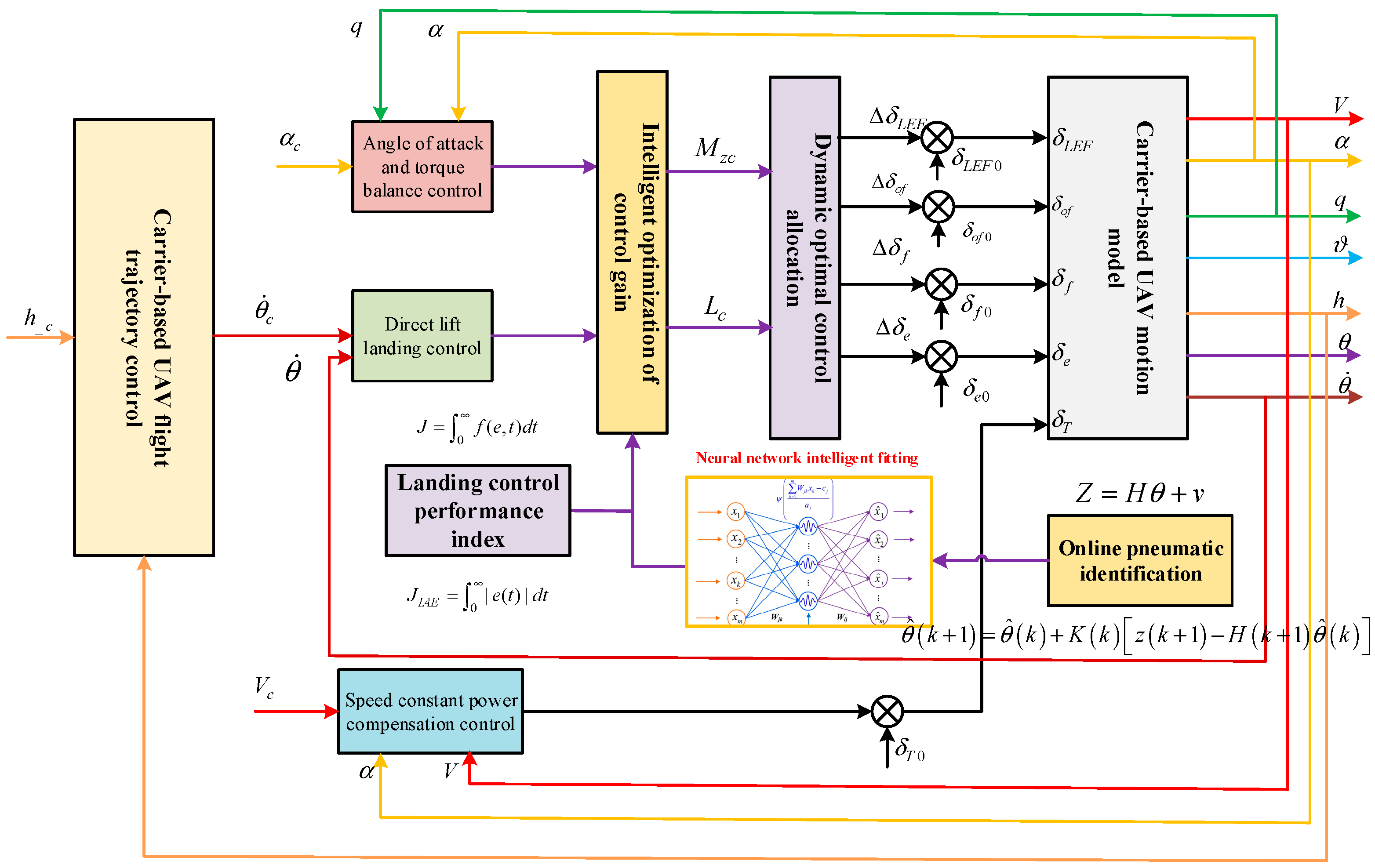
22]. The carrier-based maneuvering mechanics and environmental modeling based on direct lift are shown in
Figure 1, including the establishment of the carrier-based maneuvering mechanics model, deck motion model and air wake interference model.
2.1. Flight Dynamics Modeling of Carrier-Based UAV during Landing
Different from the traditional landing idea, in the designed direct lift carrier landing control system, it is necessary to introduce the control authority of the flap channel aerodynamic control surface to establish the nonlinear dynamics model of carrier-based UAVs.
The table of variables and units is shown in
Table 1.
The longitudinal motion of carrier-based UAVs is described as follows:
,
,
and
are the lift, drag, pitching moment and engine thrust, as follows:
Considering the influence of air wake on carrier-based UAVs to obtain the state space model as follows:
Among them, , and are the sum of horizontal wake and vertical wake flow of deck wind. , , are state matrix, the control matrix and the matrix perturbation, respectively.
2.2. Environmental Modeling of Carrier-Based UAV Landing Process
The carrier keeps moving during the approaching and landing process of UAVs. The movement of the carrier on the sea surface is affected by the air flow and wave movement. The movement of a UAV carrier on the sea surface is divided into translational motion and rotational motion, among which the translational motion includes heave, sway and surge, and the rotational motion includes pitch, roll and yaw.
Because the UAV carrier is affected by the sea wave movement, the UAV carrier movement also has a great impact on the approach and landing of carrier-based UAVs. The real UAV carrier motion is a complex random process, which cannot be described with a deterministic function, but can be approximated under given conditions, namely:
Type: for carrier heaving motion and for carrier pitching motion. , , , , for Sine amplitude and , , , for Sine angular frequency.
The air wake is mainly divided into four components, and each component is decomposed into coordinate axis components, according to the coordinate system. Then, various axis components are added together to acquire the real stern current situation. The horizontal and vertical directions mainly affect the longitudinal motion state of carrier-based UAVs, and the lateral wake mainly affects the lateral motion state of carrier-based UAVs [
23].
Turbulent component of free atmosphere: , , ;
Rooster wake: , ;
Periodic component of wake: , ;
Random component of wake: , , .
where
,
,
are the horizontal wake, transverse wake and vertical wake flows of the air wake, respectively.
4. Online Intelligent Optimization of DLC Gain Based on Performance Index
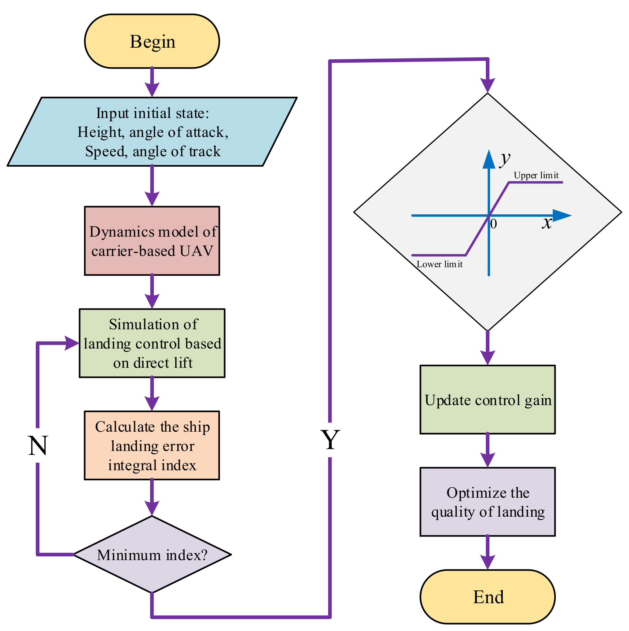
Firstly, the intelligent optimization design of direct lift control gain based on performance indexes requires designing the direct-lift-based landing controller on the ground, performing multiple simulations on the ground, optimizing control gain by off-line simulation and based on performance indexes, calculating aerodynamic derivatives based on the off-line model while pulling off the aerodynamic derivatives on the ground, using the same approach to perform a large number of simulations under this condition, and performing off-line direct lift control gain optimization based on control performance indexes. The off-line direct lift control gain was optimized based on the control performance index. The optimal direct lift control gain was determined according to the deviation of the aerodynamic derivative both under pull-off condition and without pull-off condition. The derivatives included angle-of-attack derivative, elevator derivative and flap derivative. The mapping relationship between the aerodynamic derivative deviation and control gain was determined, and the control gain optimization direction and strategy were determined to achieve control gain optimization.
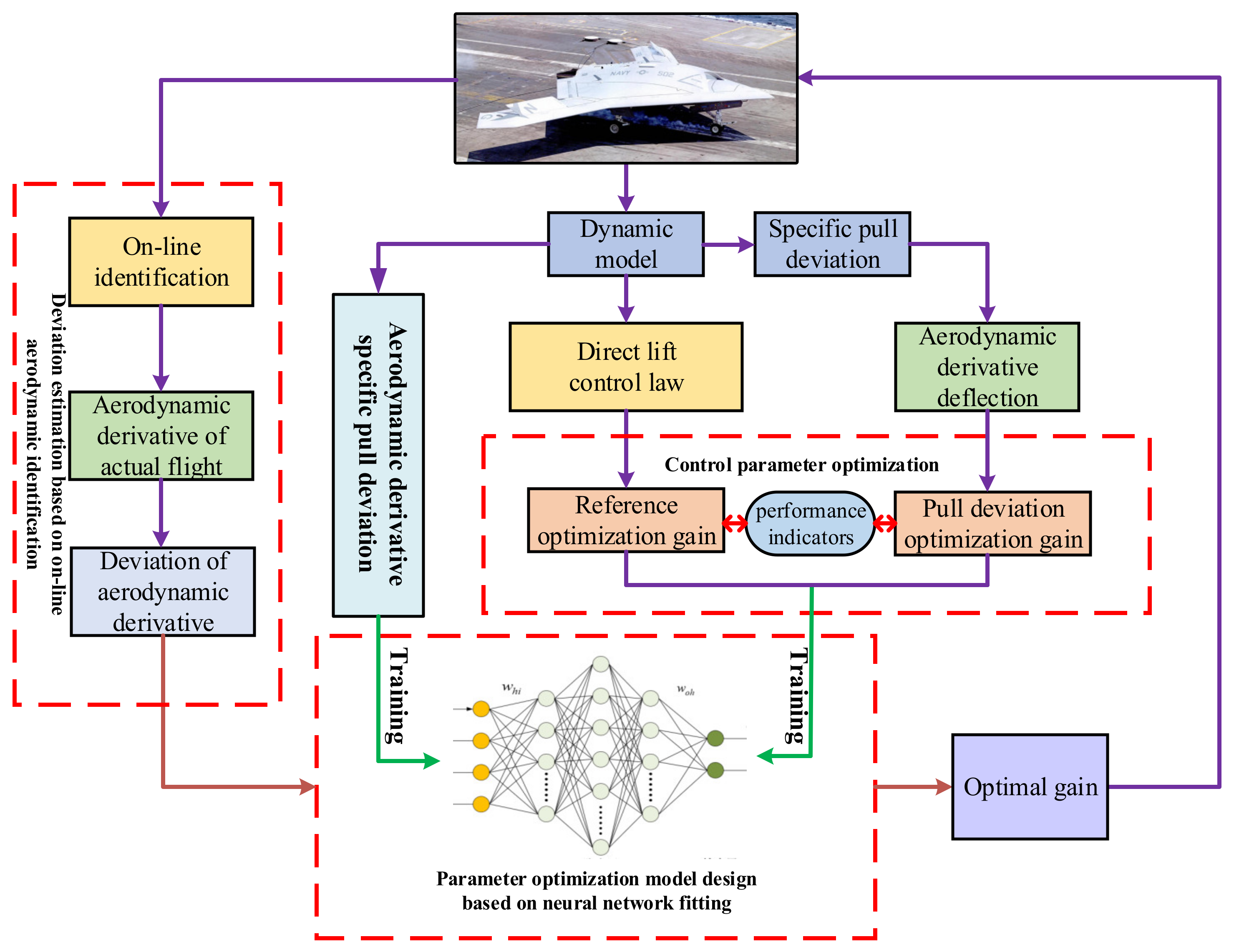
The basic steps of the intelligent optimization method of direct lift control gain based on performance index are shown in
Figure 5.
(1) According to the landing control law based on direct lift, a large number of off-line simulations are carried out, and the optimal control gain of direct lift is determined based on landing performance indexes. On this basis, the relevant aerodynamic derivative of the corresponding lift coefficient is calculated.
(2) The off-line aerodynamic model of carrier-based UAVs is modified; the aerodynamic derivative is handled with pulling and deviation; and the optimal direct lift control gain is found based on the control performance index for each pulling and deviation condition.
In the process of off-line identification of the undetermined coefficient, it is not a pulled deviation. The control gain obtained by index screening is called “Standard Optimization Gain”, and the control gain obtained by index screening is called “Pull-deviation Optimization Gain” after different kinds and degrees of pull–deviation processing. The design principle of gain optimization strategy is based on the relationship between aerodynamic derivative pull level and optimal control gain.
(3) The deviation of the aerodynamic derivative is determined by comparing the deviation of the aerodynamic derivative with that of no deviation. The optimal direct lift control gain deviation corresponding to each deviation is corresponded to form a neural network mapping relationship between the deviation of the aerodynamic derivative and the optimal direct lift control gain deviation. It is necessary to carry out specific pulling and deviation processing for aerodynamic derivatives and select the optimal control gain after pulling and deviation through the index. On the basis of obtaining a large quantity of data, a neural network model is established for learning and training.
(4) According to the actual landing flight states, the corresponding aerodynamic derivative is identified and compared with the aerodynamic derivative of the ground reference model. The corresponding deviation is calculated and solved by the gain optimization neural network to determine the direction and amplitude of the gain adjustment.
The aerodynamic model is determined by off-line identification. Based on this model, the control law based on direct lift is designed, and the optimal control gain is selected using the gain optimization method based on performance index. The optimal control gain is also selected by the same gain optimization method by pulling and deflecting the aerodynamic derivative.
4.1. Optimization of Landing Control Gain Based on Performance Index
The optimization method of high-precision direct lift carrier landing control gain is shown in
Figure 6.
Firstly, the evaluation quality index system of the controller needs to be established. Then, gain optimization is carried out through a large number of simulations [
26]. Control gain optimization is carried out according to the indexes required in this study. In the field of controller design, there are a series of landing control performance indexes, which are mainly divided into two categories: time domain indexes and frequency domain indexes. Time domain indexes include, generally, rise time
, adjust time
and overshoot of performance indicators
%. Frequency domain indexes include, generally, angle margin PM and amplitude margin AM. Further, control performance index is a series of comprehensive indexes.
Landing control performance requires fast response and high precision. It is difficult to measure the control quality simply by using adjustment time or overshoot, so better error integral criteria should be adopted. The error integral criterion is a kind of performance index. When the actual output of the control system does not meet the requirements of the specified output, it is used to integrate the difference between them or integrate the deviation between the specified transmission signal and the feedback signal of the system transfer function. It is a criterion to judge the control performance of the system by integrating the results [
12]. Calculated according to the controller in the whole process of regulating the amount of input, output deviation
, within the scope of the integral error integral criterion expression is the objective function, the mathematical expression is
In order to accurately evaluate error signals in the landing control process, this direct lift control gain optimization method based on performance index adopts absolute deviation integral criterion/IAE performance index which can measure errors in dynamic processes.
According to the selected landing control performance index, the landing control structure based on direct lift is simulated and the corresponding data are recorded. Based on the corresponding data, the corresponding landing control performance indicators are calculated, the control gain is changed and the same landing control simulation is carried out. By comparing all the landing control performance indicators calculated by simulation, the direct lift carrier landing control gain under the optimal performance index is selected. Finally, the optimization gain is substituted into the landing control based on direct lift to realize the optimal landing control, and the quality of landing control is optimized.
4.2. Control Gain Optimization Model Design Based on Neural Network
In this study, it is necessary to establish a relationship between the aerodynamic derivative and corresponding direct lift optimal control gain. The BP network is adopted in this work, which has a multi-layer feedforward network trained according to the error back-propagation algorithm in addition to a feedforward neural network. The BP network can learn and store a large number of input–output mode mapping relationships without revealing the mathematical equations describing the mapping relationships in advance. Its learning rule is to use the fastest descent method and constantly adjust the weight and threshold of the network through back propagation to minimize the sum of squares of error of the network [
11].
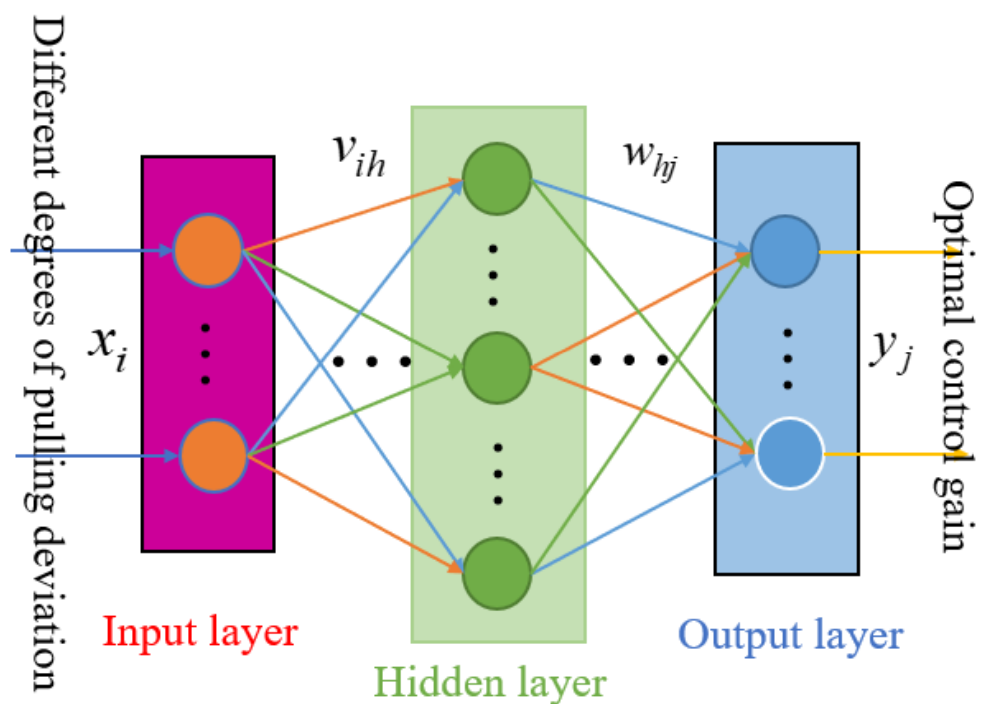
The basic structure of the BP neural network is shown in
Figure 7. The BP neural network structure includes the input layer, hidden layer and output layer, and the neural network learning method is as follows:
Set the weight from the input layer to the hidden layer as , and set the threshold of the nerve of the hidden layer as . The weight from the hidden layer to the output layer is set as , and the threshold value of the nerve in the output layer is represented by . There are input neurons, hidden neurons, hidden nerve thresholds and output neurons, so there are output nerve thresholds, and is the learning efficiency.
The standard training process of the gain optimization learning network is mainly divided into forward and reverse processes. Firstly, the forward propagation of the signal is calculated from the input layer to the hidden layer, and then the corresponding value is calculated from the hidden layer to the output layer. Then, through the reverse propagation of errors, it returns from the output layer to the hidden layer, calculates the corresponding value, and then from the hidden layer to the input layer, it slowly trains the hidden layer to the weight and threshold changes in the output layer and the weight and threshold changes in the input layer to the hidden layer [
27].
According to the chain derivative rule, we obtain the following formula:
The structure of the gain optimization learning network and the training and testing processes are shown as follows:
(1) Determine the structure of the neural network, take the aerodynamic derivative as the input of the neural network and take the optimization control gain as the output of the neural network. The structure of the neural network is 3-2-4-1, and the learning efficiency is 0.1.
(2) Put 90% of total data into the neural network as training data to generate the gain optimization learning network.
(3) A total of 10% of the total data is taken as the test set for model test. The model is evaluated by analyzing the absolute error and relative error indexes.
(4) The neural network is saved, and then the optimal control gain can be obtained through the online identification of aerodynamic derivatives.
4.3. Control Gain Optimization Based on Online Aerodynamic Identification
In the landing process based on direct lift, there are a lot of uncertainties. Therefore, the aerodynamic derivative of the landing carrier-based UAV will have a certain degree of pull and deviation interferences in the air [
28]. Gain optimization can be realized through an off-line fitting gain optimization learning network.
Before the application of an off-line fitting gain optimization learning network, this study needs to carry out the online aerodynamic identification of carrier-based UAVs, identify the corresponding aerodynamic derivative online, calculate the deviation by difference with the ground reference model, bring the off-line fitting optimal control gain optimization model and obtain the corresponding optimal control gain.
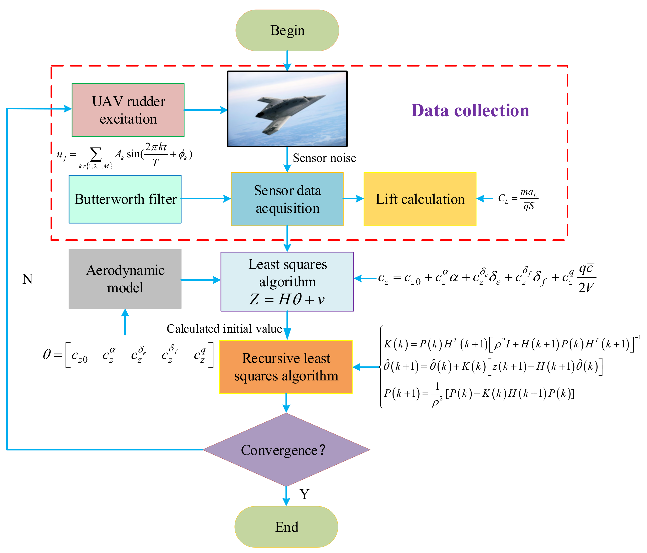
In this study, the aerodynamic derivative is obtained using the recursive least-squares identification method. The recursive least-squares method does not need to recalculate the information matrix every time the data are updated, but does need one initial value to realize online recursion, which reduces the calculation amount and improves the calculation efficiency. In addition, by introducing the forgetting factor into the recursive formula, the time-varying parameters can be estimated, but the fixed parameters need not be.
The process of recursive least-squares identification is shown in
Figure 8.
For parameter estimation, the relationship between the measured output and the model parameters is more important. If the output is given by the following equation, then the model is called a linear parameter model.
Assuming that it knows the matrix
, the measurement equation can be expressed as
including
is using the lift-formula-calculated values;
for set modeling functions;
for identification model; and
for residual.
Using least-squares method in the form of the model, any uncertainty about
and
, that is not about the probability of
and
, was not used. Least-squares estimate can be obtained by a deduction:
and
given that the “best” estimate is achieved by making the measuring output and model output weighted sum of error square between the minimum and concluded.
Generally speaking, with the continuous increase in observation information, the accuracy of the estimated value will become higher and higher and tend to be stable, which is also one of the means to test the accuracy of the estimated value. As the number of observations increases, so does the amount of work, and as you can see from the analysis below, the previous calculation is repeated because all the information is needed for each calculation. To overcome this shortcoming, the recursive least-squares method is introduced. The method has fast convergence, high identification efficiency, the accuracy is the same as that of ordinary least squares and the identification accuracy basically meets the engineering requirements.
To use recursive least-squares method, we first need to use the known observations and outputs to calculate the initial value needed for a recurrence.
Before
moment all the observations and output are known, the record
estimates parameters for before
time.
If the measurement noise variance for
, then estimate the covariance matrix for
Record the information matrix is .
Note: provide the initial value,
, recursive from
moment recursive:
The above three formulas show the process of the recursive least-squares method. For the determination of estimated parameters as the amount of unbiased estimation,
. To obtain it:
Obtain the estimate
corresponding to the covariance matrix of
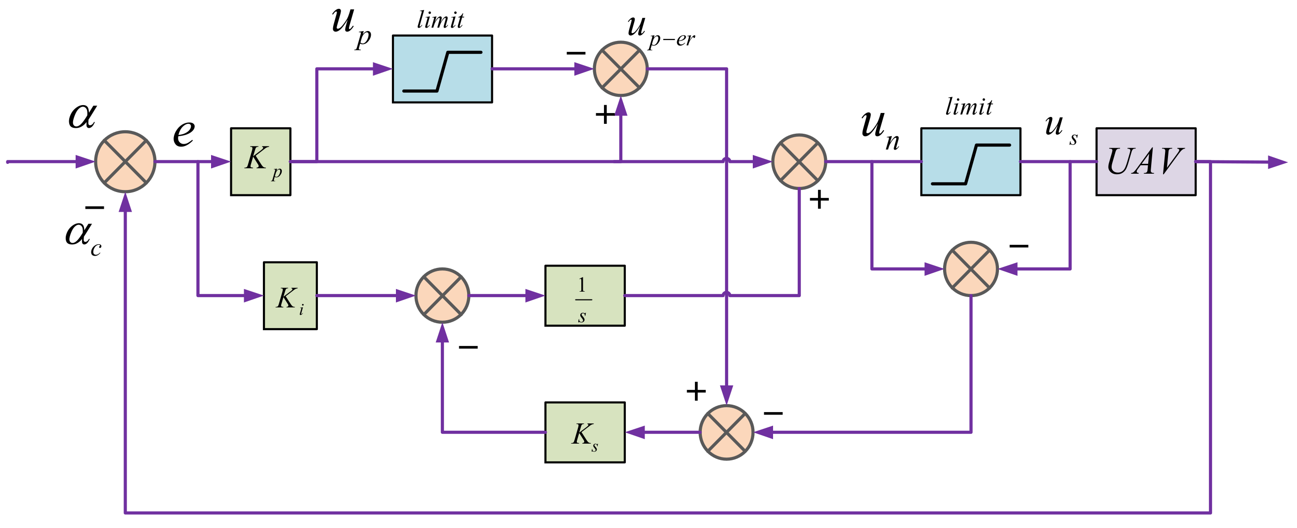
In the process of actual use, with the increase in information, the positive quality of the information matrix decreases continuously, and the improvement effect on new information is gradually equal to zero, which is called the data saturation phenomenon. To solve this problem, a recursive method introducing a forgetting factor is proposed, and the recursive least-squares formula is replaced by
Since carrier-based UAVs are susceptible to atmospheric disturbances during landing, in order to simulate the real situation of carrier-based UAVs during landing, a large number of pull-off simulations are required in general flight control simulations to test and evaluate the controller. By introducing a certain degree of random pull-off parameters, simulation is carried out using the Monte Carlo method. The divergence of simulation results is used to judge the rationality of the optimization gain, and the robustness of the optimization gain is evaluated.
5. DLC Allocation Method Based on Dynamic Optimization
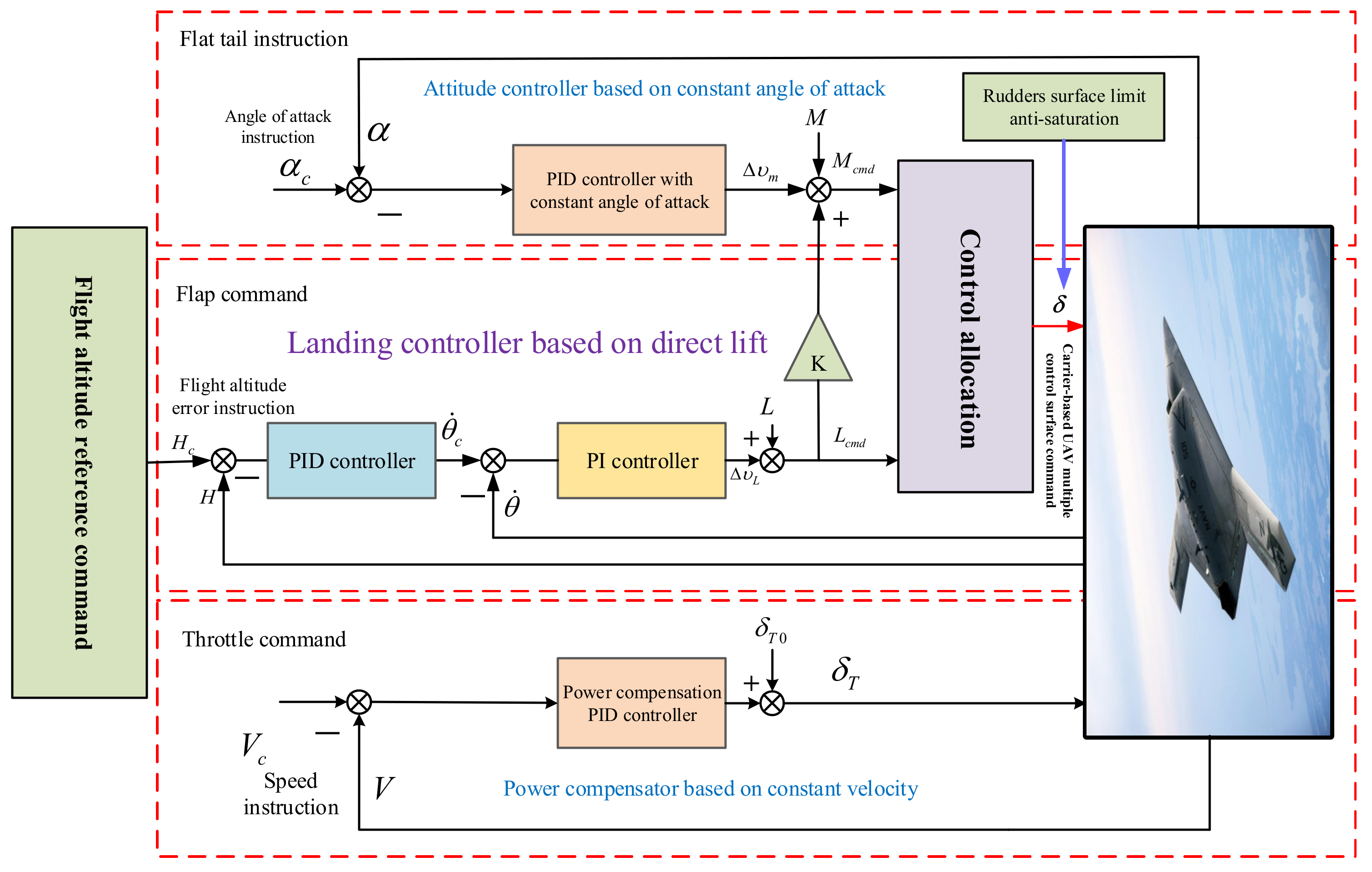
As shown in
Figure 9, in the landing control structure based on direct lift, incremental force and moment commands are generated by the direct lift control law and angle-of-attack control law, and the required force and moment commands are obtained by combining the incremental force and moment with the current force and moment, which are then distributed to other carrier-based UAV multi-control surface actuators using dynamic optimal control [
29].
Among them, the input of the control allocation module is moment and direct lift, the output is elevator , leading edge flap , trailing edge flap and outer leading edge flap rudder surface deflection. The elevator, leading edge flap, trailing edge flap and outer leading edge flap all have lifting ability. The elevator has pitching trim ability. Besides lifting, the outer leading edge flap also participates in roll control, so it belongs to the dual channel multiplex rudder surface.
Following, is a mathematical description of the control allocation problem:
The landing control of carrier-based UAVs mainly considers the requirements of direct lift, pitch steering moment and roll steering moment. The virtual control amount is
The control efficiency matrix is
The rudder needs to go through a certain dynamic response process to execute the command, and the rudder deviation signal given can not be reflected on the steering gear in time. The direct lift has the characteristics of fast speed and short response time. A dynamic control allocation algorithm based on quadratic programming was designed to take distribution error as an optimization objective and introduce a dynamic optimization objective considering task scenarios and actuator execution speed.
Type
for the proportion of dynamic optimization items based on task scenario and executing mechanism in the total optimization objective;
and
are weighted coefficient matrix;
for dynamic coefficient and
, reflected in the decline in the ship dynamic weighting process which directly lifts control instruction; and
and
are the extraction matrix of the rudder surface, as follows:
Type for rudder surface coefficient. The takes one; , and carry out normalized assignment, according to the deflection rate of the corresponding rudder surface, and assign a relatively large value to the slow deflection rate, which makes the focus of consideration when minimizing the deflection of the rudder surface.
For the upper and lower limits,
and
, of the optimization problem, the comprehensive quantity of the rudder position constraint and the deflection rate constraint are taken, namely
To sum up, the dynamic control allocation method based on quadratic programming designed in this paper firstly considers the minimization of control allocation error to improve the allocation accuracy. Secondly, the minimization of the rudder deflection is considered to reduce the loss of each actuator. In the process of rudder surface deflection minimum, dynamic coefficient is introduced; namely, when the angle of attack is maintained, the flap deflection related to direct lift is minimized. When the trajectory angle tracking is focused, the deflection of the flat tail related to torque is minimized. At the same time, the rudder surface coefficients , , and are introduced; namely, priority is given to minimizing rudder surfaces with slower deflection rates.
6. Simulation Analysis
This section provides the simulation results to demonstrate the effectiveness and advantages of the proposed approach. The simulations include the following three parts: carrier-based UAV landing simulation, comparative simulation and Monte Carlo deviation simulation.
Table 2 shows the simulation conditions of carried-based UAVs.
6.1. Simulation of Landing Control for Carrier-Based UAVs
According to the simulation conditions of landing control in
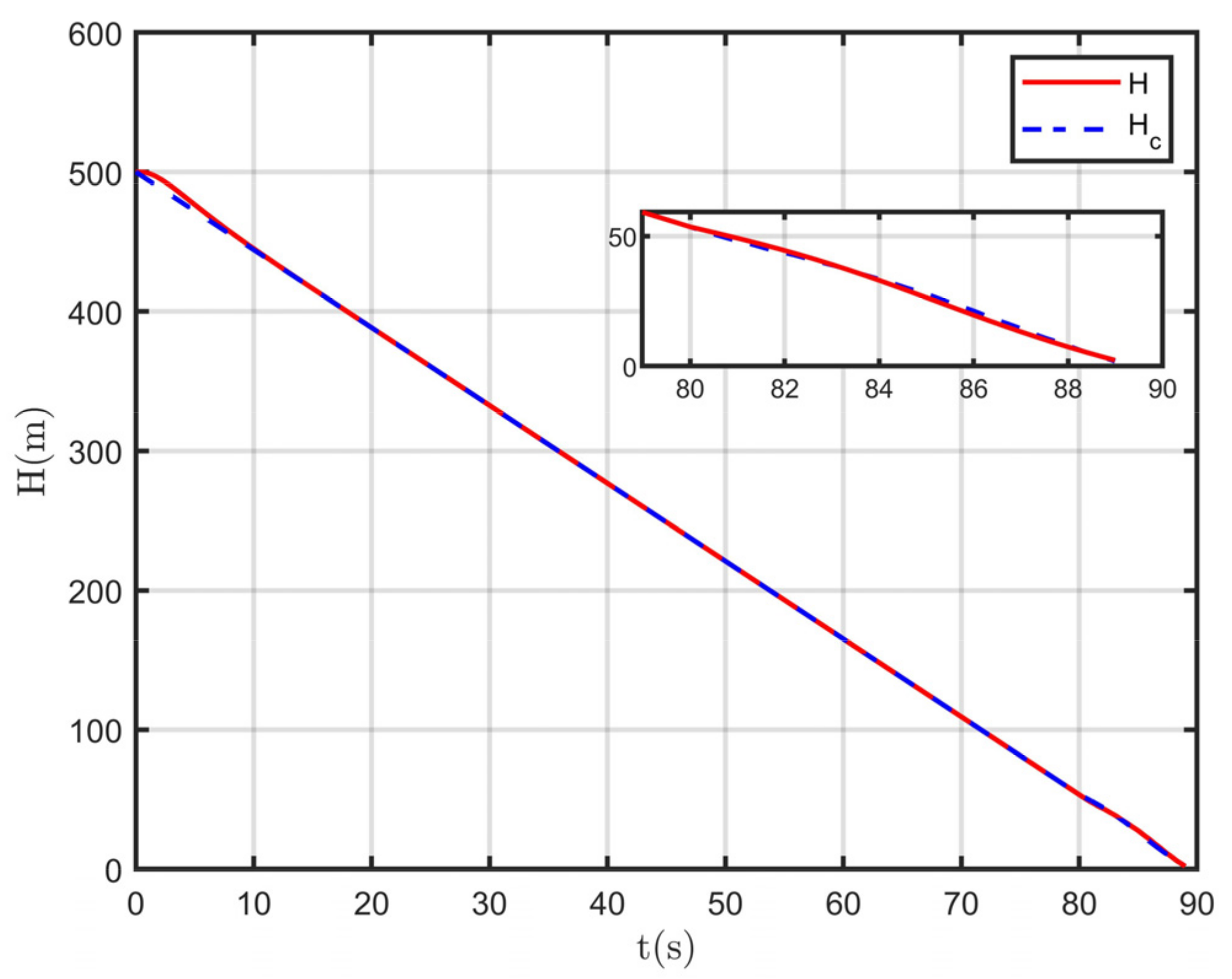
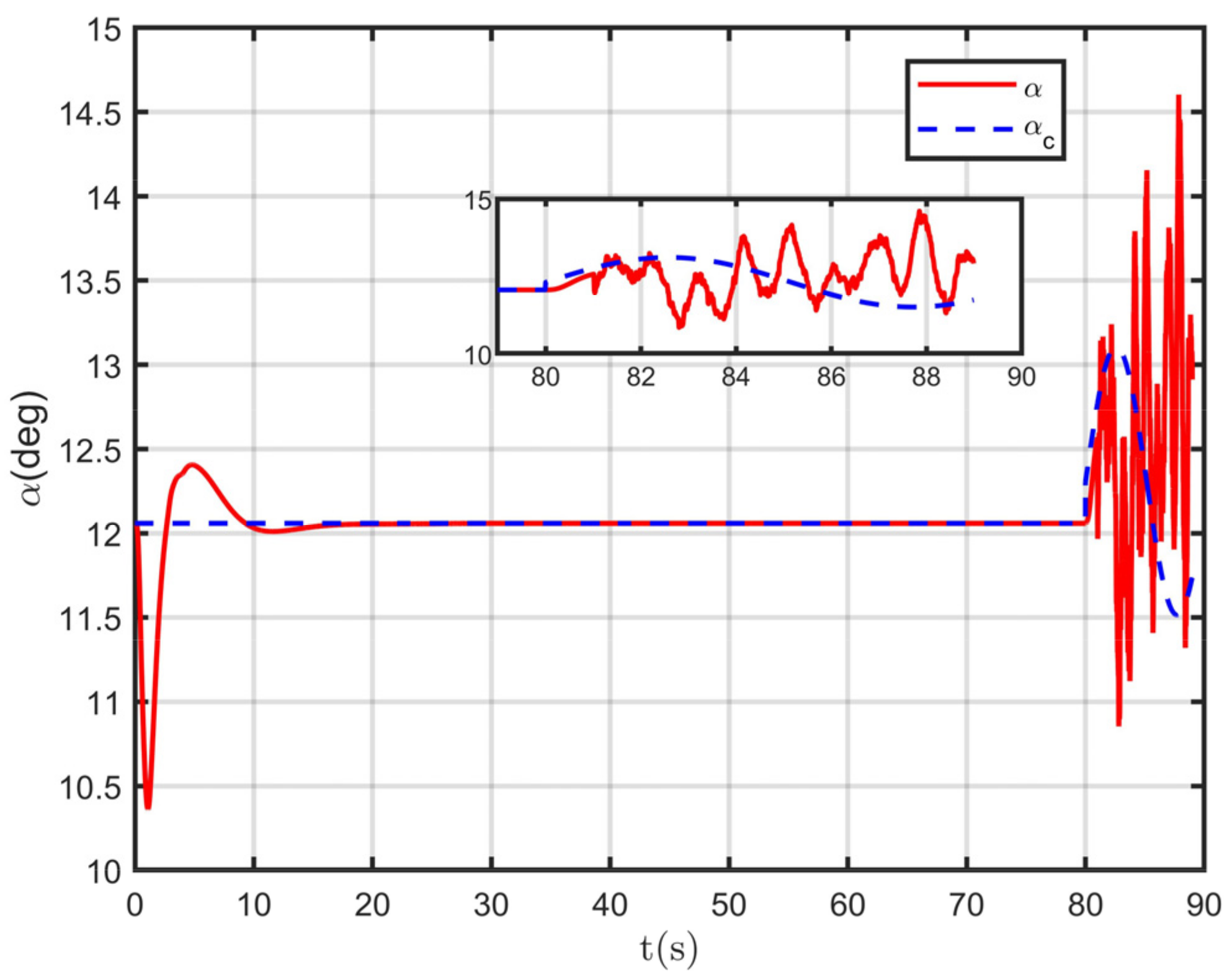
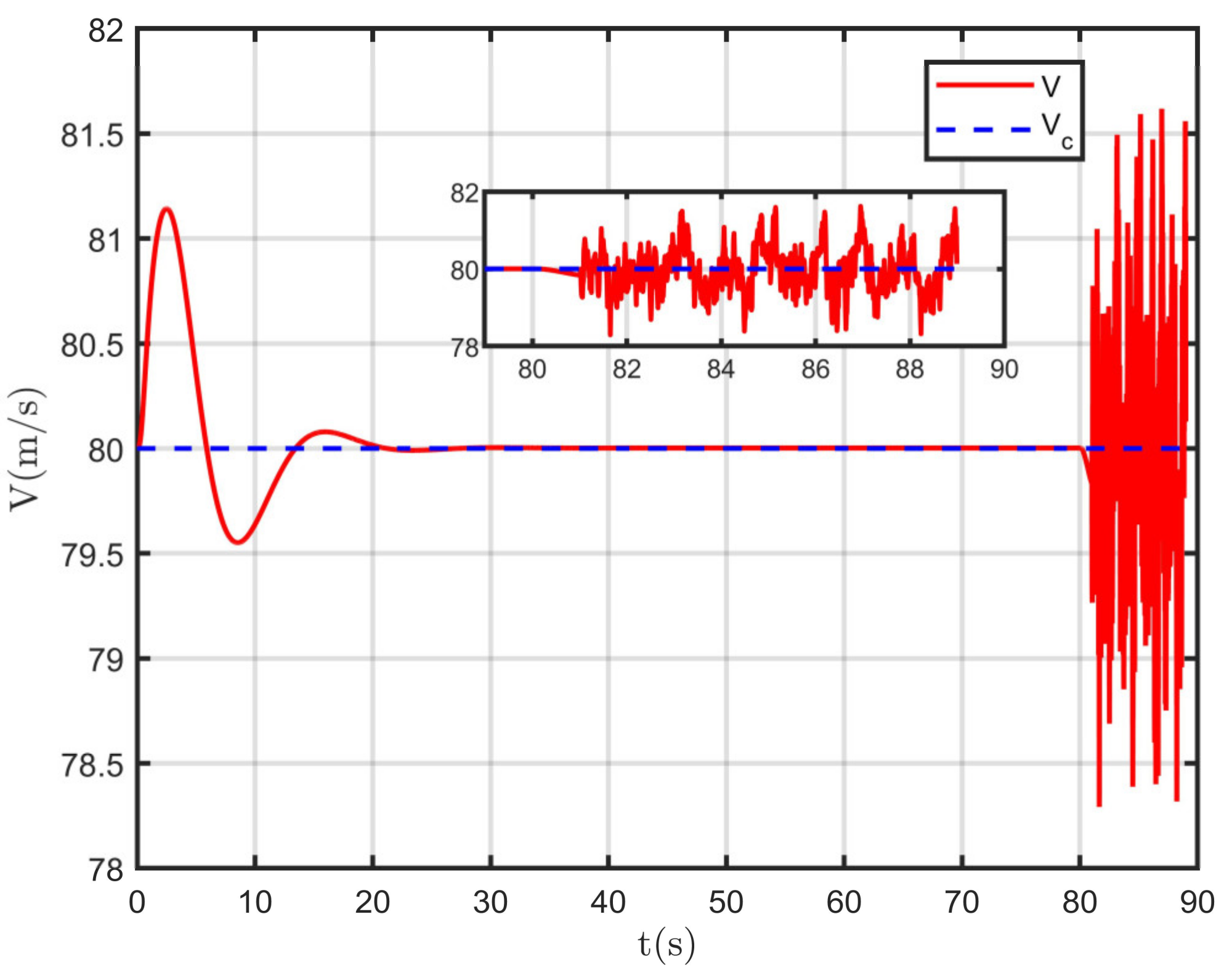
Table 2, simulations of landing control of carrier-based UAVs based on direct lift are carried out. Carrier-based UAV landing control simulations are shown in
Figure 10,
Figure 11,
Figure 12 and
Figure 13.
As can be seen from the response curves of the above loops, in the time of the 80 s, the carrier-based UAV began to glide from a flat turn to approach the UAV carrier, and the flight trajectory angular rate began to change. In order to achieve the trajectory angle required for flight, the height angular velocity curve of attack was tracked quickly and with high accuracy. After the 80 s, the carrier-based UAV deck motion and the air wake interference were introduced, and the flight states fluctuated within a reasonable range and met the design requirements.
6.2. Comparative Simulations
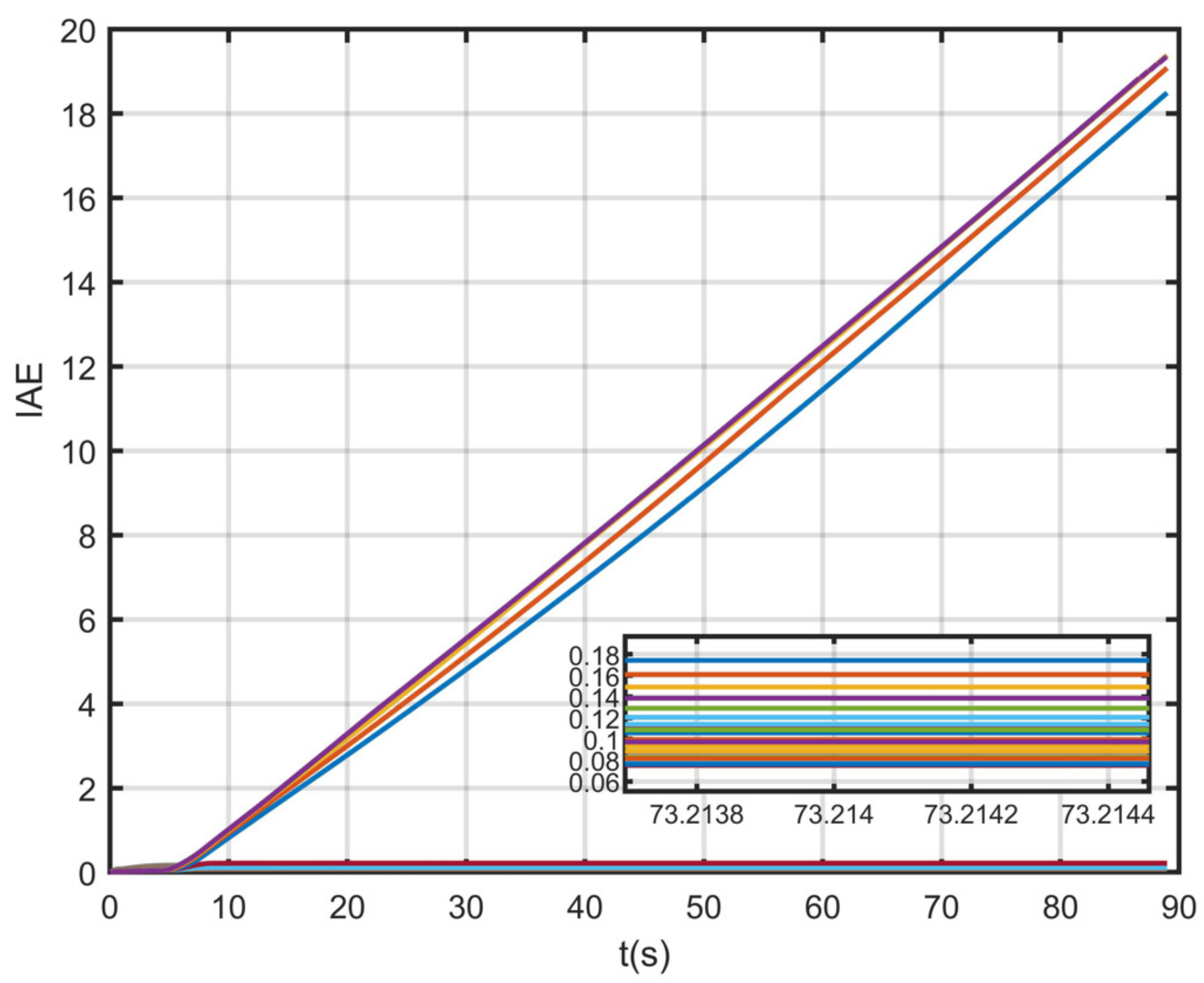
The simulation results of direct lift control gain optimization based on IAE performance index are shown in
Figure 14.
As shown in the process in
Figure 14,
control gain was selected, and the
value was introduced into the landing based on direct lift control structure of the simulation. Each process will produce an IAE curve simulation. In these IAE curves, the IAE value keeps increasing with the integration of time, and the IAE curve keeps rising. When the IAE curve becomes flat with the increase in time, it is proved that the landing control based on direct lift tends to be stable. Bad control gain will lead to an IAE index divergence, and for stable control gain, the control gain
corresponding to the smallest IAE index is the optimized direct lift based landing control gain. Finally, this optimized gain is brought into the landing controller to realize the optimized control because the order of magnitude difference between the trajectory angular rate and lift is large; so, when the gain is designed, the order of magnitude of the gain is given priority. Then, the control gain is multiplied by its order of magnitude to obtain the gain of the controller. This study of magnitude uses
as orders of magnitude.
said in front of the order of magnitude of gain, and direct lift control gain optimization results form based on the performance index, as shown in
Table 3.
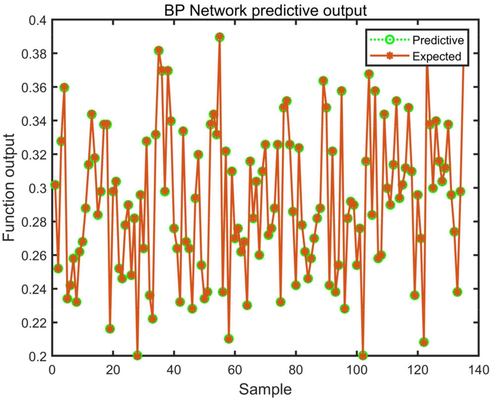
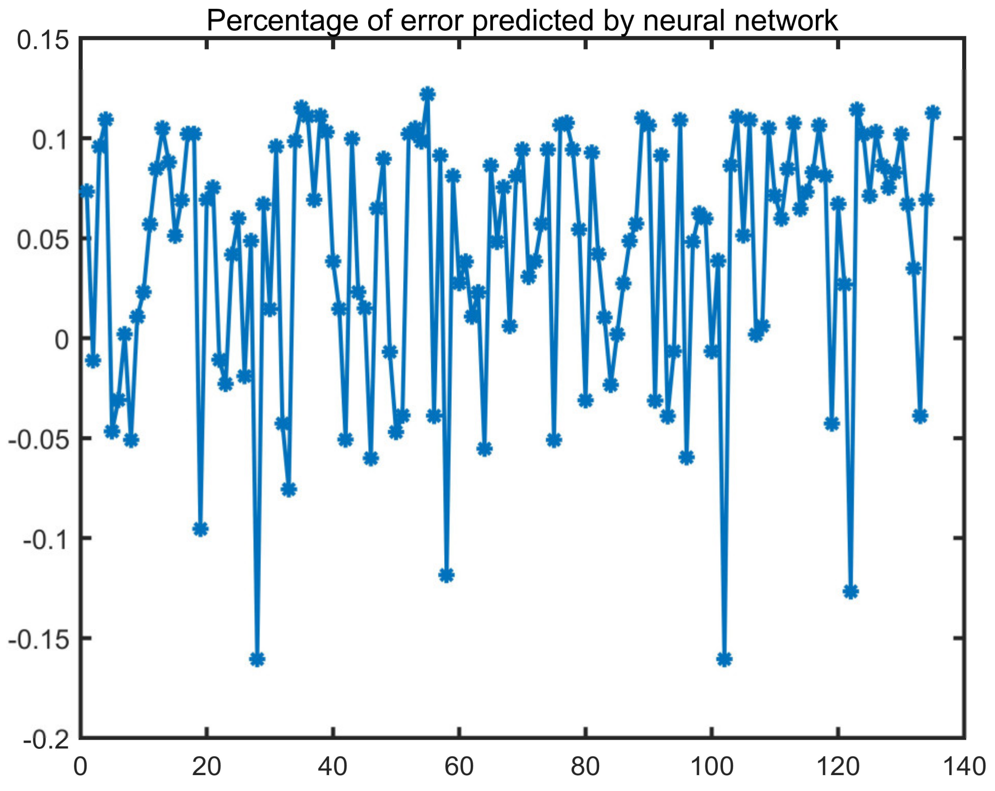
According to the above research content, it is necessary to establish the neural network fitting model with the given off-line pull degrees and the corresponding optimal control gain. The corresponding data obtained through a large number of simulations are brought into the neural network fitting model. In the training and testing of the gain-optimized learning network, there are 1331 sets of data, 90% of which are taken as training and 10% as testing. The test process results are shown in
Figure 15 and
Figure 16.
It can be seen from
Figure 15 and
Figure 16 that the training and testing accuracy of the gain optimized learning network is relatively high, and the relative error is no more than 0.4%.
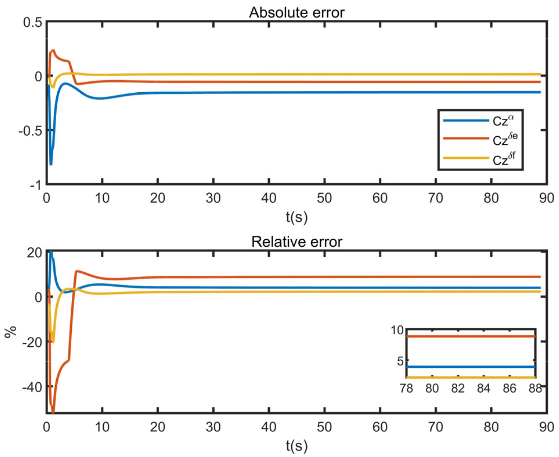
Online application of the gain optimization learning network requires online identification results in the time domain. In order to verify the accuracy of the identification algorithm, simulations are conducted, as shown in
Figure 17 and
Figure 18.
It can be seen in
Figure 17 and
Figure 18 that the recursive least-squares identification algorithm based on the time domain has a high accuracy. In
Figure 18, the red line is the elevator derivative, the blue line is the angle-of-attack derivative and the yellow line is the flap derivative. The relative errors of identification are all within 10%, indicating a high identification accuracy.
Through the gain optimization of direct lift control gain, the optimized gain is brought into the carrier-based landing controller based on direct lift and compared with the unoptimized controller. The results are below.
As can be seen from
Figure 19, after the control gain optimization based on performance indexes, the quality of direct lift control is significantly improved, and the overshoot is reduced by 69.8%, which is conducive to a successful landing.
In the first 60 s of the landing glide, the altitude subsidence rate was reduced from 5.6 m/s to 3.5 m/s, and comparative simulation was conducted for control distribution of the landing glide, in which the distribution algorithm selected a conventional quadratic programming method and dynamic allocation method based on quadratic programming. For the selection of parameters of the allocation algorithm, the weighting
and weighting coefficient matrices
and
of the conventional quadratic programming method and the dynamic allocation method based on quadratic programming took the same parameters, where
,
and
; the extraction matrix
and
in the dynamic allocation algorithm based on quadratic programming contain each rudder surface focus coefficient
, where
is taken as one;
,
and
are normalized according to the deflection rate of each rudder surface, reference F-18 HARV rudder surface deflection rate parameters; the deflection rate limits of
,
and
are, respectively, 20 deg/s, 80 deg/s and 100 deg/s; and the
,
and
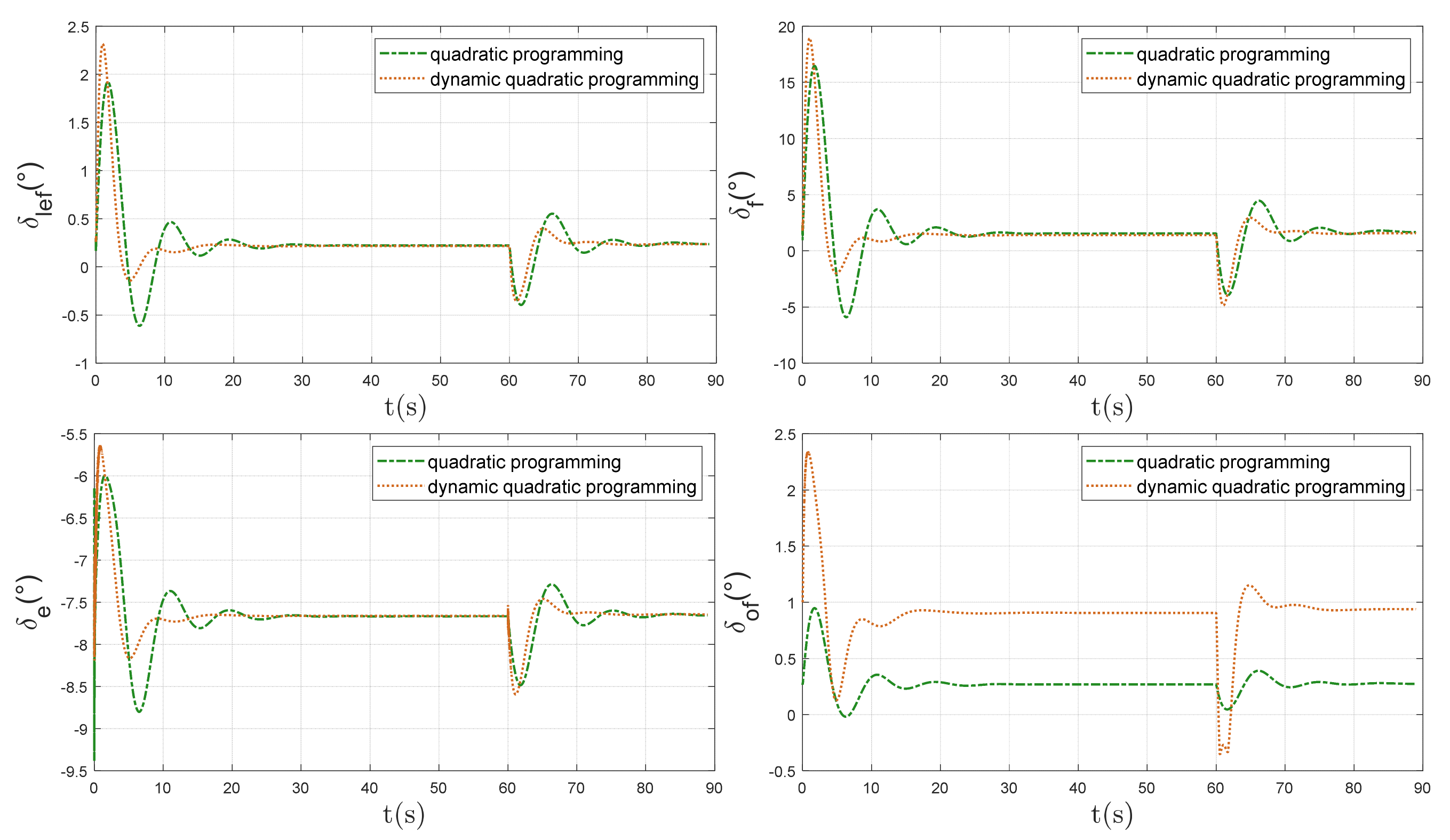
take 1/2, 2/5 and 1/10, respectively. The closed-loop comparison simulation results of landing control allocation are shown in
Figure 20 and
Figure 21.
From the above simulation results, we know that the dynamic control allocation method based on quadratic programming can make the rudder surface allocation results converge faster after the slide trajectory changes, thus making the trajectory angular rate and angle of attack of the angular loop, as well as the speed and altitude of the trajectory loop, converge faster and track up to the target value.
Dynamic coefficient reflects the direct lift instructions. Before 3 s,
is greater than 0.5, focusing on the dynamic allocation algorithm reducing the allocation amount flat tail, as seen from the rudder surface allocation curve in the time flat tail deflection under the dynamic allocation algorithm being decreased in
Figure 21. The dynamic quadratic planning allocation algorithm, which takes into account the landing task and rudder efficiency, reduces the maneuvering surface deflection response time by 10%, compared to the conventional optimization algorithm with fixed weights. The dynamic allocation algorithm increases the deflection angle by more than a factor of two compared to the conventional algorithm because the rudder efficiency of the outer leading edge flaps is set to be the smallest; after the 60 s sink rate of the UAV is reduced, the dynamic coefficients show a short decrease, the allocation algorithm tends to reduce the direct lift-related flap deflection and the outer leading edge flaps have the smallest rudder efficiency, so their deflection is reduced by a factor of four and reverse deflection occurs.
6.3. Monte-Carlo-Based Robust Evaluation
In the process of control gain optimization, excessive gain may lead to controller divergence, so it is necessary to limit the upper and lower limits of landing control gain to prevent the slow process of controller divergence optimization due to excessive control gain. Here, the proportional control gain limit of direct lift is set as the upper limit of 20 and the lower limit of 0.
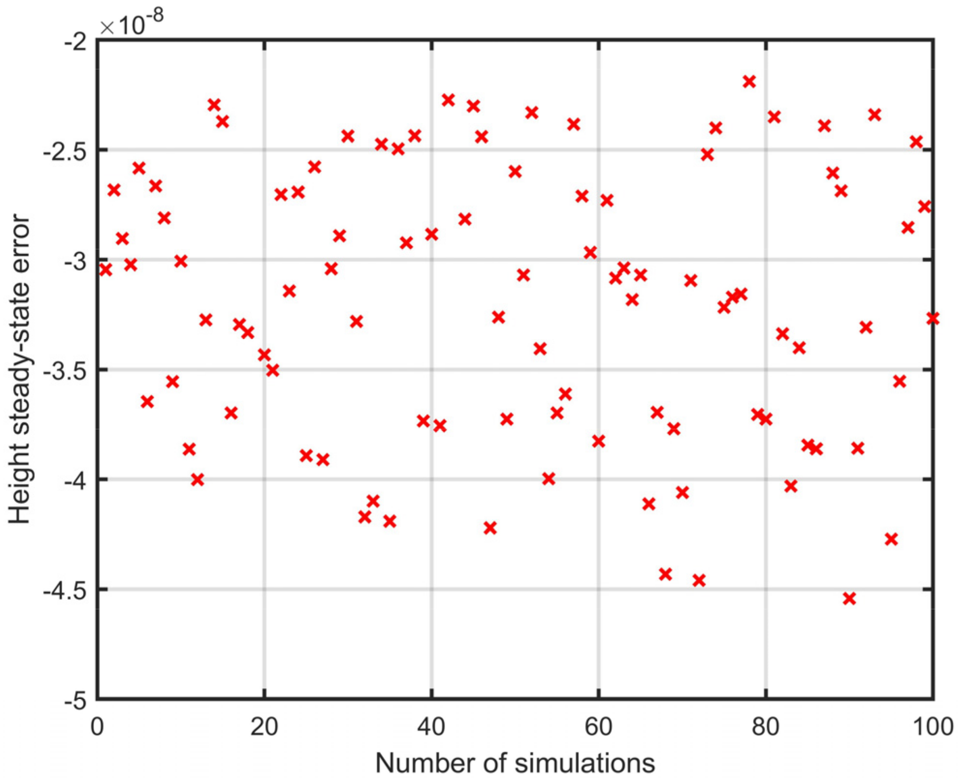
The gain optimized by the gain optimization method based on performance index also needs to be brought into the simulation model for a large number of Monte Carlo pull deviation simulations to evaluate its robustness. Therefore, this paper brings the optimized control gain into the original controller and carries out a large number of Monte Carlo pull deviation simulations. The pull deviation condition was set as Monte Carlo random pull deviation with lift, static stability coefficient and rudder efficiency coefficient all being ±20%. The Monte Carlo simulations of steady-state error/maximum error of landing control height based on direct lift are shown in
Figure 22 and
Figure 23.
It can be seen from
Figure 22 and
Figure 23 that the longitudinal steady-state error is very small, and the maximum error reflects the overshoot of the trajectory tracking. The maximum error is about six, the error is stable in one area and the error distribution is concentrated.

