Article

Designing Ultrahigh Frequency Motor Rotor Position Search Coils for Electric Propulsion in Drones

School of Electrical Engineering, Tiangong University, Tianjin 300387, China
*
Author to whom correspondence should be addressed.
Drones 2023, 7(3), 181; https://doi.org/10.3390/drones7030181
Submission received: 16 January 2023 / Revised: 27 February 2023 / Accepted: 27 February 2023 / Published: 7 March 2023
(This article belongs to the Special Issue Drones: Opportunities and Challenges)

Abstract

:
As the core of electric propulsion in drones, the motor has higher requirements for its reliability and fault tolerance. Accurate acquisition of rotor position information is a prerequisite for a motor-driven drone’s system to operate stably. Traditional search coils can provide fault tolerance for position detection, but they cannot detect rotor position in the full speed range (stationary to rated speed). In order to make the search coils provide rotor position in the full speed range, this study proposes to inject an ultrahigh frequency (UHF) signal (50–100 kHz) into the search coils. By optimizing the self-inductance of the search coil, the mutual inductance between the search coil and the armature winding, the back electromotive force (BEMF) of the search coil, and the mutual inductance between the search coils, the structure of the UHF search coil designed in this paper is helpful to extract the UHF feedback signal. Finally, based on the mapping relationship between the self-inductance of the search coil and the rotor position, the rotor position of the motor can be detected in the full speed range. The novelty of the proposed work lies in the UHF search coil with zero mutual inductance coupling to the armature winding, small BEMF, and low interphase mutual inductance that can detect the rotor position in the full speed domain. Maxwell software is used to optimize the structure of the UHF search coil, and the feasibility of the design results is verified by co-simulation.

1. Introduction

As the motor is the workhorse of the electric propulsion system of drones, which are used in an increasing proportion of civilian and military applications, its reliable operation is crucial [1]. The permanent magnet synchronous motor (PMSM) has been widely used in electric vehicles, drones, and household appliances because of its simple structure, high power density, good reliability, small size, and low moment of inertia [2,3,4]. Real-time and accurate acquisition of rotor position information is important in realizing a stable control system for the PMSM [5]. The traditional position estimation method is obtained by hall element, encoder, and other position sensors, but it is vulnerable to high temperature, dust, and other harsh environments, which will affect the detection accuracy of the position [6,7,8]. Therefore, sensorless control methods of detecting rotor position have been developed rapidly. The most common methods are the back electromotive force (BEMF) method, inductance method, and signal injection method [9,10,11,12]. Although these methods can obtain the rotor position by measuring the stator voltage or current, the technology will be affected by magnetic saturation, cross-coupling, and inverter nonlinearity, resulting in excessive calculation [13,14,15].
Aimed at the disadvantages of rotor position detection using position sensors and sensorless control methods, some scholars proposed to use search coils to detect rotor position [16,17]. The search coil and armature winding are located in the stator slot of the motor. The rotor position is estimated by using the BEMF method, the inductance method, and the signal injection method for the search coil wound in the stator slot to improve the reliability of the motor operation. At the same time, when the position sensor fails, the search coil can also be used as a backup option, which improves the fault-tolerance ability of detecting the rotor position in the drone’s electric propulsion system.
When the PMSM is running at high speed, rotor position can be detected by searching the coil’s BEMF. Based on the mathematical model, estimating the rotor position of a PMSM by using the mutual inductance voltage generated by the search coil in the slot on the armature winding and the BEMF of the search coil was proposed in [18]. A system for monitoring the temperature of the motor and estimating the rotor position was presented in [19]. The principle is that the search coil is connected in series with the thermistor. During operation of the motor, BEMF is generated by the search coil, and the rotor position is obtained by measuring the induced voltage of the thermistor on the search coil. The interior permanent magnet synchronous motor (IPMSM) design for estimating the absolute position of the rotor was proposed in [20]. The proposed motor uses an asymmetric rotor, so that the induced voltage of the search coil is asymmetric with the sector divided by the number of poles, thereby obtaining the absolute position of the rotor. Although this method can obtain the mechanical angle of the rotor, it is necessary to design an asymmetric rotor to divide the position interval, which is not widely applicable.
When the motor is running at low speed, due to the BEMF value being small, the rotor position can be obtained by searching the waveform characteristics of the search coil inductance and injecting the detection signal. It was proposed in [21] that a high-frequency voltage signal should be passed to the search coil, and the rotor position information can then be judged by detecting the induced current in the search coil. However, the induced current gradually decreases with the increase in frequency, which is not easy to detect when the motor is running at high speed. RLC series resonance technology was used to solve the rotor position in [22]: by applying sinusoidal excitation to the resonant circuit, the modulation voltage of the search coil inductance is obtained on the sampling resistor, then the inductance waveform is obtained through the detection circuit, and finally the rotor position is obtained. However, this method is only effective when the motor is stationary. When the armature winding is connected to the current, due to the mutual inductance between the phases, the search coil is greatly impeded, and the position signal is difficult to extract. The active band-pass filter needs to be further introduced, resulting in complex system hardware. On the basis of [22], another method in [23] did not use resonance technology but instead adjusted the parameters of the detection circuit to obtain the rotor position. However, at the same time, in order to reduce the mutual inductance between the armature winding and the search coil phase, this method reduces the maximum value of the self-inductance of the search coil and the sensitivity of rotor position detection.
In summary, the traditional rotor position search coil cannot detect the rotor position of the motor in the full speed range of the motor. When the ultrahigh frequency (UHF) signal is injected into armature windings to detect the rotor position, as in [24], the estimated rotor position is a good way to track the actual position, but this method is only applicable to the IPMSM is in a state of power off or low speed. In order for the rotor position to be provided by the search coil under the full speed domain of the motor, without affecting motor operation, an UHF search coil is proposed in this paper. In this method, the UHF signal is injected into the search coil, and then by reducing the mutual inductance between the search coil and the armature winding, the BEMF of the search coil, and the mutual inductance between the search coils, the structure of the UHF search coil helps to extract the UHF feedback signal. Finally, based on the mapping relationship between the self-inductance of the search coil and the rotor position, and the wide-range detection bandwidth provided by the UHF signal, the rotor position of the IPMSM can be detected in the full speed range.

2. Ultrahigh Frequency (UHF) Search Coils—Rotor Position Detection Principle

2.1. Inductance Change Due to Salient Pole Effect

The actual position of the rotor is included during the operation of a motor whose armature winding self-inductance changes periodically. In the sensorless method, the UHF signal injection into the armature winding is only applicable to the power-off situation or to detect the initial position of the rotor. In order to make it possible to detect the rotor position using the UHF signal injection method, even during the operation of the motor, this paper proposes to detect the rotor position by using search coils.
The IPMSM has the salient pole effect, so the search coil self-inductance is related to the rotor position and varies periodically with rotor rotation. In a motor with three symmetrical distributions of search coils, the self-inductance of each phase is related to the rotor position as the function of
{ L aa = L 0 L 1 cos ( 2 θ ) L bb = L 0 L 1 cos ( 2 θ + 2 π 3 ) L cc = L 0 L 1 cos ( 2 θ 2 π 3 ) M bc = M 0 M 1 cos ( 2 θ ) M ca = M 0 M 1 cos ( 2 θ + 2 π 3 ) M ab = M 0 M 1 cos ( 2 θ 2 π 3 )
where Laa, Lbb, and Lcc are the self-inductance of the three-phase search coil varying with rotor position; Maa, Mbb, and Mcc are the mutual inductance between the search coils; L0 and M0 are the DC components of self-inductance and mutual inductance, respectively; L1 and M1 are the second harmonic amplitudes of self-inductance and mutual inductance, respectively; and θ is the rotor position electrical angle.
Therefore, the correspondence between search coil inductance and rotor position during rotor movement is shown in Figure 1, and the specific rotor position can be determined according to the difference in self-inductance of the three-phase search coil.

2.2. UHF Signal Injection Topology

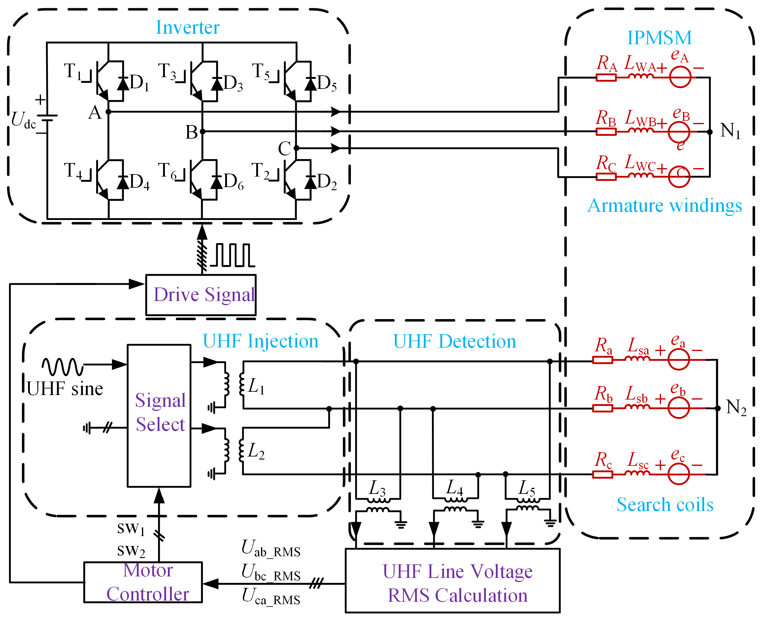
Since the inductance component is not easy to directly observe and detect, this paper proposes to inject the UHF signal alternately into phase “a, b” and phase “b, c” of the search coil. When the rotor rotates, because the self-inductance of the three-phase search coil changes with the rotor position, the root mean square (RMS) of the partial voltage of phase “a” and “b” or phase “b” and “c” inductance also changes with the rotor position in the UHF circuit. By detecting the partial voltage, the rotor position is obtained by comparison and calculation. The motor system topology of the proposed method is shown in Figure 2.
In Figure 2, LWA, LWB, and LWC are the equivalent inductance of the three-phase armature winding, respectively, which includes self-inductance, mutual inductance, and mutual inductance with search coils; eA, eB, and eC are the BEMF of the three-phase armature winding, respectively; Lsa, Lsb, and Lsc are the equivalent inductance of the three-phase search coil, respectively, which includes self-inductance, mutual inductance, and mutual inductance with armature windings; and ea, eb, and ec are the BEMF of the three-phase search coil, respectively.
The DC voltage Udc injects drive current into the armature windings through the inverter and the UHF sinusoidal voltage signal through SW1 and SW2 channel signal selection, which injects respectively into the phase “a, b” or phase “b, c” search coil; the UHF signal injection circuit and the three-phase search coil are connected by the isolation transformers L1 and L2. At the same time, the excitation phase of the search coil and the non-excitation phase UHF line voltage are detected, and the detection circuit and the three-phase search coil are connected by the isolation transformer L3L5. After the RMS of the line voltage is calculated, the rotor position is calculated, and the calculated rotor position signal is transmitted to the motor controller, the obtained drive signal is transmitted to the inverter T1–T6 power device to control the continuous operation of the motor.
In order to obtain a large inductive reactance value to benefit the detection of the partial voltage signal and provide a wide range of detection bandwidth for inductance detection, sinusoidal voltage with a frequency of 100 kHz for the UHF signal was selected. At the same time, in order to reduce the current on the search coil and avoid excessive additional torque, the UHF signal amplitude was selected as 5 V to realize the normal operation of the motor controlled by the driving current of the armature windings and detect the position of the rotor using the UHF search coils.

2.3. Rotor Position Detection Method

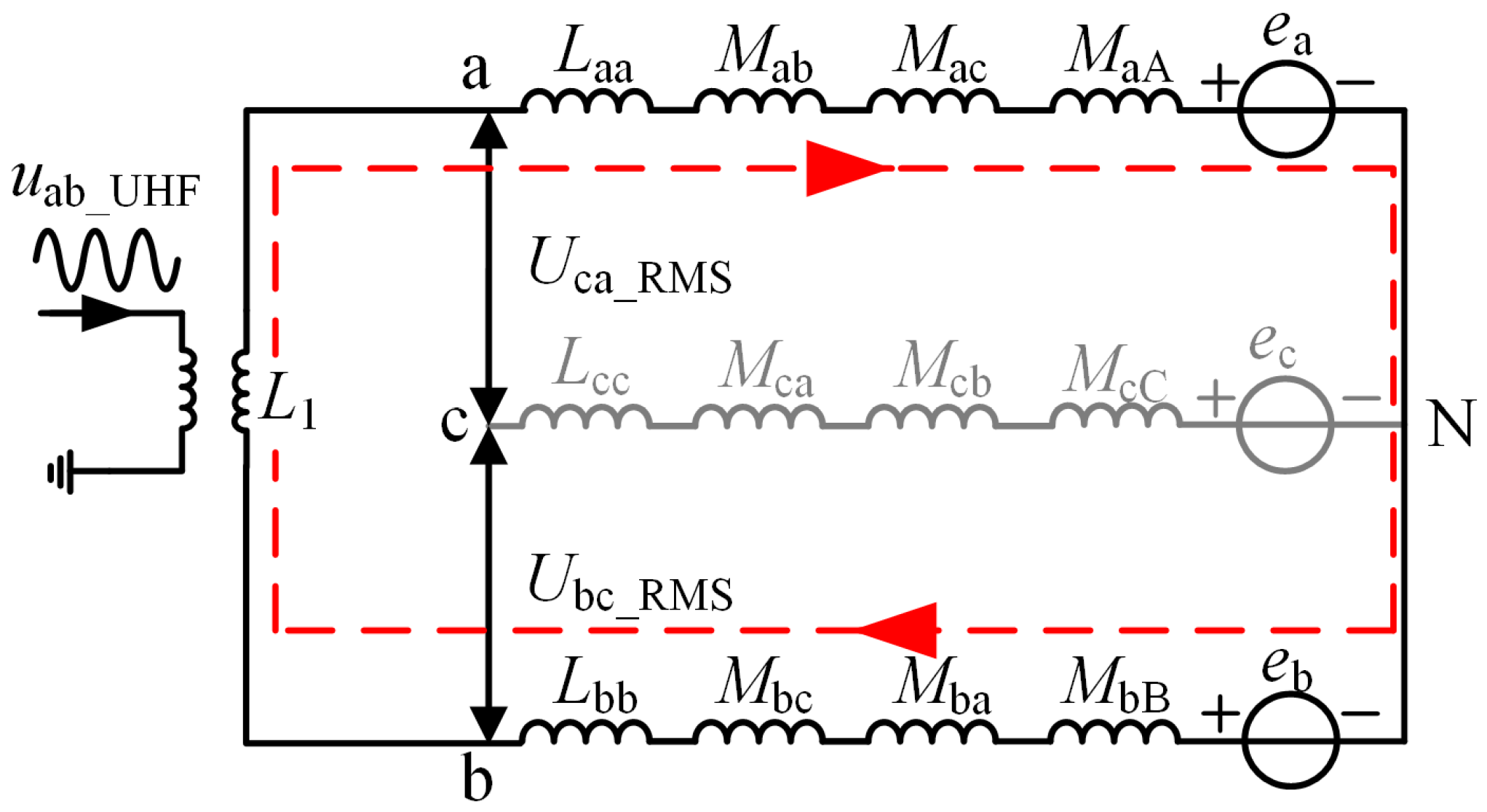
The resistance value of the search coil under the UHF signal is far less than the inductive reactance value, which can be ignored. The armature winding and search coil have the maximum mutual inductance at the same phase, and the three-phase search coil has phase mutual inductance. Therefore, the equivalent circuit of injecting the UHF voltage signal into phase “a, b” of the search coil is shown in Figure 3, where MaA, MbB, and McC are the mutual inductance of the search coil and armature winding in the same phase, respectively.
In Figure 3, Uca_RMS is the RMS of line voltage of the phase “c” and “a” search coil; and Ubc_RMS is the RMS of line voltage of the phase “b” and “c” search coil. Figure 3 above shows that when phase “a, b” search coils are injected, phase “c” is open and no UHF current passes through, Ia = −Ib = IUHF. If the motor is running at this time, the current of the armature winding is IA, IB, and IC, respectively, and ω is motor frequency, then the partial voltage is
{ U ca _ RMS = ( U cN U aN ) | RMS = ω UHF I UHF | ( M ca M cb ) ( L aa M ab ) | + ω ( I C | M cC | I A | M aA | ) + ( e c e a ) | RMS U bc _ RMS = ( U bN U cN ) | RMS = ω UHF I UHF | ( M ba L bb ) ( M ca M cb ) | + ω ( I B | M bB | I C | M cC | ) + ( e b e c ) | RMS
It can be determined from Equation (2) that the line voltage RMS of search coils not only contains the self-inductance voltage of each phase, but it also includes the mutual inductance voltage generated by the search coil due to the armature winding, the mutual inductance voltage between the phases of the search coil, and the line BEMF, resulting in a complex equivalent circuit model, increasing the difficulty of calculation.
Therefore, in order to detect the rotor position during motor operation and simplify the calculation, the ideal search coil should meet the following conditions: (1) the peak value of the self-inductance of the search coil is large to benefit signal detection and reflect the rotor position sensitively; (2) the mutual inductance coupling between the search coil and the armature winding is small to reduce the mutual influence between the high-frequency signals of the search coil and the low-frequency signals of the armature winding; (3) the BEMF of the three-phase search coil is small, so it is easy to extract the UHF feedback signal; and (4) the search coil phase mutual inductance is small, the open side potential is approximately equal to the neutral potential, and line voltage is approximately equal to phase voltage.
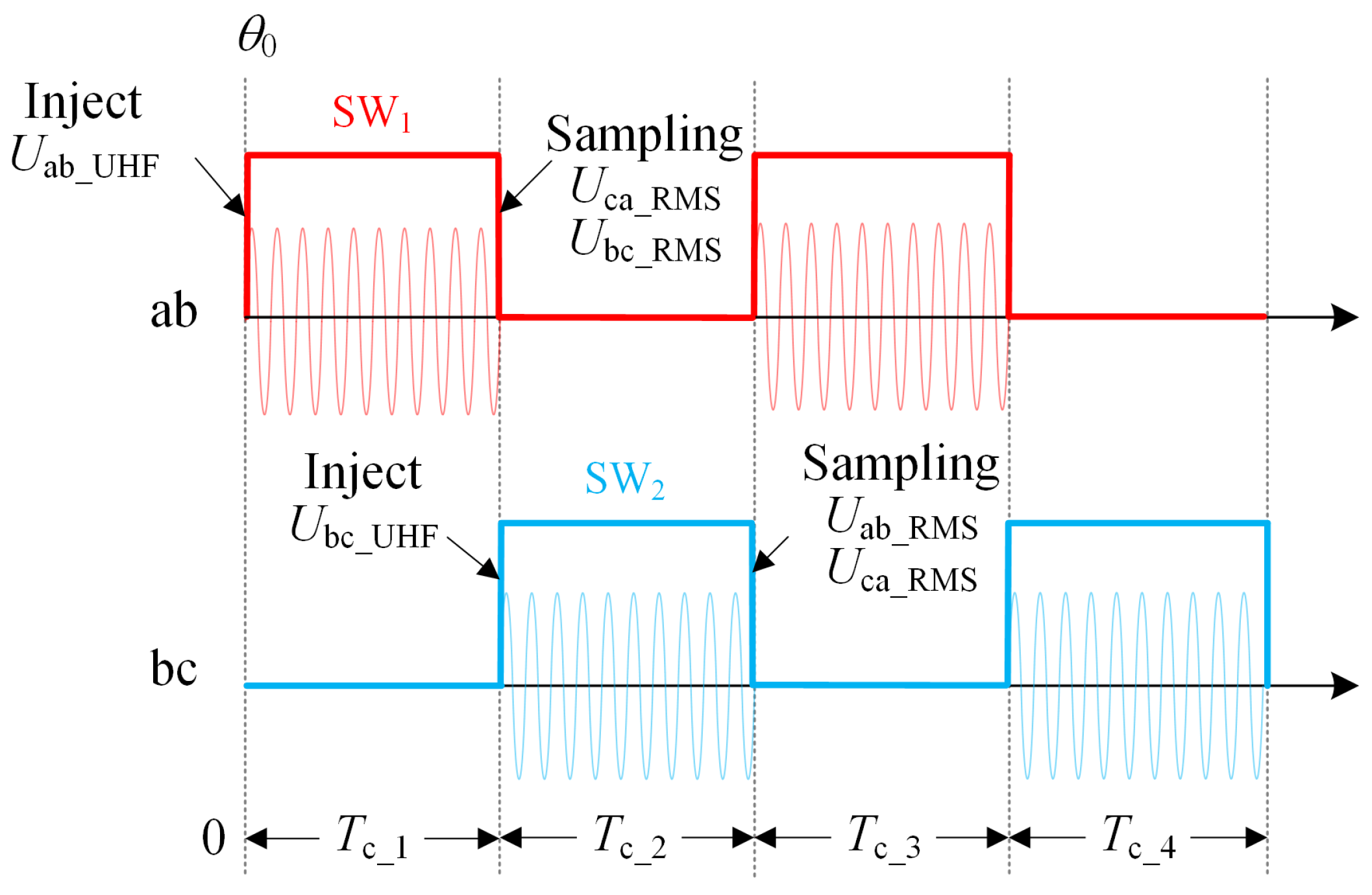
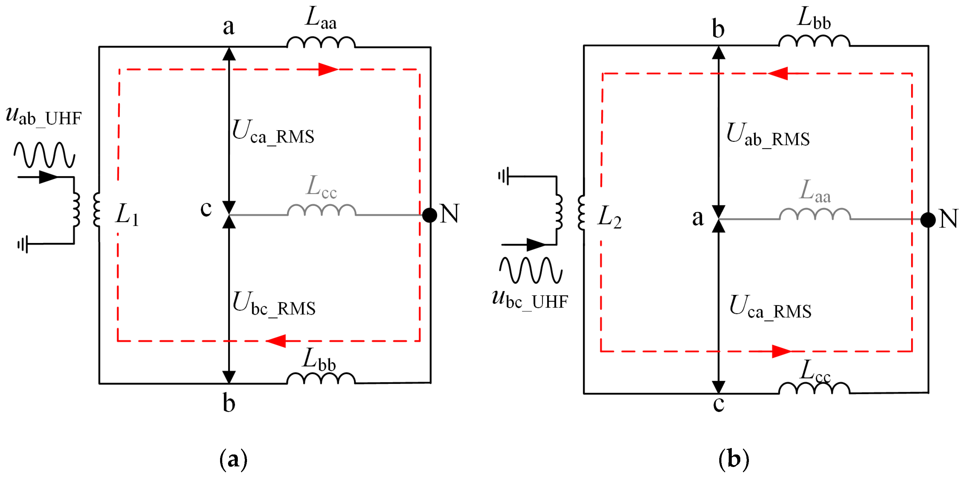
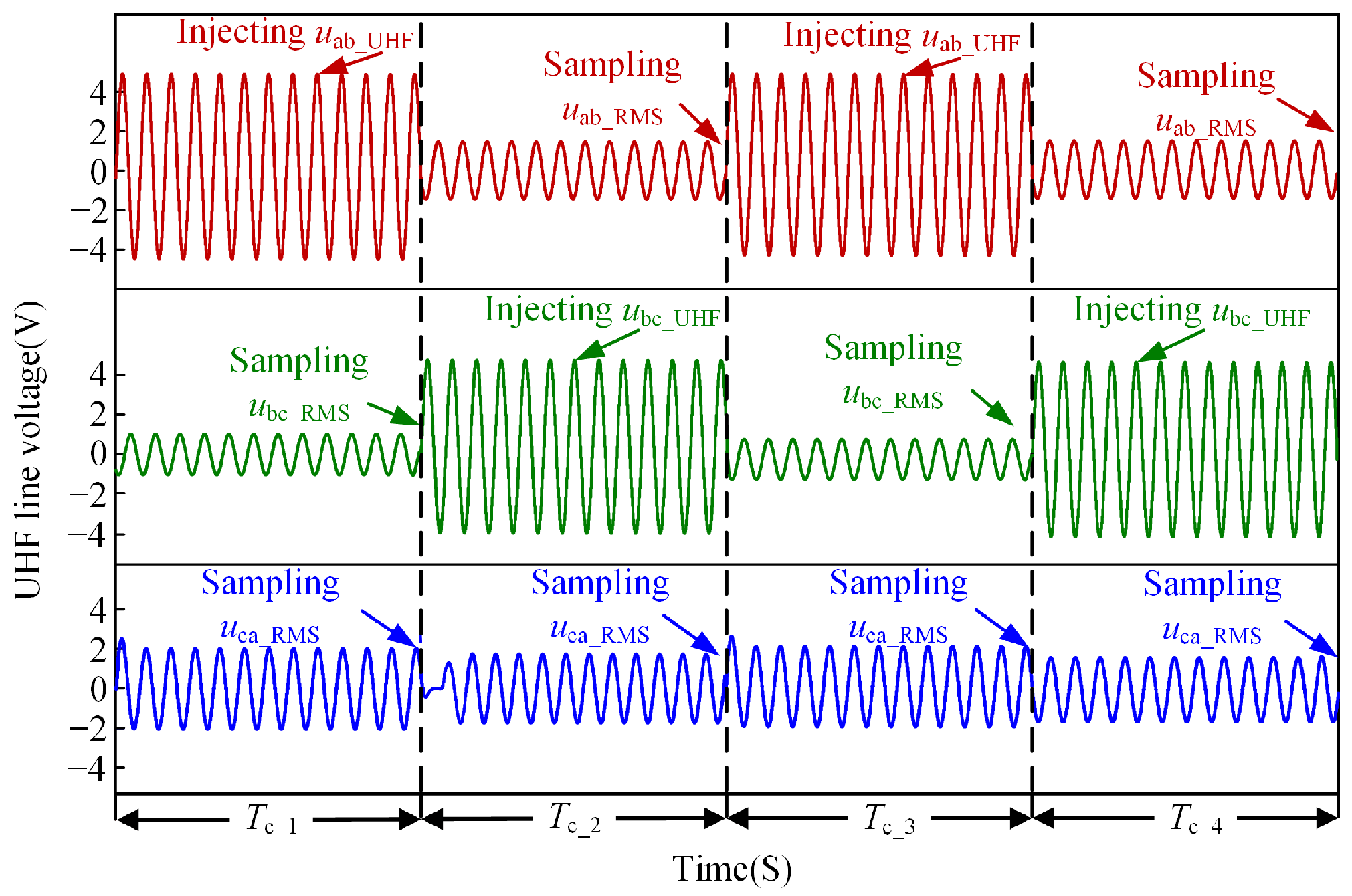
If the search coil meets the above ideal conditions, the initial position θ0 of the rotor is determined by the method of forced positioning of a specific vector through the inverter, as shown in Figure 4. From 0 s, the UHF sinusoidal voltage is output by sequentially selecting the SW1 and SW2 channels, and the UHF sinusoidal voltage signal is injected into phases “a, b”, “b, c”, and “a, b” in turn during control periods Tc_1, Tc_2, and Tc_3. Because the UHF voltage signal is injected into different phases during every interval of a control period, Tc, Tc_2, and Tc_1 have a control period difference in the acquisition time. At this time, the rotor position has been updated to Δθ. If the rotor position at the last time of Tc_2 is θ, then the rotor position at the last time of Tc_1 is (θ Δθ). The equivalent circuit of the UHF voltage signal injected into phase “a, b” is shown in Figure 5a. The phase “c” search coil is open, and no UHF current passes through.
So, the partial voltage of the two search coils can be calculated as
{ U ca _ RMS = U aN _ RMS ( θ Δ θ ) = ω UHF I UHF ( θ Δ θ ) L aa ( θ Δ θ ) U bc _ RMS = U bN _ RMS ( θ Δ θ ) = ω UHF I UHF ( θ Δ θ ) L bb ( θ Δ θ )
The ratio of the two voltages is calculated in Equation (3), that is,
k 1 = U ca _ RMS ( θ Δ θ ) U bc _ RMS ( θ Δ θ ) = L aa ( θ Δ θ ) L bb ( θ Δ θ )
Therefore, the RMS of line voltage of phase “c” and “a” and the RMS of line voltage of phase “b” and “c” reflect the relationship between Laa and Lbb.
Similarly, the UHF signal is injected into phase “b, c”, the equivalent circuit when the phase “a” search coil is open, as shown in Figure 5b. At this time, the partial voltage of the two search coils can be calculated as
{ U ab _ RMS = U bN _ RMS ( θ ) = ω UHF I UHF ( θ ) L bb ( θ ) U ca _ RMS = U cN _ RMS ( θ ) = ω UHF I UHF ( θ ) L cc ( θ )
The ratio of the two voltages is calculated in Equation (5), that is,
k 2 = U ab _ RMS ( θ ) U ca _ RMS ( θ ) = L bb ( θ ) L cc ( θ )
Therefore, the RMS of line voltage of phase “a” and “b” and the RMS of line voltage of phase “c” and “a” reflect the relationship between Lbb and Lcc.
Since Δθ takes a small value in a control period, in the process of obtaining the self-inductance ratio, Taylor series expansion is carried out for cos(2Δθ) and sin(2Δθ), and the second order truncation error is taken, that is
{ Δ θ = ω T c cos ( 2 Δ θ ) 1 sin ( 2 Δ θ ) 2 Δ θ
Combining Equations (4), (6) and (7), the relationship between rotor position and the ratio of inductance k1 and k2 at this moment is
θ T c _ 2 = 1 2 arctan [ ( k 2 1 ) ( 3 2 3 k 1 Δ θ ) Δ θ ( 2 k 1 4 k 2 2 k 1 k 2 + 4 ) + 3 ( k 2 2 k 1 k 2 + 1 ) ] + μ π 2 ( μ = 0 , 1 , 2 , 3 )
Since the range of the arctangent angle is [−π/2, π/2], and the range of the motor rotor position θ is [0, 2π]. Equation (8) will have four different solutions, so the angle solution that closest to the initial position θ0 is the rotor position θ.
The UHF signal is injected into phase “a, b” in control period Tc_3, and at the last time of Tc_3, the rotor position is updated to θ, and k1 and k2 values are updated to
{ k 2 = U ab _ RMS ( θ Δ θ ) U ca _ RMS ( θ Δ θ ) = L bb ( θ Δ θ ) L cc ( θ Δ θ ) k 1 = U ca _ RMS ( θ ) U bc _ RMS ( θ ) = L aa ( θ ) L bb ( θ )
The relationship between rotor position and the ratio of inductance at this moment is
θ T c _ 3 = 1 2 arctan [ 3 ( k 2 1 ) 2 3 ( k 1 1 ) ( k 2 + 1 ) Δ θ 2 Δ θ ( k 2 1 ) ( k 1 1 ) + 3 ( k 2 2 k 1 k 2 + 1 ) ] + μ π 2 ( μ = 0 , 1 , 2 , 3 )
Similarly, the above Equation (10) has four different solutions, where the result closest to θTc_2 solved in the previous control period is the final result.
The UHF sinusoidal voltage is injected into phase “a, b” and phase “b, c” in turn, to update the rotor position in each subsequent control period by analogy.

3. Search Coils—Design and Optimization

3.1. Search Coils—Design

The requirements of the ideal search coil that can simplify the calculation are analyzed in the previous section. Therefore, this section proposes an optimal design method for the search coil. By changing the search coils’ internal connection structure, the mutual inductance with the armature winding, the mutual inductance between the phases, and the BEMF can all be reduced, thereby simplifying the UHF signal injection into the search coil equivalent circuit model and facilitating the calculation of the motor rotor position in the drone’s electric propulsion system.
The placement of the search coils is shown in Figure 6. The search coil axis is aligned with the three-phase axis of the armature winding to make the inductance change rule consistent with the armature winding inductance change rule, and the actual position information of the rotor can be directly obtained by using the search coil.
In order for the motor to have a higher power density in the drone’s electric propulsion system, in this paper, a 48-slot 8-pole IPMSM is taken as an example for analysis. Figure 7 is a simplified schematic diagram of the motor structure with search coils. The armature winding is located on the inner side of the stator slot, the number of parallel branches of each phase is four, and the star connection is adopted. The search coil is located outside the stator slot, and each phase is connected in series with four coils under the same magnetic pole. The number of parallel branches is one, and the star connection is adopted. The neutral point of the search coil and the neutral point of the armature winding exist independently.

3.2. The Search Coils and Armature Winding—Mutual Inductance Optimization

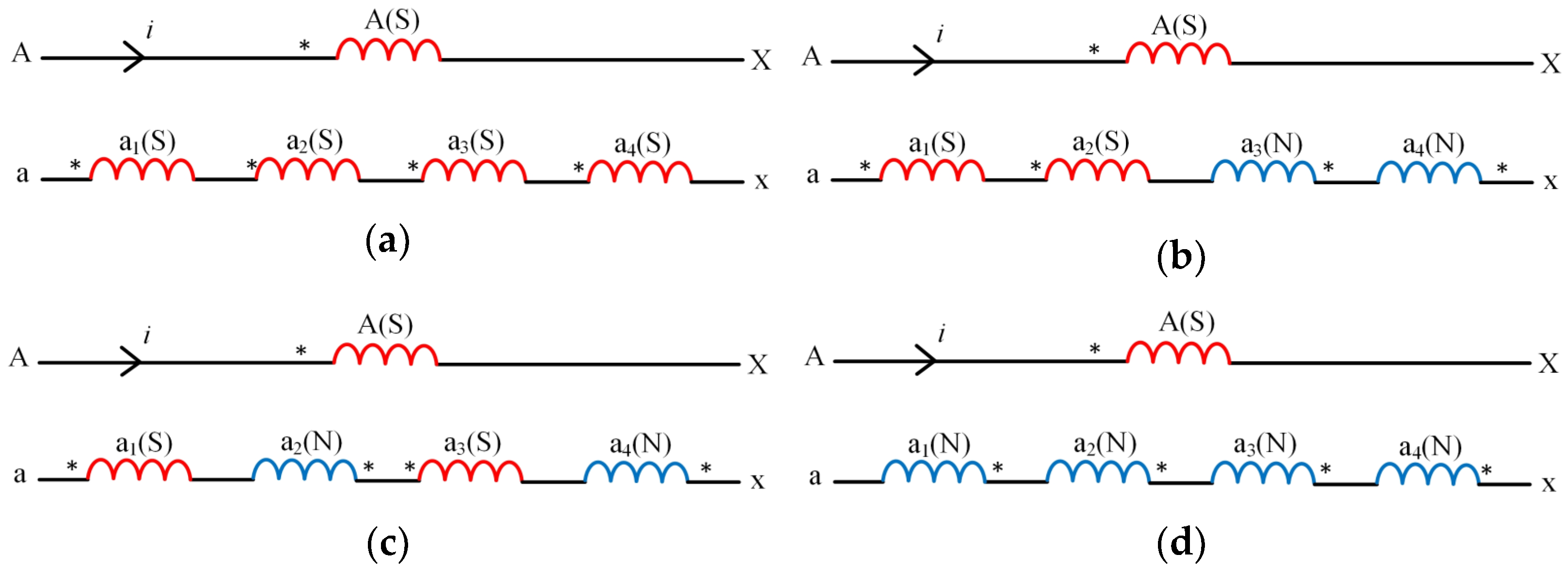
The premise that the search coil can be independent of the armature winding is that the coupling relationship is small, that is, the induction voltage generated by the search coil due to the armature winding is zero. Taking phase “a” as an example, the influence of search coil connection structure on mutual inductance is analyzed. Figure 8 is a schematic diagram of search coils with different connection structures. “A–X” represents a-phase armature winding, and “a–x” represents an a-phase search coil, which is composed of four coils, a1–a4, arranged in counterclockwise order in series inside the motor. “*” indicates the dotted terminal direction of the armature winding and the search coil; if the armature winding and search coil dotted terminals are on the same side, this is recorded as “S”, and if they are not, it is recorded as “N”. Therefore, according to the different dotted terminal positions, a phase search coil can include four structures, including “SSSS”, “SSNN”, “SNSN”, and “NNNN”.
The arrow indicates the current direction of the A-phase armature winding in Figure 8a. According to the incoming current, the induced voltage of the four coils of the SSSS structure is
u Aa 1 = u Aa 2 = u Aa 3 = u Aa 4 = M d i d t
where M is the mutual inductance coefficient between the armature winding and the search coil, and uAa1, uAa2, uAa3, and uAa4 are the induced voltages generated by a1–a4, respectively, so the induced voltage of the phase-a search coil is
u Aa = u Aa 1 + u Aa 2 + u Aa 3 + u Aa 4 = 4 M d i d t
Therefore, depending on the connection structure, the induced voltage can be denoted as Equation (13).
u Aa = i = 1 4 ( 1 ) a M d i d t
When the dotted terminals are on the same side, a = 2; when the dotted terminal is on a different side, a = 1. Therefore, the relation of absolute value of the mutual inductance coefficient between search coils of different structures and the armature winding is
| M Aa | SSSS = | M Aa | NNNN > | M Aa | SSNN = | M Aa | SNSN = 0
So, the SSNN and SNSN structure on the search coil induction electromotive force can offset each other, and result in the minimum coupling relationship between the armature winding and search coil. The amplitude of induced electromotive force on SSSS-structure and NNNN-structure search coils is the maximum value, which is not conducive to the decoupling of the two signals. It can be concluded that in order to obtain the minimum induced electromotive force, the search coil structure should have two “S” and two “N” coils, so the search coil structure can be selected as the SSNN structure or SNSN structure.
Search coils with the two “S” and two “N” structure can also simultaneously cancel the opposite electromotive forces of each phase. Taking the a-phase search coil as an example, the SSNN structure and SSSS structure are analyzed and compared. If the BEMF of each “S” coil is positive, and the BEMF of the “N” coil is negative, the above eight kinds of BEMF are
{ e 1 a 1 = e 1 a 2 = e 1 a 3 = e 1 a 4 = 2 E cos ( ω t ) e 2 a 1 = e 2 a 2 = e 2 a 3 = e 2 a 4 = 2 E cos ( ω t )
where e1a1, e1a2, e1a3, and e1a4 are the fundamental wave BEMF generated by coils a1, a2, a3, and a4 in the magnetic field of the SSNN structure; and e2a1, e2a2, e2a3, and e2a4 are the fundamental wave BEMF generated by coils a1, a2, a3, and a4 in the magnetic field of the SSSS structure, respectively. E is the effective value of fundamental BEMF generated by the magnetic field on coils a1, a2, a3, and a4.
As can be seen from Figure 8, the a-phase search coil is composed of coils a1, a2, a3, and a4 in series. Therefore, the BEMF e1a and e2a of the a-phase search coil with the structures of SSNN and SSSS are
{ e 1 a = e 1 a 1 + e 1 a 2 + e 1 a 3 + e 1 a 4 = 0 e 2 a = e 2 a 1 + e 2 a 2 + e 2 a 3 + e 2 a 4 = 4 2 E cos ( ω t )
The algebraic sum of the electromotive force of the a-phase search coil in the SSNN structure is zero, and the algebraic sum of the electromotive force of the a-phase search coil in the SSSS structure is the largest, according to Equation (16). Therefore, choosing a search coil with the two “S” and two “N” structure can not only eliminate the mutual inductance coupling with the armature winding but can also cancel electromotive force, which is helpful to extract the UHF feedback signal.

3.3. The Search Coils—Mutual Inductance Optimization

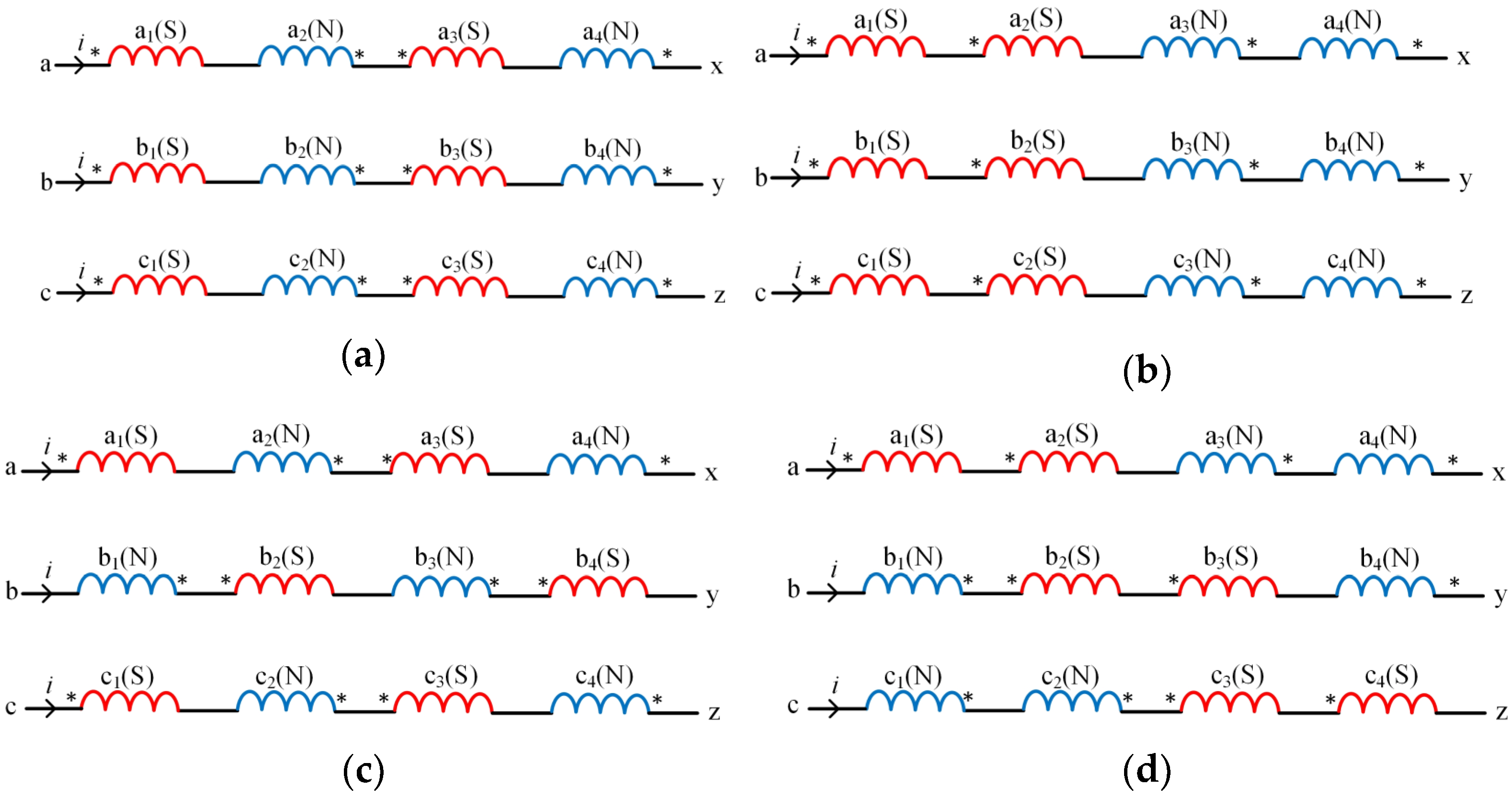
According to the above analysis, the UHF voltage is extracted from the three-phase search coil, and the potential of the non-excited phase is equal to the potential of the neutral point of the search coil under ideal conditions. Therefore, the mutual inductance voltage generated by the non-excited phase relative to the excited phase should be zero, that is, the phase mutual inductance coupling of the three-phase search coil is minimal. The number of turns and pitches of coils in the motor are the same, and only the spatial position is different, as shown in Figure 7. Mutual inductance of search coils only decreases with the increase in distance. Therefore, mutual inductance between each phase and its adjacent phase coils (such as Ma1b1, Mb1c1, Mc1a2) only needs to be studied, and the absolute value of mutual inductance is the maximum. Figure 9 are three-phase search coil connection diagrams. The arrows indicate the current direction of the three-phase search coil. In the connection diagram of the SNSN-structure three-phase search coil shown in Figure 9a, each phase enters current respectively, and the three-phase mutual inductance coefficient is
{ M ab = M a 1 b 1 + M a 2 b 2 + M a 3 b 3 + M a 4 b 4 = 4 M M bc = M b 1 c 1 + M b 2 c 2 + M b 3 c 3 + M b 4 c 4 = 4 M M ca = M c 1 a 2 M c 2 a 3 M c 3 a 4 M c 4 a 1 = 4 M
That is, when the a-phase search coil is energized, the absolute values of the induced electromotive force of phases “b” and “c” are both the maximum values. Therefore, this connection structure cannot reduce the mutual inductance of any two phases of search coils.
In the connection diagram of the SSNN-structure three-phase search coil shown in Figure 9b, each phase enters current respectively, and the three-phase mutual inductance coefficient is
{ M ab = M a 1 b 1 + M a 2 b 2 + M a 3 b 3 + M a 4 b 4 = 4 M M bc = M b 1 c 1 + M b 2 c 2 + M b 3 c 3 + M b 4 c 4 = 4 M M ca = M c 1 a 2 M c 2 a 3 + M c 3 a 4 M c 4 a 1 = 0
That is, when the a-phase search coil is energized, the absolute value of induced electromotive force in phase “b” is the largest, and the induced electromotive force in phase “c” can cancel each other out. Therefore, this connection structure can only reduce the mutual inductance of the phase “c” and phase “a” search coils.
The above phase “b” and phase “c” search coil connection structures move 360° and 720° of electrical angle, respectively, to obtain new phase “b” and phase “c” connection structures, namely the structures of SNSN_1 and SSNN_1. As shown in Figure 9c,d, the current is passed into each phase respectively, so the three-phase mutual inductance coefficients of the two structures are, respectively,
{ M ab SNSN _ 1 = M bc SNSN _ 1 = M ca SNSN _ 1 = 4 M M ab SSNN _ 1 = M bc SSNN _ 1 = M ca SSNN _ 1 = 0
For the SNSN_1 structure, when any phase search coil is energized, the absolute values of induced electromotive forces of the other two phases are at the maximum, and the three-phase search coil has the largest phase mutual inductance coupling relationship; for the SSNN_1 structure, when any phase search coil is energized, the other two phases’ induced electromotive forces can cancel each other, which is conducive to reducing the phase mutual inductance coupling of the three-phase search coil. Therefore, the search coil structure was finally selected as the SSNN_1 structure.

4. Simulation Results and Analysis

After obtaining the idealized structure of the search coil, the UHF signal can be injected into the optimized search coil. Firstly, the finite element analysis (FEA) model of the UHF search coil is established. The search coil structure is the optimized SSNN_1 structure, which reduces mutual inductance coupling between the coils. Secondly, the drive circuit model of Simplorer and the control circuit model of Simulink are established according to the UHF injection and detection method. Finally, with the help of Matlab and Ansoft simulation software, the two are combined to verify the feasibility of the proposed method.

4.1. FEA Verification

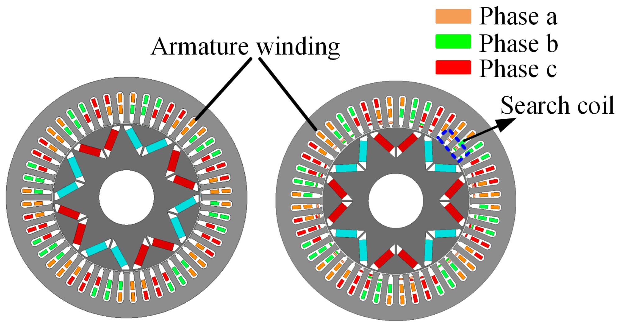
Figure 10 shows the initial FEA motor model and the FEA motor model with the addition of the search coils. The stator slot contains the armature winding and search coil, the number of parallel branches of armature winding is four, and the number of parallel branches of search coils is one. The parameters of the motor are shown in Table 1.
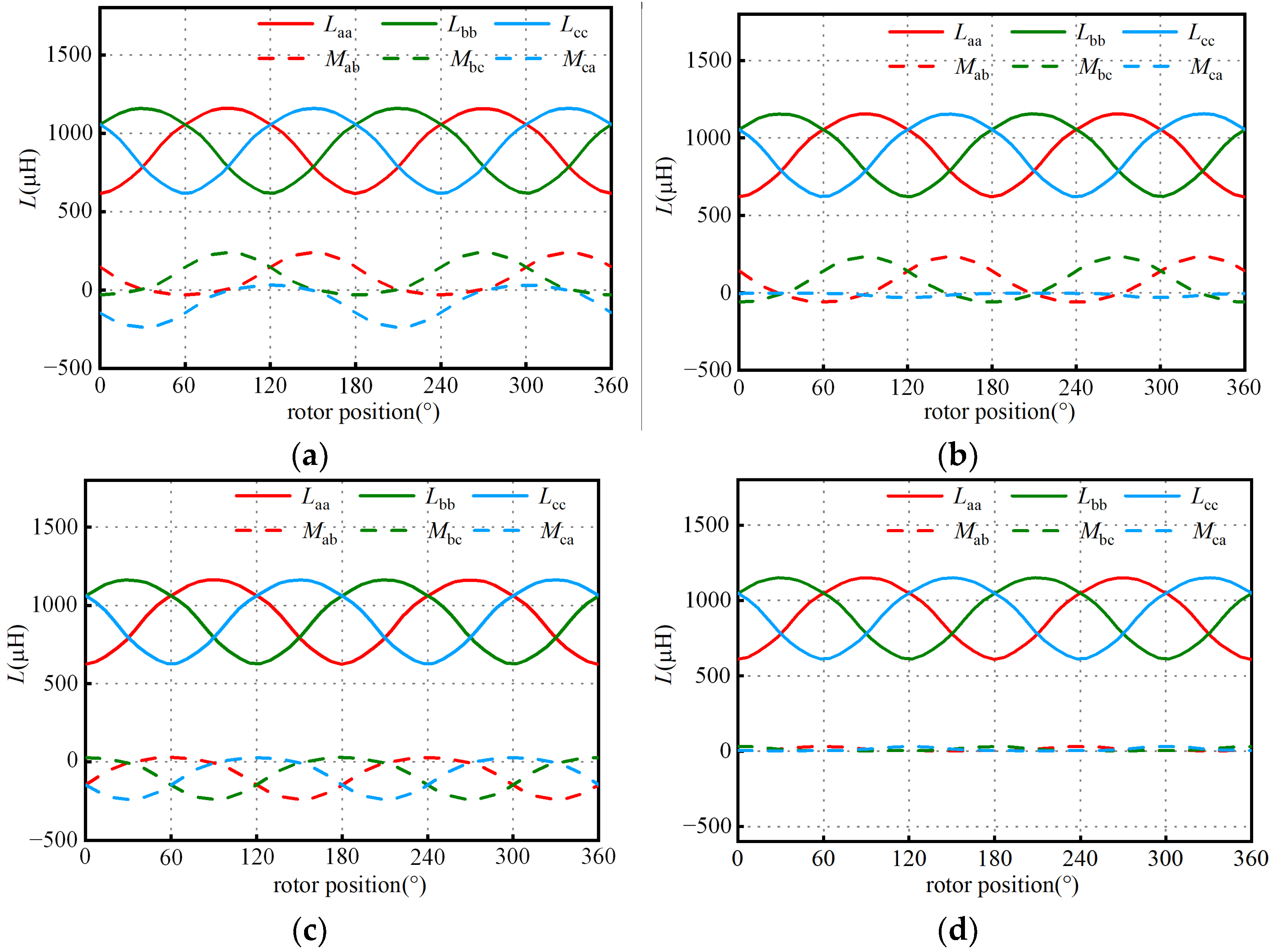
The mutual inductance waveforms between the a-phase search coil of four different structures and the corresponding armature winding are shown in Figure 11. It can be seen that the coupling relationship between the search coils of SSSS and NNNN structures and the armature winding reaches the maximum, and the mutual inductance between the search coils of SSNN and SNSN structures and the armature winding is almost 0, which can reduce the coupling with the armature winding and effectively isolate their signals.
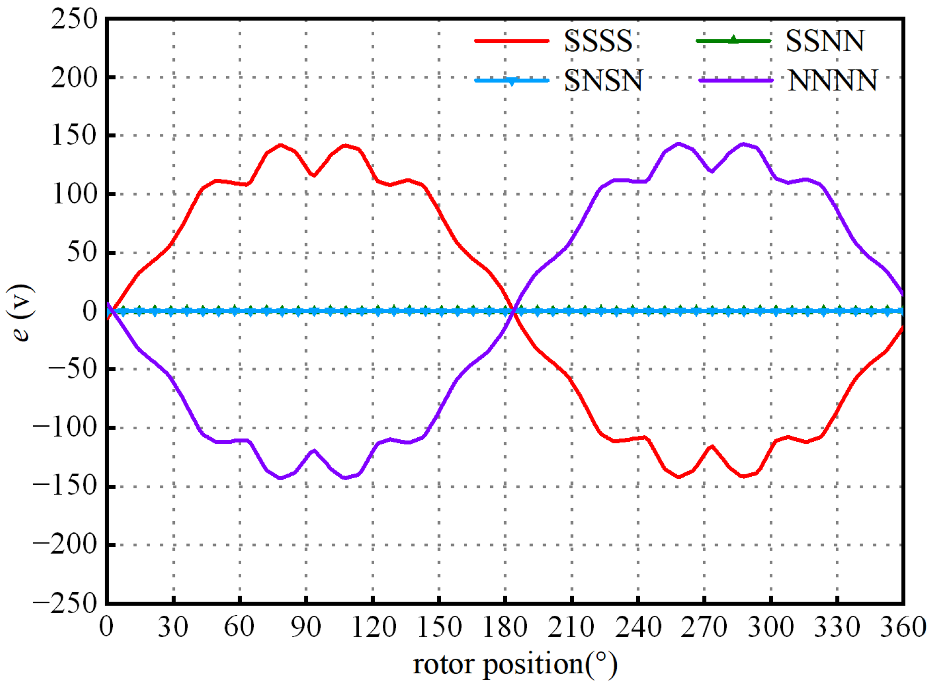
Figure 12 shows the BEMF waveforms of search coils with four different structures, which are consistent with the previous analysis. The BEMF amplitudes of the search coils with SSSS and NNNN structures are the maximum value, and the search coils with SSNN and SNSN structures can offset their BEMF and facilitate the extraction of UHF signals.
The mutual inductance waveform of search coils with SNSN, SSNN, SNSN_1, and SSNN_1 structures are shown in Figure 13. The maximum mutual inductance coupling of any two phases of SNSN structure is obtained. Although the structure of SSNN can reduce the mutual inductance coupling of phase “c” and “a”, the mutual inductance coupling between phase “a” and “b” and phase “b” and “c” reaches the maximum. The mutual inductance of the SNSN_1-structure search coil accounts for 25.8% of its self-inductance, and the mutual inductance of the SSNN_1-structure search coil accounts for 1.3% of its self-inductance. Therefore, it is verified that the structure of the SSNN_1 search coil can reduce the mutual coupling of search coils. The self-inductance corresponding relationship between the final SSNN_1 structure of the search coils and armature winding is shown in Figure 14.
As can be seen from the simulation waveform in Figure 14, the self-inductance Laa, Lbb, and Lcc of the three-phase search coil change under the same law as self-inductance LAA, LBB, and LCC of the armature winding, which can replace the armature winding to extract the rotor position information and estimate the rotor position. At the same time, the search coil self-induction peak-to-peak value is 540 μH at 200 Hz, with a large difference, which can be beneficial to extract the UHF signals.

4.2. Co-Simulation Analysis and Verification

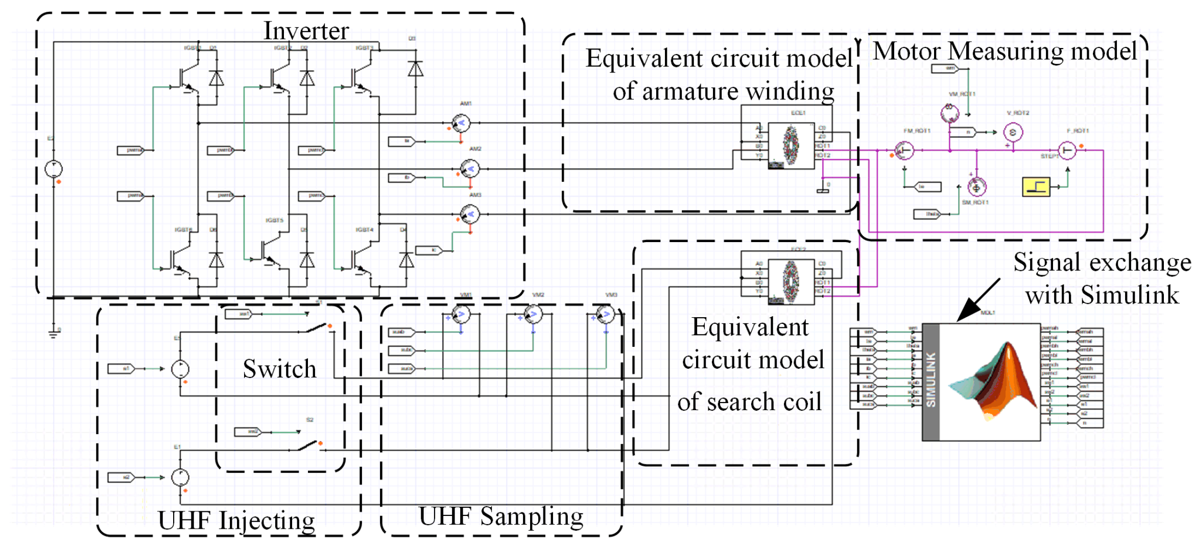
In order to verify the rationality of the method of detecting rotor position with the UHF search coil, Simulink and Simplorer were used to build a co-simulation model to verify the above theory.
Compared with the ideal motor model in Simulink, the FEA model of the motor is used in the co-simulation, which can take into account the influence of the actual electromagnetic parameters on motor control when the motor is running. Moreover, compared with the finite element excitation mode in Maxwell, the power supply of the motor is no longer a sine wave in Simulink, but is the pulse-width modulation wave obtained by the inverter. The effect of the PWM wave on motor operation can be taken into account in the actual control system. Therefore, the results of co-simulation are closer to the actual situation, and the simulation results are more accurate.
The structure diagram of co-simulation is shown in Figure 15. In this paper, the FEA software Maxwell was used to establish the motor model, Simplorer was used to establish the driving circuit, and Simulink was used to establish the control circuit. At this point, Simplorer is equivalent to a bridge between Simulink and Maxwell, and it can connect the three circuits. The control circuit transmits the drive signal to the drive circuit, controls the on–off of the power switch device, and then generates the current excitation to the motor body. At the same time, the UHF signal in the drive circuit injects UHF voltage to the search coil and transmits the feedback signal to the control circuit, and the FEA model transmits the actual rotor position, torque, and speed signals to the control circuit. However, when the FEA model provided by Maxwell was connected with Simplorer, the co-simulation speed was too slow due to the small magnetic field division and control circuit step size. Therefore, the FEA model of the motor in the co-simulation was replaced by the equivalent circuit extraction (ECE) scanning method.
When ECE is used to extract the equivalent circuit model, ECE3 and ECER modules are mainly used for extraction because the motor is a nonlinear model. From the above analysis, it can be seen that the mutual inductance between the armature winding and search coil is zero, and the two exist independently. In addition, since the ECE3 module can only scan three-phase motors, two ECE3 modules were selected in this section to scan the armature winding and search coil, respectively.
In the previous analysis, Maxwell software was used to build the FEA model of PMSM and select the appropriate connection mode of the search coils. Now, taking the motor rated speed of n = 3000 r/min and rated load of TL = 58 N·m as an example, the equivalent circuit model of armature winding and search coils is extracted, and the proposed rotor position detection method is simulated and verified. The driving circuit is shown in Figure 16.
The UHF line voltage signal waveform extracted when the UHF sinusoidal voltage is injected into the search coil in the sequence of phase “a” and “b”, phase “b” and “c”, and phase “a” and “b” is shown in Figure 17.
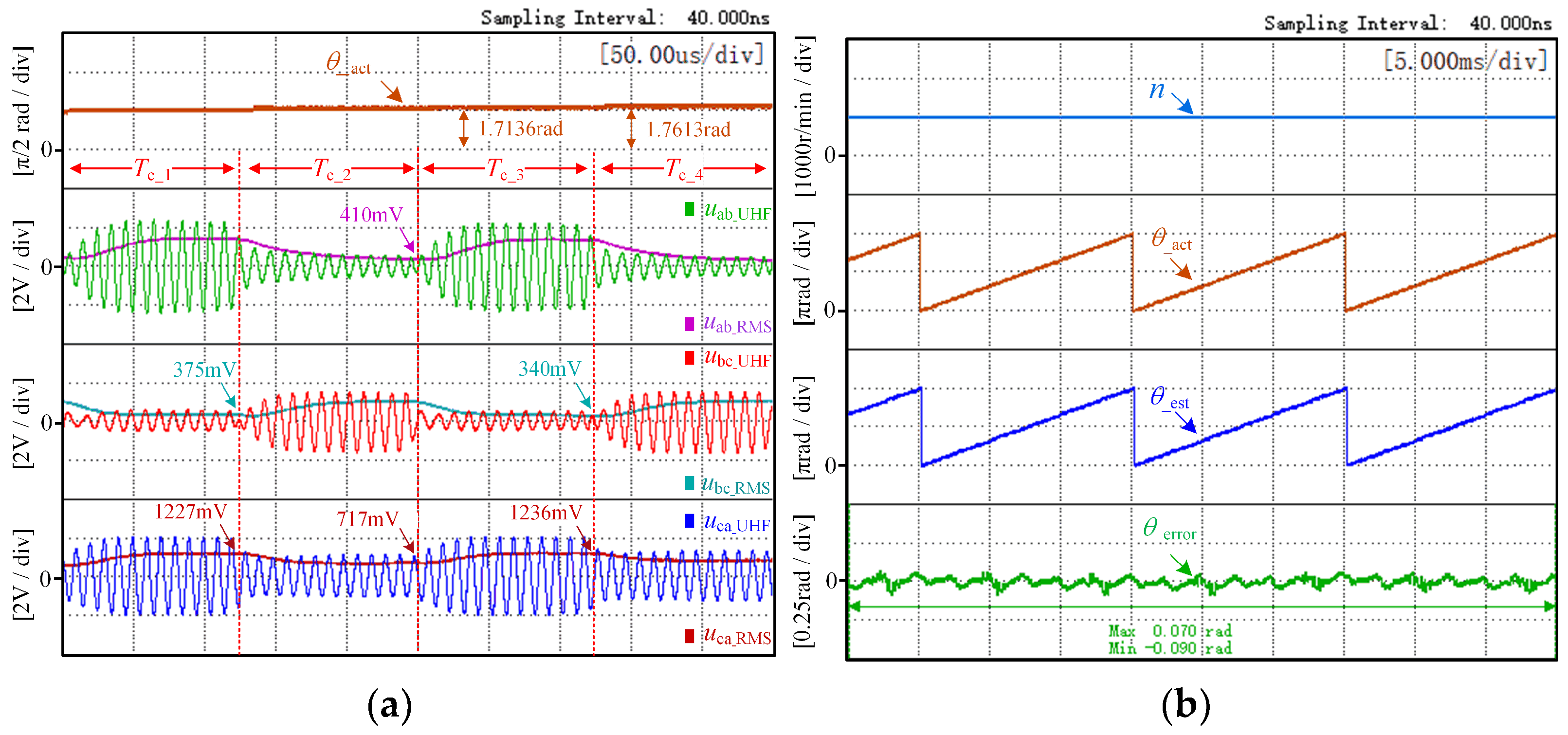
When the motor runs within the control cycle Tc_1, uab_UHF is injected into phase “a” and “b” of the search coil, and the RMS voltage of phase “c, a” uca_RMS and phase “b, c” ubc_RMS are sampled at the end of Tc_1, that is
{ u ca _ RMS ( θ Δ θ ) = 2.144   V u bc _ RMS ( θ Δ θ ) = 1.397   V
Substituting Equation (20) into Equation (4), k1 is
k 1 = U ca _ RMS ( θ Δ θ ) U bc _ RMS ( θ Δ θ ) = 1.535
When the motor runs within the control cycle Tc_2, ubc_UHF is injected into phase “b” and “c” of the search coil, and the RMS voltage of phase “a, b” uab_RMS and phase “c, a” uca_RMS are sampled at the end of Tc_2, that is
{ u ab _ RMS ( θ ) = 1.750   V u ca _ RMS ( θ ) = 1.786   V
Substituting Equation (22) into Equation (6), k2 is
k 2 = U ab _ RMS ( θ ) U ca _ RMS ( θ ) = 0.980
Therefore, according to Equation (8), it can be seen that combining (21) and (23), the rotor position at the end of Tc_2 can be calculated as 1.583 rad (90.71°); at the same time, the actual rotor position is 1.571 rad (90.01°), the position electrical angle error for these two control cycles is 0.7 degrees, and the position error is small.
When the motor runs within the control cycle Tc_3, uab_UHF is injected into phase “a” and “b” of the search coil, and the RMS voltage of phase “c, a” uca_RMS and phase “b, c” ubc_RMS are sampled at the end of Tc_3, that is
{ u ca _ RMS ( θ ) = 2.172   V u bc _ RMS ( θ ) = 1.363   V
According to Equation (9), k1 and k2 are
{ k 2 = U ab _ RMS ( θ Δ θ ) U ca _ RMS ( θ Δ θ ) = 0.980 k 1 = U ca _ RMS ( θ ) U bc _ RMS ( θ ) = 1.594
Substituting Equation (25) into Equation (10), the rotor position at the end of Tc_3 can be calculated as 1.740 rad (99.69°); at the same time, the actual rotor position is 1.729 rad (99.06°). The position electrical angle error for these two control cycles is 0.63 degrees. This proves that the error between the estimated angle and the actual angle is small.
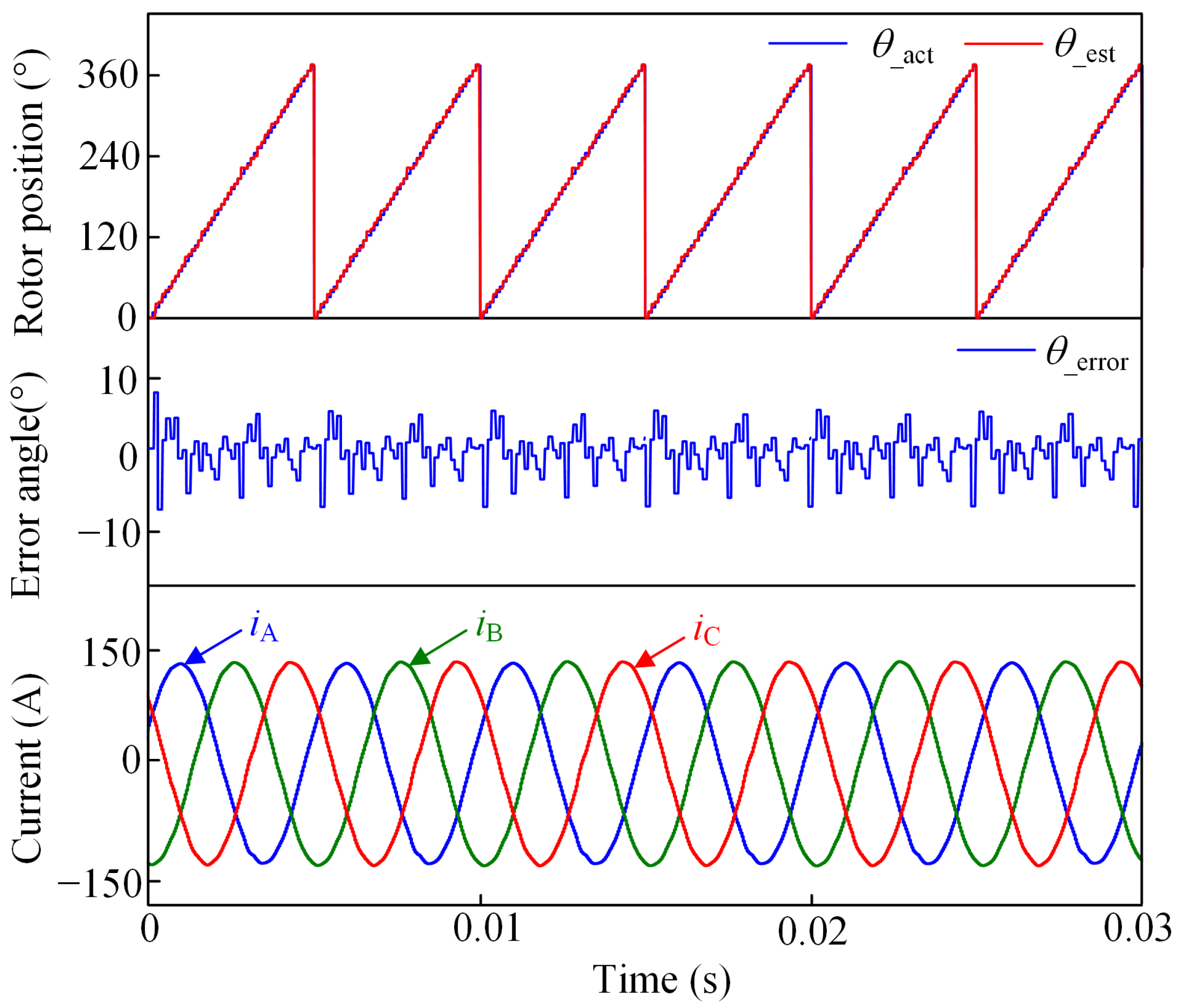
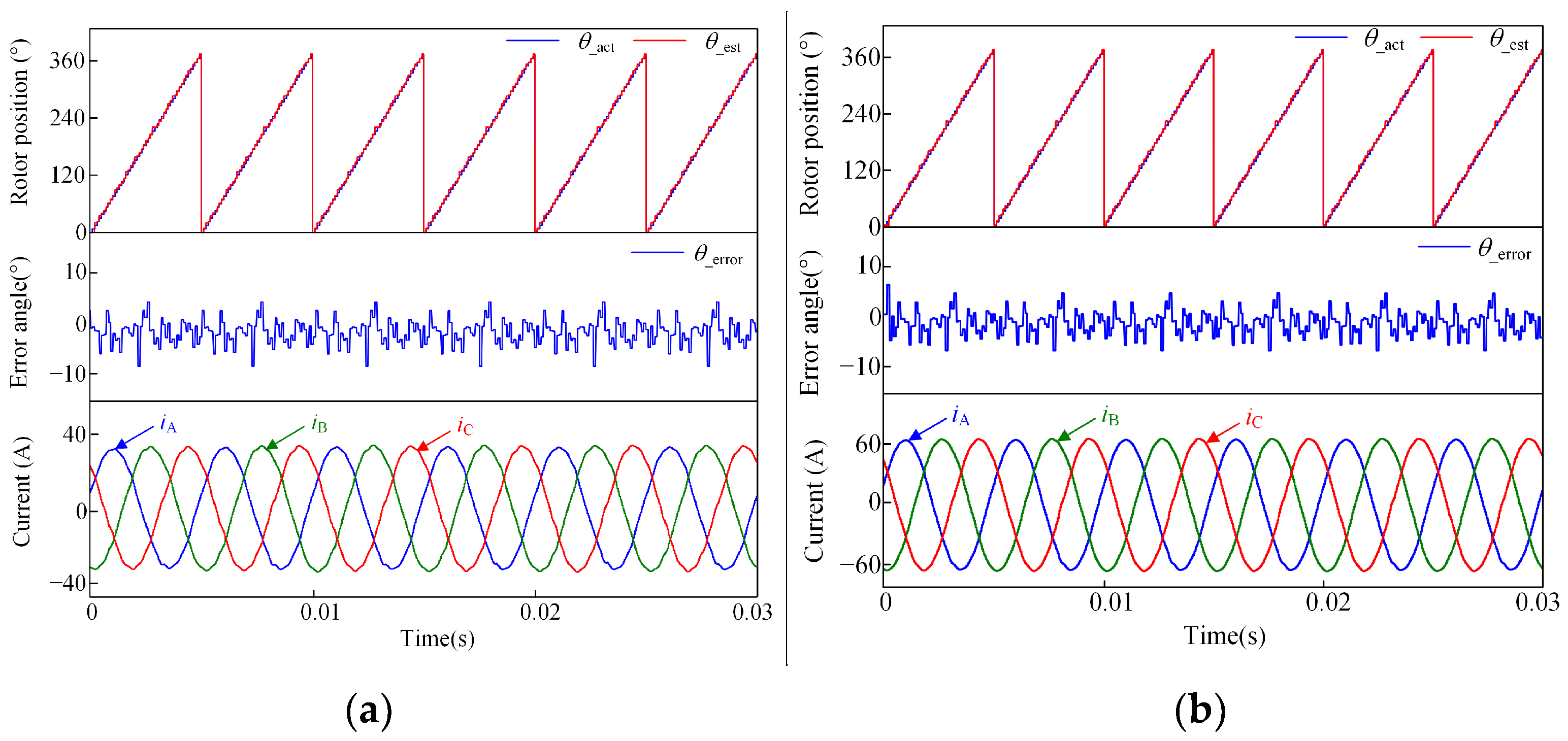
According to the above calculation method, Figure 18 shows the actual rotor position θ_act and the UHF-search coil-estimation rotor position θ_est. At the rated speed of n = 3000 r/min and rated load of TL = 58 N·m, the angle error θ_error is less than 8°; therefore, the UHF search coil can accurately track the rotor position. Meanwhile, in order to prove that the UHF search coil can be applied to the motor drive system, Figure 18 further shows the stator currents iA, iB, and iC generated when the estimated rotor position is fed back to the drive circuit. It can be seen that the three-phase stator currents all have sinusoidal periodic changes, so the UHF search coil can detect the rotor position and control the drive circuit to generate stator current simultaneously.
In order to verify that the UHF search coil can detect the rotor position in the full speed domain, Figure 19 shows the comparison between the actual rotor position and the estimated rotor position of the UHF search coil when rotor speeds are n = 1000 r/min, n = 500 r/min, and n = 100 r/min, respectively, and the motor is at full load. Although the inductance signal of the search coil is not affected by rotational speed, the inductance frequency is twice that of motor frequency, and the change speed is fast, while the frequency of the UHF voltage signal is 100 kHz, providing a wide range of detection bandwidth. As can be seen from Figure 19, the search coil can track the rotor position well when the motor is at different rotational speeds. Moreover, the maximum error electrical angles are 3.2°, 2.1°, and 1.9°, respectively, which are relatively small. Therefore, this method can realize the rotor position detection in the full speed domain.
Figure 20 shows the comparison between the actual rotor position and the estimated rotor position of the UHF search coil, and the corresponding stator currents iA, iB, and iC under light load and half load in turn, and the motor is at rated speed. It can be seen from Figure 20 that the three-phase stator currents are also sinusoidal periodic changes, so different loads applied to the motor will not affect the detection of the rotor position of the motor.
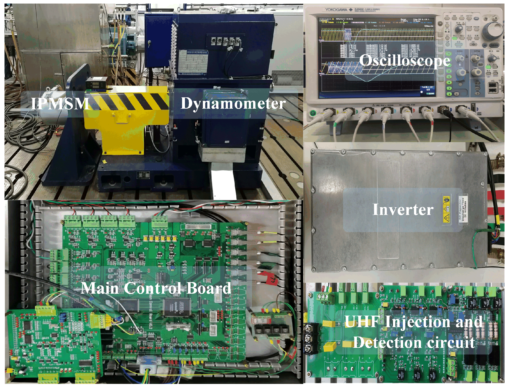
At the same time, in order to verify that the detected position by injecting UHF signals is applicable in the full speed range, we conducted the following experiments for the rotor speeds at n = 3000 r/min, n = 2000 r/min, n = 1000 r/min, and n = 500 r/min, respectively, by injecting UHF signals into the armature winding when the motor was powered off. The photo of the experimental prototype is presented in Figure 21. The control frequency of the controller was Tc = 8 kHz. To simulate the load, an induction motor driven by an ABB inverter was used as a dynamometer. The experimental results were acquired by a Yokogawa DLM4058 digital oscilloscope.
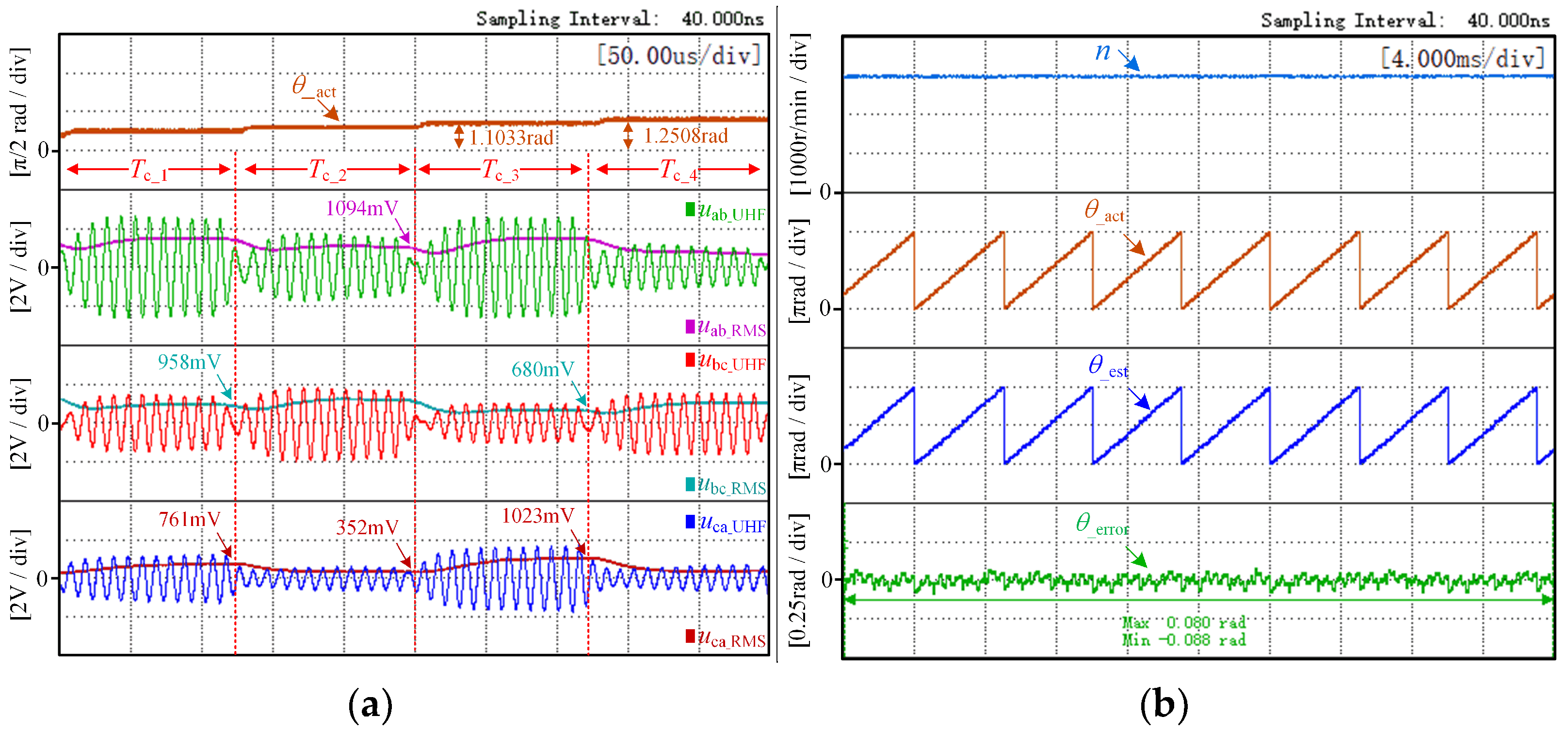
When the motor is at the rated speed (n = 3000 r/min), the UHF component of any two-phase line voltage and the RMS value of the UHF component for four control periods are shown in Figure 22a.
As shown in Figure 22a, by sampling the RMS value of the UHF sinusoidal voltage at the end moments of the two control periods Tc_1 and Tc_2, we can obtain the following ratio according to Equations (4) and (6):
{ k 1 = 761 / 958 = 0.794 k 2 = 1094 / 352 = 3.108
Substituting Equation (26) into Equation (8), the rotor position at the end of Tc_2 can be calculated as 1.0583 rad (60.64°); at the same time, the actual rotor position is 1.1033 rad (63.21°), the position electrical angle error is 2.57 degrees, and the position error is small.
By sampling the RMS value of the UHF sinusoidal voltage at the end moments of control period Tc_3, k1 is updated, and according to Equation (9), k1 and k2 are
{ k 1 = 1023 / 680 = 1.504 k 2 = 1094 / 352 = 3.108
Substituting Equation (27) into Equation (10), the rotor position at the end of Tc_3 can be calculated as 1.3028 rad (74.64°); at the same time, the actual rotor position is 1.2508 rad (71.67°), and the position electrical angle error is 2.97 degrees.
Figure 22b is the waveform diagram of motor speed, the comparison between the actual and estimated position of the rotor, and the position angle error when the motor is at rated speed. It follows that the estimated position is a good way to track the actual position.
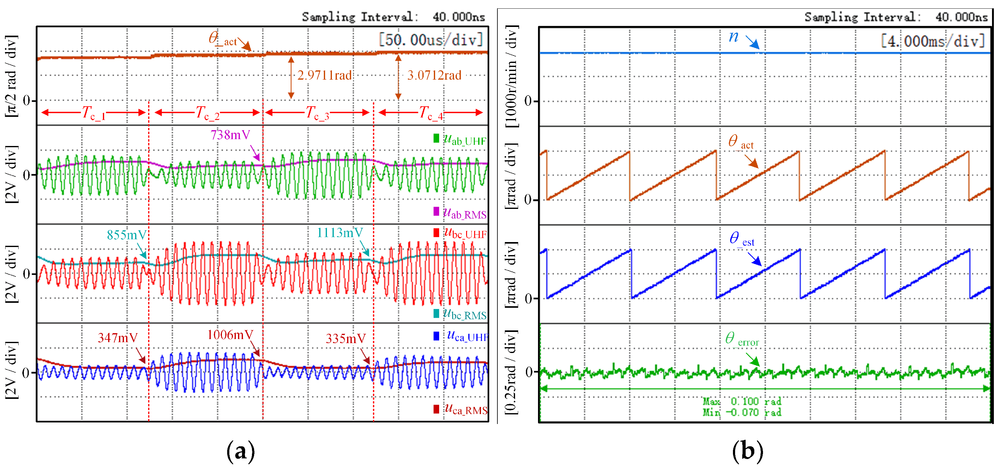
When n = 2000 r/min, the UHF component of any two-phase line voltage and the RMS value of the UHF component for four control periods are shown in Figure 23a. Correspondingly, Figure 23b is the waveform diagram of the motor speed, the comparison between the actual and estimated position of the rotor, and the position angle error.
When n = 1000 r/min, the UHF component of any two-phase line voltage and the RMS value of the UHF component for four control periods are shown in Figure 24a. Correspondingly, Figure 24b is the waveform diagram of the motor speed, the comparison between the actual and estimated position of the rotor, and the position angle error.
When n = 500 r/min, the UHF component of any two-phase line voltage and the RMS value of the UHF component for four control periods are shown in Figure 25a. Correspondingly, Figure 25b is the waveform diagram of the motor speed, the comparison between the actual and estimated position of the rotor, and the position angle error.
The above experimental waveform verifies that when the motor is powered off, the armature winding can detect the rotor position in the full speed domain when the UHF signal is injected into the armature winding.
The search coil is similar to the power-off armature winding and does not participate in the operation of the driving motor. When the inductance of the search coil changes with the rotor in the same way as the armature winding, the rotor position information will be detected by injecting the UHF signal into the search coil, so the search coil can detect the rotor position instead of the armature winding. Although the current conditions do not support experimental verification of the search coil, a prototype will be manufactured in the future to verify the feasibility of the proposed method.

5. Conclusions

In order to improve the reliability of drones’ electric propulsion system operation, IPMSM with high reliability is studied in this paper. This paper proposes to inject a UHF signal into the search coil to detect the rotor position at the full speed domain because the traditional position sensor of the IPMSM is affected by the environment, and the traditional search coil has a small application range. The proposed method has the following advantages:
  • The search coil self-inductance is large and can sensitively reflect the rotor position;
  • Mutual inductance between the search coil and armature winding is small, and the coupling relationship between the two coils reaches the minimum, which does not affect the normal operation of the motor drive system;
  • The equivalent circuit model with the calculation of UHF signal injection into the search coil is simplified because the search coil has less mutual inductance between phases;
  • By searching the mapping relationship between search coil self-inductance and rotor position, as well as the wide detection bandwidth provided by the UHF signal, the rotor position can be detected in the full speed domain and under different loads.

Author Contributions

Data curation, X.L.; formal analysis, H.W. (Huan Wang); funding acquisition, W.C. and X.L; investigation, H.W. (Huimin Wang) and L.G.; methodology, H.W. (Huan Wang); project administration, W.C. and X.L.; resources, L.G.; validation, L.G. and H.W. (Huan Wang); writing—original draft, H.W. (Huan Wang); writing—review and editing, H.W. (Huimin Wang) and X.L. All authors have read and agreed to the published version of the manuscript.

Funding

This research was supported by the National Natural Science Foundation of China under grants 52077155 and 52077156 and in part by the Key Program of Tianjin Natural Science Foundation under grant 20JCZDJC00020.

Institutional Review Board Statement

Not applicable.

Informed Consent Statement

Not applicable.

Data Availability Statement

Not applicable.

Acknowledgments

We extend our sincere thanks to all those who have contributed to this article.

Conflicts of Interest

The authors declare no conflict of interest.

References

  1. Medeiros, R.L.V.; Ramos, J.G.G.S.; Nascimento, T.P.; Filho, A.C.L.; Brito, A.V. A Novel Approach for Brushless DC Motors Characterization in Drones Based on Chaos. Drones 2018, 2, 14. [Google Scholar] [CrossRef] [Green Version]
  2. Li, J.; Yang, J.; Zhang, H. Research on Modeling and Fault-Tolerant Control of Distributed Electric Propulsion Aircraft. Drones 2022, 6, 78. [Google Scholar] [CrossRef]
  3. Urquhart, I.; Tanaka, D.; Owen, R.; Zhu, Z.Q.; Wang, J.B.; Stone, D.A. Mechanically actuated variable flux IPMSM for EV and HEV applications. World Electr. Veh. J. 2013, 6, 684–695. [Google Scholar] [CrossRef]
  4. Riaz, S.; Qi, R.; Tutsoy, O.; Iqbal, J. A novel adaptive PD-type iterative learning control of the PMSM servo system with the friction uncertainty in low speeds. PLoS ONE 2023, 18, e0279253. [Google Scholar] [CrossRef]
  5. Saleem, O.; Abbas, F.; Iqbal, J. Complex Fractional-Order LQIR for Inverted-Pendulum-Type Robotic Mechanisms: Design and Experimental Validation. Mathematics 2023, 11, 913. [Google Scholar] [CrossRef]
  6. Kim, J.K.; Joo, S.W.; Hahn, S.C. Static characteristics of linear BLDC motor using equivalent magnetic circuit and finite element method. IEEE Trans. Magn. 2004, 40, 742–745. [Google Scholar] [CrossRef]
  7. Chen, S.H.; Liu, G.; Zhu, L.Q. Control Strategy of a 315 kW High-Speed BLDC Motor Based on a Speed-Independent Flux Linkage Function. IEEE Trans. Ind. Electron. 2017, 64, 8607–8617. [Google Scholar] [CrossRef]
  8. Liu, G.; Chen, B.; Song, X. High-Precision Speed and Position Estimation Based on Hall Vector Frequency Tracking for PMSM With Bipolar Hall-Effect Sensors. IEEE Sens. J. 2019, 19, 2347–2355. [Google Scholar] [CrossRef]
  9. Cui, C.; Liu, G.; Wang, K.; Song, X. Sensorless Drive for High-Speed Brushless DC Motor Based on the Virtual Neutral Voltage. IEEE Trans. Power Electron. 2015, 30, 3275–3285. [Google Scholar] [CrossRef]
  10. Lee, W.J.; Sul, S.K. A new starting method of BLDC motors without position sensor. IEEE Ind. Appl. Conf. 2004, 4, 2397–2402. [Google Scholar] [CrossRef]
  11. Liu, Y.; Wang, M.; Xu, L. Sensorless control of BLDC motor from zero to low speed based on rotor saliency. In Proceedings of the 2014 IEEE Conference and Expo Transportation Electrification Asia-Pacific (ITEC Asia-Pacific), Beijing, China, 31 August–3 September 2014. [Google Scholar] [CrossRef]
  12. Jang, G.H.; Kim, M.G. Optimal Commutation of a BLDC Motor by Utilizing the Symmetric Terminal Voltage. IEEE Trans. Magn. 2006, 42, 3473–3475. [Google Scholar] [CrossRef]
  13. Hinkkanen, M.; Saarakkala, S.E.; Awan, H.A. Observers for Sensorless Synchronous Motor Drives: Framework for Design and Analysis. IEEE Trans. Ind Appl. 2018, 54, 6090–6100. [Google Scholar] [CrossRef] [Green Version]
  14. Consoli, A.; Cavallaro, C.; Scarcella, G. Sensorless torque control of Syncrel motor drives. IEEE Trans. Power Electron. 2000, 15, 28–35. [Google Scholar] [CrossRef]
  15. Consoli, A.; Scarcella, G.; Testa, A. Slip frequency detection for indirect field oriented control drives. IEEE Ind Appl. 2004, 40, 194–201. [Google Scholar] [CrossRef]
  16. Da, Y.; Shi, X.; Krishnamurthy, M. A New Approach to Fault Diagnostics for Permanent Magnet Synchronous Machines Using Electromagnetic Signature Analysis. IEEE Trans. Power Electron. 2013, 28, 4104–4112. [Google Scholar] [CrossRef]
  17. Da, Y.; Shi, X.; Krishnamurthy, M. A Novel Universal Sensor Concept for Survivable PMSM Drives. IEEE Trans. Power Electron. 2013, 28, 5630–5638. [Google Scholar] [CrossRef]
  18. Da, Y.; Shi, X.; Krishnamurthy, M. Position and current estimation for Permanent Magnet Synchronous Machines using search coils. In Proceedings of the 2011 IEEE Vehicle Power and Propulsion Conference, Chicago, IL, USA, 6–9 September 2011. [Google Scholar] [CrossRef]
  19. Tornello, L.D. Combined Rotor-Position Estimation and Temperature Monitoring in Sensorless Synchronous Reluctance Motor Drives. IEEE Trans. Ind. Appl. 2019, 55, 3851–3862. [Google Scholar] [CrossRef]
  20. Kwon, Y.C.; Sul, S.K.; Baloch, N.A.; Morimoto, S. Design, Modeling, and Control of an IPMSM with an Asymmetric Rotor and Search coils for Absolute Position Sensorless Drive. IEEE Trans. Ind. Appl. 2016, 52, 3839–3850. [Google Scholar] [CrossRef]
  21. Li, G.; Xu, J.D.; Cheng, Z.J. Position Sensorless Based on the Added Coil for Switched Reluctance Motor. Small Spec. Elect. Mach. 2016, 44, 51–54. [Google Scholar]
  22. Mao, L.M.; Jing, Y.Z.; Fan, X.M. Study on Application of Indirect Rotor-Position Detecting Technique with Opposite-Connect Sensing Coils Method in SRD Generator System. Proc. CSEE 2000, 20, 27–34. [Google Scholar]
  23. Liu, C.; Feng, L.; Zhou, Q. Rotor Position Eigenvalue detection for SRD based on Opposite-Connect Sensing Coils Technique. Trans. China Electrotech. Soc. 2008, 23, 24–29. [Google Scholar]
  24. Li, X.M.; Yan, Y.; Xu, Y.M. Low-Speed Rotating Restart and Speed Recording for Free-Running Sensorless IPMSM Based on Ultrahigh Frequency Sinusoidal Wave Injection. IEEE Trans. Power Electron. 2022, 12, 15245–15259. [Google Scholar] [CrossRef]
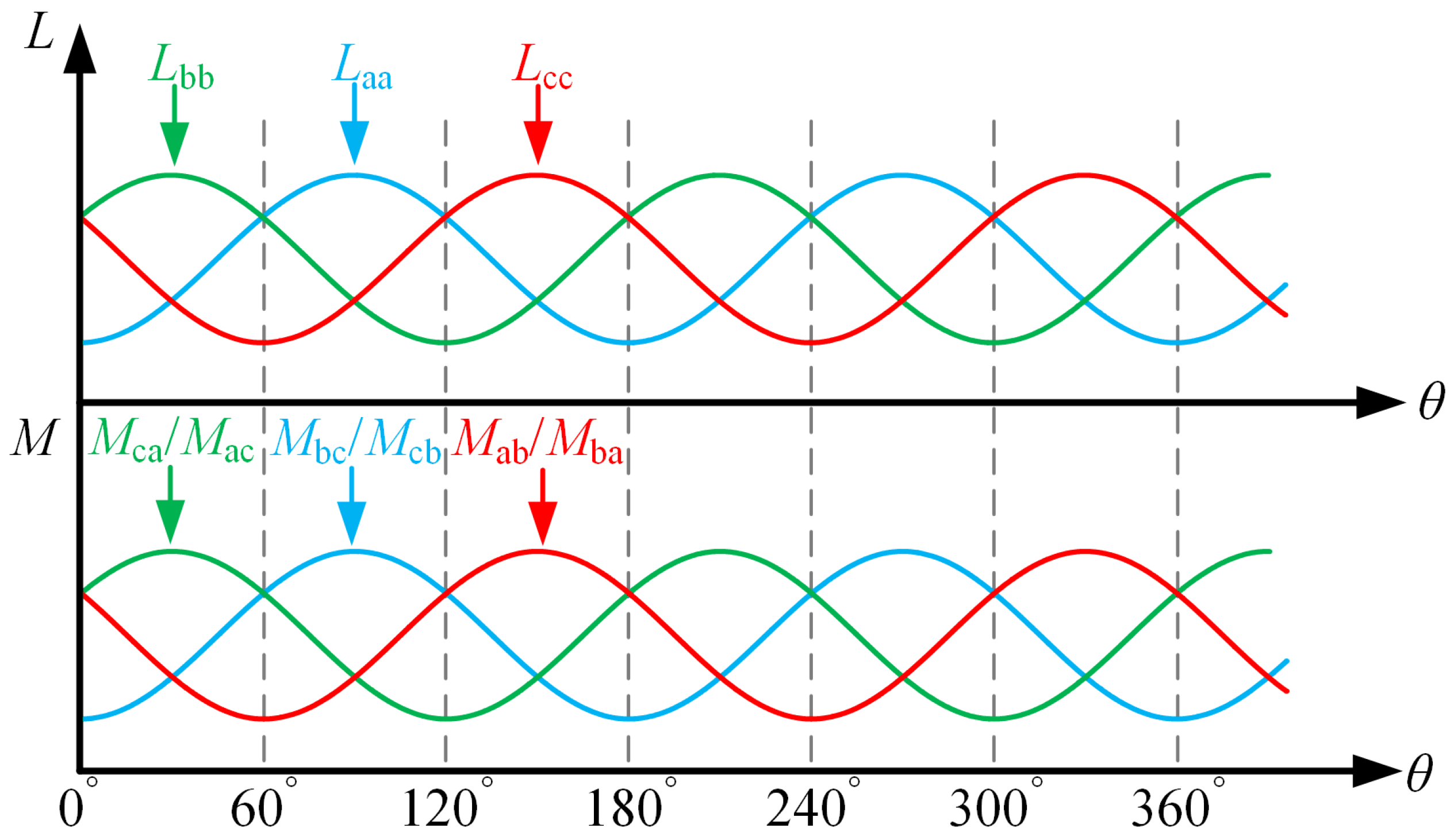
Figure 1. Diagram of the correspondence between search coil inductance and rotor position.
Drones 07 00181 g001
Figure 2. The motor system topology of the proposed method.
Drones 07 00181 g002
Figure 3. Equivalent circuit of phase “a, b” search coil injecting ultrahigh frequency (UHF) signal.
Drones 07 00181 g003
Figure 4. UHF sinusoidal voltage injection sequence.
Drones 07 00181 g004
Figure 5. UHF signal simplified circuit: (a) injecting phase “a” and “b” search coil; (b) injecting phase “b” and “c” search coil.
Drones 07 00181 g005
Figure 6. Diagram of search coil placement.
Drones 07 00181 g006
Figure 7. Search coil structure diagram.
Drones 07 00181 g007
Figure 8. Search coil different connections diagram: (a) SSSS; (b) SSNN; (c) SNSN; (d) NNNN.
Drones 07 00181 g008
Figure 9. Three-phase search coil connection diagram: (a) SNSN; (b) SSNN; (c) SNSN_1; (d) SSNN_1.
Drones 07 00181 g009
Figure 10. Diagram of experimental system.
Drones 07 00181 g010
Figure 11. Search coil and armature winding mutual inductance.
Drones 07 00181 g011
Figure 12. BEMF waveform of different structures of search coil.
Drones 07 00181 g012
Figure 13. Search coil mutual inductance waveform: (a) SNSN; (b) SSNN; (c) SNSN_1; (d) SSNN_1.
Drones 07 00181 g013
Figure 14. Correspondence of self-inductance between search coils and armature windings.
Drones 07 00181 g014
Figure 15. Co-simulation structure diagram.
Drones 07 00181 g015
Figure 16. Co-simulation circuit.
Drones 07 00181 g016
Figure 17. UHF signal injection and detection waveform.
Drones 07 00181 g017
Figure 18. Simulation waveform of rotor position comparison, error angle, and stator current.
Drones 07 00181 g018
Figure 19. Rotor position comparison at different speeds: (a) n = 1000 r/min; (b) n = 500 r/min; (c) n = 100 r/min.
Drones 07 00181 g019
Figure 20. Rotor position comparison at different loads: (a) TL = 14 N·m; (b) TL = 29 N·m.
Drones 07 00181 g020
Figure 21. The photo of the experimental prototype.
Drones 07 00181 g021
Figure 22. Experimental results at n = 3000 r/min: (a) actual position, line voltage and RMS value; (b) speed, rotor position comparison and position angle error.
Drones 07 00181 g022
Figure 23. Experimental results at n = 2000 r/min: (a) actual position, line voltage and RMS value; (b) speed, rotor position comparison and position angle error.
Drones 07 00181 g023
Figure 24. Experimental results at n = 1000 r/min: (a) actual position, line voltage and RMS value; (b) speed, rotor position comparison and position angle error.
Drones 07 00181 g024
Figure 25. Experimental results at n = 500 r/min: (a) actual position, line voltage and RMS value; (b) speed, rotor position comparison and position angle error.
Drones 07 00181 g025
Table 1. The parameters of the IPMSM.
ParametersSymbolValueUnit
Pole pairsp4-
Slotss48-
Rated powerP18kW
Rated speedn3000r/min
Rated torqueTe58N·m
Stator inner radiusD0130mm
Rotor outer radiusD1128mm
Turns of search coilsNsc4-
Disclaimer/Publisher’s Note: The statements, opinions and data contained in all publications are solely those of the individual author(s) and contributor(s) and not of MDPI and/or the editor(s). MDPI and/or the editor(s) disclaim responsibility for any injury to people or property resulting from any ideas, methods, instructions or products referred to in the content.