Article

Decoupled Control Design of Aerial Manipulation Systems for Vegetation Sampling Application

by
Zahra Samadikhoshkho
and
Michael Lipsett
*
Mechanical Engineering Department, University of Alberta, 116 St & 85 Ave, Edmonton, AB T6G 2R3, Canada
*
Author to whom correspondence should be addressed.
Drones 2023, 7(2), 110; https://doi.org/10.3390/drones7020110
Submission received: 8 December 2022 / Revised: 1 February 2023 / Accepted: 4 February 2023 / Published: 6 February 2023

Abstract

:
A key challenge in the use of drones for an aerial manipulation task such as cutting tree branches is the control problem, especially in the presence of an unpredictable and nonlinear environment. While prior work focused on simplifying the problem by modeling a simple interaction with branches and controlling the system with nonlinear and non-robust control schemes, the current work deals with the problem by designing novel robust nonlinear controllers for aerial manipulation systems that are appropriate for vegetation sampling. In this regard, two different potential control schemes are proposed: nonlinear disturbance observer-based control (NDOBC) and adaptive sliding mode control (ASMC). Each considers the external disturbances and unknown parameters in controller design. The proposed control scheme in both methods employs a decoupled architecture that treats the unmanned aerial vehicle and the manipulator arm of the sampler payload as separate units. In the proposed control structures, controllers are designed after comprehensively investigating the dynamics of both the aerial vehicle and the robotic arm. Each system is then controlled independently in the presence of external disturbances, unknown parameter changes, and the nonlinear coupling between the aerial vehicle and robotic arm. In addition, fully actuated and underactuated aerial platforms are examined, and their stability and controllability are compared so as to choose the most practical framework. Finally, the simulation findings verify and compare the performance and effectiveness of the proposed control strategies for a custom aerial manipulation system that has been designed and developed for field trials.

1. Introduction

Aerial manipulation systems (AMSs) are increasingly popular for academic research and industrial purposes. AMSs have been designed for use in a variety of applications, including transporting objects [1], inspection [2], fetching [3], turning valves [4], door opening [5], perching [6], grasping, and manipulation [7]. The high demand for vegetation sampling and the associated difficulties of the task have lately attracted attention to using AMSs for this purpose [8,9,10,11,12]. Despite early efforts to develop an efficient AMS for vegetation sampling, the technology is still in its early stage. A significant concern when cutting tree branches is the control of the AMS, particularly during contact with an unknown and nonlinear environment.
Aerial manipulation systems are a type of nonlinear system characterized by unknown dynamics and subject to uncertainties. An AMS comprises a mobile platform with a manipulator and an end effector that may have a varying number of degrees of freedom. The airborne base platform and arm movements provide significant dynamical nonlinearities and couplings. As well, external disturbances produce a high level of uncertainty from a variety of factors, such as the interaction with the environment during contact. These perturbations and unknown parameters degrade the performance and may even affect the stability of the system. For these reasons, minimizing their adverse effects is the primary goal of an AMS control system design.
Numerous strategies for dealing with uncertainty and disturbances in nonlinear systems have been developed. Feedforward techniques may be used to reduce the effect of a measurable disturbance. The direct measurement of external disturbances, on the other hand, is often prohibitively costly or even impossible in some cases [13]. Some researchers focus their efforts on investigations on high-performance or on robust control strategies for dealing with disturbances encountered during the AMS control process. In [14], four control techniques were implemented and compared in the free-flight control of an AMS with coupled dynamics, including the inverse dynamic, hierarchical LQR, adaptive sliding mode, and semi-optimal nonlinear control approaches. The adaptive control strategy described in [15] is another method for dealing with uncertainty. A hierarchical control approach was presented to simplify aerial manipulation system tracking control [16,17,18]. Model-free intelligent control approaches such as Neural Network (NN) control may be used to express uncertainty and reject disturbances. These controllers are capable of dealing with system uncertainties to some extent, but the controllers have several limitations, including a conservative design in robust control, chattering in sliding mode control, stability concerns in adaptive control, and a high computational cost for network training in NN control.
A number of studies on AMS control for the purpose of vegetation sampling appear in the literature. In [8], the physical coupling between an aerial manipulator and a tree was modeled to control the AMS for canopy sampling applications with a conventional PID controller. The interaction model utilized in that research was based on several simplifying assumptions, which did not take into account the effect of disturbances by outside sources, such as wind gusts. In [9], a PID control approach for canopy sampling in both free-flight and arm motion control was presented. The integrator term in the traditional PID improves the disturbance suppression and robustness, but this term also increases the tracking overshoot and degrades the system stability. In [10], a unique aerial manipulator with a front cutting effector and a disturbance observer (DO) was suggested to evaluate external disturbances and correct for them using a sliding mode controller, using a passive cutting tool rather than an active robotic manipulator.
The approach of applying disturbance observer-based (DOB) control for aerial vegetation sampling with an active arm is discussed in this study. DOB control is motivated by the challenges in controlling an AMS with an active robotic arm, by estimating disturbances and uncertainties during the control process and by applying appropriate compensation. Furthermore, in vegetation sampling, the effect of uncertainties can be regarded as external disturbances rather than simulating the simple interaction with the environment. As a result, the DOB control approach can be used for aerial vegetation sampling in the absence of knowledge about the vegetation dynamical behavior.
Adaptive sliding mode control (ASMC) is another effective, robust control technique that can be used in this application. ASMC can deal with a high level of uncertainty and avoid chattering due to its adaptive tuning capability. ASMC was demonstrated to show a superior performance in controlling an AMS (with a coupled dynamics model) over inverse dynamic, hierarchical LQR, and semi-optimal nonlinear control approaches in [14]. However, its performance in decoupled AMS control schemes (which is more straightforward for real-time applications) has yet to be assessed. With this motivation, nonlinear ASMC is developed for the system in the present work. A comparative study is conducted between these two potential control approaches for aerial vegetation sampling missions.
The primary contribution of this study is the development of a nonlinear controller in combination with a nonlinear disturbance observer (NDOB), as well as proposing an ASMC technique suitable for aerial vegetation sampling. A decoupled control framework is proposed by considering the unmanned aerial vehicle (UAV) and active robotic arm as separate components. The performance of the two proposed approaches is compared and verified in a simulation for a laboratory prototype of an AMS. Finally, the most efficient control scheme for aerial vegetation is selected.

2. Modeling of an AMS

This section presents the kinematics and dynamics of the aerial vehicle and its manipulator.

2.1. Kinematic Modeling

To describe the kinematics of the UAV, the inertial frame, F I , and the body frame, F q with the origin of the UAV center of mass, are defined. Position and velocity of the UAV with respect to the inertial frame are denoted as P q = [ x y z ] T and v q = [ v x v y v z ] T , respectively. The attitude of the UAV is expressed by Euler angles as Φ q = [ ϕ θ ψ ] T in which ϕ , θ , and ψ are roll, pitch, and yaw angles, respectively. Rotation matrix from body to inertial frame, R q , is defined in (1):
R q = C ( ψ ) C ( θ ) C ( ψ ) S ( ϕ ) S ( θ ) C ( ϕ ) S ( ψ ) C ( ψ ) C ( ϕ ) S ( θ ) + S ( ϕ ) S ( ψ ) C ( θ ) S ( ψ ) S ( ψ ) S ( ϕ ) S ( θ ) C ( ϕ ) C ( ψ ) C ( ϕ ) S ( ψ ) S ( θ ) S ( ϕ ) C ( ψ ) S ( θ ) C ( θ ) S ( ϕ ) C ( ϕ ) C ( θ ) .
where C ( . ) and S ( . ) represent the c o s and s i n functions, respectively. The position vector and rotation matrix of the end effector (EE) of the manipulator with respect to F I are derived from (2) and (3), respectively:
P e e = P q + R q P e e q ,
R e e = R q R e e q ,
where P e e q and R e e q are the relative position and the rotation matrix of the end effector, described in the body frame of the UAV. The kinematics of the manipulator are described as
T e e q = R e e q P e e q 0 1 × 3 1 .
Here, T e e q denotes the end-effector homogeneous transformation matrix, which is calculated by multiplying the set of mechanism homogeneous transformation matrices as
T e e q = T 1 q ( q 1 ) T 2 1 ( q 2 ) T n n 1 ( q n ) ,
where q i , i = 1 n is the i t h joint variable and n represents the number of joints. The transformation matrix from i t h to i 1 t h frame of the manipulator, T n 1 n ( q n ) , is computed from
T i i 1 ( q i ) = C ( θ i ) S ( θ i ) C ( α i ) S ( θ i ) S ( α i ) a i C ( θ i ) S ( θ i ) C ( θ i ) C ( α i ) C ( θ i ) S ( α i ) a i S ( θ i ) 0 S ( α i ) C ( α i ) d i 0 0 0 1 ,
where θ i , α i , a i , and d i are Denavit–Hartenberg parameters [19].
From the position and orientation of the end effector with respect to the UAV, the relative linear and angular velocity of the end effector in F q can be expressed by
P ˙ e e q = J p q ˙ ,
ω e e q = J o q ˙ ,
where q = [ q 1 q n ] T is the manipulator joint vector and J p and J o represent position and orientation Jacobians:
J p = [ J p 1 J p n ] T ,
J o = [ J o 1 J o n ] T .
Elements of Jacobians are obtained based on the type of joints [19] (prismatic or revolute joint) by
J p i J o i = z i 1 0 3 × 1 for prismatic joint z i 1 × ( P e e q P i 1 ) z i 1 for revolute joint .
where z i 1 is calculated using the third column of the rotation matrix R i 1 q , and P i 1 is the position of the previous joint with respect to the UAV. The linear and angular velocities of the end effector with respect to the inertial frame are found from
P ˙ e e = v q ( R q P e e q ) ω q + R q J p q ˙ ,
ω e e = ω q + R q J o q ˙ ,
where ω q represents the UAV angular velocity, which is determined using the dynamic model of the UAV. Operator ( . ) indicates the skew-symmetric form of the vector or hat map. For example, the skew-symmetric form of matrix a is computed as
a = 0 a 3 a 2 a 3 0 a 1 a 2 a 1 0 .

2.2. Dynamic Modeling

In the decoupled dynamic model of the arm and UAV, the arm and UAV are modeled as independent subsystems, and their interactions are treated as disturbances. In the following section, it is shown that these disturbances are effectively rejected by selecting appropriate control methods. The equations of motion of the UAV for the underactuated platform (i.e., a quadrotor or hexarotor with parallel motors that can generate propulsion only in the z axis) is derived from (15) [20].
P ˙ q = v q , m q v ˙ q = f q R q e 3 + m q g e 3 + Δ p , R ˙ q = R q ( ω q ) , J q ω ˙ q = M q ω q × J q ω q + Δ o ,
where m q and J q are the mass and moment of inertia matrices of the UAV, f q is the position control signal, M q is the attitude control signal, g is the constant gravity acceleration, and e 3 = [ 0 , 0 , 1 ] T . Unmodeled dynamics are represented by Δ p ; Δ o represents external disturbances, such as arm motion effects that can change the location and attitude of the UAV. For a fully actuated UAV (i.e, hexarotor equipped with motors able to generate thrust in the x and y axes), the term f q R q e 3 in (15) should be replaced with R q f q .
To determine the dynamic model of the manipulator in the UAV frame, the kinetic and potential energies of the manipulator linkages and motors are calculated. Kinetic energy of the manipulator is expressed as K = 1 2 q ˙ T H ( q ) q ˙ , in which H ( q ) is expressed as (16) [19]
H ( q ) = i = 1 n m l i J p l i T J p l i + J o l i T R l i I l i R l i T J o l i + i = 1 n m m i J p m i T J p m i + J o m i T R m i I m i R m i T J o m i ,
where l i and m i are terms associated with the i th link and i th motor of the manipulator. For example, m l i , J p l i , R l i , and I l i are mass, position Jacobian, rotation matrix, and moment of inertia for the i th link, respectively.
The potential energy of the manipulator is given in the following expression:
U ( q ) = i = 1 n m l i g e 3 P l i + i = 1 n m m i g e 3 P m i .
where P l i and P m i are position of the i th link and i th motor with respect to the inertial frame. Knowing the kinetic and potential energy of the manipulator, its governing equations are written as
H ( q ) q ¨ + n ( q , q ˙ ) = τ + Δ m ,
where τ is the control signal and Δ m indicates the uncertainties applied to the manipulator. The term n ( q , q ˙ ) is obtained from
n ( q , q ˙ ) = C ( q , q ˙ ) + G ( q ) , C ( i , j ) = 1 2 k = 1 n ( H i j q k + H i k q j H j k q i ) q ˙ k , G ( q ) = ( U ( q ) q ) T .

3. Controller Design

In this section, two control techniques capable of dealing with disturbances and uncertainties in aerial manipulation are designed for the decoupled dynamics of the system that were presented in the preceding section.

3.1. Disturbance Observer-Based Control

Disturbance observer-based controllers are described for both the UAV and its robotic manipulator to control them separately in a decoupled configuration.

3.1.1. UAV Control

Aerial vehicle control should comprise both position and attitude. For an aerial vehicle with an underactuated platform, its attitude cannot be independently controlled. Thus, the control signal acquired from position control should be utilized to determine the desired attitude values. In order to accomplish this, the control algorithm is divided into two loops. Figure 1 shows a high-level block diagram of the suggested control structure for the underactuated UAV. The outer loop controls the UAV position, while the inner loop executes commands received from the outer loop.
For position control of an underactuated UAV, position and velocity errors are expressed as e P = P q P q d and e v = v q v q d , where P q d and v q d denote the desired position and velocity of the UAV, respectively. By defining desired acceleration as a q d , e = e v + k 1 e P and A D O B C in (20), position control signal, f q , is formulated as (21).
A D O B C = m q ( k 1 e v + g e 3 a q d ) k 2 e Δ ^ p ,
f D O B C = A D O B C . R q e 3 ,
where Δ ^ p represents the disturbance estimation derived from (22) and (23). Moreover, k 1 , k 2 , and k p are all positive definite matrices.
Δ ^ p = y p + k p m q e ,
y p ˙ = k p ( m q ( k 1 e v a q d + g e 3 ) f D O B C R q e 3 + Δ ^ p ) e .
Assuming UAV control with the desired direction of the first body-fixed axis as r 1 c , desired rotation matrix and angular velocity are calculated as
R q d = [ r 1 d r 2 d r 3 d ] , r 3 d = A D O B C A D O B C , r 2 d = r 3 d × r 1 c r 3 d × r 1 c , r 1 d = r 3 d × ( r 3 d × r 1 c ) r 3 d × r 1 c ,
ω q d = R q d T R ˙ q d .
To control underactuated UAV attitude, errors in rotation and angular velocity are defined as
e R q = 1 2 ( R q d T R q R q T R q d ) ,
e ω q = ω q R q T R q d T ω q d .
Here, ( . ) is the vee map or inverse of the hat map.
By defining the above errors, one can obtain the attitude control signal as
M D O B C = ω q × J q ω q J q ( ( ω q ) R q T R q d ω q d R q T R q d ω ˙ q d ) K R q e R q K ω q e ω q Δ ^ o ,
Δ ^ o = y o + k o J q e ω q ,
y ˙ o = k 3 J q 1 e R q + e ω q k o ( M D O B C ω q × J q ω q + J q ( ω ^ q R q T R q d ω q d R q T R q d ω ˙ q d ) + Δ ^ o ) ,
where k 3 , k o , K ω q , and K R q are positive definite matrices. For a fully actuated UAV, the position and attitude can be controlled independently. Thus, there is no need to calculate the desired attitude from the position control signal ((24) and (25)). The attitude control signal is the same as (28) to (30). In the position control signal, (21) and (23) should be replaced with (31) and (32), respectively.
f D O B C = R q T A D O B C .
y p ˙ = k p ( m q ( k 1 e v a q d + g e 3 ) R q f D O B C + Δ ^ p ) e .

3.1.2. Arm Control

Arm joint angle error and reference state to control the arm are defined as e q = q q d and q ˙ r = q ˙ d γ e q . The suggested control signal for the arm is as follows:
τ D O B C = H ( q ) q ¨ r + C ( q , q ˙ ) q ˙ r + G ( q ) γ p e q γ v e ˙ q Δ ^ m ,
Δ ^ m = y m + k m q ˙ ,
y ˙ m = k m H ( q ) 1 y m k m ( k m q ˙ C ( q , q ˙ ) q ˙ G ( q ) + τ D O B C + Δ ^ m ) .
The matrices γ , γ p , γ v , and k m are all positive definite.
In this section, two disturbance observer-based controllers are designed to address unmodeled dynamics and disturbances, such as interaction with a branch of a tree. There is no need to model the interaction forces with branches. Existing models to simulate such an interaction (e.g., the one suggested in [8]) are not robust to parameters such as branch shape, diameter, and orientation. These models only consider simplified mass–spring–damper systems with translational compliance to model the branch, and so they are not accurate enough for practical experiments. To model a simplified interaction, the torque of the i th branch can be formulated as [8]
τ b i = K b i θ b i ϕ b i + C b i θ ˙ b i ϕ ˙ b i ,
where θ b i and ϕ b i are branch orientation angles while K b i and C b i present angular stiffness and damping tensors of the i th branch. From this torque model, interaction forces can be expressed as [8]
F c x F c y = 1 L i 1 0 0 sec θ b i τ b i ,
where L i is the length of the i th branch.

3.2. Adaptive Sliding Mode Control

In this section, an ASMC scheme is designed for both the UAV and the manipulator, and the stability of the controller is proved using Lyapunov stability criteria.

3.2.1. UAV Control

Similar to the disturbance observer-based approach for the underactuated aerial platform, the control signal obtained from the position control loop should be used to find desired values for the attitude loop.
To design a position controller, the position tracking error is defined in the same manner as in the preceding section. To find the sliding surface, the derivative of the reference trajectory is determined as
x ˙ r = v q d Λ p e p ,
where x r represents the reference trajectory, v q d denotes the desired linear velocity, and Λ p is a positive definite gain matrix. The sliding surface for UAV position control can be determined as
S p = e p ˙ + Λ p e p .
The underactuated control signal and the adaptation law for updating the uncertainty, Δ ^ p , are designed as follows
A A S M C = ( m q g e 3 m q [ x ¨ r k v e p ˙ k p e p ] + Δ ^ p ) f A S M C = A A S M C . R q e 3 Δ ^ ˙ p = Γ p S p ,
where Γ p should be a positive definite matrix. Substituting the position control signal into the position dynamic equation, the closed-loop dynamic of the position is derived as
m q S p ˙ + k v e p ˙ + k p e p = Δ ˜ p ,
where ( . ) ˜ indicates the uncertainty estimation error. The stability of the proposed control law is proved by introducing the following Lyapunov candidate function.
L p = 1 2 [ S p T m q S p + Δ ˜ T p Γ p 1 Δ ˜ p + e p T ( Λ p k v + k p ) e p ] .
Taking the derivative of the Lyapunov function results in
L ˙ p = S p T m q S ˙ p + Δ ˜ T p Γ p 1 Δ ˜ ˙ p + e p T ( Λ p k v + k p ) e p ˙ .
Considering the closed-loop dynamic of the position, the derivative of the Lyapunov function is rewritten as
L ˙ p = S p T ( k v e p ˙ k p e p + Δ ˜ p ) + Δ ˜ T p Γ p 1 Δ ˜ ˙ p + e p T ( Λ p k v + k p ) e p ˙ .
Substituting the position sliding surface and adaptation law into the above equation yields the following expression:
L ˙ p = e p ˙ T k v e p ˙ e p T Λ p k p e p .
Although (24) and (25) can be used to find the desired angular velocity of the underactuated UAV, a different approach is considered here based on desired Euler angles. By finding the required thrust of the UAV and having the desired heading angle ψ d , the desired roll and pitch angles are computed as
ϕ d = sin 1 A A S M C ( 1 ) f A S M C sin ψ d A A S M C ( 2 ) f A S M C cos ψ d ,
θ d = sin 1 A A S M C ( 1 ) f A S M C cos ψ d + A A S M C ( 2 ) f A S M C sin ψ d cos ϕ d .
The desired angular velocity of the UAV is determined as
ω q d = 1 sin ( ϕ ) tan ( θ ) cos ( ϕ ) tan ( θ ) 0 cos ( ϕ ) sin ( ϕ ) 0 sin ( ϕ ) cos ( θ ) cos ( ϕ ) cos ( θ ) ] 1 ϕ d ϕ θ d θ ψ d ψ .
Angular velocity error, e ω , reference angular velocity, ω r , attitude sliding surface, S o , and attitude uncertainty estimation, Δ ^ o , are defined as follows to control the attitude of the UAV
e ω = ω q ω q d ,
ω ˙ r = ω ˙ q d Λ o e ω d t ,
S o = e ω + Λ o e ω d t ,
Δ ^ ˙ o = Γ o S o .
Here, Λ o and Γ o are positive definite gain matrices. Finally, the attitude control signal, M A S M C , is derived as
M A S M C = J q ω ˙ r + ω q × J q ω q k p o e ω k i e ω d t + Δ ^ o ,
where k p o and k i are positive matrices. The stability of the attitude control loop is demonstrated using the following Lyapunov function:
L o = 1 2 [ S o T J q S o + Δ ˜ T o Γ o 1 Δ ˜ o + e ω T d t ( Λ o k p o + k i ) e ω d t ] .
Similar to the position control formulation, the closed-loop dynamics of the attitude control loop are expressed as
J q S ˙ o + k p o e ω + k i e ω d t = Δ ˜ o .
Taking the time derivative of the attitude Lyapunov function and considering the attitude closed-loop dynamics gives the following expression:
L ˙ o = S o T ( k p o e ω k i e ω d t + Δ ˜ o ) + Δ ˜ T o Γ o 1 Δ ˜ ˙ o + e ω T d t ( Λ o k p o + k i ) e ω .
Considering the definition of S o and the attitude adaptation law, the Lyapunov function simplifies as
L ˙ o = e ω T k p o e ω e ω T d t Λ o k i e ω d t .
For the fully actuated UAV, there is no need to find (46) and (47). However, (40) should be replaced with (58).
A A S M C = ( m q g e 3 m q [ x ¨ r k v e p ˙ k p e p ] + Δ ^ p ) f A S M C = R q T A A S M C Δ ^ ˙ p = Γ p S p ,

3.2.2. Arm Control

Similar to UAV control, an adaptive sliding mode method is utilized in the design of arm control. The control signal is given as
e q = q q d ,
q ˙ r = q ˙ d Λ q e q ,
S q = e ˙ q + Λ q e q ,
τ A S M C = H q ¨ r + C q ˙ r + G k v q e ˙ q k p q e q + Δ ^ m ,
Δ ^ ˙ M = Γ q S q ,
where Λ q , k v q , k p q , and Γ q are positive definite matrices. In order to prove the stability of the arm controller, the following Lyapunov function is considered
L q = 1 2 [ S q T H S q + Δ ˜ T q Γ q 1 Δ ˜ q + e q T ( Λ q k v q + k p q ) e q ] .
In a similar fashion to the UAV stability proof, the closed-loop dynamics of the arm need to be found.
H S ˙ q + C S q + k v q e ˙ q + k p q e q = Δ ˜ q .
Taking the derivative of the Lyapunov function with respect to time and considering closed-loop dynamics, sliding surface definition, and adaptation law, the following equation is written:
L ˙ q = e q ˙ T k v q e q ˙ e q T Λ q k p q e q .

4. Simulation Results

This section discusses the performance of the proposed controllers in addition to the stability and controllability of aerial platforms for vegetation sampling. Figure 2 is a photograph of a prototype of the aerial manipulation system developed at the University of Alberta for aerial vegetation sampling. The developed platform comprises a modified DJI S1000 equipped with a custom three-degrees-of-freedom robotic arm and a cutting mechanism at the distal end.

4.1. Helical Trajectory

In the first scenario, a challenging helix trajectory is considered for testing the performance of the controllers that have been designed for UAV motion control. In this simulation scenario, the position of the UAV in the x direction increases steadily as the UAV follows a sinusoidal trajectory in the other two directions. Significant sinusoidal external disturbances are applied as external forces and moments to the UAV equations of motion to evaluate the effectiveness of the suggested controllers in the presence of uncertainties and disturbances.

4.1.1. Underactuated UAV

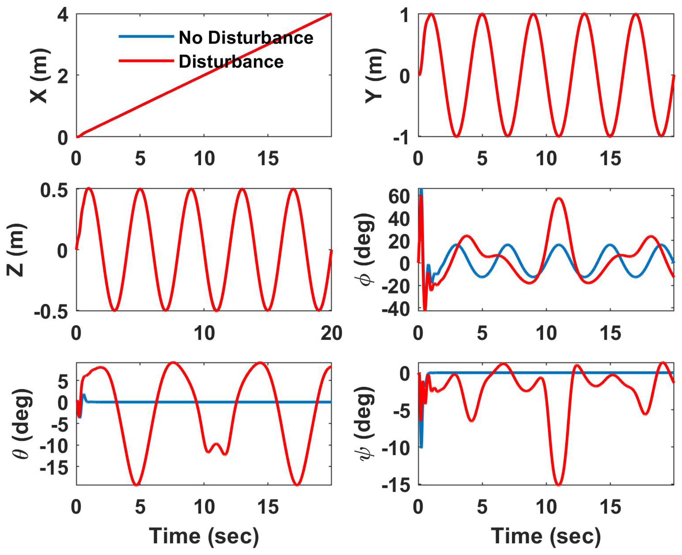
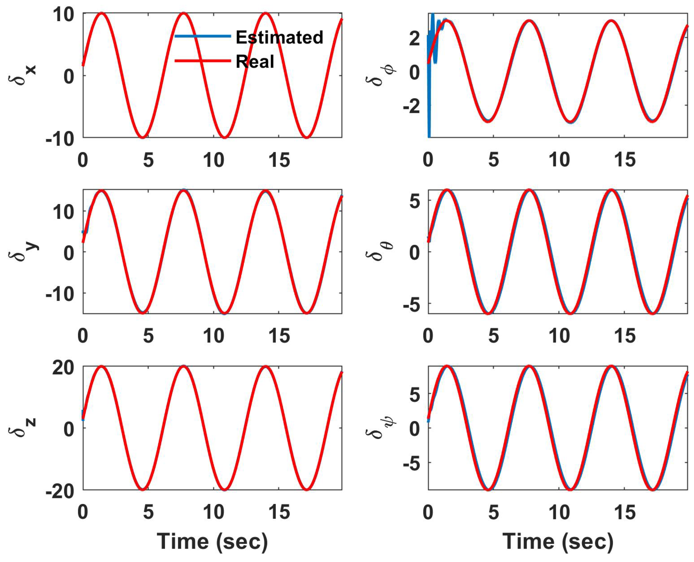
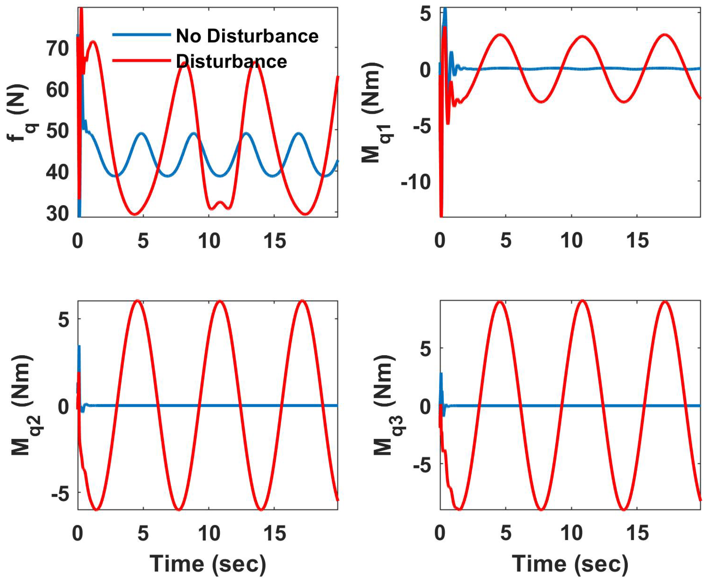
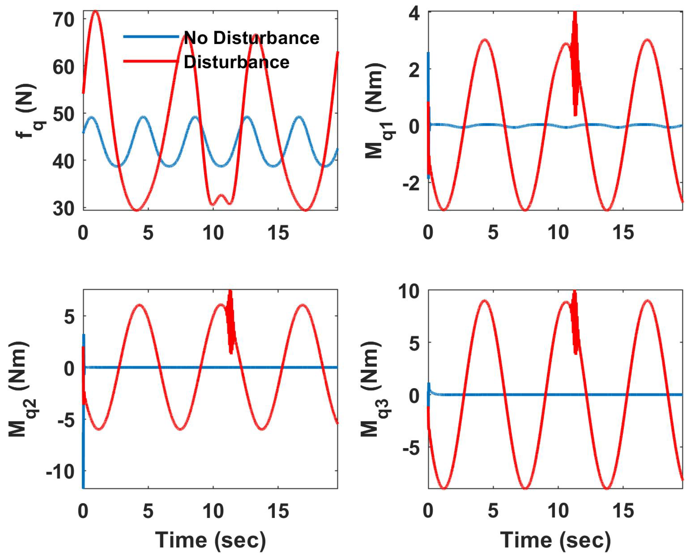
In this case, all the motors are parallel and produce thrust only in the z direction of the body axis. To follow the desired trajectory, the attitude of the UAV is a function of the position control signal. Figure 3, Figure 4 and Figure 5 illustrate the results of the disturbance observer-based controller for UAV control as time-series graphs. Figure 3 compares the states of the UAV in the presence and absence of disturbances and uncertainty. As demonstrated by the simulation results, the UAV is able to follow the desired trajectory, even though its attitude is affected by the disturbance, preventing it from following the desired zero heading angle. The pitch angle oscillates significantly in the presence of an external disturbance, whereas it converges to a constant value in the absence of uncertainty. Furthermore, the roll angle fluctuates more when there is an uncertainty. The mean and standard deviation (SD) between these two cases (ideal vs. disturbed) are presented in Table 1. The mean position error is less than one centimeter, which shows that the UAV can maintain its position despite significant disturbances. However, the mean roll and pitch errors are 13.6 and 8 degrees, respectively, indicating that the attitude of the UAV is more sensitive to external disturbances. Figure 4 illustrates the efficiency of the proposed controller in estimating external disturbances. Figure 5 depicts the UAV control signal, which indicates that the required forces and moments should oscillate to reject sinusoidal external disturbances.
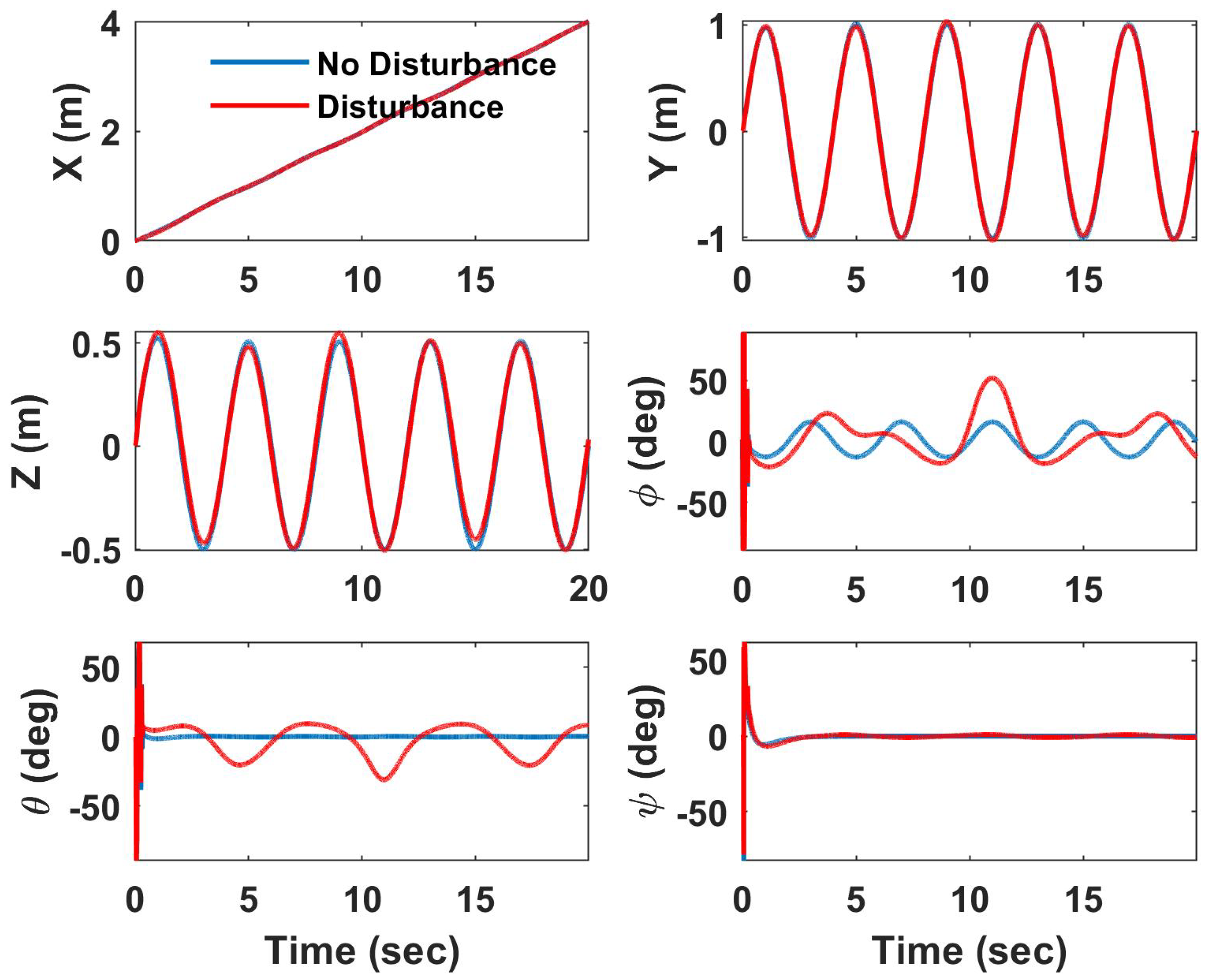
Figure 6 and Figure 7 illustrate the simulation results for the adaptive sliding mode controller in the same scenario as described above. The performance of the position controller is comparable to that of the NDOB (mean error of less than 2 cm, according to Table 2), while the attitude response is less sensitive to external disturbances, and the desired heading angle is maintained. However, considerable initial attitude variation is observed.
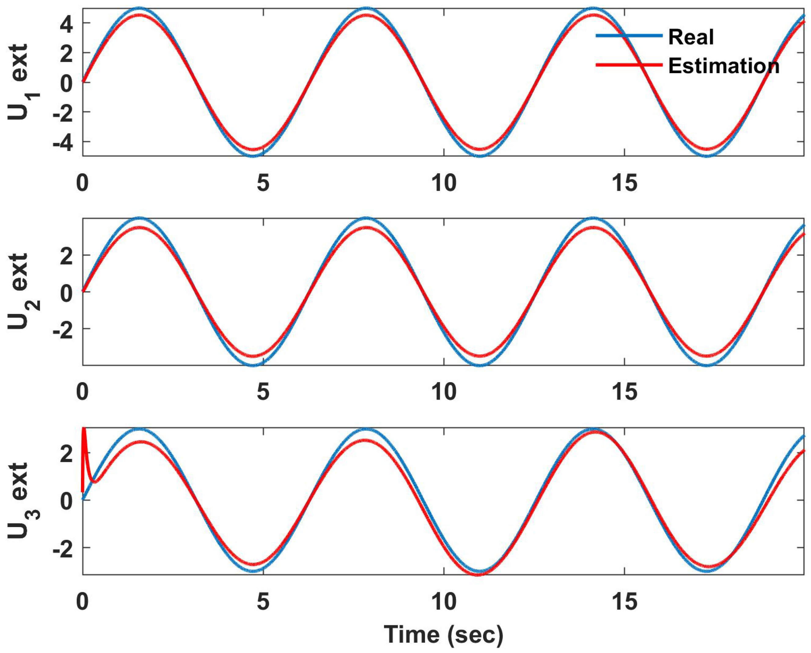
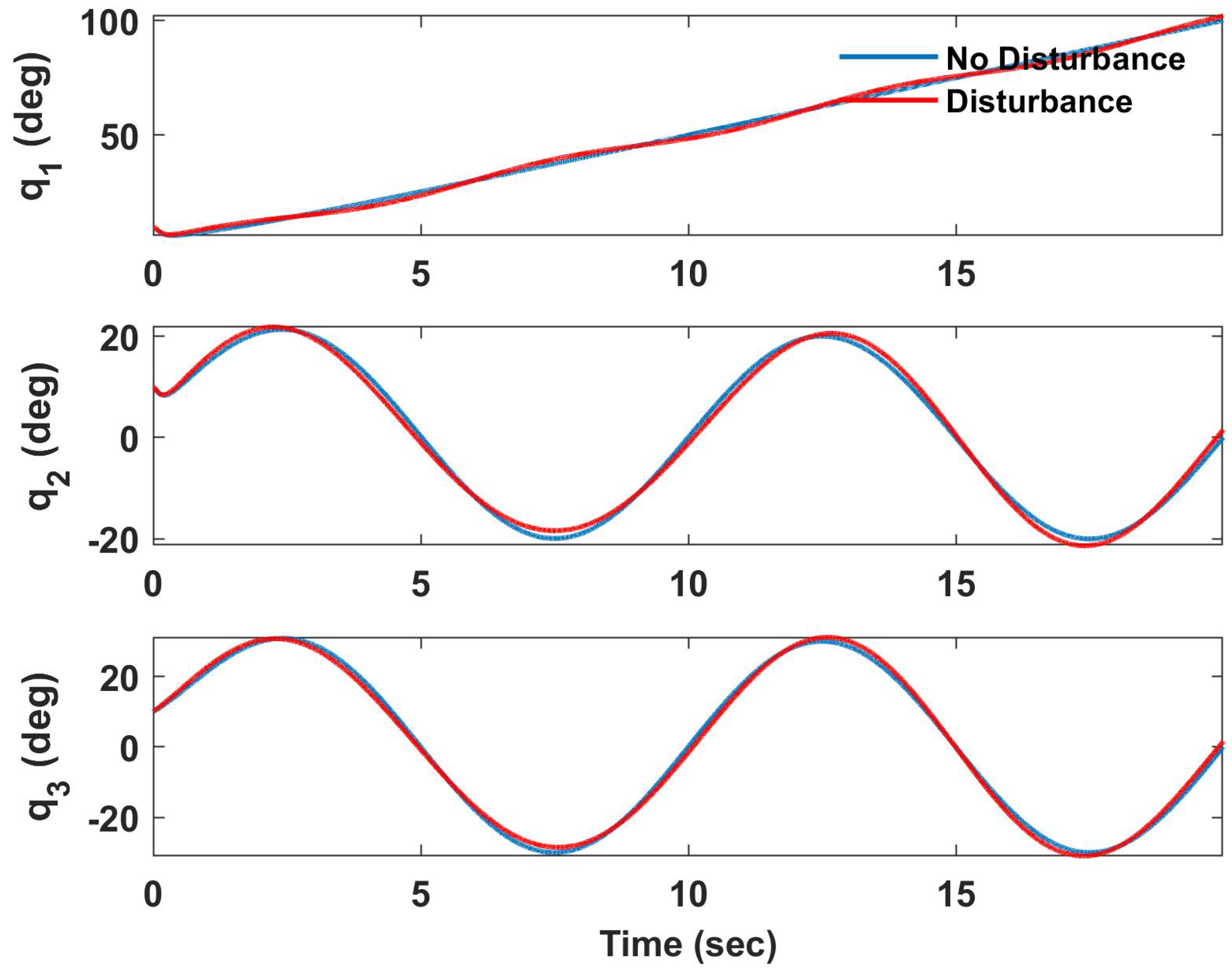
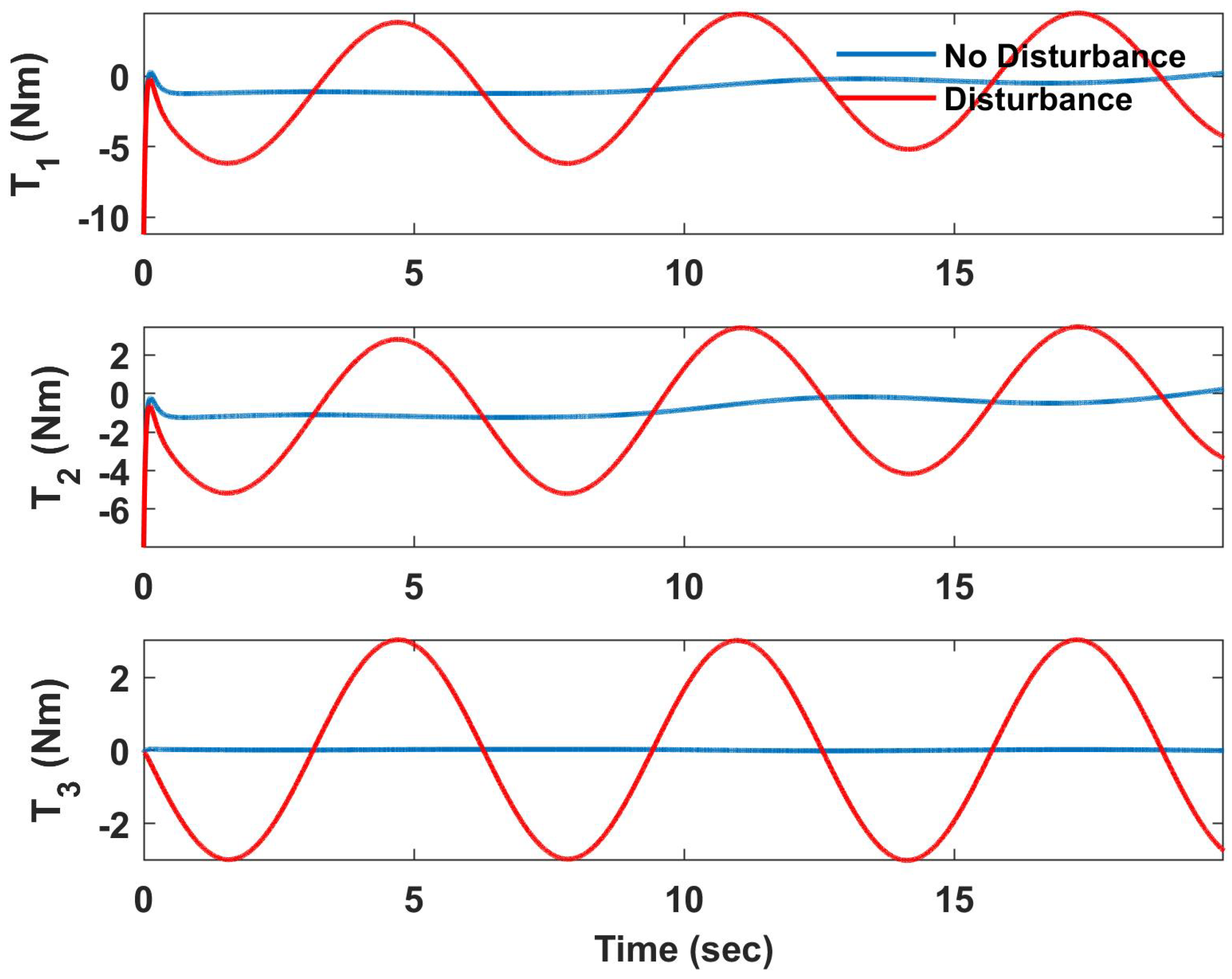
To evaluate the performance of the arm controllers in the presence of severe external disturbances, a sinusoidal disturbance is applied to the dynamics of each joint. The states of the arm for the NDOB controller are shown in Figure 8, revealing that there is not a significant difference between the results in the presence and absence of disturbances (mean error of less than 0.2 deg according to Table 3). Figure 9 and Figure 10 display the control signal and disturbance estimation to demonstrate how the NDOB operates in the presence of disturbances. Figure 11 and Figure 12 exhibit the ASMC results for the same scenario. Compared to the NDOB statistics, the mean joint angle error is greater for ASMC (around 1 degree (Table 4)).
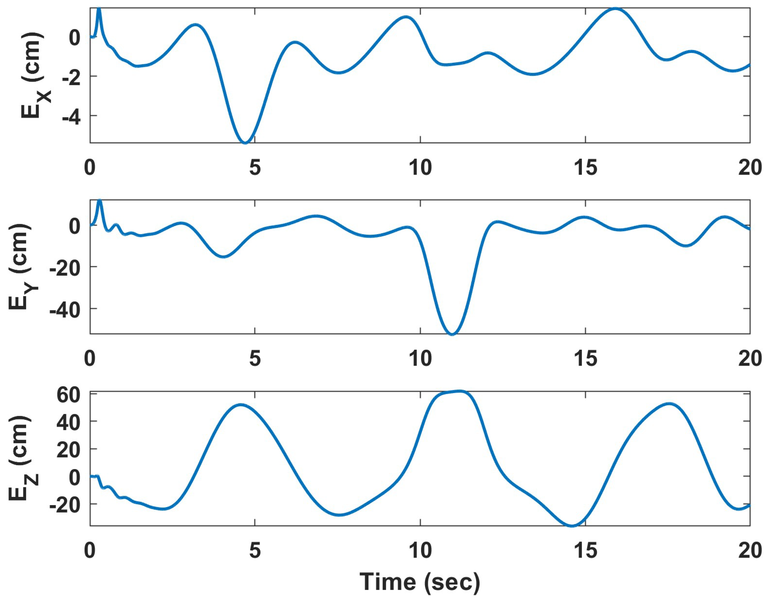
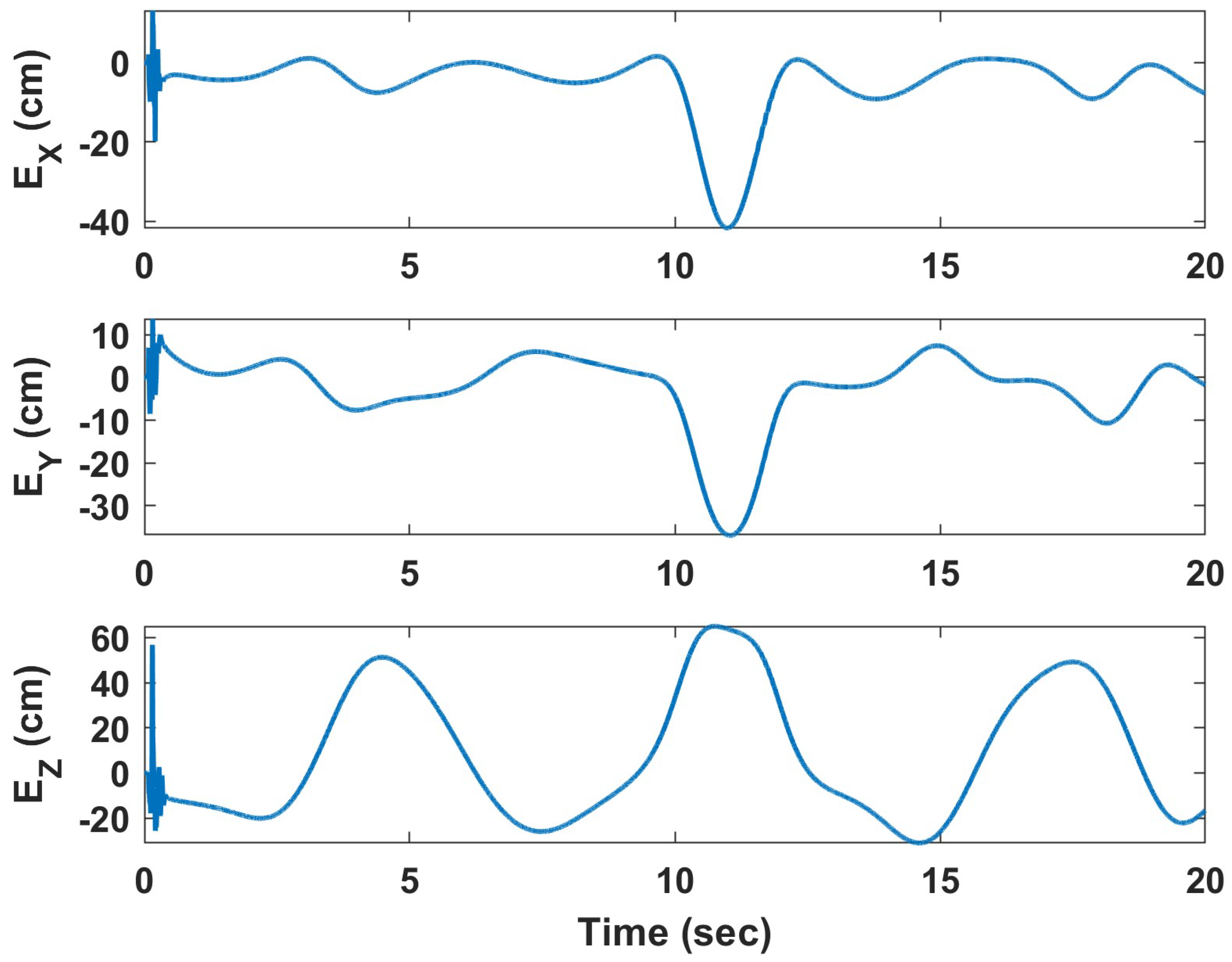
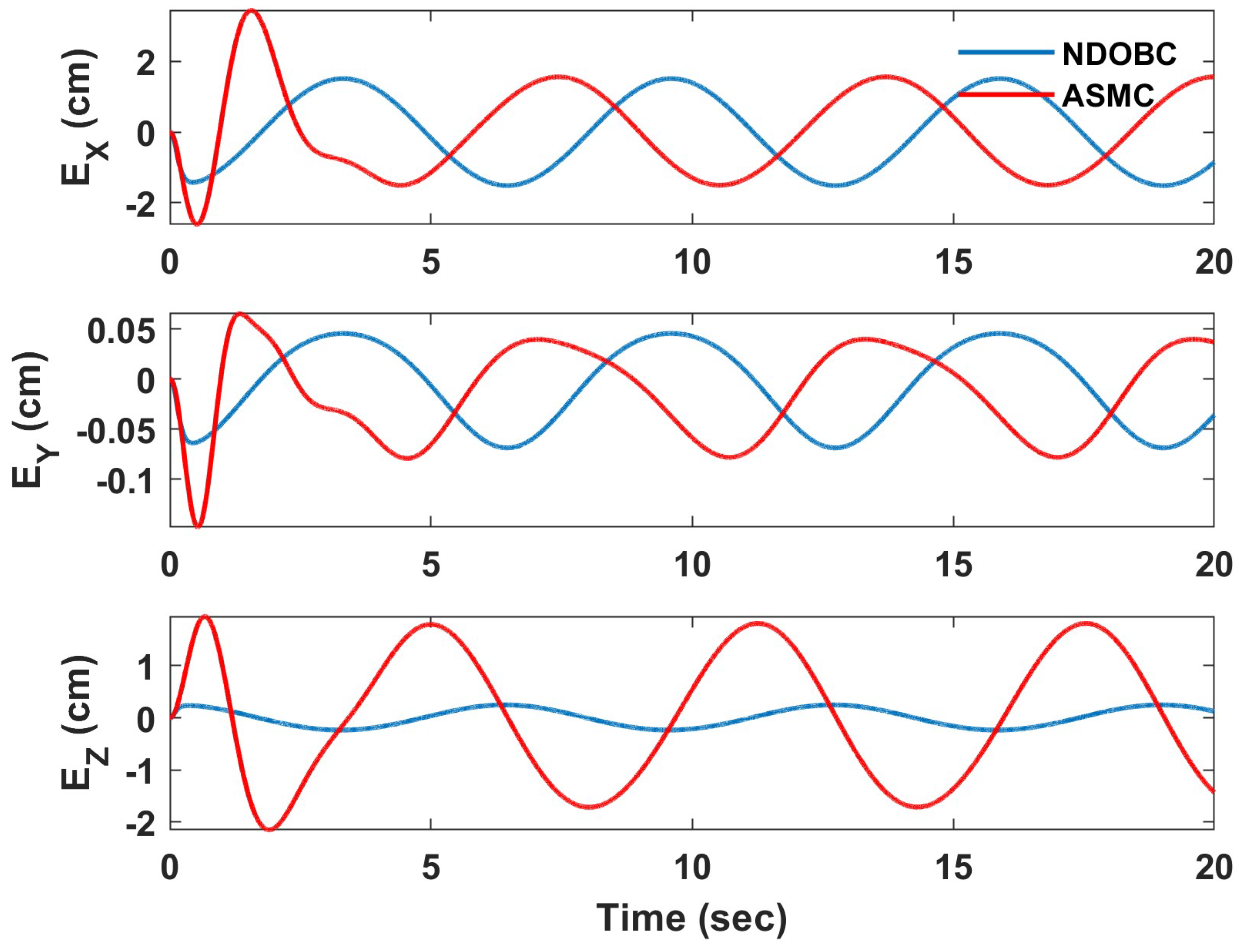
As demonstrated by the findings, both the UAV and the arm controller are capable of completing their tasks in accordance with the desired values. However, plotting the arm’s end-effector position in Figure 13 and Figure 14 reveals that the position of the end effector is significantly affected by external disturbances and uncertainty (about a half-meter inaccuracy, which makes the underactuated UAV an inappropriate platform). This occurs because the UAV attitude must be changed to follow the desired trajectory. In contrast to the ideal case, the end-effector position cannot be maintained. Therefore, it can be concluded that the controller should be designed to control the end effector directly (i.e., using a visual servo controller as a high-level controller to define the desired UAV position and arm angles) or that a fully actuated aerial platform should be considered to allow independent control of the attitude.

4.1.2. Fully Actuated UAV

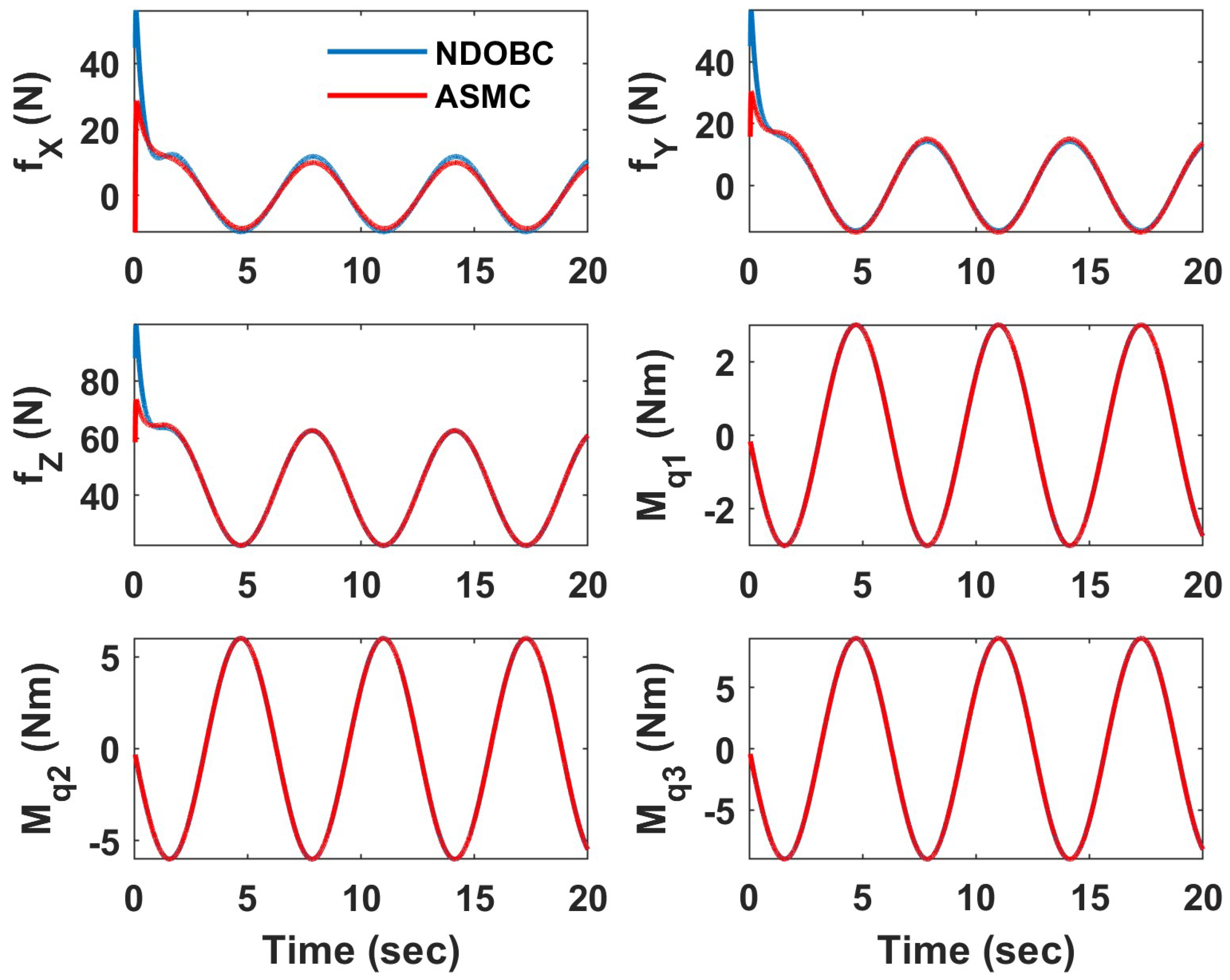
This section considers the identical scenario as the previous section (following a helix trajectory) to demonstrate how efficiently a fully actuated UAV can follow a desired trajectory with zero Euler angles while maintaining the position of the end effector in the presence of considerable external disturbances. For the sake of brevity, the results of NDOBC and ASMC are compared only for the uncertainty scenario (not under ideal conditions). Figure 15 illustrates the UAV states while the control signals are shown in Figure 16. Both NDOBC and ASMC have a comparable performance in the controlling position, but ASMC performs marginally better in maintaining the desired attitude. The control signal for both controllers is nearly identical. The end-effector position is depicted in the time-series graphs in Figure 17, showing that both controllers can keep the end-effector position with an accuracy of 2 cm. The NDOBC performance is marginally better than that of ASMC. The results indicate that both controllers are capable of controlling the UAV while maintaining the position of the end effector.

4.2. Hover Vegetation Sampling Scenario—Fully Actuated UAV

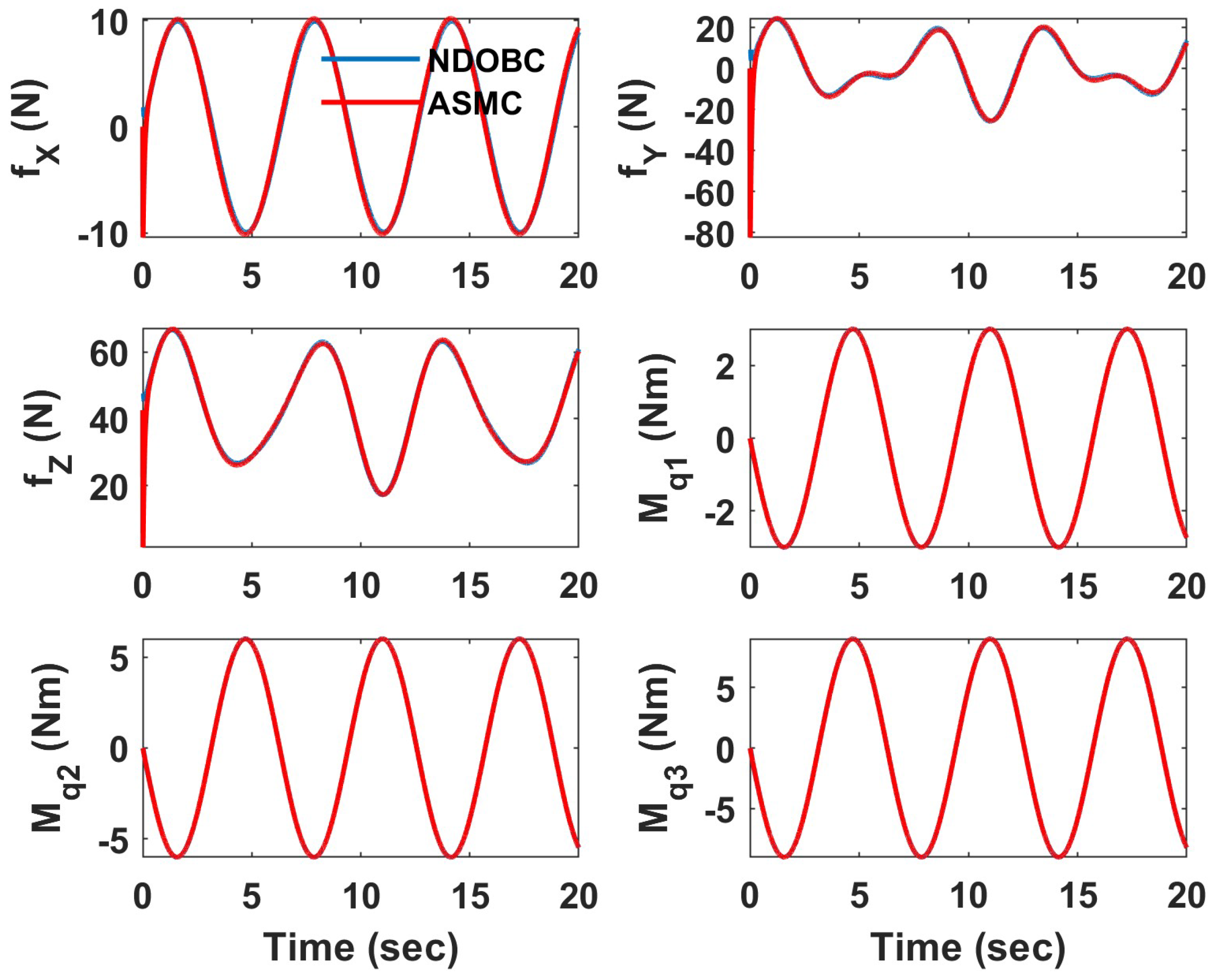
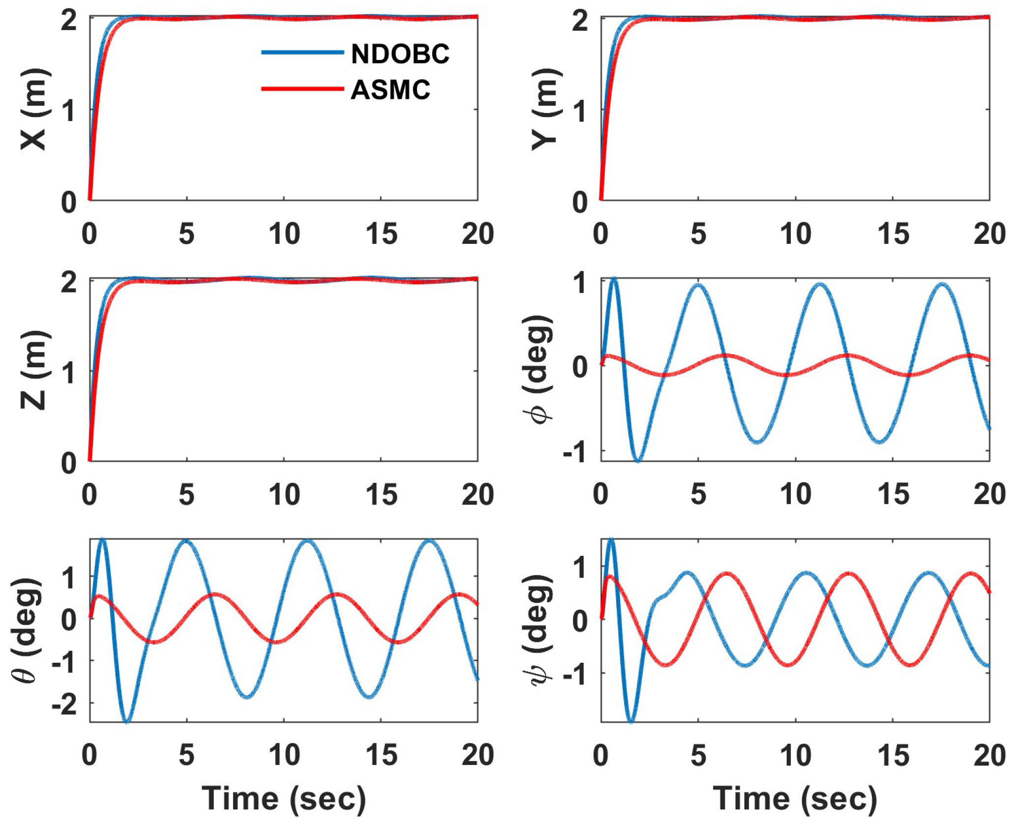
In this scenario, a more realistic instance for sampling vegetation is considered. While cutting tree branches in the real world, the UAV should be able to hover steadily near the tree despite exposure to severe external disturbances, such as wind gusts and external forces and moments resulting from an interaction with the branch. Simultaneously, the end effector should be able to maintain its position to cut the branch and collect a sample. To ensure the success of the aerial sampling mission, it is preferable to pick a fully actuated UAV for the aerial platform, as indicated by the helical trajectory results. Figure 18, Figure 19 and Figure 20 illustrate graphically the outcome of a similar mission in the presence of significant external disturbances. In this instance, the UAV departs from the origin to collect a sample at a location 2 m away from the origin while preserving its end-effector position with respect to the UAV. As demonstrated by the results, the performance and control signals of both controllers are comparable; however, ASMC is more precise in regulating the UAV attitude. The end-effector position error depicted in Figure 20 demonstrates how well a fully actuated aerial vehicle equipped with a robust controller (NDOBC or ASMC) can control the end effector for aerial vegetation sampling in the presence of the most severe possible disturbances.

5. Conclusions and Future Work

In the present work, decoupled nonlinear controllers have been designed and tested in a simulation to control a UAV equipped with an active robotic arm. To achieve a high performance in the presence of uncertainties and external disturbances, nonlinear disturbance observers are added to the control system to estimate the system’s external disturbances. Using the simulation results for both underactuated and fully actuated aerial platforms, the performance and efficiency of the proposed method are demonstrated and compared to an adaptive sliding mode controller. The findings of this study show that both suggested controllers are appropriate for practical scenarios involving the sampling of vegetation using a fully actuated aerial vehicle. The ASMC approach performs somewhat better for UAV control, although an NDOB controller may be a more effective choice for control of the manipulator. Future efforts will concentrate implementing the control schemes on the experimental apparatus and conducting field trials with a physical prototype to validate that the proposed approaches are effective in reducing the effect of disturbances during actual vegetation sampling missions.

Author Contributions

Conceptualization, Z.S. and M.L.; methodology, Z.S. and M.L.; software, Z.S.; validation, Z.S.; formal analysis, Z.S.; investigation, Z.S.; resources, Z.S. and M.L.; data curation, Z.S.; writing—original draft preparation, Z.S.; writing—review and editing, M.L.; visualization, Z.S.; supervision, M.L.; project administration, M.L.; funding acquisition, M.L. All authors have read and agreed to the published version of the manuscript.

Funding

Funding support is gratefully acknowledged from the Natural Sciences and Engineering Research Council of Canada and from the University of Alberta.

Institutional Review Board Statement

Not applicable.

Informed Consent Statement

Not applicable.

Data Availability Statement

Not available.

Acknowledgments

I would like to thank Shayan Meschian for developing the aerial vegetation sampling experimental setup.

Conflicts of Interest

The authors declare no conflict of interest.

Abbreviations

The following abbreviations are used in this manuscript:
AMSAerial Manipulation System
ASMCAdaptive Sliding Mode Control
NNNeural Network
DODisturbance Observer
DOBDisturbance Observer Based
EEEnd Effector
NDOBNonlinear Disturbance Observer
NDOBCNonlinear Disturbance Observer-Based Control
SDStandard Deviation
UAVUnmanned Aerial Vehicle

References

  1. Stolaroff, J.K.; Samaras, C.; O’Neill, E.R.; Lubers, A.; Mitchell, A.S.; Ceperley, D. Energy use and life cycle greenhouse gas emissions of drones for commercial package delivery. Nat. Commun. 2018, 9, 409. [Google Scholar] [CrossRef] [PubMed]
  2. Trujillo, M.Á.; Martínez-de Dios, J.R.; Martín, C.; Viguria, A.; Ollero, A. Novel aerial manipulator for accurate and robust industrial NDT contact inspection: A new tool for the oil and gas inspection industry. Sensors 2019, 19, 1305. [Google Scholar] [CrossRef] [PubMed]
  3. Brescianini, D.; D’Andrea, R. Computationally efficient trajectory generation for fully actuated multirotor vehicles. IEEE Trans. Robot. 2018, 34, 555–571. [Google Scholar] [CrossRef]
  4. Shimahara, S.; Leewiwatwong, S.; Ladig, R.; Shimonomura, K. Aerial torsional manipulation employing multi-rotor flying robot. In Proceedings of the IEEE/RSJ International Conference on Intelligent Robots and Systems (IROS), Daejeon, Republic of Korea, 9–14 October 2016; pp. 1595–1600. [Google Scholar]
  5. Lee, D.; Jang, D.; Seo, H.; Kim, H.J. Model predictive control for an aerial manipulator opening a hinged door. In Proceedings of the 19th International Conference on Control, Automation and Systems (ICCAS), Jeju, Republic of Korea, 15–18 October 2019; pp. 986–991. [Google Scholar]
  6. Thomas, J.; Loianno, G.; Sreenath, K.; Kumar, V. Toward image based visual servoing for aerial grasping and perching. In Proceedings of the IEEE International Conference on Robotics and Automation (ICRA), Hong Kong, China, 31 May–5 June 2014; pp. 2113–2118. [Google Scholar]
  7. Mellinger, D.; Lindsey, Q.; Shomin, M.; Kumar, V. Design, modeling, estimation and control for aerial grasping and manipulation. In Proceedings of the IEEE/RSJ International Conference on Intelligent Robots and Systems, San Francisco, CA, USA, 25–30 September 2011; pp. 2668–2673. [Google Scholar]
  8. Kutia, J.R.; Stol, K.A.; Xu, W. Aerial manipulator interactions with trees for canopy sampling. IEEE ASME Trans. Mechatron. 2018, 23, 1740–1749. [Google Scholar] [CrossRef]
  9. Kutia, J.R.; Stol, K.A.; Xu, W. Initial flight experiments of a canopy sampling aerial manipulato. In Proceedings of the International Conference on Unmanned Aircraft Systems (ICUAS), Arlington, VA, USA, 7–10 June 2016; pp. 1359–1365. [Google Scholar]
  10. Xu, H.; Yang, Z.; Zhou, G.; Liao, L.; Xu, C.; Wu, J.; Zhang, Q.; Zhang, C. A Novel Aerial Manipulator with Front Cutting Effector: Modeling, Control, and Evaluation. Complexity 2021, 2021, 5695681. [Google Scholar] [CrossRef]
  11. Kutia, J.R.; Stol, K.A.; Xu, W. Canopy sampling using an aerial manipulator: A preliminary study. In Proceedings of the International Conference on Unmanned Aircraft Systems (ICUAS), Denver, CO, USA, 9–12 June 2015; pp. 477–484. [Google Scholar]
  12. Busch, C.A.M.; Stol, K.A.; Van der Mark, W. Dynamic tree branch tracking for aerial canopy sampling using stereo vision. Comput. Electron. Agric. 2021, 182, 106007. [Google Scholar] [CrossRef]
  13. Chen, W.; Yang, J.; Guo, L.; Li, S. Disturbance-observer-based control and related methods—An overview. IEEE Trans. Ind. Electron. 2015, 63, 1083–1095. [Google Scholar] [CrossRef]
  14. Samadikhoshkho, Z.; Ghorbani, S.; Janabi-Sharifi, F.; Zareinia, K. Nonlinear control of aerial manipulation systems. Aerosp. Sci. Technol. 2020, 104, 105945. [Google Scholar] [CrossRef]
  15. Caccavale, F.; Giglio, G.; Muscio, G.; Pierri, F. Adaptive control for UAVs equipped with a robotic arm. IFAC Proc. Vol. 2014, 47, 11049–11054. [Google Scholar] [CrossRef]
  16. Yilmaz, E.; Zaki, H.; Unel, M. Nonlinear adaptive control of an aerial manipulation system. In Proceedings of the 18th IEEE European Control Conference (ECC), Naples, Italy, 25–28 June 2019; pp. 3916–3921. [Google Scholar]
  17. Song, X.; Hu, S. Hierarchy-Based Adaptive Generalized Predictive Control for Aerial Grasping of a Quadrotor Manipulator. Science 2019, 24, 451–458. [Google Scholar] [CrossRef]
  18. Pierri, F.; Muscio, G.; Caccavale, F. An adaptive hierarchical control for aerial manipulators. Robotica 2018, 36, 1527–1550. [Google Scholar] [CrossRef]
  19. Siciliano, B.; Sciavicco, L.; Villani, L.; Oriolo, G. Robotics: Modeling, Planning, and Control, 1st ed.; Springer: London, UK, 2009. [Google Scholar]
  20. Lee, T.; Leok, M.; McClamroch, N.H. Nonlinear robust tracking control of a quadrotor UAV on SE (3). Asian J. Control 2013, 15, 391–408. [Google Scholar] [CrossRef] [Green Version]
Figure 1. Block diagram of UAV control (NDOBC) for the underactuated platform.
Drones 07 00110 g001
Figure 2. AMS experimental setup for vegetation sampling.
Drones 07 00110 g002
Figure 3. Underactuated UAV states for NDOBC.
Drones 07 00110 g003
Figure 4. Underactuated UAV disturbance observation.
Drones 07 00110 g004
Figure 5. Underactuated UAV control signal for NDOBC.
Drones 07 00110 g005
Figure 6. Underactuated UAV states for ASMC.
Drones 07 00110 g006
Figure 7. Underactuated UAV control signal for ASMC.
Drones 07 00110 g007
Figure 8. Arm states for NDOB.
Drones 07 00110 g008
Figure 9. Arm control signal for NDOB.
Drones 07 00110 g009
Figure 10. Arm disturbance estimation for NDOB.
Drones 07 00110 g010
Figure 11. Arm states for ASMC.
Drones 07 00110 g011
Figure 12. Arm control signal for ASMC.
Drones 07 00110 g012
Figure 13. Arm’s end-effector position error for NDOBC—underactuated UAV.
Drones 07 00110 g013
Figure 14. Arm’s end-effector position error for ASMC—underactuated UAV.
Drones 07 00110 g014
Figure 15. Fully actuated UAV states.
Drones 07 00110 g015
Figure 16. Fully actuated UAV control signals.
Drones 07 00110 g016
Figure 17. Arm’s end-effector position—fully actuated UAV.
Drones 07 00110 g017
Figure 18. Fully actuated UAV states—vegetation sampling case.
Drones 07 00110 g018
Figure 19. Fully actuated UAV control signals—vegetation sampling case.
Drones 07 00110 g019
Figure 20. Arm’s end-effector position—vegetation sampling case.
Drones 07 00110 g020
Table 1. Mean and standard deviation for NDOBC underactuated UAV control.
x (cm)y (cm)z (cm) ϕ  (deg) θ  (deg) ψ  (deg)
Mean0.1330.4180.13213.6248.0012.683
SD0.1690.5050.20216.1569.1863.528
Table 2. Mean and standard deviation for ASMC underactuated UAV control.
x (cm)y (cm)z (cm) ϕ  (deg) θ  (deg) ψ  (deg)
Mean0.4711.7162.22613.0719.5570.693
SD0.5581.9132.40515.20611.3950.895
Table 3. Mean and standard deviation for NDOBC arm control.
q 1  (deg) q 2  (deg) q 3  (deg)
Mean0.15840.17500.0574
SD0.17660.19500.0650
Table 4. Mean and standard deviation for ASMC arm control.
q 1  (deg) q 2  (deg) q 3  (deg)
Mean0.19180.95281.0383
SD1.33361.06611.1556
Disclaimer/Publisher’s Note: The statements, opinions and data contained in all publications are solely those of the individual author(s) and contributor(s) and not of MDPI and/or the editor(s). MDPI and/or the editor(s) disclaim responsibility for any injury to people or property resulting from any ideas, methods, instructions or products referred to in the content.