Article

A Computational Investigation of the Hover Mechanism of an Innovated Disc-Shaped VTOL UAV

by
Samia Shahrin Ahmed Snikdha
* and
Shih-Hsiung Chen
Department of Aeronautics and Astronautics (DAA), College of Engineering, National Cheng Kung University, No. 1, University Rd, East District, Tainan City 701, Taiwan
*
Author to whom correspondence should be addressed.
Drones 2023, 7(2), 105; https://doi.org/10.3390/drones7020105
Submission received: 22 December 2022 / Revised: 24 January 2023 / Accepted: 31 January 2023 / Published: 3 February 2023

Abstract

:
Inventive approaches are constantly being revealed in the field of vertical take-off and landing (VTOL) unmanned aerial vehicle (UAV) configuration concepts and designs. To date, a body-associated configuration of UAVs for augmented lift remains unclear among other approached designs. The current paper investigates the mechanism of a high-lift ducted fan mounted in the central body for VTOL UAV designs. We report an unresolved design of a disc-shaped UAV with a single rotor that aims to enhance the cost-effectiveness of fuel consumption with a substantial contribution of body lift to hover thrust. The convex upper surface curvature was applied to generate a significant lift contribution from the body during hover. The computational fluid dynamics (CFD) approach based on unstructured discretization followed by three-dimensional steady Reynolds-averaged Navier–Stokes (RANS) flow was applied in ANSYS CFX to mechanistically investigate the underlying design considerations. The disc-shaped UAV uses the lip curvature on the duct inlet to generate a vertical force that demonstrates a significant contribution of 95% of the rotor thrust during hovering. The UAV’s upper surface generates prolonged flow entrainment free from momentum losses in swirling flows. This phenomenon is followed by reduced power consumption in hovering and vertical flight, making the UAV aerodynamically stable and environmentally safe.

1. Introduction

From the beginning of the 21st century, researchers and industries have been coming forward to model the innovative engineering designs of effective flying drones with improved aerodynamic performances and capabilities. A recent review report [1], gave an overview of the types of UAVs and their subsystems and evaluated different applications related to remote sensing, spraying of liquids, and logistics. Another study [2], reported a classification, a broad spectrum of applications, and the existing challenges of UAV designs. Some of the most common applications of flying drones are remote sensing; aerial photography for completing intelligence, surveillance, and reconnaissance missions; environmental protection; mailing and delivery; and other miscellaneous applications.
The rotary wing design of UAVs or drones allows them to fly at high speeds and perform VTOL and hovering flight; however, to date, challenges associated with efficient performance in cruise flight are being faced [3]. Although rotary-wing drones have simple control systems and they are maneuverable, their main disadvantage is power consumption [4,5]. The aerodynamic interactions between multiple rotors, fuselage, and lifting bodies add further complexities. The SUI endurance simulations of forward flight in [6] have provided insight into better designs during cruise; under-mounting the fore rotors and over-mounting the aft rotors improves the aerodynamic efficiency of the vehicle. The hybrid SUI increases the forward horizontal force by 63% compared to the standard SUI. However, even with mild rotor–rotor interactions, the aerodynamic performance of the vehicle is affected, thus requiring design improvements. The authors of [6] conducted a study on the flight phases of the classic commercial quadcopter DJI Phantom and reported that an octa-rotor (coaxial quadrotor) not only increases the thrust but also the power required to fly it. The authors of [7] showed that, at the same power consumption, the thrust is significantly greater than the simple superposition of the thrust generated by the eight small single rotors. However, the power consumption of the rotor is affected by the inward interaction from the rotor wake. The difficulties associated with the rotor–rotor interactions of the quadrotor aircraft were further analyzed by [8] through numerical simulations, both in hover and forward flight. They reported that the inflow caused by interaction between rotors during hover was higher than that of a single rotor; additionally, the tip vortex and downwash flow of the upstream rotors have a strong impact on the downstream rotors during forward flight.
Another appealing branch of multirotor drones is the design of coaxial rotor systems. The authors of [9] reported that there is a peak in the total rotor efficiency (thrust-to-power ratio) for coaxial rotors, and that the efficiency can be increased by 2% to 5% by increasing the pitch of the lower rotor. However, the thrust of a coaxial rotor system is reduced compared to having the rotors in line or having a single octa-rotor.
The aerodynamic behaviors of UAVs make it difficult to demonstrate the maximum efficiency with minimum power consumption. The authors of [10] reported wind tunnel experiments of the small-scale rotor used in multirotor vehicles, in forward flight at various inflow angles. Their investigation pointed out that, at larger angles of attack, an increase in the freestream advance ratio results in a decrease in thrust and power, whereas, at angles of attacks of less than 15°, the thrust and power follow the increasing trend with increasing advance ratios. However, their results did not report ways to compensate the power consumption at high-speed edgewise flows. In this paper, our simpler comprehensive design approached the disadvantage of high-power consumption from the propellers of multirotor flying drones.
Considering all these challenges of rotorcraft designs in respect to energy resource limitations, in this paper, we propose an innovated design of a disc-shaped VTOL UAV concentrating on energy saving due to the upper surface flow speeding up, leading to lower pressure for extra lift other than rotor thrust. The momentum theory of rotors in hover and vertical flight, first addressed by Glauert [11], is applied to evaluate the thrust, as stated in earlier studies [12]. The lifting rotor is mechanized by achieving lift force and thrust force through the momentum change based on the concept of the induced velocity normal to the disc plane. Moreover, the induced velocity in the far wake is twice that at the rotor disc. The body generates a significant portion of hover thrust to reduce the load of the rotor, resulting in less energy consumption along with longer endurance. The design of the body was modulated by applying the concept of the upper surface curvature on the disc-shaped UAV. Such a curvature effect is an important fluid mechanics phenomenon that has not yet been utilized at its full potential and capabilities. Hatton [13] introduced a family of Coanda UAVs named Geoff’s Flying Saucers (GFS), which have a circular canopy as a housing for the propulsion system with an orthogonal arrangement of the Coanda surfaces. Many engineers [14] have applied their own innovative approaches to Coanda-based UAVs, such as the addition of helium chambers and tandem rotor arrangements to extract higher thrust. The proposed innovative design, based on the upper surface curvature, addresses three key design limitations of conventional Coanda UAVs. Firstly, these designs suffer from thrust losses due to radially broadened geometry. The authors of [15] reported this limitation by developing a mathematical model; however, their model used for the flight mechanics of a Coanda UAV could not contribute to the lift in the spanwise direction. Similarly, [16] reported that the radially broadened structure of Coanda UAVs averts the convex surfaces from high lift contribution along the linear spanwise direction. Moreover, another design limitation is the baseplate of the Coanda UAV that generates negative lift due to propeller downwash. The authors of [17] approached the limitation of negative lift generation with an effective thrust reduction of 34 % and 17 % , respectively. However, unlike the previous studies, we approached mitigating the net thrust reduction by considering a suck-in configuration with a spherical flat lower surface and achieved significant improvement in thrust reduction.
Thirdly, another limitation with such VTOL designs is an alternate to high thrust requirement from the propellers while hovering. Based on the hover performance study [18,19] mechanistic investigations on the hover power compensation of quadcopters, hex copters, or octocopters represent an underdeveloped area of research. Considering the precedent studies, we simulated the conditions of UAV body contribution to hover thrust compensation with the ring-wing airfoil concept [20] by inhaling the air at the center of the craft. The authors of [12] approached the hovering by considering a disc-shaped annular-ducted lift fan system with two fans of 36 blades. However, they did not mention the ways to compensate for the high thrust requirement while hovering. Interestingly, [21] achieved a smooth transition to forward flight by tilting the toroidal fuselage of ‘Cypher’, an unmanned aerial vehicle with two coaxial counter-rotating rotors in a ducted fan arrangement. Their study used the cyclic path of the rotors to reduce the excessive pitching moment generation from the inlet-nose flow separation and the drag penalty on the aft part of the shroud. However, it required a considerable amount of power and did not eliminate the drag generation on the trailing side of the rotor.
This paper presents the aerodynamic behavior of a disc-shaped UAV and aims to investigate the feasibility and flyability of this concept in both vertical flight and hover modes. This system aims to present a substitute for a conventional multirotor propeller-based UAVs, with its body ducting the octa-bladed rotor to improve the propulsive efficiency and lower energy consumption. The proposed VTOL UAV design suggests a minimum energy usage (at a lower RPM) with a compensation of thrust contribution from the body during hover.

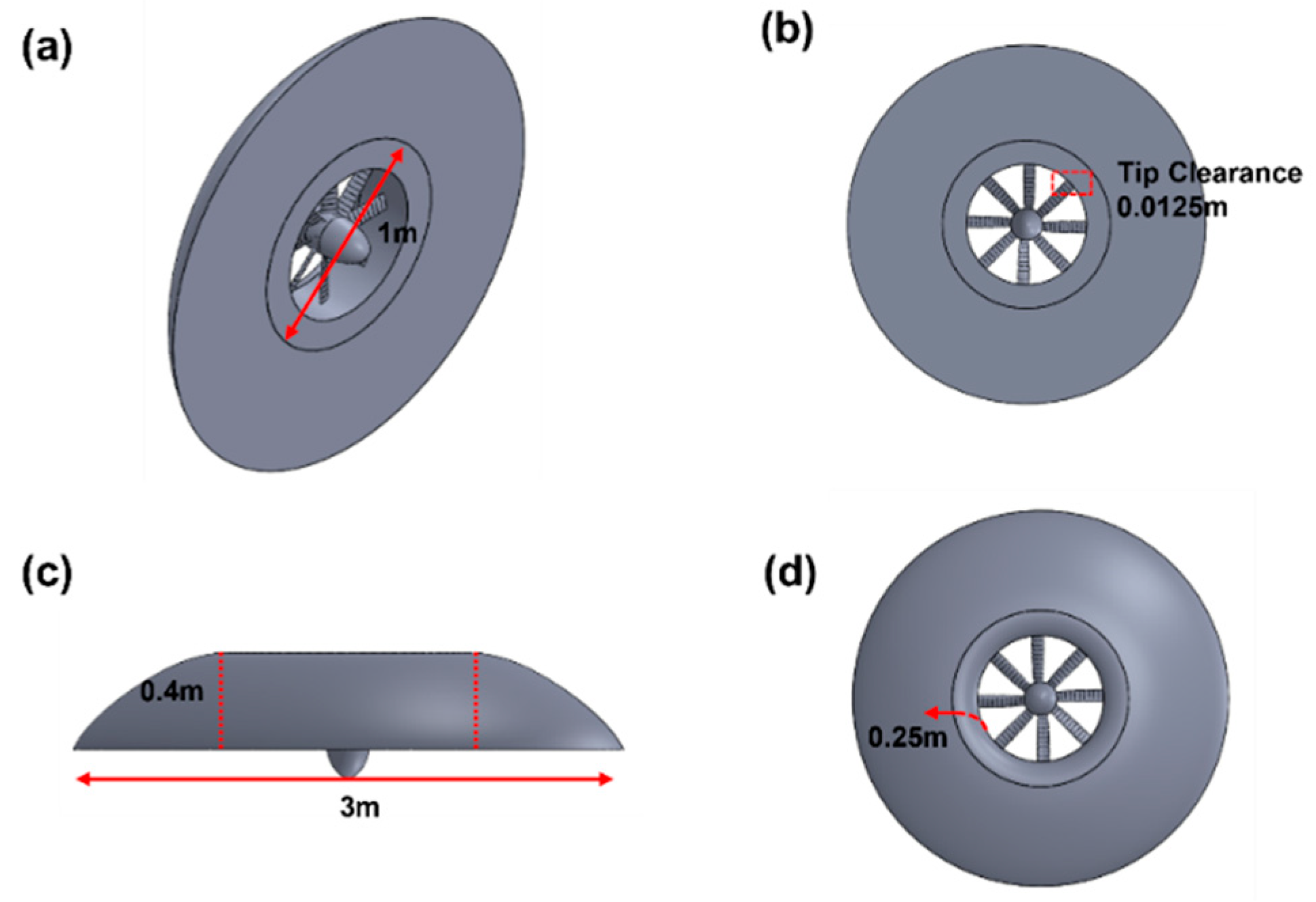
2. The Disc-Shaped VTOL UAV at a Glance

The engineering design software tool Solidworks2018 was used to design the 3D CAD model of the lifting vehicle. We designed the fan blades by considering the NACA 4424 airfoil profile for its satisfactory lift-to-drag ratio. The undertaken drone was a VTOL aircraft with a doughnut shape and a ducted rotor in its center that drove the lifting vehicle. The UAV body diameter equaled 3 m. The simpler comprehensive geometry made the UAV lighter than conventional anuloid UAVs [22]. Both the lift and cruise were generated by a single propulsion system. Figure 1 represents different views of the 3D diagram of the lifting vehicle, with an octa-bladed rotor placed in the inner section of the UAV. The upper surface curvature was designed to apply the lip effect to maintain prolonged flow entrainment during VTOL and the hover mode of the UAV. This geometry belongs to a new class of UAV configuration, where the disc-shaped body essentially makes a significant contribution to the rotor’s thrust.

3. Computational Method

3.1. Mathematical Modeling and Governing Equations

High-fidelity computational fluid dynamics (CFD) simulations are performed to evaluate the aerodynamic characteristics of the vehicle in hover and vertical flight. Fluid dynamic simulations were performed using the general-purpose code [23] ANSYS CFX. The equations that govern the motion of the Newtonian fluid are the continuity, the momentum (Navier–Stokes equations), and the energy equation expressed in terms of surface integrals using Gauss’ divergence theorem over the control volume, V. More often, the solver describes the flow field of the governing equations with the mean values by taking a time-averaged form of the equations known as the Reynolds averaged Navier–Stokes (RANS) equations. With the approach of the eddy viscosity principle after Boussinesq (1877), the general time-averaged RANS equations can be expressed in the tensor form as:
ρ ¯ t + ρ ¯ u i ˜ x i = 0
ρ D U i D t = F i P x j + x j τ i j
where τ i j = μ u i x j + ρ υ T u i x j + u j x i 2 3 κ δ i j corresponds to the total shear stress or the Reynold’s stress.
ρ ¯ E ˜ t + ρ ¯ u ˜ j H ˜ x j = x j q j ¯ ρ u j h ¯ + τ i j u i ¯ ρ u j 1 2 ¯ u i u i + x j τ ¯ i j ρ u i u j ¯
However, the RANS equation requires a turbulence model for its closure in order to approximate the real-world flow field. In this paper, we applied one of the most popular turbulence models, the S S T   k w model developed by Menter. The S S T   k w model is advantageous for its good behavior in adverse pressure gradients and separating flow. The S S T formulation also switches to a k ϵ behavior, developed by Wisconsin, in the freestream and thereby avoids the common k w problem of becoming too sensitive to the inlet freestream turbulence properties. It solves two transport equations, one for the turbulent kinetic energy and one for the turbulent frequency, w .
Turbulent kinetic energy: k t + U j k x j = P k β k ω + x j υ + σ k υ T k x j , where the kinematic eddy viscosity, υ T = a 1 k m a x a 1 ω , S F 2 and P k is the production rate of turbulence. w —equation:
ω t + U j ω x j = a S 2 β w 2 + x j υ + σ ω υ T ω x j + 2 1 F 1 σ ω 2 1 ω k x i ω x i
The closure coefficients and auxiliary relations of the model are given by:
F 2 = tanh m a x 2 k β ω y ,   500 υ y 2 ω 2 ,   P k = m i n τ i j U i x j , 10 β k ω ,
F 1 = tanh m i n m a x k β ω y , 500 υ y 2 ω , 4 σ ω 2 k C D k ω y 2 4 , C D k ω = m a x 2 ρ σ ω 2 1 ω k x i ω x i , 10 10 , φ = φ 1 F 1 + φ 2 1 F 1 , α 1 = 5 9 , α 2 = 0.44 , β 1 = 3 40 , β 2 = 0.0828 , β = 9 100 , α k 1 = 0.85 , α k 2 = 1 , σ ω 1 = 0.5 , and σ ω 2 = 0.856 , where y is the distance to the nearest wall. F 1 = 1 is applied inside the boundary layer and 0 in the free stream. Similarly, F 2 = 1 is applied for the boundary layer flows and 0 for the free shear flows. The structure of the turbulent boundary layer exhibits large velocity gradients and quantities characterizing turbulence rising to a need for near-wall treatment. The finite volume code in the CFX solver implements the wall functions by adding source terms in the momentum equations and by using the log-law, U u τ = 1 k l m E y + , where E = 9.8 is equivalent to the additive constants. Using τ ω = ρ u τ 2 , we obtain τ ω = ρ u τ k U l n E y + . For the wall treatment at the viscous sublayer, the first computational wall is generated with its centroid at y + 1 . This requires a fine mesh adjacent to the wall. However, a higher y + is acceptable as long as it is well inside the viscous sublayer.
The volume and surface integrals of the flow equations are discretized in ICEM CFD by using unstructured mesh. The mesh is then imported to the CFX pre-solver, which utilizes the element-based finite volume method [24] to solve the Navier–Stokes equations, the turbulent kinetic energy, and the turbulent dissipation rate. A fully coupled solver scheme between momentum and pressure equations resolve the pressure–velocity coupling with the second order upwind discretization of the pressure equation.

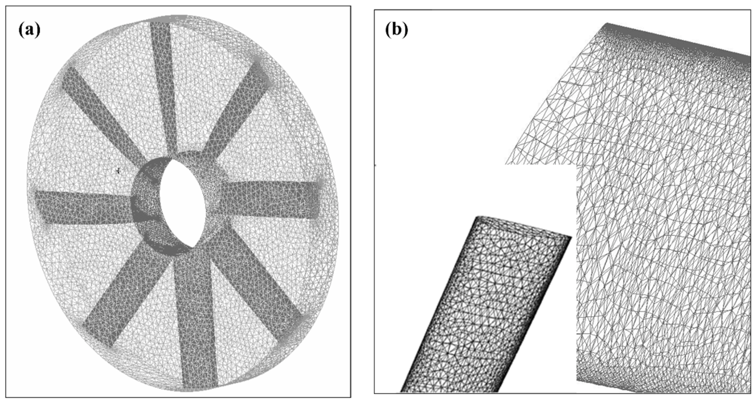
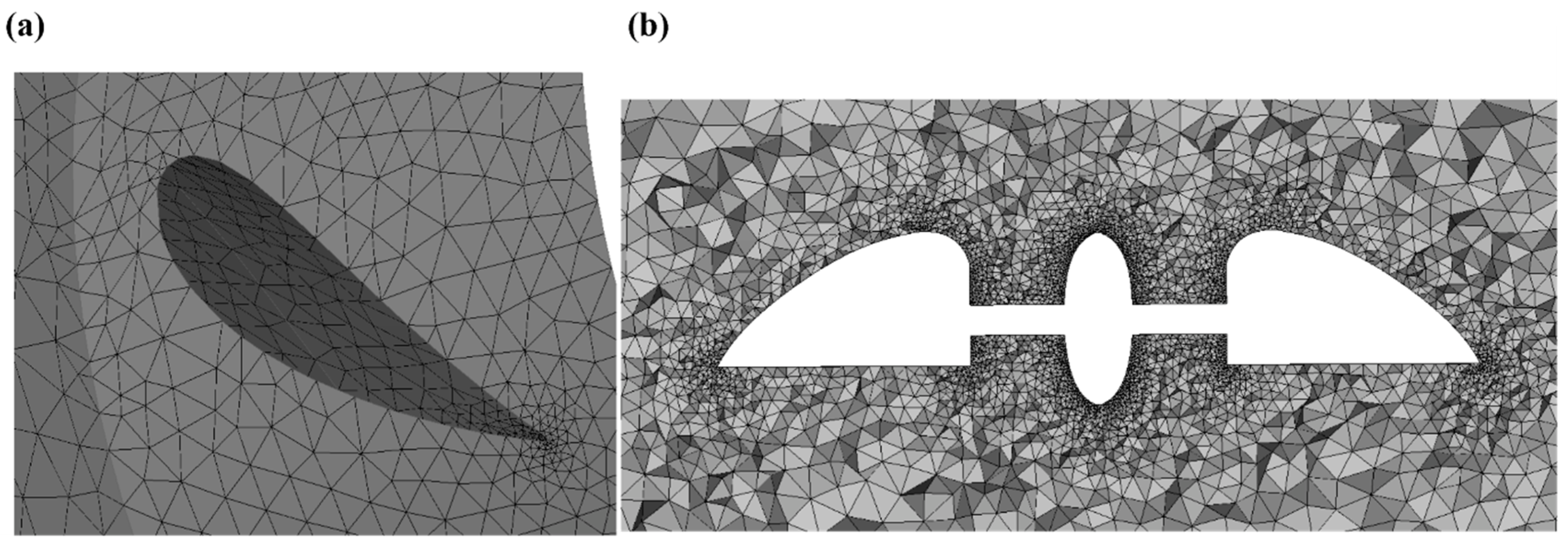
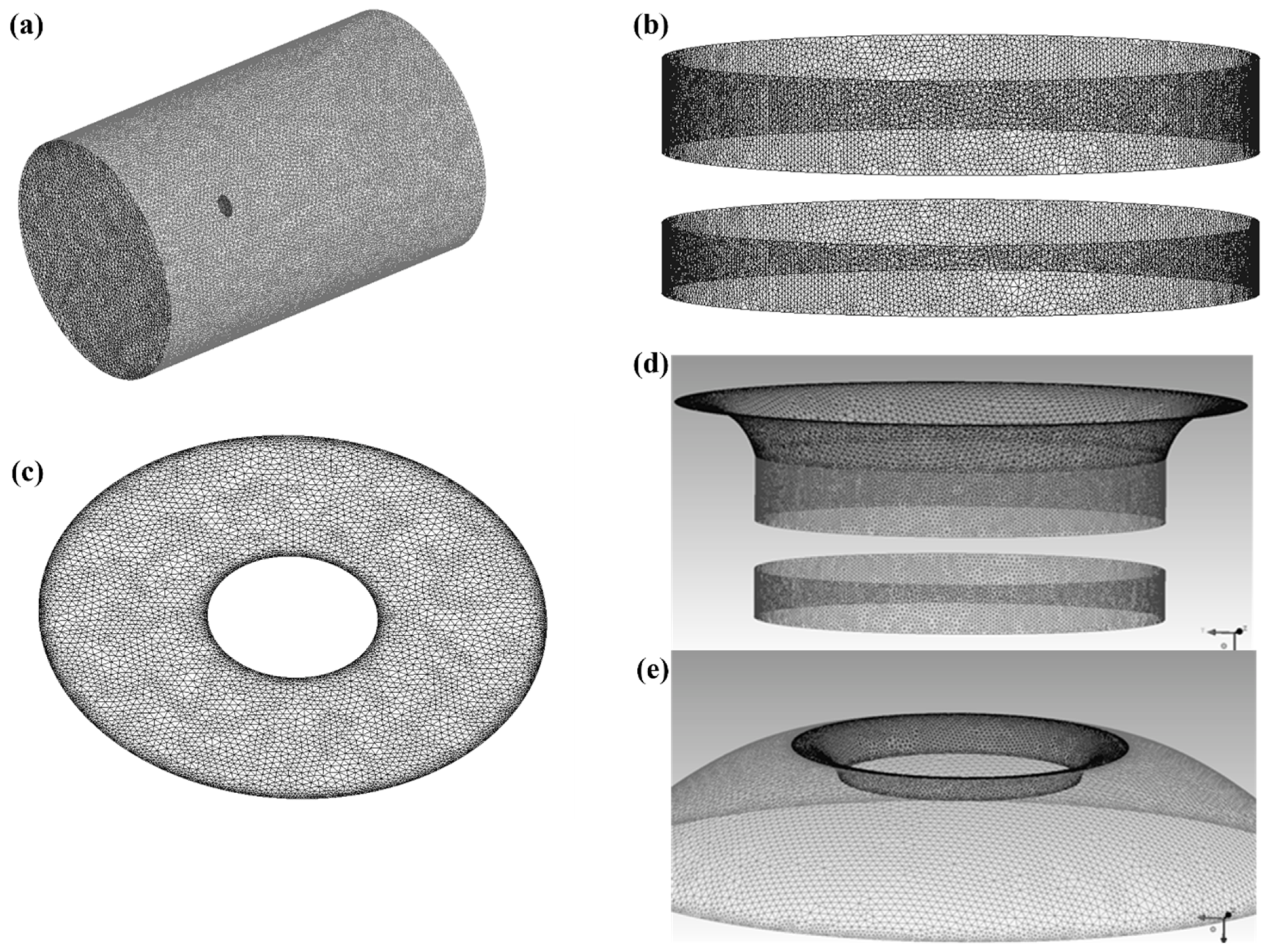
3.2. Generating Computational Mesh

The computational cylindrical domain is a 11D radius measured by a 17D height flow field containing the rotational domain with a height of 120 mm and a radius of 506.25 mm. The UAV in the domains is imported to the widely used commercial software ANSYS ICEM 19.0 for generating the mesh topology. From the experience of many other researchers [25], the unstructured mesh technique is successfully applied to the geometry as depicted in Figure 2 and Figure 3. CFD methods with unstructured grid techniques offer the advantage of handling complex aero geometries with high accuracy results through locally refining the cells as required. Tetrahedral-based volume mesh (Figure 4) is generated by the quick Delaunay method, which provides a fine mesh quality with a smoother transition in the volume element size. The mesh contains 8M cells with 30 prismatic layers in each domain. Previously published reports [26] established high-quality mesh with 20–40 prism layers (each with an expansion ratio of 1.2). The complex flow-oriented zone in the rotational domain contains 5M cells for the sake of solution accuracy. The first layer height of the boundary layer is measured to be 0.006 mm to ensure y + 0.7 on most of the surface area, depending on the freestream velocity in the cruise mode. In CFD modeling, a y + value near unity with a greater number of prism layer elements accurately predicts the flow separation, surface pressure, and aerodynamic forces [27]. Hence, a high resolution of prism mesh is needed to fully resolve the thin boundary layer or the viscous sublayer.

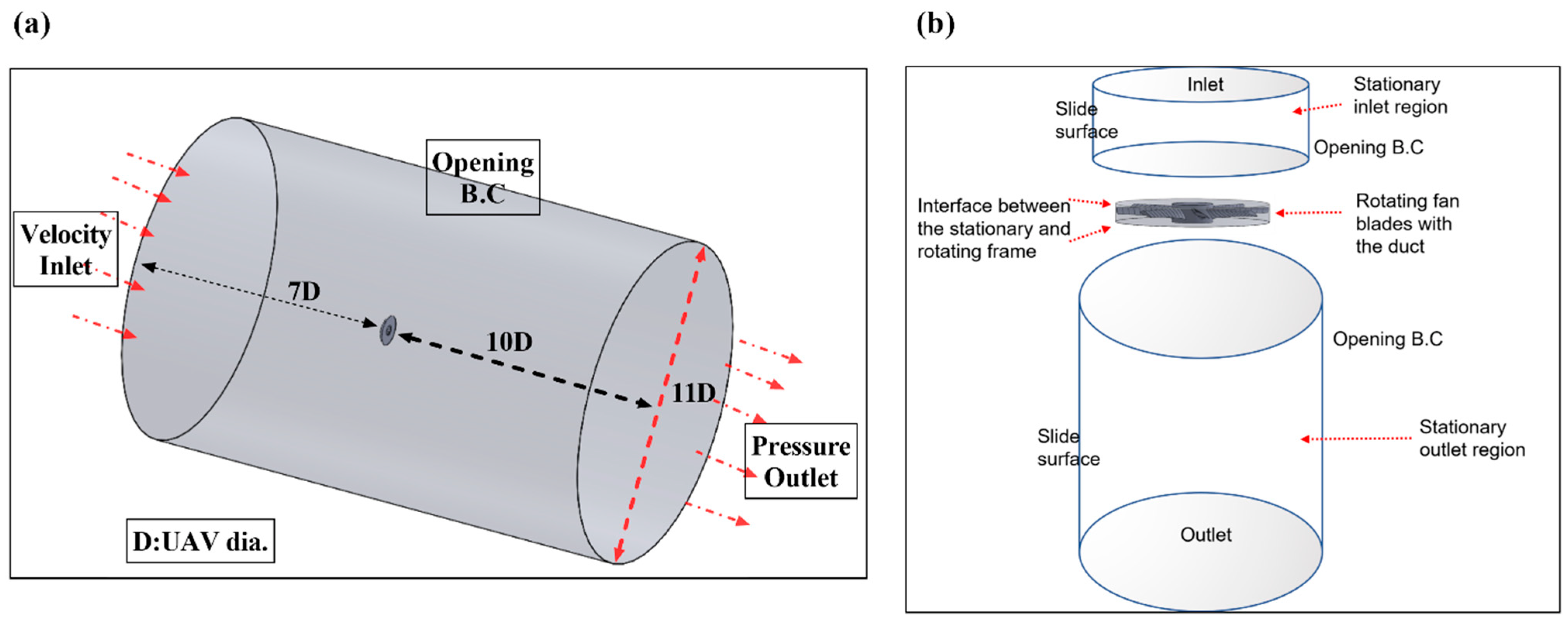
3.3. Boundary Conditions and Physical Modeling

This paper addresses the following features of ANSYS CFX (Table 1). Steady state simulations are carried out in CFX solver with the physical model as explained in Figure 5. For the simulation of the UAV in hover, the computational domain is divided into stationary (inlet and outlet regions) and rotational (rotating fan blades with hub) domains. The steady state physics of the analysis is set up with a velocity inlet (velocity in hover, U = 0 m/s) and pressure outlet definitions. On the side surface, an opening boundary condition is assumed for an opening boundary condition allowing the flow to both enter and leave the fluid domain across the boundary with zero pressure offset during the course of the solution. Air density, dynamic viscosity, and ambient temperature were defined at standard ideal gas states. The solid surfaces of the UAV and the shroud surface of the rotating zone are set as no-slip walls at the adiabatic heat transfer.
For multi-reference domains, the stationary and the rotational reference frames are bridged by an interface connection. A ‘frozen rotor’ type interface model is used in calculations for modeling the frame change with specified pitch angles of 360o on each side. A frozen-rotor interface model can significantly reduce the computational effort and provide reasonably accurate results for steady-state simulations [28,29]. When a frozen rotor is selected, the rotating blades and the body are both frozen, for the actual incoming flow is axisymmetric. Moreover, the attitude of the rotating blades is relative to the rotor and is almost unchanged. With the limited computational effort, the high accuracy and acceptance rate of the frozen rotor model has already been established by many aerodynamics experts [17,18,30]. With this setting, the solid structure of the rotor itself remains fixed; hence, this approach is proposed by many authors [18] due to its reliable accuracy in simulating propeller flow for small-scale multirotor UAVs. The general grid interface (GGI) is used for mesh connections between interfaces. GGI connections refer to gluing the meshes where faces do not match or when a frame change occurs. Menter’s shear stress transport ( S S T ) version of the k ω turbulence model, known for its reliability [31,32,33] and robustness, is applied to solve the boundary layer near the wall surface of the UAV. The zero gradient turbulence model is used for the steady developed flow [34]. Turbulent flows require a heat transfer model for simulation purposes. Accordingly, both the fluid domains were simulated by applying the total energy heat transfer model to characterize the transport of enthalpy, including the kinetic energy effects. The rotating fluid motion was simulated by adding source terms for Coriolis forces and centrifugal forces. Counter-rotating wall velocities were assigned at the shroud surface.

4. Results

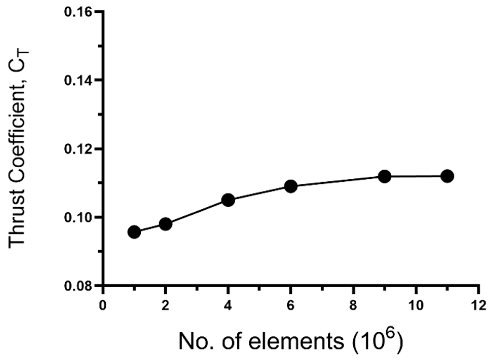
4.1. Mesh Sensitivity Analysis

To validate the computational model, mesh sensitivity analysis was conducted considering the mesh element sizes from coarser to finer. A coarse grid topology with a global maximum element size of 6800 mm for stationary domain parts and 600 mm for rotational parts was selected for the first simulation of the UAV in vertical climb and hovering. The coarse grid topology generates 1M cells. The vehicle thrust coefficient is selected for the mesh independence test parameter. The simulation results led to insignificant results with the coarse grids. However, the thrust coefficient in hover converges to a significant value by refining the mesh elements. The finer mesh is generated by considering global maximum element sizes of 680 mm and 60 mm, respectively, for the stationary and rotational domain parts. Eventually, a negligible discrepancy in the thrust coefficient is achieved with 9M and 11M cells. The thrust coefficient is calculated following the normalized thrust coefficient equation of the momentum theory [35].
Therefore, to reduce the available computational resources, the mesh with 9M cells, containing 5M cells in the rotational domain and 4M cells in the stationery domain, is considered for further investigations in this study. This converged hover thrust coefficient (Figure 6) with a varied number of mesh elements hereby establishes the computational validity of this study.

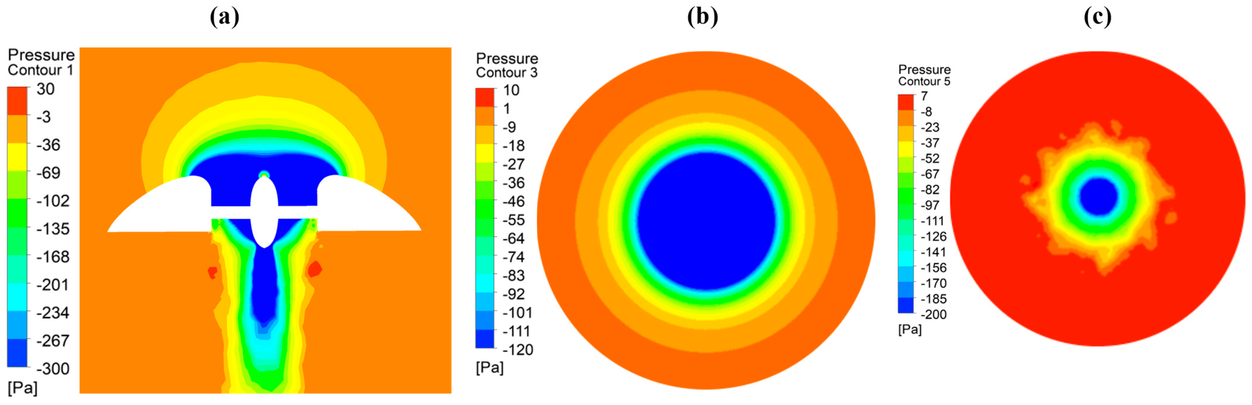
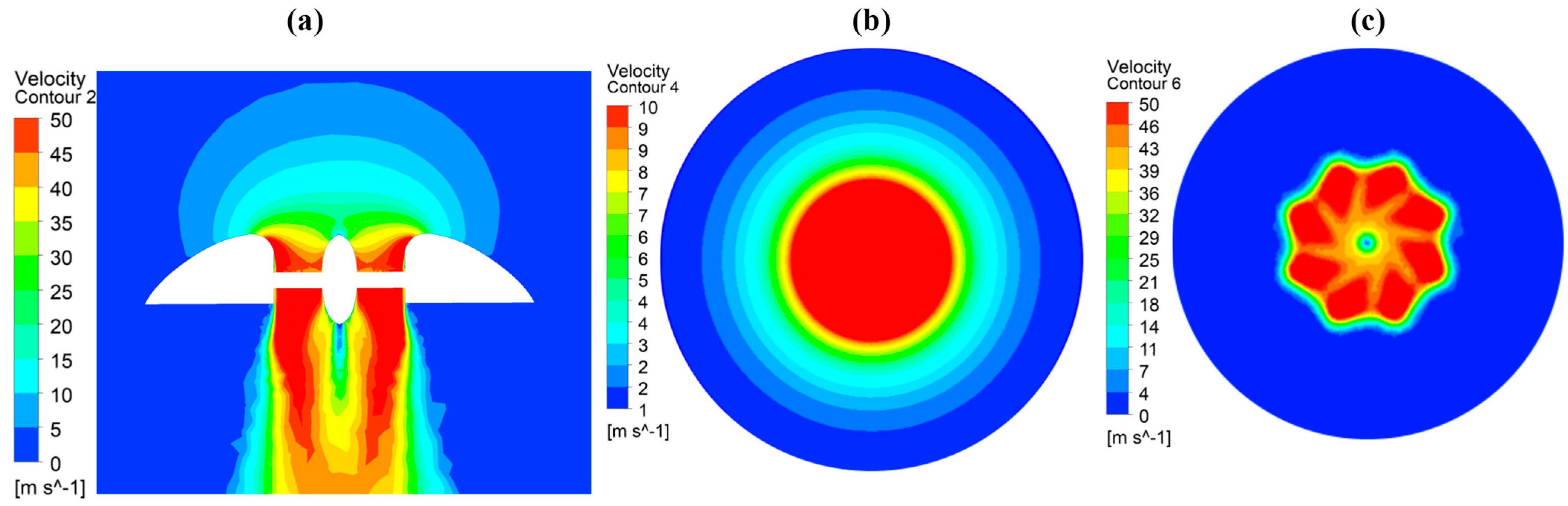
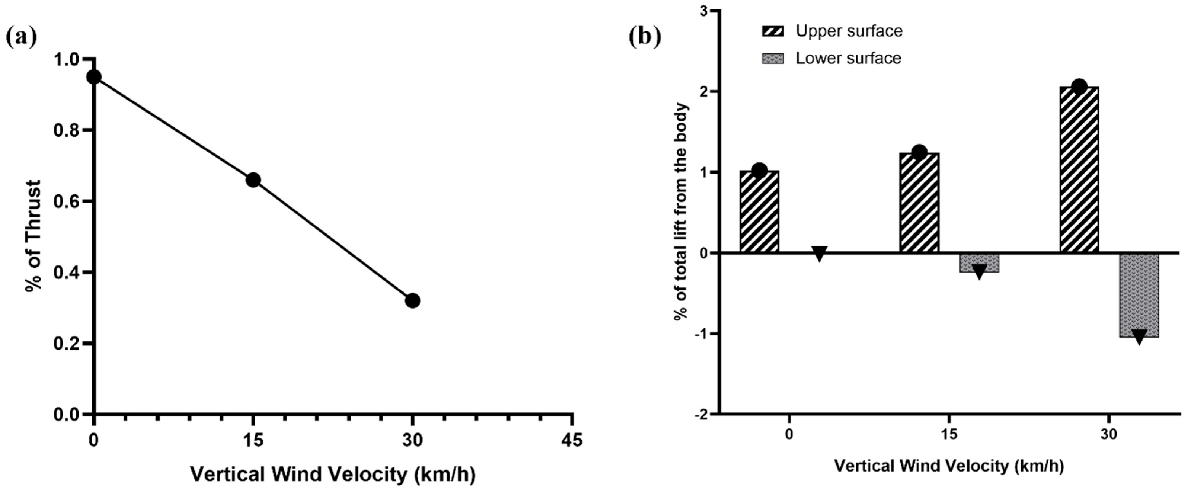
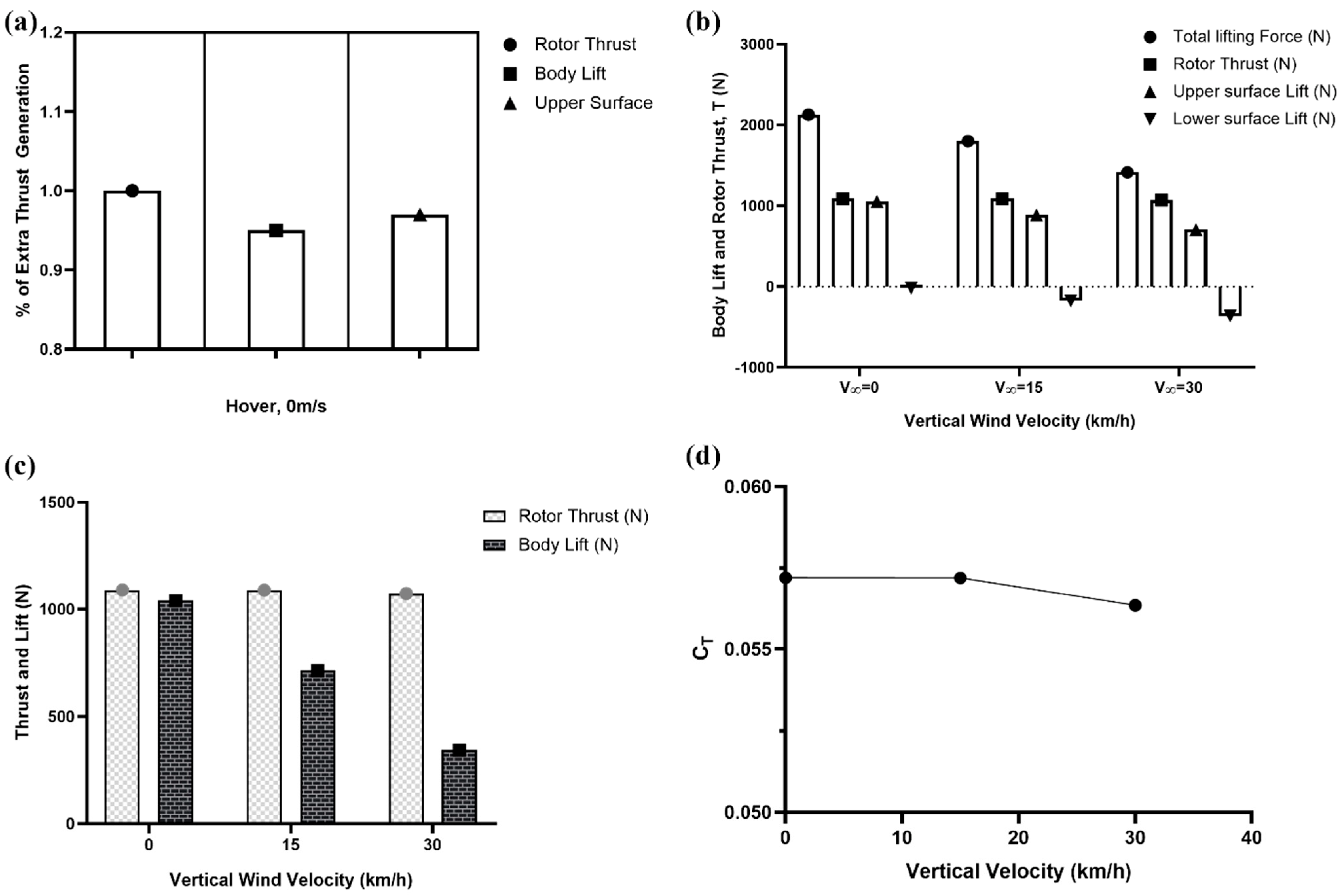
4.2. Hover and Vertical Flight Results

The drone was conceptually designed by combining the upper surface curvature effects and rotor propulsion for lift generation. The CFD tool was applied to validate the physical feasibility of the conceptual design. A curvature on the upper surface of the body and the inlet lip induced a larger and smoother flow into the rotor and created a favorable lower pressure (Figure 7). As the air passes through the rotor following a curved wall, the contact pressure on the curved wall is lower than the ambient pressure because of the presence of viscous phenomena. The shape of such a surface lip plays an important role in improving hover efficiency by generating lower pressure on the contour of the upper surface. Positive pressure arises on the lower surface of the UAV body, adding to the driving pressure gradient and eventually suggesting a high lift contribution from the body. A low-pressure gradient is created on the upper convex lip surface, delineating a high lifting force induced by the curvature effect.
As shown in Figure 8, the air velocity passing over the upper surface of the drone is greater than that passing over the lower surface, leading to higher dynamic pressure on the upper surface compared to the lower surface. In particular, the rotor thrust, and body generated lift acting on the UAV, is increased with the high dynamic pressure, as indicated by the increased velocity gradient on the upper surface. The lower surface velocity profile resembles a star shape formation because of the rotation of the octa-bladed rotor.
The velocity streamlines and the velocity vector plot in Figure 9 indicate a prolonged flow entrainment by the UAV body with stable symmetric flow patterns free from fluid momentum losses in the radial direction. One possible explanation for this innovative design’s efficiency can be observed through the visual interpretation of velocity vector plots. Commonly, conventional saucer-shaped UAVs experience flow separations along the curvature of the upper surface [36]. To study the flow separation mechanism, the velocity vectors are plotted across the central cross-sectional plane, as depicted in Figure 9b, which describes a stable blanket of high velocity air remaining attached to the contours of the upper surface convex curvature without experiencing flow separations. The stability of attached streamlines is achieved at a much lower RPM of 3800 than the investigation of Najafi et al. [37], who observed the stable flow at 8000 RPM on the considered UAV design. The upper body curvature and the spherical disc shape of the UAV account for maintaining attached flow at the aircraft’s trailing edge. However, to study this phenomenon in more detail, future experimental setups would need to provide the ability to visualize the flow separations.
Prolonged flow attachment augments the lift contribution from the body surfaces, which act as a wing to balance the aerodynamic stability of the UAV. As shown in Figure 10a, the upper surface acts as a wing and generates a significantly high lift of 0.96 of rotor thrust. This happens due to the flow speeding up by the convex curvature of the upper surface. However, the lower surface negligibly generates a negative lift of 0.01 of rotor thrust, which reduces the overall body lift by 1%. This negative lift or drag increment, caused by the lower surface due to the rotor downwash, is compensated by the body upper surface. Thus, while hovering, the effective lift from the body alone is 0.95 of the rotor thrust. This significant extra lift from the body augments the hover efficiency compared to the conventional UAVs because the lift contribution from the body makes the vehicle advantageous to the environment for reduced energy consumption. As the vertical wind speed increases, the overall thrust and body lift decreases due to the increasing drag from the lower surface, as shown in Figure 10b,c. During vertical flight, air approaches the UAV at a higher speed, which drags the vehicle towards the fluid flow direction. Thus, the lower surface generates more negative lift at an increasing vertical wind speed. Following the vertical climb theory, keeping a constant RPM, the thrust coefficient of the lifting system decreases with the increasing wind velocity (Figure 10d). This is because, with the increasing inflow speed the angle of attack of the blades decreases and the body contribution becomes less significant due to the force coming from the incoming vertical wind. When the vertical wind speed reaches 15 km/h, the body lift dwindles by 30% of the lift generated in hover mode. This body lift decreases further as the vertical wind speed reaches 30 km/h. Therefore, the specific disc-shaped configuration of the drone body and central position of the fan promoted the lift efficiency due to the low pressure in the upper surface curvature generating a significant thrust contribution from the body.
The simulation results show a hover thrust of 1090 N with a significant contribution from the body lift of 1040 N . Therefore, the generated thrust gives the rotor efficiency η = 111.149 95.05 k g h p = 1.17   kg/hp and the body lift efficiency T P = 106.05 95.05 = 1.12   kg/hp.
The moment on the fan, produced by the aerodynamic force of the rotating blades, is obtained as 215 N m. Thus, the simulated mechanical power of the rotor in hover mode achieved 95.05   hp, which was used to accelerate the air going through the disc area of the rotating rotor. The low power required to run the fan reduces the corresponding drag on the fan blades, resulting in sufficiently less energy consumption. We aimed to design the UAV body to reduce the load on the rotor and then eventually reduce the power consumption. The current multirotor VTOL drones provide hover thrust only by the propellers, with substantial power consumption. In our strategy of a curvature body VTOL UAV, the body shares the lift required to hover by reducing the power consumption of the rotor.
As the UAV starts vertical climbing with the increasing inflow wind speed, the percentage of body lift contribution to the rotor thrust declines. Figure 11a portrays that, while hovering, the body contribution is 0.95 of rotor thrust. As the vertical wind speed reaches 15 km/h, the body lift contribution reduces to 0.66 of rotor thrust, which further decreases to 0.32 of rotor thrust at the wind speed of 30 km/h and constant RPM of 3800. This suggests that the body alone covers a considerable part of hover thrust. The significant portion of the body lift contribution comes from the UAV upper surface due to the curvature configuration. Because the body generates such a significant amount of lift force, unlike conventional multirotor UAVs, this extra lift contributes to the energy-saving potential of the propulsion system, leading to a longer endurance. As shown in the lift distribution of Figure 11b, with the increasing wind speed in vertical flight, the upper surface induces a higher percentage of lift out of the total lift. However, it associates an increasing negative lift from the lower surface. The increasing wind force accounts for the rising drag of the lower surface. To approach the vertical windspeed of 30 km/h at a null incidence with constant RPM, a negative lift of 1.05 of total body lift is generated by the lower surface; nevertheless, this is compensated by the upper surface. The increasing downwash-induced velocity accounts for rising negative lift from the lower surface. The extra lift from the body accelerates the UAV to move vertically upwards toward the wind.
The specific UAV design can save energy due to the following facts: (1) The elimination of rotor wake swirling loss and wake coning loss. The duct associated body eliminates the fan blade tip vortex and prevents the downstream flow from contraction. (2) The substantial amount of extra lift generated by the body as a significant contribution to the rotor thrust. (3) The additional body lift helps to reduce the corresponding power required to operate the UAV and increase the flight endurance. The CFD results of hovering showed that 0.95 of rotor thrust comes from the upper surface curvature lift. Moreover, a negligible drag or negative lift of 0.01 of the total thrust comes from the lower base surface.

5. Discussion

As the new design has demonstrated an effective hover and vertical flight performance with a significant lift contribution from the body, the next stage of the study would be comprised of conducting forward flight simulations. Presumably, in forward flight, the body would play the role of a wing to reduce the load on the rotor. This is because the disc-shaped body would act as a cross-section of the airfoil to generate more lift in forward flight. We attempted to address the reduction in the overall net lift due to the disc-shaped lower surface of the UAV in hover and vertical flight. Figure 11 exhibits a 1 % reduction in the overall net lift generated from the body while hovering at 0 m/s. This reduction percentage due to the flat lower surface is much less than body-associated UAVs with concave or convex lower surfaces, as presented by Nauddin’s UAV in [17], where a 34% body lift reduction was obtained. Furthermore, Barlow et al.’s [20] application of a ring-wing airfoil on a radial UAV generated less than favorable results. However, the application of a ring-shaped upper surface in our inventive design achieved more than favorable results due to the recovery of thrust losses in the radial direction. The duct enclosing the rotor acts as the anti-noise material, resembling Shin et al.’s [38] observations of a reduced acoustic signature of UAV.
The surface streamlines and velocity vector plots depict an interesting behavior of flow attachment, complying with an annular disc of earlier studies [12]. However, inconsistent with the previous study, we considered the upper surface in our geometry, which acts as the wing for the UAV. Generally, the aerodynamic challenges include flow separation from the wings. Nevertheless, our results show highly improved flow separation and swirling flows of the surface streamlines. This ensures reduced thrust losses with efficient energy consumption by the control systems and increases the aerodynamic performance of the UAV and proves to be of a greater potential interest to the industry.
One possible explanation for the innovated design’s efficiency can be observed through the visual interference of velocity vector plots. In conventional saucer-shaped UAVs, flow separations along the convex surface are a common occurrence [36]. Many designers have used vortex generators and axial vanes to prevent or delay flow separations such that the flow remains attached to the curved surface [39]. Researchers in their investigations experienced flow separation characterized by a swirling vortex generated above the upper surface. However, our velocity vector plots show a stable blanket of high velocity attached to the contours of the convex upper surfaces and the flat lower surface without experiencing flow separations.

6. Conclusions

The aerodynamic characteristics of the disc-shaped lifting system for VTOL UAV from vertical climb to hover were investigated by applying the ANSYS CFX software. A significant lift contribution to the hover thrust was generated by the UAV body, with a negligible negative lift caused by the disc-shaped flat lower surface due to rotor downwash. This study proves the concept that the drone body can produce significant extra lift to the rotor, reducing the load on the rotor, both in vertical flight and in hover. This is caused by the pressure differential along the UAV body surfaces, particularly by the flow passing through the upper surface before entering the rotor and creating large negative pressure to lift up the vehicle. In addition to a substantial hover thrust, 95% of the rotor thrust is generated by the UAV body as an extra lift.
For an efficient design along with the energy resource limitations, an alternative lift of the UAV can be generated from the body. The drone body alone generated 0.95 of hover thrust, which significantly contributes to the energy-saving potential of the propulsion system. Thus, the innovative disc-shaped vehicle could eventually lead to longer endurance, which is a common limitation of multirotor UAVs. Additionally, in forward flight the body would play the role of a wing to reduce the load of the rotor to be studied in future. This would result in substantially reduced energy consumption in forward flight.
In future work, the model will be validated for transition to horizontal flight with control approaches to improve the stability of the control system. The predicted simulation data provide useful insights for future experimental studies of the disc-shaped UAV. The unique disc-shaped UAV has high lift efficiency and acceptable lift, generating characteristics of the body with great potential for future VTOL transportation.

Author Contributions

The current research presented in this paper was conceptualized and supervised by S.-H.C.; throughout the methodology the simulations were conducted, and the results were analyzed by S.S.A.S.; data analysis, writing—original draft preparation, S.S.A.S. All authors have read and agreed to the published version of the manuscript.

Funding

This research received no external funding.

Data Availability Statement

The data presented in this study are available on request from the corresponding author.

Conflicts of Interest

The authors declare no conflict of interest.

References

  1. González-Jorge, H.; Martínez-Sánchez, J.; Bueno, M.; Arias, P. Unmanned Aerial Systems for Civil Applications: A Review. Drones 2017, 1, 2. [Google Scholar] [CrossRef]
  2. Hassanalian, M.; Abdelkefi, A. Classifications, applications, and design challenges of drones: A review. Prog. Aerosp. Sci. 2017, 91, 99–131. [Google Scholar] [CrossRef]
  3. Austin, R. Unmanned Aircraft Systems: UAVS Design, Development and Deployment; John Wiley & Sons: Hoboken, NJ, USA, 2011; Volume 54. [Google Scholar]
  4. Aleksandrov, D.; Penkov, I. Energy Consumption of Mini UAV Helicopters with Different Number of Rotors. In Proceedings of the 11th International Symposium” Topical Problems in the Field of Electrical and Power Engineering, Estonia, Pärnu, 16–21 January 2012; pp. 259–262. [Google Scholar]
  5. Bouabdallah, S.; Murrieri, P.; Siegwart, R. Towards Autonomous Indoor Micro VTOL. Auton. Robot. 2005, 18, 171–183. [Google Scholar] [CrossRef]
  6. Diaz, P.V.; Yoon, S. Computational Analysis of Urban Air Mobility Vehicles. In Proceedings of the 8th European Conference for Aeronautics and Aerospace Sciences (EUCASS), NASA Ames Research Center, Moffett Field, Santa Clara, CA, USA, 1–4 July 2019; p. 359. [Google Scholar]
  7. Lei, Y.; Huang, Y.; Wang, H. Aerodynamic Performance of an Octorotor SUAV with Different Rotor Spacing in Hover. Processes 2020, 8, 1364. [Google Scholar] [CrossRef]
  8. Hwang, J.Y.; Jung, M.K.; Kwon, O.J. Numerical Study of Aerodynamic Performance of a Multirotor Unmanned-Aerial-Vehicle Configuration. J. Aircr. 2015, 52, 839–846. [Google Scholar] [CrossRef]
  9. Giljarhus, K.E.T.; Porcarelli, A.; Apeland, J. Investigation of Rotor Efficiency with Varying Rotor Pitch Angle for a Coaxial Drone. Drones 2022, 6, 91. [Google Scholar] [CrossRef]
  10. Kolaei, A.; Barcelos, D.; Bramesfeld, G. Experimental Analysis of a Small-Scale Rotor at Various Inflow Angles. Int. J. Aerosp. Eng. 2018, 2018, 1–14. [Google Scholar] [CrossRef]
  11. Byham, G.M. The future of rotorcraft. Aeronaut. J. -New Ser. 2003, 107, 377–388. [Google Scholar] [CrossRef]
  12. Jiang, Y.; Zhang, B.; Huang, T. CFD Study of an Annular-Ducted Fan Lift System for VTOL Aircraft. Aerospace 2015, 2, 555–580. [Google Scholar] [CrossRef]
  13. Hatton, G. Thrust Generating Apparatus. US0213090A1, 4 September 2008. [Google Scholar]
  14. Nedelcut, F. Coanda Effect UAV—A New Born Baby in the Unmanned Aerial Vehicles Family. Rev. Air Force Acad. 2010, 17, 21–28. [Google Scholar]
  15. Ahmed, R.I.; Abu Talib, A.R.; Rafie, A.S.M.; Djojodihardjo, H. Aerodynamics and flight mechanics of MAV based on Coandă effect. Aerosp. Sci. Technol. 2017, 62, 136–147. [Google Scholar] [CrossRef]
  16. Hibbeler, R. Fluid Mechanics, 2nd ed.; Pearson: London, UK, 2015. [Google Scholar]
  17. Siddiqi, Z.; Lee, J.W. Experimental and numerical study of novel Coanda-based unmanned aerial vehicle. J. Eng. Appl. Sci. 2022, 69, 76. [Google Scholar] [CrossRef]
  18. Lopez, O.D.; Escobar, J.A.; Pérez, A.M. Computational Study of the Wake of a Quadcopter Propeller in Hover. In Proceedings of the 23rd AIAA Computational Fluid Dynamics Conference, Denver, Colorado, 5–9 June 2017. [Google Scholar] [CrossRef]
  19. Henricks, Q.; Wang, Z.; Zhuang, M. Small-Scale Rotor Design Variables and Their Effects on Aerodynamic and Aeroacoustic Performance of a Hovering Rotor. J. Fluids Eng. 2020, 142, 081209. [Google Scholar] [CrossRef]
  20. Barlow, C.; Lewis, D.; Prior, S.D.; Odedra, S.; Erbil, M.A.; Karamanoğlu, M.; Collins, R. Investigating the Use of the Coanda Effect to Create Novel Unmanned Aerial Vehicles. In Proceedings of the International Conference on Manufacturing and Engineering Systems, Huwei, Yunlin, Taiwan, 17–19 December 2009; pp. 386–391. [Google Scholar]
  21. Cycon, J.P.; Scott, M.W.; DeWitt, C.W. Method of Reducing a Nose-Up Pitching Moment on a Ducted Unmanned Aerial Vehicle. US6170778B1, 9 January 2001. [Google Scholar]
  22. Petrolo, M.; Carrera, E.; D'Ottavio, M.; Visser, C.C.d.; Pátek, Z.; Janda, Z. On the development of the Anuloid, a disk-shaped VTOL aircraft for urban areas. Adv. Aircr. Spacecr. Sci. 2014, 1, 353–378. [Google Scholar] [CrossRef]
  23. Stajuda, M.; Karczewski, M.; Obidowski, D.; Jóźwik, K. Development of a CFD model for propeller simulation. Mech. Mech. Eng. 2016, 20, 579–593. [Google Scholar]
  24. van Leer, B. Towards the ultimate conservative difference scheme. V. A second-order sequel to Godunov's method. J. Comput. Phys. 1979, 32, 101–136. [Google Scholar] [CrossRef]
  25. Xu, H.; Ye, Z.-Y.; Shi, A.-M. Numerical Study of Propeller Slipstream Based on Unstructured Dynamic Overset Grids. J. Aircr. 2012, 49, 384–389. [Google Scholar] [CrossRef]
  26. Ryu, M.; Cho, L.; Cho, J. Aerodynamic Analysis of the Ducted Fan for a VTOL UAV in Crosswinds. Trans. Jpn. Soc. Aeronaut. Space Sci. 2016, 59, 47–55. [Google Scholar] [CrossRef]
  27. Blocken, B.; Defraeye, T.; Koninckx, E.; Carmeliet, J.; Hespel, P. CFD simulations of the aerodynamic drag of two drafting cyclists. Comput. Fluids 2013, 71, 435–445. [Google Scholar] [CrossRef]
  28. Kim, W.-Y.; Senguttuvan, S.; Kim, S.-M. Effect of Rotor Spacing and Duct Diffusion Angle on the Aerodynamic Performances of a Counter-Rotating Ducted Fan in Hover Mode. Processes 2020, 8, 1338. [Google Scholar] [CrossRef]
  29. Thouault, N.; Breitsamter, C.; Adams, N.A. Numerical and Experimental Analysis of a Generic Fan-in-Wing Configuration. J. Aircr. 2009, 46, 656–666. [Google Scholar] [CrossRef]
  30. Kutty, H.A.; Rajendran, P. 3D CFD Simulation and Experimental Validation of Small APC Slow Flyer Propeller Blade. Aerospace 2017, 4, 10. [Google Scholar] [CrossRef]
  31. Pérez Gordillo, A.M.; Villegas Santos, J.S.; Lopez Mejia, O.D.; Suárez Collazos, L.J.; Escobar, J.A. Numerical and Experimental Estimation of the Efficiency of a Quadcopter Rotor Operating at Hover. Energies 2019, 12, 261. [Google Scholar]
  32. Jiang, Y.; Zhang, B. Numerical Investigation of Effect of Parameters on Hovering Efficiency of an Annular Lift Fan Aircraft. Aerospace 2016, 3, 35. [Google Scholar] [CrossRef]
  33. Min, K.-M.M.K.-M.; Tjprc. Design and CFD Analysis of A Low-Altitude VTOL UAV. Int. J. Mech. Prod. Eng. Res. Dev. (IJMPERD) 2019, 9, 555–562. [Google Scholar]
  34. Prisacariu, V. CFD Analysis of UAV Flying Wing. Incas Bull. 2016, 8, 65–72. [Google Scholar] [CrossRef]
  35. John Seddon, S.N. Rotor in Vertical Flight: Momentum Theory and Wake Analysis. In Basic Helicopter Aerodynamics; John Wiley & Sons: Hoboken, NJ, USA, 2011; pp. 23–61. [Google Scholar] [CrossRef]
  36. Crivoi, O.; Doroftei, I. Some experimental results on Coanda effect with application to a flying vehicle. IOP Conf. Ser. Mater. Sci. Eng. 2016, 147, 012082. [Google Scholar] [CrossRef]
  37. Najafi, M.; Jahanmiri, M. An Innovative Technique to Increase Lift of a Coanda UAV. IOSR J. Mech. Civ. Eng. 2017, 14, 27–35. [Google Scholar] [CrossRef]
  38. Shin, D.; Kim, H.; Gong, J.; Jeong, U.; Jo, Y.; Matson, E.T. Stealth UAV through Coandă Effect. In Proceedings of the 2020 Fourth IEEE International Conference on Robotic Computing (IRC), Taichung, Taiwan, 9–11 November 2020; pp. 202–209. [Google Scholar]
  39. Gad-el-Hak, M.; Bushnell, D. Separation Control: Review. J. Fluids Eng. 1991, 113, 5–30. [Google Scholar] [CrossRef]
Figure 1. Design parameters of the lifting UAV; (a) isometric view, (b) bottom view, (c) side view, and (d) top view.
Drones 07 00105 g001
Figure 2. (a) Surface mesh on the UAV body inside the stationary domain, (b) duct, (c) lower surface, (d) lip curvature, and (e) upper surface.
Drones 07 00105 g002
Figure 3. (a) Surface mesh on the UAV parts in the rotating domain, (b) zoomed-in view of the mesh on the blades.
Drones 07 00105 g003
Figure 4. (a) Hub showing the blade section, (b) volume mesh through the mid-section of the UAV in the density zone.
Drones 07 00105 g004
Figure 5. (a) Computational domain interpreting boundary conditions; (b) interface between the rotational and stationary domains.
Drones 07 00105 g005
Figure 6. Mesh sensitivity analysis in hovering.
Drones 07 00105 g006
Figure 7. Pressure contour at hovering, U = 0   m / s . (a) XY, Z = 0 mid-plane, (b) YZ, X = −0.5 upper surface, and (c) YZ, X = 0.5 lower surface cross-sectional plane.
Drones 07 00105 g007
Figure 8. Velocity contour at hovering, U = 0   m / s . (a) XY, Z = 0 mid-plane, (b) YZ, X = −0.5 upper surface, and (c) YZ, X = 0.5 lower surface cross-sectional plane.
Drones 07 00105 g008
Figure 9. Mid-section plane plots of (a) surface streamlines, and (b) velocity vector in hovering, at U = 0 m/s.
Drones 07 00105 g009
Figure 10. (a) Extra lift contribution from the body delineating the UAV hover efficiency, (b) discrete hover and vertical flight thrust with body lift, (c) percentage generation of body lift and rotor thrust in hover and vertical flight, and (d) thrust coefficient of the UAV with increasing vertical wind speed.
Drones 07 00105 g010
Figure 11. (a) The percentage of extra lift generated by the body compared to the rotor thrust, (b) lift distribution of the body from hover with 0 m/s to the vertical flight with increasing wind velocity.
Drones 07 00105 g011
Table 1. Physical modeling in CFX.
ComponentFeatureDetails
ANSYS CFX—PreSimulation typeSteady state
Fluid typeAir ideal gas
Domain typeMultiple domain
Rotating frame of reference
Stationery frame of reference
Turbulence modelSST
Heat transferTotal energy
Boundary conditionsVelocity inlet (Subsonic)
Pressure outlet (Subsonic)
Wall: no-slip
Wall: adiabatic
Far-field: opening
Domain interfacesGeneral connection
Frozen rotor
Specified pitch angles (360o)
TimestepPhysical timescale: 0.1 ω
ANSYS CFX—Solver ManagerStartDouble Precision
ANSYS CFX—PostPlotsContour: pressure, and velocity
Streamlines
Velocity vector
Disclaimer/Publisher’s Note: The statements, opinions and data contained in all publications are solely those of the individual author(s) and contributor(s) and not of MDPI and/or the editor(s). MDPI and/or the editor(s) disclaim responsibility for any injury to people or property resulting from any ideas, methods, instructions or products referred to in the content.

