


A Review of Icing Research and Development of Icing Mitigation Techniques for Fixed-Wing UAVs

Abstract
:1. Introduction
2. Methods of Studying Ice Accretion on a UAV
2.1. Experimental Studies
2.1.1. Flight Tests
2.1.2. Lab Tests
2.2. Numerical Studies
2.2.1. Validation of Existing Simulation Tools
2.2.2. Developing of New Models
3. Advances in UAV Icing Research
3.1. Typical Icing Characteristics of UAVs
3.2. Changes in Aerodynamic Characteristics Caused by Icing
4. Existing Anti-Icing/Deicing Techniques for UAVs
5. Exploring Ice Mitigation Techniques for UAVs
5.1. Airfoil Optimization
5.2. Flight Optimization
5.3. Coatings
5.4. Electric Heating for Anti-Icing/Deicing
5.4.1. Selection of High-Quality Materials
5.4.2. Search for Cost-Effective Manufacturing Processes
5.4.3. Design of System Layout
5.4.4. Combining with Coatings
5.5. Piezoelectric Deicing
5.6. Plasma Anti-Icing/Deicing
5.7. Synthetic Thermal Jet for Anti-Icing/Deicing
6. Discussions
7. Conclusions
Author Contributions
Funding
Data Availability Statement
Conflicts of Interest
Appendix A

| Researchers | Year | Research Method | Major Achievement or Key Findings |
|---|---|---|---|
| Bottyán et al. [15] | 2013 | Flight tests | A UAV ice accretion model was developed. |
| Williams et al. [16] | 2017 | Flight tests and lab tests | The ice shapes differed significantly from those on high Reynolds number airfoils. |
| Matiychyk et al. [17] | 2017 | Flight tests | The energy consumption of unmanned aerial vehicles increased after icing. |
| Siddique [19] | 2021 | Flight tests | |
| Han et al. [20] | 2023 | Flight tests | |
| Avery [18] | 2019 | Flight tests | The geometric shape of ice driven by the flight flow field appeared on the surface of the drone. |
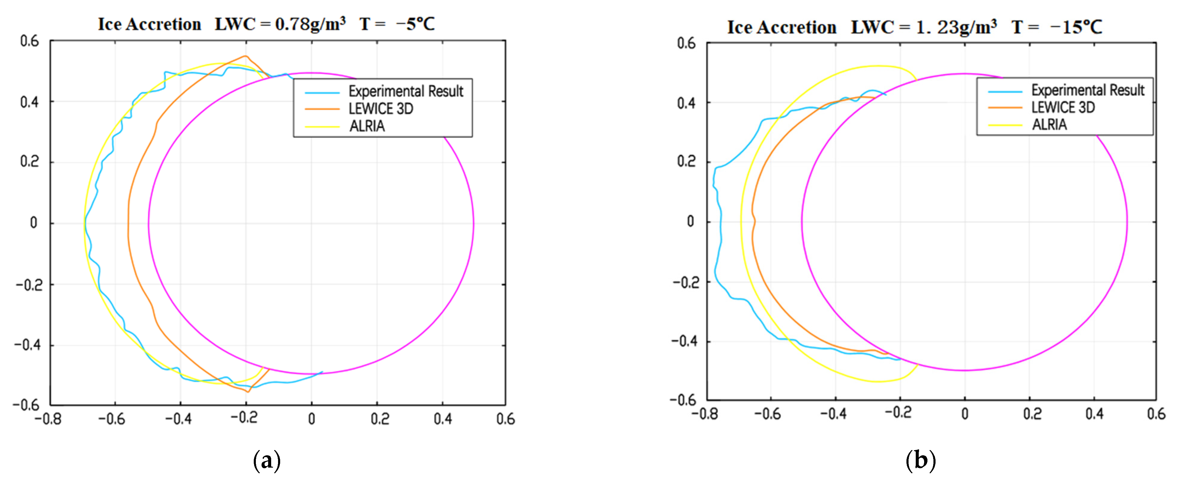
| Avery and Jacob [21] | 2022 | Numerical simulation and lab tests | A cylindrical volume icing model called ALRIA was established and validated. |
| Oswald et al. [22] | 2022 | Numerical simulation | The Spalart Allmaras turbulence model was limited in its applicability to estimating aerodynamic losses caused by ice at low Reynolds numbers. |
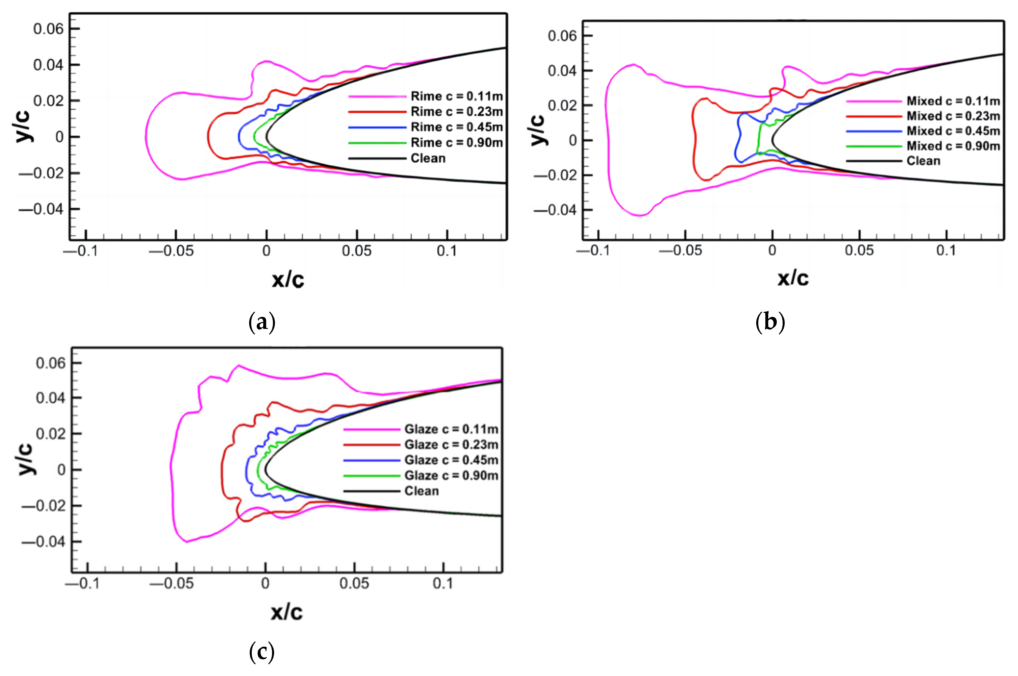
| Hann et al. [24] | 2019 | Numerical simulation and lab tests | The influence of airspeed on frost, mixed ice, and glaze increased sequentially. The relative ice thickness and relative ice limit of smaller airfoils significantly increased. |
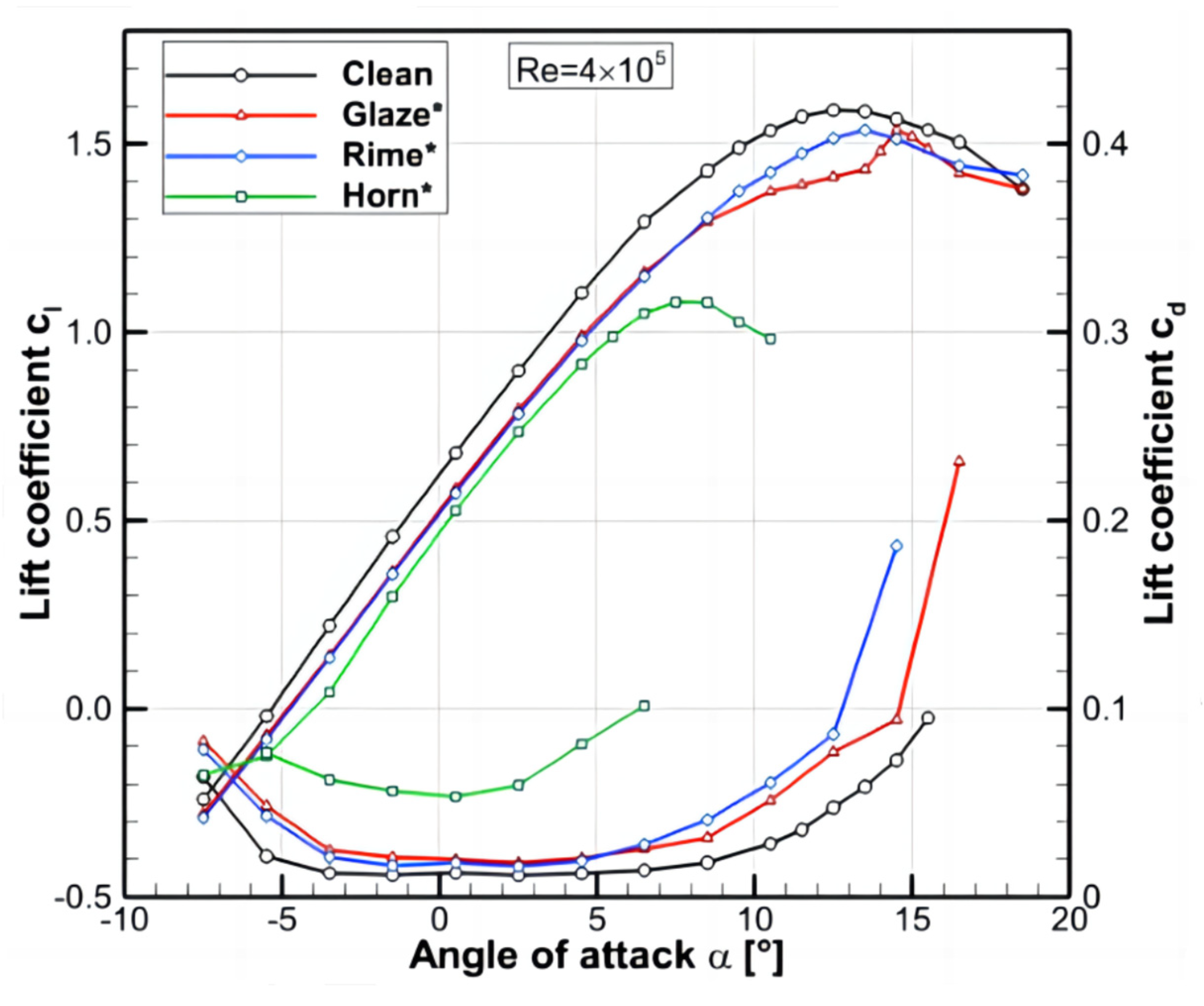
| Hann et al. [26] | 2020 | Numerical simulation and lab tests | Spalart Allmaras and Menter’s k-ω SST model had limitations in simulating complex ice shapes and stall. More complex icing caused greater degradation of flight performance. As the Reynolds number increased, lift increased while drag decreased. |
| Li et al. [27] | 2019 | Lab tests | The surface water reflux on the wing surface using thermoplastic materials was more pronounced [25]. |
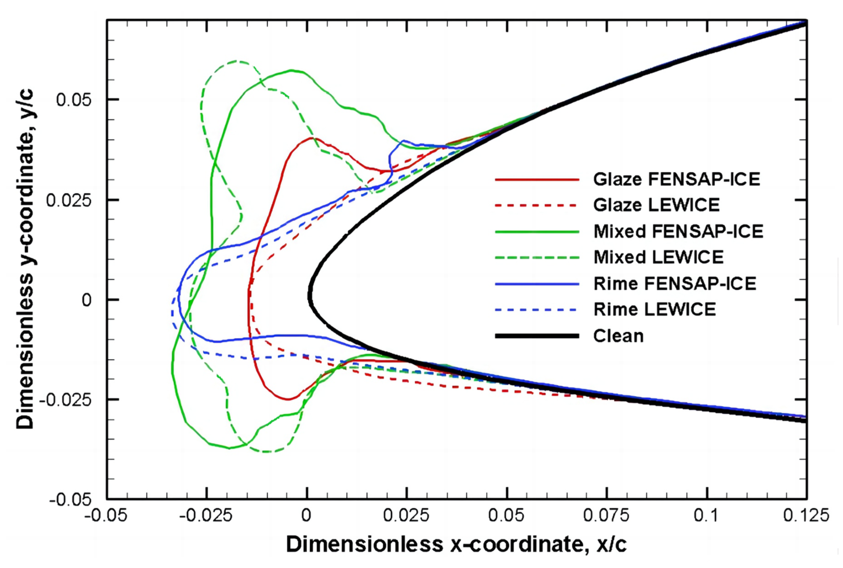
| Hann [32] | 2018 | Numerical simulation | LEWICE and FENSAP-ICE showed good consistency in simulating frost ice, while glaze and mixed ice showed significant differences. |
| Yirtici et al. [33] | 2020 | Numerical simulation | The resistance coefficient predicted by XFOIL method was in good agreement with experimental data, while the lift coefficient was not. |
| Muhammed and Virk [35] | 2023 | Numerical simulation | Transition k-ω SST turbulence model could accurately predict LSB, but it predicted an earlier separation start time. |
| Szilder and McIlwain [36] | 2011 | Numerical simulation | A UAV ice accretion model was developed. As the Reynolds number increased, ice changed from frost ice to mixed ice, and finally became clear ice. |
| Fajt et al. [39] | 2019 | Numerical simulation | Rising temperature caused an increase in ice mass. Ice caused an increase in resistance. |
| Cistriani et al. [43] | 2007 | Lab tests | Ice caused a decrease in lift. |
| Hann et al. [44] | 2017 | Numerical simulation | Ice accumulation increased drag while reducing lift and maximum angle of attack. |
| Szilder et al. [46] | 2015 | Numerical simulation | |
| Oo et al. [49] | 2020 | Lab tests | At low Reynolds numbers, flow reattachment delayed and separation increased. |
| Subject | Researchers | Year | Research Method | Major Achievement or Key Findings |
|---|---|---|---|---|
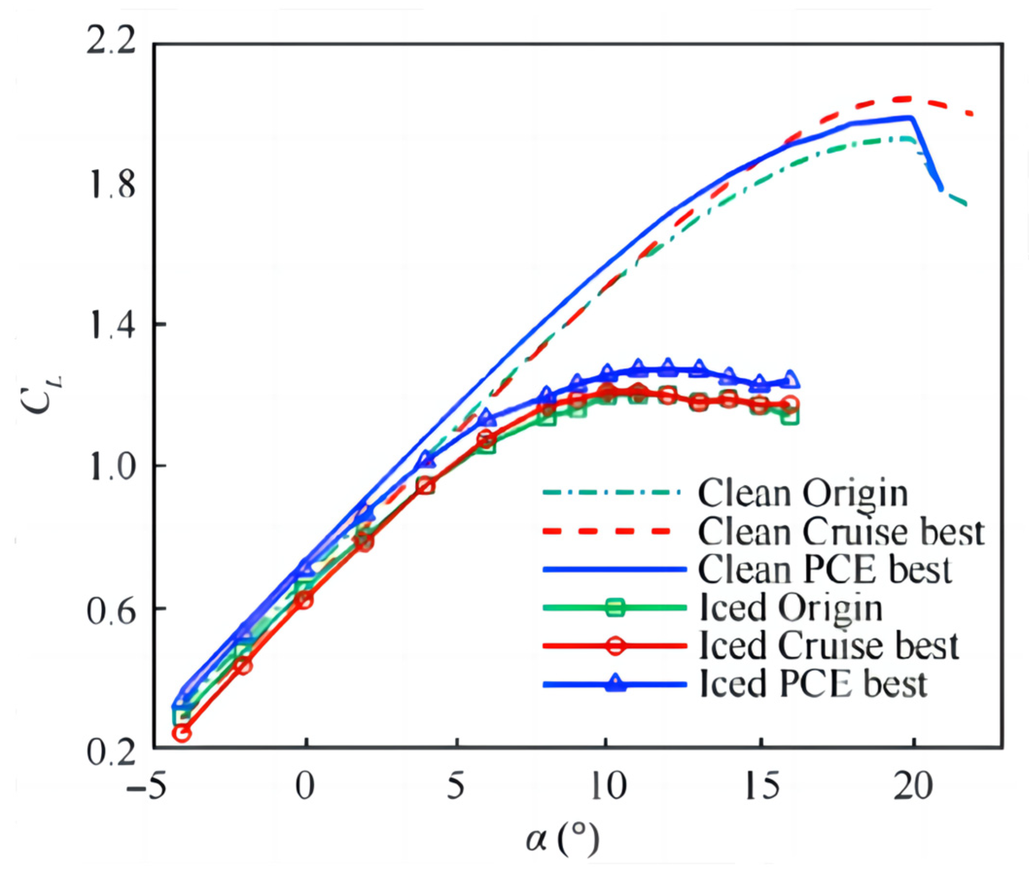
| Airfoil optimization | Li et al. [40] | 2022 | RADE algorithm | “PCE” airfoil had improved icing performance, with a 6.7% increase in maximum lift coefficient. |
| Flight optimization | Narum et al. [86] | 2020 | Particle swarm optimization | A 43% energy efficiency improvement or a 42% flight time reduction between two points. |
| Coatings | Ye et al. [97] | 2021 | Lab tests | A hydrophobic coating system that exhibited a contact angle θ ≥ 115° was created. |
| Luo et al. [98] | 2021 | Lab tests | The PEEK-PEEK/PTFE/k-SiO2 composite coatings for drone metal surfaces were created. | |
| Electric heating combining with coatings | Hann et al. [117] | 2021 | Lab tests | The better design for layout of D•ICE was found. |
| Roy et al. [119] | 2021 | Numerical simulation and lab tests | An integrated electrothermal anti-icing system using a thin etched foil heating film was designed and developed. | |
| Sørensen et al. [120] | 2015 | Numerical simulation and lab tests | A temperature-controlled anti-icing/deicing system for the airfoil of the X8 Skywalker UAV was designed. | |
| Yan et al. [127] | 2023 | Lab tests and flight tests | An anti-icing Skin with Micro-nano Structure was designed and tested. | |
| Zhu [128] | 2018 | Lab tests | A low-energy SHP electric heating anti-icing skin was created. | |
| Plasma | Gao [164] | 2021 | Lab tests | A set of ns-SDBD plasma anti-icing device was created. |
| Synthetic thermal jet | Jiang [172] | 2017 | Lab tests | A novel electromagnetic synthetic dual jet actuator was designed. |
References
- Weatherington, D.; Deputy, U. Unmanned Aircraft Systems Roadmap, 2005–2030; U.S. Department of Defense: Washington, DC, USA, 2005.
- Gao, H.; Yu, P. The Application Prospects of Drones in Emergency Communication. Labor. Prot. 2022, 85–87. (In Chinese) [Google Scholar]
- Villeneuve, E.; Karmouch, E.; Boulerice, X. Development of a small and transportable de-icing/anti-icing drone-mounted system. Part 1: System design. Drone Syst. Appl. 2022, 10, 155–177. [Google Scholar] [CrossRef]
- Bragg, M.B.; Broeren, A.P.; Blumenthal, L.A. Iced-airfoil aerodynamics. Prog. Aerosp. Sci. 2005, 41, 323–362. [Google Scholar] [CrossRef]
- How Is an UAV Affected by In-Flight Icing and Can We Simulate It Accurately? Available online: https://uavicinglab.com/2021/05/28/how-is-an-uav-affected-by-in-flight-icing-and-can-we-simulate-it-accurately/ (accessed on 15 January 2022).
- Haulman, D.L. US Unmanned Aerical Vehicles in Combat 1991–2003; Air Force Historical Research Agency: Montgomery, AL, USA, 2003. [Google Scholar]
- Botura, G.; Fahrner, A. Icing Detection System–Conception, Development, Testing and Applicability to UAVs; AIAA-2003-6637; Goodrich Corp: Akron, OH, USA, 2003. [Google Scholar]
- Szilder, K.; McIlwain, S. In-flight icing of UAVs—The influence of flight speed coupled with chord size. Can. Aeronaut. Sp. J. 2012, 58, 83–94. [Google Scholar] [CrossRef]
- Zhang, B.; Tang, L.; Roemer, M. Probabilistic weather forecasting analysis for unmanned aerial vehicle path planning. J. Guid. Control. Dyn. 2014, 37, 309–312. [Google Scholar] [CrossRef]
- Koenig, G.; Ryerson, C.; Larsson, J.; Reehorst, A. Effect of Variable LWC on Ice Shape in the NASA-GRC IRT. In Proceedings of the 41st Aerospace Sciences Meeting and Exhibit, Reno, NV, USA, 6–9 January 2003. [Google Scholar]
- Lynch, F.; Khodadoust, A. Erratum to “Effects of ice accretions on aircraft aerodynamics”. Prog. Aerosp. Sci. 2002, 38, 669–767. [Google Scholar] [CrossRef]
- Siquig, R.A. Impact of Icing on Unmanned Aerial Vehicle (Uav) Operations; Naval Environmental Protection Research Facility: Monterey, CA, USA, 1990. [Google Scholar]
- Papadopoulos, C.; Ioannidou, S.; Panagiotou, P.; Yakinthos, K. Numerical investigation of the impact of tubercles and wing fences on the aerodynamic behaviour of a fixed-wing, tactical Blended-Wing-Body UAV platform. IOP Conf. Ser. Mater. Sci. Eng. 2022, 1226, 012015. [Google Scholar] [CrossRef]
- Samad, A.; Villeneuve, E.; Blackburn, C.; Morency, F.; Volat, C. An Experimental Investigation of the Convective Heat Transfer on a Small Helicopter Rotor with Anti-Icing and De-Icing Test Setups. Aerospace 2021, 8, 96. [Google Scholar] [CrossRef]
- Bottyán, Z. In-flight icing characteristics of unmanned aerial vehicles during special atmospheric condition over the carpathian-basin. Landsc. Environ. 2013, 7, 74–80. [Google Scholar]
- Williams, N.B.A.; Brian, G.; Ol, M. The Effect of Icing on Small Unmanned Aircraft Low Reynolds Number Airfoils. In Proceedings of the 17th Australian International Aerospace Congress (AIAC), Melbourne, Australia, 26–28 February 2017. [Google Scholar]
- Matiychyk, L.; Suvorova, N.; Tereshchenko, D.; Plakhotniuk, I.; Trachuk, K.; Komarova, K. Influence of Icing on Aircraft Performance of Unmanned Aerial Vehicle M-10-2 “Oko”. Proc. Natl. Aviat. Univ. 2017, 4, 52–59. [Google Scholar] [CrossRef]
- Avery, A.S. Ice Accretion on Small Unmanned Aircraft. Ph.D. Thesis, Oklahoma State University, Stillwater, OK, USA, 2019. [Google Scholar]
- Siddique, M.A. An Experimental Study on the Effects of Adverse Weathers on the Flight Performance of an Unmanned-Aerial-System (UAS). Ph.D. Thesis, Iowa State University, Ames, IA, USA, 2021. [Google Scholar]
- Han, N.H.; Siddique, M.A.; Zhang, Z.C.; Tian, L.C.; Hu, H.Y.; Hu, H. A flight-testing campaign to examine inflight icing characteristics and its effects on the flight performance of an Unmanned-Aerial-Vehicle. Cold Reg. Sci. Technol. 2023, 207, 103775. [Google Scholar] [CrossRef]
- Avery, A.S.; Jacob, J.D. Ice accretion panel model for cylinders at low Reynolds numbers. Bull. Atmos. Sci. Technol. 2022, 3, 7. [Google Scholar] [CrossRef]
- Oswald, J.W.; Enache, A.; Hann, R.; Glabeke, G.; Lutz, T. UAV Icing: Experimental and Numerical Study of Glaze Ice Performance Penalties on an RG-15 Airfoil. In Proceedings of the AIAA SCITECH 2022 Forum, San Diego, CA, USA & Virtual, 3–7 January 2022. [Google Scholar]
- Hann, R. UAV Icing: Ice Accretion Experiments and Validation. In Proceedings of the International Conference on Icing of Aircraft, Engines, and Structures, Minneapolis, MN, USA, 17–21 June 2019. [Google Scholar]
- Hann, R.; Johansen, T.A. UAV icing: The influence of airspeed and chord length on performance degradation. Aircr. Eng. Aerosp. Technol. 2021, 93, 832–841. [Google Scholar] [CrossRef]
- Hann, R. Atmospheric Ice Accretions, Aerodynamic Icing Penalties, and Ice Protection Systems on Unmanned Aerial Vehicles. Ph.D. Thesis, Norwegian University of Science and Technology, Trondheim, Norway, 2020. [Google Scholar]
- Hann, R.; Hearst, R.J.; Sætran, L.; Bracchi, T. Experimental and Numerical Icing Penalties of an S826 Airfoil at Low Reynolds Numbers. Aerospace 2020, 7, 46. [Google Scholar] [CrossRef]
- Li, L.K.; Liu, Y.; Zhang, Z.C.; Hu, H. Effects of thermal conductivity of airframe substrate on the dynamic ice accretion process pertinent to UAS inflight icing phenomena. Int. J. Heat Mass Transf. 2019, 131, 1184–1195. [Google Scholar] [CrossRef]
- Anderson, D.N. Rime-, Mixed-, and Glaze-Iced Evaluations of Three Scaling Laws. In Proceedings of the 36th Aerospace Sciences Meeting and Exhibit, Reno, NV, USA, 10–13 January 1994. [Google Scholar]
- Wright, W.B.; Bidwell, C.S. Additional improvements to the NASA Lewis ice accretion code LEWICE. In Proceedings of the 33rd Aerospace Sciences Meeting and Exhibit, Reno, NV, USA, 9–12 January 1995. [Google Scholar]
- Beaugendre, H.; Morency, F.; Habashi, W.G. FENSAPICE: Roughness effects on ice shape prediction. J. Aircr. 2003, 40, 239–247. [Google Scholar] [CrossRef]
- Hann, R.; Johansen, T.A. Unsettled Topics in Unmanned Aerial Vehicle Icing; SAE EDGE Research Report EPR2020008; SAE International: Warrendale, PA, USA, 2020. [Google Scholar]
- Hann, R. UAV Icing: Comparison of LEWICE and FENSAP-ICE for Ice Accretion and Performance Degradation. In Proceedings of the 2018 Atmospheric and Space Environments Conference, Atlanta, GA, USA, 25–29 June 2018. [Google Scholar]
- Yirtici, O.; Körpe, D.S.; Ozgen, S. Aerodynamic Performance Losses due to Ice Formation on the UAV’s Wing Profile. J. Aeronaut. Space Technol. 2020, 13, 207–215. [Google Scholar]
- XFOIL Subsonic Airfoil Development System. Available online: http://web.mit.edu/drela/Public/web/xfoil/ (accessed on 11 November 2019).
- Muhammed, M.; Virk, M. Steady and Time Dependent Study of Laminar Separation Bubble (LSB) behavior along UAV Airfoil RG-15. Int. J. Multiphysics 2023, 17, 55–76. [Google Scholar]
- Szilder, K.; McIlwain, S. In-Flight Icing of UAVs—The Influence of Reynolds Number on the Ice Accretion Process; SAE Technical Paper 2011-01-2572; SAE International: Warrendale, PA, USA, 2011. [Google Scholar]
- Langmuir, I. A Mathematical Investigation of Water Droplet Trajectories; Army Air Forces Headquarters, Air Technical Service Command: San Antonio, TX, USA, 1946. [Google Scholar]
- Koenig, G.; Ryerson, C.; Kmiec, R. UAV Icing Flight Simulation. In Proceedings of the 40th AIAA Aerospace Sciences Meeting & Exhibit, Reno, NV, USA, 14–17 January 2002. [Google Scholar]
- Fajt, N.; Hann, R.; Lutz, T. The Influence of Meteorological Conditions on the Icing Performance Penalties on a UAV Airfoil. In Proceedings of the 8th European Conference for Aeronautics and Space Sciences (EUCASS), Madrid, Spain, 1–4 July 2019. [Google Scholar]
- Li, H.; Zhang, Y.; Chen, H. Optimization design of airfoils under atmospheric icing conditions for UAV. Chin. J. Aeronaut. 2022, 35, 118–133. [Google Scholar] [CrossRef]
- Bottyán, Z. Estimation of In-Flight Icing Characteristics of UAVs during Different Meteorological Conditions. In Proceedings of the 8th International Conference on Intelligent Unmanned Systems (ICIUS 2012), Singapore, 22 October 2012. [Google Scholar]
- Jeck, R.K. A History and Interpretation of Aircraft Icing Intensity Definitions and FAA Rules for Operating in Icing Conditions; Federal Aviation Administration Technical Report DOT/FAA/AR-01/91; SKYbrary: Anklam, Germany, 2001. [Google Scholar]
- Cistriani, L. Falco UAV Low Reynolds Airfoil Design and Testing at Galileo Avionica. In UAV Design Processes/Design Criteria for Structures; Galileo Avionica Ronchi Dei Legionari (Italy) Simulators and Uav Business Unit; RTO: Neuilly-sur-Seine, France, 2007. [Google Scholar]
- Hann, R.; Wenz, A.; Gryte, K.; Johansen, T.A. Impact of Atmospheric Icing on UAV Aerodynamic Performance. In Proceedings of the 2017 Workshop on Research, Education and Development of Unmanned Aerial Systems (RED-UAS), Linköping, Sweden, 3–5 October 2017. [Google Scholar]
- Oswald, J.W. UAV Icing: Numerical and Experimental Study of Performance Penalties on an RG-15 Airfoil. Master’s Thesis, University of Stuttgart, Stuttgart, Germany, 2021. [Google Scholar]
- Szilder, K.; Yuan, W. The Influence of Ice Accretion on the Aerodynamic Performance of a UAS Airfoil. In Proceedings of the 53rd AIAA Aerospace Sciences Meeting, Kissimmee, FL, USA, 5–9 January 2015. [Google Scholar]
- Hain, R.; Kähler, C.; Radespiel, R. Dynamics of laminar separation bubbles at low-Reynolds-number aerofoils. J. Fluid Mech. 2009, 630, 129–153. [Google Scholar] [CrossRef]
- O’Meara, M.M.; Mueller, T.J. Laminar Separation Bubble Characteristics on an Airfoil at Low Reynolds Numbers. AIAA J. 1987, 25, 1033–1041. [Google Scholar] [CrossRef]
- Oo, N.L.; Richards, P.J.; Sharma, R.N. Ice-Induced Separation Bubble on RG-15 Airfoil at Low Reynolds Number. AIAA J. 2020, 58, 5156–5167. [Google Scholar] [CrossRef]
- Ericsson, L.E.; Reding, J.P. Unsteady Airfoil Stall; NASA Report CR-66787; NASA Center for Aerospace Information: Hanover, MD, USA, 1969.
- Lissaman, P.B.S. Low-Reynolds-number airfoils. Annu. Rev. Fluid Mech. 1983, 15, 223–239. [Google Scholar] [CrossRef]
- Seifert, H.; Richert, F. Aerodynamics of Iced Airfoils and Their Influence on Loads and Power Production. In Proceedings of the European Wind Energy Conference, Dublin, Ireland, 6–9 October 1997; pp. 459–460. [Google Scholar]
- Jasinski, W.J.; Selig, M.S.; Bragg, M.B.; Shawn, C.N. Wind Turbine Performance Under Icing Conditions. J. Sol. Energy Eng. 1998, 120, 60–65. [Google Scholar] [CrossRef]
- Oo, N.L.; Richards, P.; Sharma, R. Influence of an Ice-Induced Separation Bubble on the Laminar Separation Bubble on an RG-15 Airfoil at Low Reynolds Numbers. In Proceedings of the AIAA Aviation 2020 Forum, Virtual, 15–19 June 2020. [Google Scholar]
- Muhammed, M.; Virk, M.S. Ice Accretion on Fixed-Wing Unmanned Aerial Vehicle—A Review Study. Drones 2022, 6, 86. [Google Scholar] [CrossRef]
- Wang, J.; Ji, S.Y.; Yi, X.S.; Zhao, W.M. Research progress in aircraft anti-icing/deicing technology. Aviat. Manuf. Technol. 2015, 495, 30–32. (In Chinese) [Google Scholar]
- Cornell, J.S.; Pillard, D.A.; Hernandez, M.T. Comparative measures of the toxicity of component chemicals in aircraft deicing fluid. Environ. Toxicol. Chem. 2000, 19, 1465–1472. [Google Scholar] [CrossRef]
- Sapienza, R. Environmentally Benign Anti-Icing or Deicing Fluids. U.S. Patent 6,129,857, 2000. [Google Scholar]
- Unmanned Aerial Vehicle Reliability Study; Technical Report; Office of the Secretary of Defense: Washington, DC, USA, 2003.
- Peck, L.; Ryerson, C.; Martel, C. Army Aircraft Icing; Technical Report; Cold Regions Research and Engineering Laboratory: Hanover, HA, USA, 2002. [Google Scholar]
- GA-ASI’s MQ-9B RPAS Undergoes Cold Weather Validation Test. Available online: https://www.airforce-technology.com./news/gaasis-mq9b-cold-weather-validation (accessed on 27 February 2022).
- Dong, W.; Zhu, J.; Zheng, M.; Chen, Y. Thermal analysis and testing of nonrotating cone with hot- air anti-icing system. J. Propuls. Power 2015, 31, 3. [Google Scholar] [CrossRef]
- Boinovich, L.B.; Emelyanenko, A.M. Anti-icing Potential of Superhydrophobic Coatings. Mendeleev Commun 2013, 23, 3–10. [Google Scholar] [CrossRef]
- Farzaneh, M.; Ryerson, C.C. Anti-icing and deicing techniques. Cold Reg. Sci. Technol. 2011, 65, 88–96. [Google Scholar] [CrossRef]
- Shen, Y.Z.; Wu, Y.; Tao, J.; Zhu, C.L.; Chen, H.F.; Wu, Z.W.; Xie, Y.H. Spraying Fabrication of Durable and Transparent Coatings for Anti-Icing Application: Dynamic Water Repellency, Icing Delay, and Ice Adhesion. ACS Appl. Mater. Interfaces 2019, 11, 3590–3598. [Google Scholar] [CrossRef] [PubMed]
- Lv, J.Y.; Song, Y.L.; Jiang, L.; Wang, J.J. Bio-Inspired Strategies for Anti-Icing. ACS Nano 2014, 8, 3152–3169. [Google Scholar] [CrossRef] [PubMed]
- Varanasi, K.K.; Hsu, M.; Bhate, N.; Yang, W.S.; Deng, T. Spatial control in the heterogeneous nucleation of water. Appl. Phys. Lett. 2009, 95, 094101. [Google Scholar] [CrossRef]
- Strobl, T.; Storm, S.; Thompson, D.; Hornung, M.; Thielecke, F. Feasibility study of a hybrid ice protection system. J. Aircr. 2015, 52, 2064–2076. [Google Scholar] [CrossRef]
- Fortin, G.; Adomou, M.; Perron, J. Experimental Study of Hybrid Anti-Icing Systems Combining Thermoelectric and Hydrophobic Coatings; SAE Technical Paper 2011-38-0003; SAE International: Warrendale, PA, USA, 2011. [Google Scholar]
- Ma, L.; Xiong, L.; Liu, L.; Yang, J. Experimental study on electro-thermal deicing technique for carbon fiber composite. Acta Aeronaut. Astronaut. Sin. 2012, 33, 54–61. (In Chinese) [Google Scholar]
- Jiang, H.; Wang, H.T.; Liu, G.; Liu, J.P.; Zhang, X.N.; Chen, Y.Q.; Zhou, W.W. Light-weight, flexible, low-voltage electro-thermal film using graphite nanoplatelets for wearable/smart electronics and deicing devices. J. Alloys Compd. 2017, 699, 1049–1056. [Google Scholar] [CrossRef]
- Rutherford, R.B. De-Ice and Anti-Ice System and Method for Aircraft Surfaces. U.S. Patent 6194685B1, 27 February 2001. [Google Scholar]
- Buschhorn, S.T.; Kessler, S.S.; Lachmann, N.; Gavin, J.; Thomas, G.; Wardle, B.L. Electrothermal Icing Protection of Aerosurfaces Using Conductive Polymer Nanocomposites. In Proceedings of the 54th AIAA/ASME/ASCE/AHS/ASC Structures, Structural Dynamics, and Materials Conference, Boston, MA, USA, 8–11 April 2013; p. 1729. [Google Scholar]
- Strehlow, R.H.; Moser, R. Capitalizing on the Increased Flexibility that Comes from High Power Density Electrothermal Deicing; SAE Technical Paper, 2009-01-3165; SAE International: Warrendale, PA, USA, 2009. [Google Scholar]
- China’s Domestically Produced Large-Scale Unmanned Aerial Vehicle Used for Artificial Weather Modification, the Wing Loong II, Successfully Completed Its Maiden Flight and Got First Place. Available online: http://www.iliema.cn/article-661981-1.html (accessed on 9 January 2022). (In Chinese).
- Guang-Chao, L.I.; Jiang, H.E.; Lin, G.P. Electro-impulse de-icing (EIDI) technology study. J. Aerosp. Power 2011, 26, 1728–1735. [Google Scholar]
- Zumwalt, G.; Friedberg, R. Designing an Electro-Impulse De-Icing System. In Proceedings of the 24th Aerospace Sciences Meeting, Reno, NV, USA, 6–9 January 1986. [Google Scholar]
- Orion UAV Can Perform Ice Reconnaissance in the Arctic. Available online: https://www.airrecognition.com/index.php/news./defense-aviation-news/2021/october/7733-orion-uav-can-perform-ice-reconnaissance-in-the-arctic.html (accessed on 11 October 2021).
- Ghisu, T.; Jarrett, J.P.; Parks, G.T. Robust design optimization of airfoils with respect to ice accretion. J. Aircr. 2011, 48, 287–304. [Google Scholar] [CrossRef]
- Li, H.; Zhang, Y.; Chen, H. Optimization of supercritical airfoil considering the ice-accretion effects. AIAA J. 2019, 57, 4650–4669. [Google Scholar] [CrossRef]
- Dai, J.Z.; Li, H.R.; Zhang, Y.F.; Chen, H.X. Optimization of multi-element airfoil settings considering ice accretion effect. Chin. J. Aeronaut. 2023, 36, 41–57. [Google Scholar] [CrossRef]
- Vukits, T.J. Overview and Risk Assessment of Icing for Transport Category Aircraft And Components. In Proceedings of the 40th AIAA Aerospace Sciences Meeting and Exhibit, Reno, NV, USA, 14–17 January 2002. [Google Scholar]
- Thompson, G. High Resolution Numerical Weather Model Forecasts of Icing at the Ground and in the Air. In Proceedings of the International Workshop on Atmospheric Icing of Structures, Reykjavík, Iceland, 23–28 June 2019. [Google Scholar]
- Niu, J.; Sang, W.; Li, D.; Guo, Q.; Qiu, A.; Shi, M. Fast Prediction of Multiple Parameters Related to Iced Airfoil Based on POD and Kriging Methods. J. Appl. Fluid Mech. 2023, 16, 325–336. [Google Scholar] [CrossRef]
- Hovenburg, A.; de Alcantara Andrade, F.A.; Hann, R.; Dahlin Rodin, C.; Johansen, T.; Storvold, R. Long range path planning using an aircraft performance model for battery powered sUAS equipped with icing protection system. IEEE J. Miniaturization Air Space Syst. 2020, 1, 76–89. [Google Scholar] [CrossRef]
- Narum, E.F.L.; Hann, R.; Johansen, T.A. Optimal Mission Planning for Fixed-Wing UAVs with Electro-Thermal Icing Protection and Hybrid-Electric Power System. In Proceedings of the 2020 International Conference on Unmanned Aircraft Systems (ICUAS), Athens, Greece, 1–4 September 2020; pp. 651–660. [Google Scholar]
- Subramanyam, B.S.; Kondrashov, V.; Ruhe, J.; Varanasi, K.K. Low ice adhesion on nano-textured superhydrophobic surfaces under supersaturated conditions. ACS Appl. Mater. Interfaces 2016, 8, 12583–12587. [Google Scholar] [CrossRef] [PubMed]
- Guo, P.; Zheng, Y.; Wen, M.; Song, C.; Lin, Y.; Jiang, L. Icephobic/anti-icing properties of micro/nanostructured surfaces. Adv. Mater. 2012, 24, 2642–2648. [Google Scholar] [CrossRef] [PubMed]
- Kim, P.; Wong, T.-S.; Alvarenga, J.; Kreder, M.J.; Adorno-Martinez, W.E.; Aizenberg, J. Liquid-infused nanostructured surfaces with extreme anti-ice and anti-frost performance. ACS Nano 2012, 6, 6569–6577. [Google Scholar] [CrossRef]
- Liu, Q.; Yang, Y.; Huang, M.; Zhou, Y.; Liu, Y.; Liang, X. Durability of a lubricant-infused electrospray silicon rubber surface as an anti-icing coating. Appl. Surf. Sci. 2015, 346, 68–76. [Google Scholar] [CrossRef]
- Ozbay, S.; Yuceel, C.; Erbil, H.Y. Improved icephobic properties on surfaces with a hydrophilic lubricating liquid. ACS Appl. Mater. Interfaces 2015, 7, 22067–22077. [Google Scholar] [CrossRef]
- Chen, J.; Luo, Z.; Fan, Q.; Lv, J.; Wang, J. Anti-ice coating inspired by ice skating. Small 2014, 10, 4693–4699. [Google Scholar] [CrossRef]
- Dou, R.; Chen, J.; Zhang, Y.; Wang, X.; Cui, D.; Song, Y.; Jiang, L.; Wang, J. Anti-icing coating with an aqueous lubricating layer. ACS Appl. Mater. Interfaces 2014, 6, 6998–7003. [Google Scholar] [CrossRef]
- Zhao, Z.; Chen, H.; Liu, X.; Liu, H.; Zhang, D. Development of high-efficient synthetic electric heating coating for anti-icing/de-icing. Surf. Coat. Technol. 2018, 349, 340–346. [Google Scholar] [CrossRef]
- Matsubayashi, T.; Tenjimbayashi, M.; Manabe, K.; Komine, M.; Navarrini, W.; Shiratori, S. Integrated anti-icing property of super-repellency and electrothermogenesis exhibited by PEDOT:PSS/cyanoacrylate composite nanoparticles. ACS Appl. Mater. Interfaces 2016, 8, 24212–24220. [Google Scholar] [CrossRef] [PubMed]
- Ye, W.M.; Guo, K.; Qiu, W.P. Research and development of anti icing and hydrophobic coatings for unmanned aerial vehicles. Mech. Electr. Inf. 2021, 672, 18–20. (In Chinese) [Google Scholar]
- Luo, H.Y.; Li, Y.; Huan, D.J.; Zhu, C.L.; Wang, J.X.; Zeng, D. Efficient Fabrication of Wear-Resistant PEEK Matrix Composite Coating with Superhydrophobicity for Self-Cleaning and Anti-Icing Applications. Polym.-Plast. Technol. Mater. 2021, 60, 1106–1121. [Google Scholar] [CrossRef]
- Wong, T.S.; Kang, S.H.; Tang, S.K.Y.; Smythe, E.J.; Hatton, B.D.; Grinthal, A.; Aizenberg, J. Bioinspired self-repairing slippery surfaces with pressure-stable omniphobicity. Nature 2011, 477, 443–447. [Google Scholar] [CrossRef] [PubMed]
- Liu, X.L.; Chen, H.W.; Zhao, Z.H.; Yan, Y.Y.; Zhang, D.Y. Slippery liquid-infused porous electric heating coating for anti-icing and deicing applications. Surf. Coat. Technol. 2019, 374, 889–896. [Google Scholar] [CrossRef]
- Hann, R.; Borup, K.; Zolich, A.; Sorensen, K.; Vestad, H.; Steinert, M.; Johansen, T. Experimental Investigations of an Icing Protection System for UAVs; SAE Technical Paper 2019-01-2038; SAE International: Warrendale, PA, USA, 2019. [Google Scholar]
- Zhao, Z.H.; Chen, H.W.; Liu, X.L.; Wang, Z.L.L.; Zhu, Y.T.; Zhou, Y.P. The development of electric heating coating with temperature controlling capability for anti-icing/de-icing. Cold Reg. Sci. Technol. 2021, 184, 103234. [Google Scholar] [CrossRef]
- Yao, X.D.; Hawkins, S.C.; Falzon, B.G. An advanced anti-icing/de-icing system utilizing highly aligned carbon nanotube webs. Carbon 2018, 136, 130–138. [Google Scholar] [CrossRef]
- Pan, L.; Liu, Z.; Kiziltaş, O.; Zhong, L.; Pang, X.; Wang, F.; Zhu, Y.; Ma, W.; Lv, Y. Carbon fiber/poly ether ether ketone composites modified with graphene for electro-thermal deicing applications. Compos. Sci. Technol. 2020, 192, 108117. [Google Scholar] [CrossRef]
- Karim, N.; Zhang, M.; Afroj, S.; Koncherry, V.; Potluri, P.; Novoselov, K.S. Graphene-based surface heater for de-icing Applications. RSC Adv. 2018, 8, 16815–16823. [Google Scholar] [CrossRef]
- Cortés, A.; Romate, X.F.S.; Jiménez-Suárez, A.; Campo, M.; Prolongo, M.G.; Ureña, A.; Prolongo, S.G. 3D printed anti-icing and de-icing system based on CNT/GNP doped epoxy composites with self-curing and structural health monitoring capabilities. Smart Mater. Struct. 2021, 30, 025016. [Google Scholar] [CrossRef]
- Wang, T.; Zheng, Y.; Raji, A.-R.O.; Li, Y.; Sikkwma, W.K.A.; Tour, J.M. Passive anti-icing and active deicing films. ACS Appl Mater Interfaces 2016, 8, 14169–14173. [Google Scholar] [CrossRef] [PubMed]
- Falin, A.; Cai, Q.; Santos, E.J.G.; Scullion, D.; Qian, D.; Zhang, R.; Yang, Z.; Huang, S.; Watanabe, K.; Taniguchi, T.; et al. Mechanical properties of atomically thin boron nitride and the role of interlayer interactions. Nat. Commun. 2017, 8, 15815. [Google Scholar] [CrossRef] [PubMed]
- Thomassin, J.-M.; Jérôme, C.; Pardoen, T.; Bailly, C.; Huynen, I.; Detrembleur, C. Polymer/carbon based composites as electromagnetic interference (EMI) shielding materials. Mater. Sci. Eng. R Rep. 2013, 74, 211–232. [Google Scholar] [CrossRef]
- Hwang, H.; Ma, K.Y.; Kim, J.W.; Yuk, D.; Hong, J.; Jung, J.H.; Yong, S.; Choi, J.; Kim, J.Y.; Shin, H.S. Radio-frequency-transmitting hexagonal boron nitride-based antiand de-icing heating system. Nanoscale 2020, 12, 21895–21900. [Google Scholar] [CrossRef] [PubMed]
- Vertuccio, L.; De Santis, F.; Pantani, R.; Lafdi, K.; Guadagno, L. Effective de-icing skin using graphene-based flexible heater. Compos. Part B Eng. 2019, 162, 600–610. [Google Scholar] [CrossRef]
- Ming, Y.K.; Duan, Y.G.; Zhang, S.Q.; Zhu, Y.; Wang, B.W. Self-heating 3D printed continuous carbon fiber/epoxy mesh and its application in wind turbine deicing. Polym. Test. 2020, 82, 106309. [Google Scholar] [CrossRef]
- Galao, O.; Bañón, L.; Baeza, F.; Carmona, J.; Garcés, P. Highly conductive carbon fiber reinforced concrete for icing prevention and curing. Materials 2016, 9, 281. [Google Scholar] [CrossRef]
- Zhao, H.; Wu, Z.; Wang, S.; Zheng, J.; Che, G. Concrete pavement deicing with carbon fiber heating wires Cold Reg. Sci. Technol. 2011, 65, 413–420. [Google Scholar]
- Idris, M.K.; Qiu, J.F.; Melenka, G.W.; Grau, G. Printing electronics directly onto carbon fiber composites: Unmanned aerial vehicle (UAV) wings with integrated heater for de-icing. Eng. Res. Express 2020, 2, 025022. [Google Scholar] [CrossRef]
- Xu, X.; Wang, F.; Mao, J. The flexible pressure-sensitive adhesive graphene-based composite heater based on the laminating structure for de-icing applications. J. Mater. Sci. Mater. Electron. 2021, 32, 13994–14005. [Google Scholar] [CrossRef]
- Hann, R.; Enache, A.; Nielsen, M.C.; Stovner, B.N.; Beeck, J.V.; Johansen, T.A.; Borup, K.T. Experimental Heat Loads for Electrothermal Anti-Icing and De-Icing on UAVs. Aerospace 2021, 8, 83. [Google Scholar] [CrossRef]
- SAE International. Ice, Rain, Fog, and Frost Protection; Aerospace Information Report AIR1168/4; SAE International: Warrendale, PA, USA, 2016. [Google Scholar]
- Roy, R.; Raj, L.P.; Jo, J.-H.; Cho, M.-Y.; Kweon, J.-H.; Myong, R.S. Multiphysics anti-icing simulation of a CFRP composite wing structure embedded with thin etched-foil electrothermal heating films in glaze ice conditions. Compos. Struct. 2021, 276, 114441. [Google Scholar] [CrossRef]
- Sørensen, K.L.; Helland, A.S.; Johansen, T.A. Carbon Nanomaterial-Based Wing Temperature Control System for In-Flight Anti-Icing and De-Icing of Unmanned Aerial Vehicles. In Proceedings of the IEEE Aerospace Conference Proceedings, Big Sky, MT, USA, 7–14 March 2015. [Google Scholar]
- Sørensen, K.L.; Johansen, T.A. Thermodynamics of a Carbon Nano-Materials Based Icing Protection System for Unmanned Aerial Vehicle. In Proceedings of the IEEE Aerospace Conference, Big Sky, MT, USA, 5–12 March 2016. [Google Scholar]
- Warwick, G. Nanotech promises energy-efficient anti-icing. Aviat. Week Space Technol. 2012, 174, 15. [Google Scholar]
- Grinats, É.S.; Miller, A.B.; Potapov, Y.F.; Stasenko, A.L. Experimental and theoretical investigations of the processes of icing of nanomodified superhydrophobic and ordinary surfaces. Vestn. Moskovsk. Gos. Obl. Univ. Ser. Fiz.-Mat. 2013, 3, 84–92. [Google Scholar]
- Bogoslov, E.A.; Danilaev, M.P.; Mikhailov, S.A.; Pol′skii, Y.E. Energy efficiency of an integral anti-ice system based on fluoroplastic films. J. Eng. Phys. Thermophys. 2016, 89, 815–820. [Google Scholar] [CrossRef]
- Battelle’s Anti-Icing System for Remotely Piloted Aircraft (RPAs). Available online: http://www.battelle.org (accessed on 14 August 2013).
- Yan, Z.X.; He, Y.; Yuan, W.Z.; Yuan, W.Z. Anti-icing Skin with Micro-nano Structure Inspired by Fargesia Qinlingensis. Trans. Nanjing Univ. Aeronaut. Astronaut. 2023, 2, 115–123. [Google Scholar]
- Zhu, B. Low Power Superhydrophobic Electrothermal Skin and Its Anti-icing Performance. Master’s Thesis, Northwestern Polytechnical University, Xi’an, China, 2018. (In Chinese). [Google Scholar]
- Deshpande, S.; Sæterdal, A.; Sundsbø, P.-A. Sea Spray Icing: The physical process and review of prediction models and winterization techniques. J. Offshore Mech. Arct. Eng. 2021, 143, 061601. [Google Scholar] [CrossRef]
- Villeneuve, E.; Harvey, D.; Zimcik, D.; Aubert, R.; Perron, J. Piezoelectric deicing system for rotorcraft. J. Am. Helicopter Soc. 2015, 60, 1–12. [Google Scholar] [CrossRef]
- Venna, S.V.; Lin, Y.J. In-Flight De-Icing Self-Actuating Wing Structures with Piezoelectric Actuators. In Proceedings of the American Society of Mechanical Engineers/International Mechanical Engineering Congress and Exposition, New Orleans, LA, USA, 17–22 November 2002; pp. 237–245. [Google Scholar]
- Yao, S.J. Research on Wing Deicing Method Based on Piezoelectric Drivers. Master’s Thesis, Nanjing University of Aeronautics and Astronautics, Nanjing, China, 2010. [Google Scholar]
- Bai, T. Ice Detection and Deicing Method Based on Piezoelectric Materials. Ph.D. Thesis, Nanjing University of Aeronautics and Astronautics, Nanjing, China, 2015. [Google Scholar]
- Palacios, J.; Smith, E.; Rose, J.; Royer, R. Ultrasonic de-icing of wind-tunnel impact icing. J. Aircr. 2011, 48, 1020–1027. [Google Scholar] [CrossRef]
- Palacios, J.; Smith, E.; Rose, J. Investigation of an Ultrasonic Ice Protection System for Helicopter Rotor Blades. Annu. Forum Proc.—AHS Int. 2008, 1, 609–618. [Google Scholar]
- Tarquini, S.; Antonini, C.; Amirfazli, A.; Marengo, M.; Palacios, J. Investigation of Ice Shedding Properties of Superhydrophobic Coatings on Helicopter Blades. Cold Reg. Sci. Technol. 2014, 100, 50–58. [Google Scholar] [CrossRef]
- Overmeyer, A.; Palacios, J.; Smith, E. Ultrasonic de-icing bondline design and rotor ice testing. AIAA J. 2013, 51, 2965–2976. [Google Scholar] [CrossRef]
- Budinger, M.; Pommier-Budinger, V.; Napias, G.; Silva, A.C. Ultrasonic ice protection systems: Analytical and numerical models for architecture tradeoff. J. Aircr. 2016, 53, 680–690. [Google Scholar] [CrossRef]
- Venna, S.V.; Lin, Y.J. Development of Self-Actuating In-Flight De-Icing Structures with Power Consumption Considerations. In Proceedings of the American Society of Mechanical Engineers International Mechanical Engineering Congress and Exposition, Washington, DC, USA, 17–22 November 2003; pp. 45–53. [Google Scholar]
- Venna, S.V.; Lin, Y.J. Mechatronic Development of Self-Actuating In-Flight De-Icing Structures. IEEE/ASME Trans. Mechatron. 2006, 11, 585–592. [Google Scholar] [CrossRef]
- Venna, S.; Lin, Y.J.; Botura, G. Piezoelectric Transducer Actuated Leading Edge De-Icing with Simultaneous Shear and Impulse Forces. J. Aircr. 2007, 44, 509–515. [Google Scholar] [CrossRef]
- Struggl, S.; Korak, J.; Feyrer, C. A Basic Approach for Wing Leading De-Icing by Smart Structures. In Proceedings of the SPIE Smart Structures and Materials + Nondestructive Evaluation and Health Monitoring, San Diego, CA, USA, 6–10 March 2011. [Google Scholar]
- Palanque, V. Design of Low Consumption Electro-Mechanical De-Icing Systems. Ph.D. Thesis, Université de Toulouse ISAE-Supaero, Toulouse, France, 2022. [Google Scholar]
- Tan, M.K.; Friend, J.R.; Yeo, L.Y. Interfacial Jetting Phenomena Induced by Focused Surface Vibrations. Phys. Rev. Lett. 2009, 103, 024501. [Google Scholar] [CrossRef]
- Qi, A.; Yeo, L.Y.; Friend, J.R. Interfacial Destabilization and Atomization Driven by Surface Acoustic Waves. Phys. Fluids 2008, 20, 074103. [Google Scholar] [CrossRef]
- Li, L.; Wu, E.; Jia, K.; Yang, K. Temperature Field Regulation of a Droplet Using an Acoustothermal Heater. Lap Chip 2021, 21, 3184–3194. [Google Scholar] [CrossRef]
- Mehmood, M.; Nawaz Chaudhary, T.; Burnside, S.; Khan, U.F.; Yongqing Fu, R.; Chen, B. Coupling Mechanism of Kinetic and Thermal Impacts of Rayleigh Surface Acoustic Waves on the Microdroplet. Exp. Therm. Fluid Sci. 2022, 133, 110580. [Google Scholar] [CrossRef]
- Jacob, S.; Pandey, S.; Moral, J.D.; Karimzadeh, A.; Gil-Rostra, J.; González-Elipe, A.R.; Borrás, A.; Winkler, A. Surface Acoustic Waves Equip Materials with Active Deicing Functionality: Unraveled Deicing Mechanisms and Application to Centimeter Scale Transparent Surfaces. Adv. Mater. Technol. 2023, 8, 2300263. [Google Scholar] [CrossRef]
- Zeng, X.; Yan, Z.; Lu, Y.; Fu, Y.; Lv, X.; Yuan, W.; He, Y. Reduction of Ice Adhesion Using Surface Acoustic Waves: Nanoscale Vibration and Interface Heating Effects. Langmuir 2021, 37, 11851–11858. [Google Scholar] [CrossRef] [PubMed]
- Nampoothiri, K.N.; Nath, A.; Satpathi, N.S.; Sen, A.K. Deicing of Sessile Droplets Using Surface Acoustic Waves. Langmuir 2023, 39, 3934–3941. [Google Scholar] [CrossRef] [PubMed]
- Roth, J.R.; Sherman, D.M.; Wilkinson, S.P. Boundary Layer Flow Control with a One Atmosphere Uniform Glow Discharge Surface Plasma. In Proceedings of the 36th AIAA Aerospace Sciences Meeting and Exhibit, Reno, NV, USA, 12–15 January 1998. AIAA-98-0328. [Google Scholar]
- Winkel, R.; Correale, G.; Kotsonis, M. Effect of Dielectric Material on Thermal Effect Produced by ns-DBD Plasma Actuator. In Proceedings of the 45th AIAA Plasma Dynamics and Lasers Conference, Atlanta, GA, USA, 16–20 June 2014. AIAA-2014-2119. [Google Scholar]
- Li, Q.Q.; Hao, L.Y. Surface Dielectric Barrier Discharge Plasma and Its Applications. High Volt. Technol. 2016, 42, 1079–1090. (In Chinese) [Google Scholar]
- Cai, J.; Tian, Y.; Meng, X.; Han, X.; Zhang, D.; Hu, D. An experimental study of icing control using DBD plasma actuator. Exp. Fluids 2017, 58, 102. [Google Scholar] [CrossRef]
- Kolbakir, C.; Liu, Y.; Starikovskiy, A.; Miles, R.B.; Hu, H. An Experimental Investigation on The Thermal Effects of NS-DBD and AC-DBD Plasma Actuators for Aircraft Icing Mitigation. In Proceedings of the AIAA Science and Technology Forum and Exposition, Kissimmee, FL, USA, 8–12 January 2018. AIAA-2018-0164. [Google Scholar]
- Liu, Y.; Hu, H. An experimental investigation on the unsteady heat transfer process over an ice accreting airfoil surface. Int. J. Heat Mass Transf. 2018, 122, 707–718. [Google Scholar] [CrossRef]
- Liu, Y.; Kolbakir, C.; Hu, H. A Comparison Study on AC-DBD Plasma and Electrical Heating for Aircraft Icing Mitigation. In Proceedings of the AIAA Science and Technology Forum and Exposition, Kissimmee, FL, USA, 8–12 January 2018. AIAA-2018-0167. [Google Scholar]
- Zhu, Y.; Starikovskaia, S. Fast gas heating of nanosecond pulsed surface dielectric barrier discharge: Spatial distribution and fractional contribution from kinetics. Plasma Sources Sci. Technol. 2018, 27, 124007. [Google Scholar] [CrossRef]
- Zhu, Y.; Wu, Y.; Wei, B.; Xu, H.; Liang, H.; Jia, M.; Song, H.; Li, Y. Nanosecond-pulsed dielectric barrier discharge-based plasma-assisted anti-icing: Modeling and mechanism analysis. J. Phys. D Appl. Phys. 2020, 53, 145205. [Google Scholar] [CrossRef]
- Wei, B.; Wu, Y.; Liang, H.; Zhu, Y.; Chen, J.; Zhao, G.; Xu, H. SDBD based plasma anti-icing: A streamwise plasma heat knife configuration and criteria energy analysis. Int. J. Heat Mass Transf. 2019, 138, 163–172. [Google Scholar] [CrossRef]
- Wei, B.; Wu, Y.; Liang, H.; Chen, J.; Zhao, G.; Tian, M.; Xu, H. Performance and mechanism analysis of nanosecond pulsed surface dielectric barrier discharge based plasma deicer. Phys. Fluids 2019, 31, 091701. [Google Scholar] [CrossRef]
- Niu, J.J.; Sang, W.M.; Zhou, F.; Li, D. Numerical investigation of an anti-icing method on airfoil based on the NSDBD plasma actuator. Aircr. Eng. Aerosp. Technol. 2021, 93/4, 592–606. [Google Scholar] [CrossRef]
- Gao, X.L. Development of High-frequency ns-SDBD Plasma Generator and Preliminary Study on Anti-Icing Experiment. Master’s Thesis, Chongqing University, Chongqing, China, 2021. (In Chinese). [Google Scholar]
- Liu, Y.; Kolbakir, C.; Starikovskiy, A.Y.; Miles, R.; Hu, H. An experimental study on the thermal characteristics of NS-DBD plasma actuation and application for aircraft icing mitigation. Plasma Sources Sci. Technol. 2019, 28, 014001. [Google Scholar] [CrossRef]
- Luo, Z.B.; Xia, Z.X. Advances in synthetic jet technology and applications in flow control. Adv. Mech. 2005, 35, 220–234. (In Chinese) [Google Scholar]
- Smith, B.L.; Glezer, A. The formation and evolution of synthetic jets. Phys. Fluids 1998, 10, 2281–2297. [Google Scholar] [CrossRef]
- Nagappan, N.; Golubev, V.V. On Icing Control Using Thermally Activated Synthetic Jets. In Proceedings of the 51st AIAA Aerospace Sciences Meeting including the New Horizons Forum and Aerospace Exposition, Grapevine, TX, USA, 7–10 January 2013. [Google Scholar]
- Nagappan, N.; Golubev, V.V. Parametric Analysis of Icing Control Using Synthetic Jet Actuators. In Proceedings of the 21st AIAA Computational Fluid Dynamics Conference, San Diego, CA, USA, 24–27 June 2013. [Google Scholar]
- Nagappan, N. Numerical Modeling of Anti-Icing Using an Array of Heated Synthetic Jets. Ph.D. Thesis, Embry-Riddle Aeronautical University, Daytona Beach, FL, USA, 2013. [Google Scholar]
- Li, Y.J. Research on Airfoil Separate Flow Control and Airfoil Icing Control Using Dual Synthetic Jet Actuator. Master’s Thesis, National University of Defense Technology, Changsha, China, 2015. (In Chinese). [Google Scholar]
- Li, Y.J.; Luo, Z.B. An experimental investigation on the process of droplet icing/frosting and defrosting/deicing using dual synthetic jet. J. Exp. Fluid Mech. 2016, 30, 27–32. (In Chinese) [Google Scholar]
- Jiang, H. Research on Anti-Icing/De-Icing Using the Heated Dual Synthetic Jet Technology. Master’s Thesis, National University of Defense Technology, Changsha, China, 2017. (In Chinese). [Google Scholar]
- Liu, X.C.; Liang, H.; Zong, H.H.; Xie, L.K.; Su, Z. Experimental investigation on de-icing by an array of impact rod-type plasma synthetic jets. Plasma Sci. Technol. 2023, 25, 035504. [Google Scholar] [CrossRef]
- Gao, T.X.; Luo, Z.B.; Zhou, Y.; Yang, S.K. A novel de-icing strategy combining electric-heating with plasma synthetic jet actuator. Proc. IMechE Part G J. Aerosp. Eng. 2020, 235, 095441002094472. [Google Scholar] [CrossRef]


| Techniques | Pros | Cons | Applications |
|---|---|---|---|
| Pneumatic type | Simple operation and low cost | Large mass, easily damaged pneumatic sleeve | —— |
| Liquid | No energy consumption | Large mass, short effective time | RQ-1B UAV MQ-9B UAV |
| Hot air | Air source available on aircraft | No air source on drones | —— |
| Coating | No energy consumption | Short effective time | Wing Loong II UAV |
| Electric type | Good anti-icing/deicing effect and mature system | High energy consumption with overflow ice | Wing Loong II UAV |
| Electric pulse type | Low energy consumption and good deicing effect | Composite materials are not easy to generate magnetic fields | Orion UAV |
Disclaimer/Publisher’s Note: The statements, opinions and data contained in all publications are solely those of the individual author(s) and contributor(s) and not of MDPI and/or the editor(s). MDPI and/or the editor(s) disclaim responsibility for any injury to people or property resulting from any ideas, methods, instructions or products referred to in the content. |
© 2023 by the authors. Licensee MDPI, Basel, Switzerland. This article is an open access article distributed under the terms and conditions of the Creative Commons Attribution (CC BY) license (https://creativecommons.org/licenses/by/4.0/).
Share and Cite
Zhou, L.; Yi, X.; Liu, Q. A Review of Icing Research and Development of Icing Mitigation Techniques for Fixed-Wing UAVs. Drones 2023, 7, 709. https://doi.org/10.3390/drones7120709
Zhou L, Yi X, Liu Q. A Review of Icing Research and Development of Icing Mitigation Techniques for Fixed-Wing UAVs. Drones. 2023; 7(12):709. https://doi.org/10.3390/drones7120709
Chicago/Turabian StyleZhou, Liang, Xian Yi, and Qinglin Liu. 2023. "A Review of Icing Research and Development of Icing Mitigation Techniques for Fixed-Wing UAVs" Drones 7, no. 12: 709. https://doi.org/10.3390/drones7120709
APA StyleZhou, L., Yi, X., & Liu, Q. (2023). A Review of Icing Research and Development of Icing Mitigation Techniques for Fixed-Wing UAVs. Drones, 7(12), 709. https://doi.org/10.3390/drones7120709