Article

Competition and Cooperation for Multiple Solar Powered Unmanned Aerial Vehicles under Static Soaring

School of Aeronautic Science and Engineering, Beihang University, Beijing 102206, China
*
Author to whom correspondence should be addressed.
Drones 2023, 7(11), 653; https://doi.org/10.3390/drones7110653
Submission received: 22 September 2023 / Revised: 25 October 2023 / Accepted: 28 October 2023 / Published: 31 October 2023

Abstract

:
This work examines the competition and allocation of multiple solar-powered unmanned aerial vehicles (SUAVs) to a single thermal since multiple SUAVs often demonstrate superior mission performance compared to a single SUAV. Additionally, they can harvest extra energy from thermal updrafts. This work considers two conditions, a non-cooperative competition and a cooperative allocation of thermal. In each case, corresponding objective functions and constraints are established, and assignment schemes are derived by solving these objective functions. The allocation results are simulated and integrated with the dynamics and solar energy model. The numerical results show that, in the non-cooperative mode, the first vehicle to reach the thermal can occupy it for soaring, while the remaining SUAVs will fly towards the destination directly. But in the cooperative mode, the multiple SUAVs will allocate the thermal to the SUAV with the highest energy gain through soaring, to maximize the overall electric energy storage of the SUAV group.

1. Introduction

Solar-powered unmanned aerial vehicles (SUAVs) have potential applications in both military and civilian fields due to their long endurance. Scholars have investigated the SUAV performance in communication [1], surveillance [2], and eavesdropping [3]. An SUAVs’ endurance is mainly affected by weather conditions and battery capacity, which restricts their ability to accomplish missions. Thus, SUAVs need to harvest extra energy from atmospheric thermals to extend their endurance. A thermal updraft is formed by a ground-based hot spot that generates a thermal gradient, heating the surrounding air [4]. Some birds and small fixed-wing UAVs can employ this natural phenomenon by soaring to increase their altitude [5]. The models and character of thermals has been investigated [6] in order to achieve better soaring performance.
Thermal center estimation is a significant factor when taking advantage of thermals for soaring. Various methods based on different principles have been proposed to identify and exploit thermals, for example, optimal control [7], feedback control [8], particle filter [9], and reinforcement learning [10]. In addition to thermal center estimation, some studies focus on thermal applications by UAVs. Rosales and Gross [11] found the power consumption of the UAV during soaring was primarily influenced by its mass rather than the bank angle or lift coefficient. Khaghani et al. [12] proposed an environment model and control strategy to enhance the compatibility of UAVs with bird soaring behavior. Tin et al. [13] proposed a turn decision-making algorithm at the start of thermal detection to improve soaring performance. Wu et al. analyzed the effect of different conditions on the stored electric energy performance of a single SUAV during soaring [14]. Furthermore, the SUAV charging process has been verified by experiments [15], while the optimal bank angle of the SUAV during soaring has been calculated to combine the benefits of solar energy and thermals [16].
Solar power is the main energy source for SUAVs. Scholars have studied the variation of electric energy storage for SUAVs during flight so they can maintain as much energy as possible. Considering the UAV’s limits and external restrictions, Mateja et al. developed a simulation model to accurately calculate the energy obtained by solar cells [17]. Li et al. analyzed the energy balance of the SUAV during flight to assist in the design of the energy system [18]. Wu et al. proposed the concept of an endurance map to estimate the endurance evaluation of SUAV, combined with the effect of latitude, longitude, and temperature on the solar cell [19]. Huang et al.built an energy maximum objective function and obtained the optimal path for moving target tracking [20] and fixed target tracking [21] missions, respectively. Maintaining the energy maximum trajectory, Hosseini et al. [22] and Wei et al. [23] achieved SUAV coverage maximization and obstacle avoidance through multi-objective optimization, respectively.
Multiple UAVs take advantage of cooperation to achieve better performance and higher robustness during a mission compared with a single UAV. On the one hand, the application of multiple SUAVs for path planning [24], target tracking [25], coverage [26], and target searching [27] had been investigated in articles, most of them are regarded as energy-optimal problems to be solved under different restrictive conditions. On the other hand, engineers also studied the multiple UAVs soaring performance through thermals. The multi-vehicle-based approach can increase the probability of detecting updraft [28] and acquire the full information of thermal locations in a region [29]. The performance of continuous exploration and monitoring missions for multi-UAVs using thermals were also validated by Cobano et al. [30] and Acevedo et al. [31]. In addition, the collision-free problem was also considered for UAVs during soaring [32].
Usually, the atmosphere contains multiple thermals distributed across the region [4]. However, for the sake of simplification in this work, we assume the presence of only one thermal in a given area, and multiple SUAVs will allocate the utilization of the thermal autonomously since they can employ the thermal to enhance their endurance. There are few studies in the existing literature that focus on the issue of multiple UAVs competing for a single thermal. In this paper, a preliminary exploration will be conducted. Partial concepts of game theory are introduced to analyze and model the problem. The game is categorized into cooperative and non-cooperative games. In the non-cooperative mode, all UAVs maximize their own energy gains as much as possible without regard to the energy gain of the SUAV group; on the contrary, the only goal is to maximize the sum of the SUAV energy gain in the cooperative mode. Therefore, this research develops modeling and solving for the two different modes to verify the difference between the decision-making results and energy gains for multiple SUAVs in the non-cooperative and cooperative modes.
The rest of this paper is organized as follows. The thermal model, solar irradiation model, SUAV kinematic and energy models are built for simulation in Section 2. Section 3 introduces a brief soaring method and process for SUAVs. The objective function and constraint for the non-cooperative and cooperation mode are established in Section 4. Section 5 presents the simulation results for flight trajectory and stored electric energy variation under different assignment results. Finally, Section 6 provides conclusions for this work.

2. Problem Formulation

2.1. Model of Thermal

A model of the thermal need to be developed to analyze the soaring process, which is expressed as a Gaussian distribution function of distance that acts on the UAV as vertical velocity. This model describes the maximum strength in the thermal center and the descent in intensity farther from the center [14].
w t h = W max e ( x x t h ) 2 + ( y y t h ) 2 R 2
where wth is the actual vertical velocity acting on the UAV, xth and yth are the center of the thermal location, Wmax and R are the strength and radius of the thermal. There may be sinking negative velocities outside the thermal radius in the real atmosphere [4], while this work only considers the Gaussian model in Equation (1) for simplification. The Gaussian thermal profiles are illustrated in Figure 1.

2.2. Vehicle Kinematic Model

A simplified 5DOF (degree of freedom) dynamic model is established to describe the soaring process of the UAV. The velocity and altitude of the UAV are assumed to be constant in the cruise phase, while its lift is equal to the gravity during flight. Based on Ref. [7], the UAV dynamic model could be built as:
x ˙ i = V i cos ψ i cos γ i y ˙ i = V sin ψ i cos γ i z ˙ i = V i sin γ i + w t h γ ˙ i = L i cos ϕ i m g cos γ i m V i ψ ˙ i = L i sin ϕ i m V i cos γ i
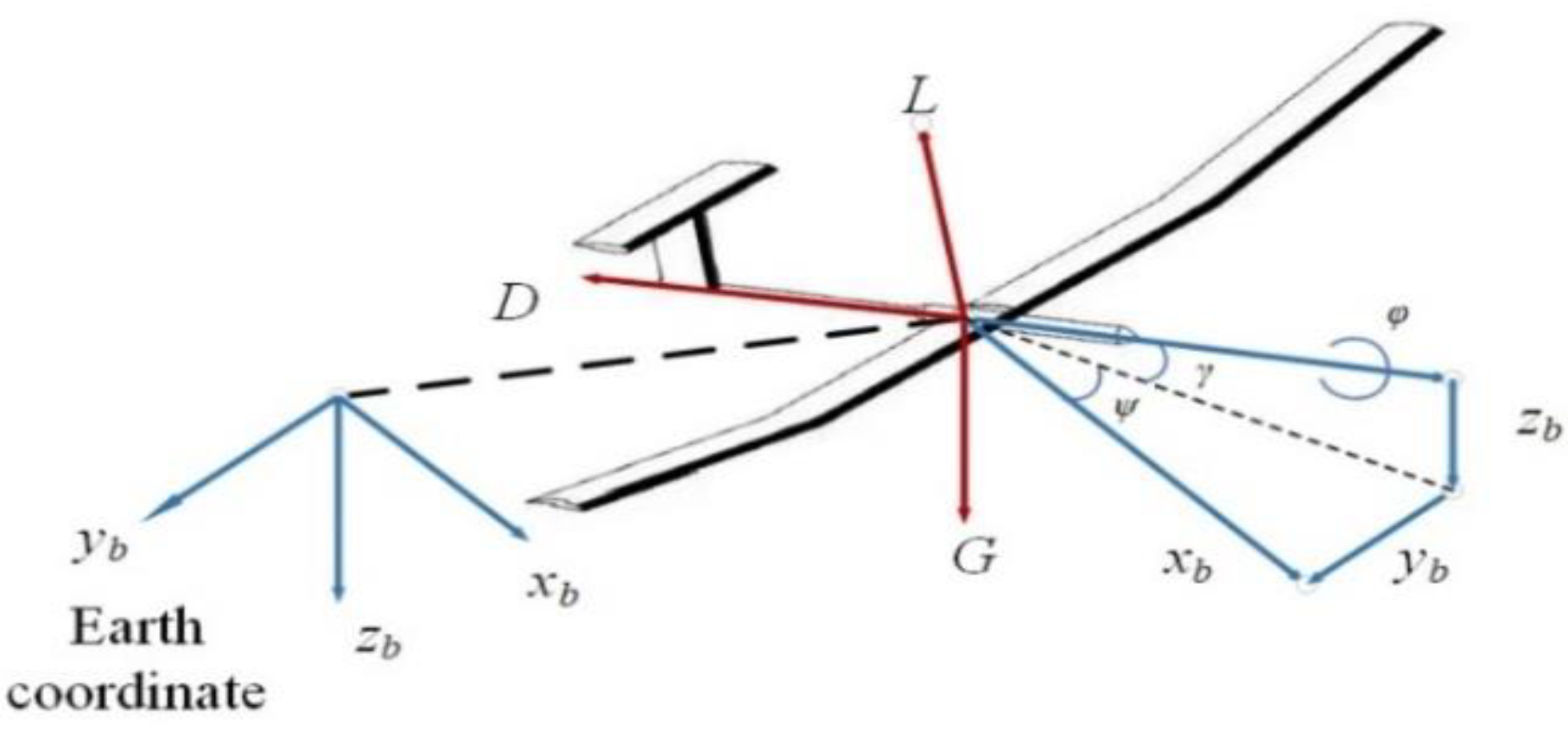
where x, y are the position of the SUAV, z is the altitude, subscript i indicates the parameters of the ith SUAV, V is the velocity, g is the gravitational acceleration, m is the mass, L is the lift, and ψ, γ, ϕ are the heading angle, flight path angle, and bank angle, respectively (see Figure 2). The thrust consumption is reduced to zero during the gliding process, and it is set to 10% of the cruise power when the SUAV soars through the thermal in this work. It is necessary to note that Euler angles, which define the attitude of the SUAV, may lead to singularities, and some articles have proposed solutions to address these problems [33]. However, the variations of the SUAV attitude is small during flight; there is typically no singularity problem when using Euler angles.

2.3. Solar Irradiance Model

One assumption of the solar model is that the flight environment of the SUAV is under a clear sky without any clouds. This condition meets the standard of the ASHRAE clear sky model [23]. The SUAV can acquire energy from sunlight and convert it into electric energy through the solar panel. The solar radiation could be computed according to the following steps based on the ASHRAE model. First, we compute the solar irradiance I (W/m2), which is perpendicular to the horizontal solar panel on the wing:
I = I 0 ( 1 + 0.034 cos 2 π n d a y 365.25 )
where I0 is the solar constant, nday is the number of days starting from 1 January in a year.
The atmosphere of the earth could absorb, diffuse, and radiate solar radiation, and the total solar irradiance on the earth’s horizontal surface are expressed as [23]:
I h = I b sin α e + I d I b = I e τ b m r b I d = I e τ d m r d b = 1.219 0.043 τ b 0.151 τ d 0.204 τ b τ d d = 0.202 + 0.852 τ b 0.007 τ d 0.357 τ b τ d m r = 1 sin α e
where Ih, Ib, Id are the beam, diffuse, and total irradiances on the earth’s horizontal surface, respectively; b and d are the beams and diffuse air mass exponents; τb and τd are the beams and diffuse optical depths; mr is the air mass ratio, and αe is the solar elevation angle.
The solar altitude angle αe and solar azimuth angle αz are variables under different solar times and latitudes with the following expression [23]:
sin α e = sin n l a t sin δ + cos n l a t cos δ cos ω ( t ) sin α z = cos δ cos ω ( t ) cos α e δ = 0.4093 sin ( 2 π ( 284 + n d a y ) 365 ) ω ( t ) = 0.2618 ( 12 t l o c a l )
where nlat is the latitude, δ is the declination angle of the sun, ω(t) is the hour of the sun, and tlocal is the current time of the day.
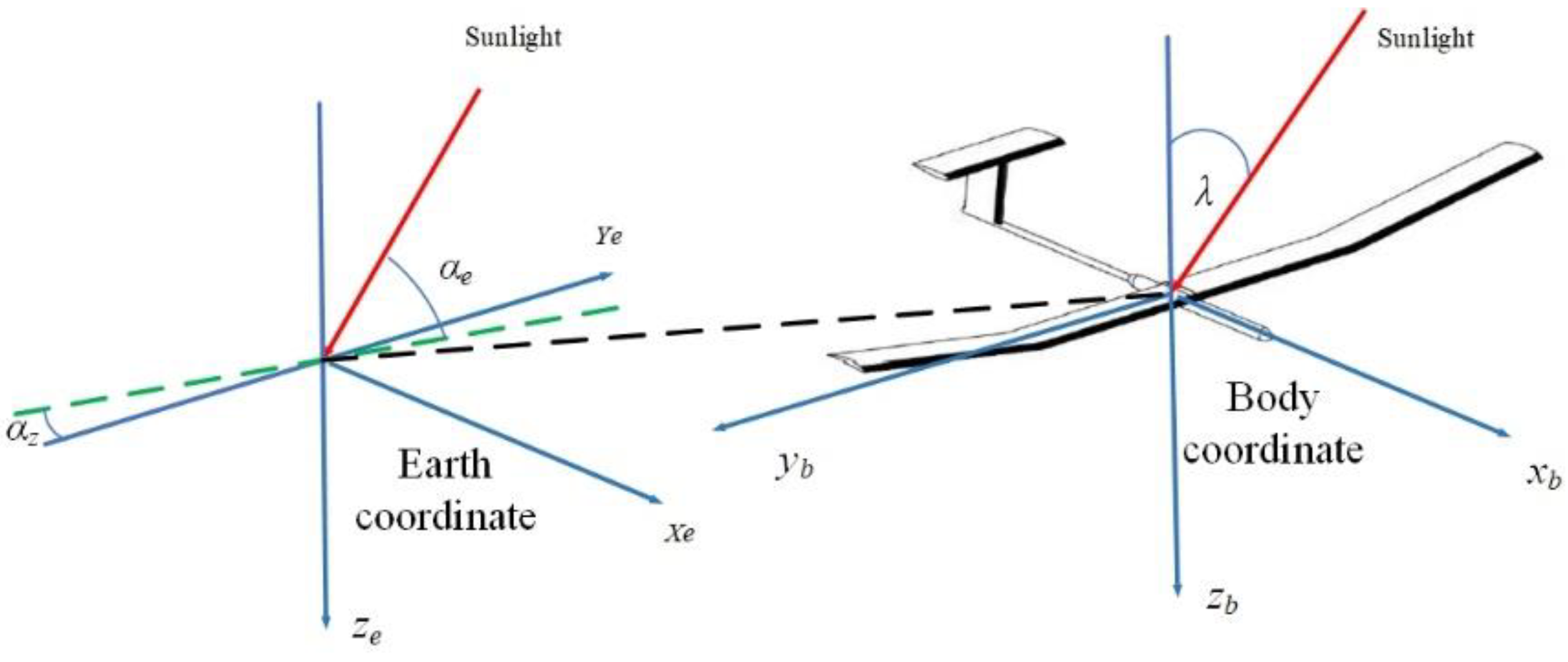
Then, the solar incident angle should be calculated in order to achieve the solar irradiance on the airfoil of the SUAV. Figure 3 present an earth coordinate frame, and a body-fixed coordinate frame is built, in which E, N, D point to the orientations of east, north, and ground, respectively. The unit vector of the sunlight Vp is defined under the earth’s coordinate frame:
V p = [ cos α e cos α z cos α e sin α z sin α e ]
In the body-fixed coordinate frame, the unit vector Vb along the reverse direction of the axis Obzb toward the ground could be expressed as:
V b = [ 0 0 1 ] T
Next, the vector Vp could be converted into the vector Vpb according to the principle of rotating coordinate transformation:
V p b = L x ( ϕ ) L y ( γ ) L z ( ψ ) [ cos α e cos α z cos α e sin α z sin α e ]
where Lx, Ly, Lz are the element rotation matrices. The flight path angle (or the pitch angle) is ignored in the function because it is small (less than 5 degrees) in the gliding and soaring phase.
Next, the incident angle λ is achieved according to Equations (5)–(8) above [25]:
cos λ = cos α e sin α z cos ψ sin ϕ cos α e cos α z sin ψ sin ϕ + sin α e cos ϕ

2.4. Energy Model of the SUAV

Once the incident angle and the SUAV attitude are obtained, the power generated by the solar cell could be calculated as [25]:
{ P b = { cos λ I b     if   cos λ 0 0    if   cos λ < 0 P d = I d cos 2 ϕ 2 P r = I h ρ r sin 2 ϕ 2 P i n = ( P b + P d + P r ) η s o l a r S s o l a r
where Pb, Pd, Pr are the beam irradiance, the diffuse irradiance, and the ground reflection irradiance on the airfoil, respectively. ρr is the ground reflection factor whose value is set to zero in this paper. Besides, Ssolar is the area of the solar panel, ηsolar is the conversion efficiency of the solar cell.
The thrust, drag, and power consumption associated with the dynamic model are express as [20]:
{ P o u t = T V η p r o p T = D = 1 2 ρ V 2 S C D C D = C D 0 + C L 2 ε π R a
We assume that the lift and gravity of the SUAV are in balance during the soaring and gliding phases in this work. And thus, the lift of the SUAV in flight is obtained as:
C L = 2 m g ρ V 2 S cos ϕ
where T is the thrust, ηprop is the propeller efficiency, D is the drag force, ρ is the air density, S is the area of the wing, CD is the drag coefficient, CD0 is the parasitic drag coefficient, ε is the Oswald efficiency factor, Ra is the aspect ratio of the wing.
The energy input Ein and energy output Eout of the SUAV during fight are ex-pressed as:
E i n ( t 0 , t f ) = t 0 t f P i n d t E o u t ( t 0 , t f ) = t 0 t f P o u t d t
where t0 and tf is the initial time and finish time of the flight, respectively. Finally, the total energy Etotal of the ith SUAV could be calculated as:
E t o t a l ( i ) = E i n ( i ) E o u t ( i )

3. Integrated Guidance and Control Process for Soaring

3.1. Total Energy and Autonomous Soaring Process

The perception of the thermal is necessary to achieve soaring for UAV. Nevertheless, the thermal character cannot be measured directly by any onboard sensor. The main factor for thermal detection and control during soaring is the rate of energy change of the UAV. Thus, the total potential and kinetic energy of the UAV is introduced and normalized for the weight m to obtain the specific energy E. The estimate of E is differentiated concerning time to obtain the specific energy rate E ˙ . Finally, the energy acceleration E ¨ is obtained after differentiation.
E = h + V 2 2 g
E ˙ = h ˙ + V V ˙ g
where h is the altitude, which is the same as z in the function. Finally, the energy acceleration E ¨ is obtained after differentiation.
The whole structure and process for autonomous soaring consists of thermal identification, guidance, control, and mode logic blocks [34]. The input of the system includes the velocity, thrust, altitude, and position of the UAV, while the output is the yaw rate as the turn control acts on the UAV to soar. In this work, the soaring radius is set to 30 m based on the UAV minimum turn rate radius.
In the thermal identification block, the historical flight data of the SUAV position and energy rate E ˙ are stored in a n × 3 matrix:
[ P x 1 P y 1 E ˙ 1 P x 2 P y 2 E ˙ 2 P x n P y 1 E ˙ n ]
where subscript n denotes the nth recorded historical data that could be used to estimate the thermal center. Several methods have been proposed for estimation, for example, weighted average, Gaussian regression, and Kalman filter. This work exploits the weighted average method since it can deal with the center of a drift thermal effectively:
P t h = [ i = 1 n P x i E ˙ i i = 1 n E ˙ i i = 1 n P y i E ˙ i i = 1 n E ˙ i ]

3.2. Control and Logic

Furthermore, referring to Ref. [32], a feedback control and a mode logic are introduced to guide the SUAV to soar around the thermal center once the UAV flies near it and switches to soaring mode. The SUAV will leave the thermal once it has climbed 100 m.
S = ( x x ^ t h ) 2 + ( y y ^ t h ) 2
ψ s o a r = V r
e p = r S
ψ ˙ = k 1 E ¨ s + k 2 e p + k 3 e ˙ p + ψ s o a r
where S is the distance between the SUAV and the predicted thermal center, r and ψsoar are the radius and heading angle during soaring, respectively, ep is the difference between r, and S. k1, k2, and k3 are the relative gains. ψ ˙ is the calculated yaw rate that commands the UAV to fly around the thermal center. Finally, the principle for deciding whether the SUAV switches to soaring mode is similar to Ref. [34].

4. Non-Cooperation and Cooperation Assignment Strategies

4.1. Non-Cooperative Competition Mode

The mission of SUAVs is to fly from different starting points to the same terminal while being able to soar by using the single thermal distributed throughout the flight. In addition, the issue of collision avoidance is a necessary concern for multiple SUAVs. A safe distance of at least 100 m between each aircraft is required. Yet, the soaring altitude of the SUAV using the thermal is exactly 100 m in this work. Concerning the mission time and safe distance, we suppose only one SUAV could soar through thermals during flight missions, while the other SUAVs must fly directly to the destinations.
The SUAV’s endurance could be increased by soaring and gliding. For each SUAV, the only goal is to soar through thermals and to compete with other UAVs for occupancy of the thermal regardless of the amount of electric power storage benefit from soaring. On the above deduction, there are two strategies for each UAV: one is to use the thermal for soaring and subsequently fly towards the terminal point; the other is to reach the destination directly in case the thermals are occupied by other SUAVs.
Based on the analysis, it is possible to establish the objective function of the problem as follows:
max x 1
max x 2
max x 3
Equations (23)–(25), respectively, represent the objective functions for the first SUAV, the second SUAV, and the third SUAV under the mode of non-cooperative competition for thermal assignment, where xi denotes whether the ith UAV is assigned to the thermal. When xi = 0 it means that the ith UAV does not use the thermal to soar, while when xi = 1 it means that the ith UAV could soar through the thermal.
Considering the different velocities of the three SUAVs, the relative distance between each SUAV to the thermal is not the same, and the SUAV with the shortest time to reach the thermal can preemptively employ the thermals, while the other SUAVs have to give up soaring and fly towards the destination. Therefore, the three objective functions would be combined into the one expressed as follows:
min x 1 t 1 + x 2 t 2 + x 3 t 3
where ti denotes the time cost that ith SUAV reaches the thermal whose value could be calculated as:
t 1 = D 1 V 1 , t 2 = D 2 V 2 , t 3 = D 3 V 3
where Di denotes the distance between the ith SUAV and the thermals. The significance of this objective function is the first SUAV arriving at the thermal could use it to soar and subsequently glide towards the destination, whereas the other SUAVs which are not assigned the thermal have to fly toward the destination directly. In other words, the utilization of the thermal by the SUAV is determined by the time it takes for the SUAV to reach the thermal.
The objective function (Equation (26)) shows that the allocation of the thermal in competition mode is contingent on the time at which the UAV reaches the updraft (Equation (27)). When all three arrival times are identical, theoretically, any SUAV could soar through the thermal, which can be considered the “equilibrium point” or “critical point” in the competition. Given that the velocities of the three SUAVs are known and constant, the equilibrium time can be expressed as:
D 1 9 = D 2 11 = D 3 13
In the competition mode, if the time or distance traveled by one SUAV is less than the equilibrium value compared to the other vehicles, that specific SUAV can secure access to the thermal updraft for soaring.
The constraints of the problem are expressed as:
s . t o x 1 + x 2 + x 3 = 1 x 1 { 0 , 1 } x 2 { 0 , 1 } x 3 { 0 , 1 }
The constraint indicates that the sum of the thermal shared by the three SUAVs is 1, i.e., just one SUAV could soar with thermal. In the non-cooperative competition problem, the strategy choice of a SUAV affects the strategies of the other UAVs.
Combining the objective function and constraints of the problem, the conclusion can be drawn that for the non-cooperative competition problem in the context of soaring with the thermal, each SUAV only considers whether the use of the thermal is advantageous in improving its endurance and whether it can reach the thermal before the other SUAVs, regardless of the charging condition by the soaring of the other UAVs, and even the overall energy gain of the UAV group. Since the objective function and constraints are linear, the problem can be solved by traditional linear programming methods.

4.2. Cooperative Assignment Mode

For the SUAV group, the most important goal is to elevate the sum of the stored electric energy of the SUAVs rather than the energy of a specific one. Therefore, a cooperative approach should be introduced by reserving the thermal for the SUAV so that the overall energy gain of the multiple SUAVs from soaring is the maximum when they reach the destination. Based on the analysis above, the objective function of the thermal cooperative allocation problem for the multiple SUAVs is obtained as follows:
max x 1 c 1 + x 2 c 2 + x 3 c 3
where ci denotes the energy gain coefficient for the case where the ith SUAV soars through the thermal. The constraint of the objective function is:
s . t o x 1 + x 2 + x 3 = 1 x 1 { 0 , 1 } x 2 { 0 , 1 } x 3 { 0 , 1 }
The constraint indicates that the sum of the thermal shared by the three SUAVs is 1, i.e., only one SUAV can share the thermals.
As part of the SUAVs fail to use the thermal for soaring, the energy cost coefficients need to be calculated not only for the amount of electricity gained by the SUAVs with soaring but also to estimate the difference in the electrical energy storage between the two modes: whether SUAVs use the thermals for soaring or not. The process of the cost coefficient calculation in the objective function is:
T 1 = 100 ω , T 2 = D g V i , T 3 = D i j D g V
E i n = P i n T 1 + P i n ( T 2 + T 3 ) E o u t = P o u t T 1 + P o u t T 3
c i = E i n i j E o u t i j
Once the energy cost coefficient is obtained, the objective function Equation (30) and the constraints Equation (31) are both linear. Thus, the problem can be solved by a linear programming approach.
Combining Equations (29) and (31) shows the constraints are the same under the non-cooperative competition problem and cooperative allocation. Therefore, it comes to the conclusion that for the multiple SUAVs and single thermal allocation problem, the external environmental variables (e.g., the number of SUAVs and thermals) determine the constraints, while the form and formulation of the objective function depend on whether the optimization objective focuses more on individual or collective gains.

5. Simulation and Results

This section provides a series of numerical simulations to validate the allocation results and energy performance for multiple SUAVs during soaring. In this work, we consider the scenario in Beijing (39.93° N, 116.28° E) at 16:00 on 1 March. To eliminate the influence of different altitudes on soaring and gliding time, the soaring altitude is limited to 100 m. The initial altitude of the SUAVs is 500 m, and the SUAVs will leave the thermal at the altitude of 600 m. Referring to Ref. [14], the parameters of the SUAV are listed in Table 1.
The motion of the SUAV includes the cruise phase, gliding phase, and soaring phase. In this paper, the thrust is zero when the SUAV is in the soaring and gliding phases. Assume that the three SUAVs have different initial positions, while the destination is (0, 1800). Each UAV flies at a constant velocity, but each SUAV has a different velocity. The position of the thermal can be set arbitrarily due to randomness, assuming that the thermal is located at (−300, 300), (0, 200), and (300, 300), respectively. The initial parameters of the SUAV are listed in Table 2.
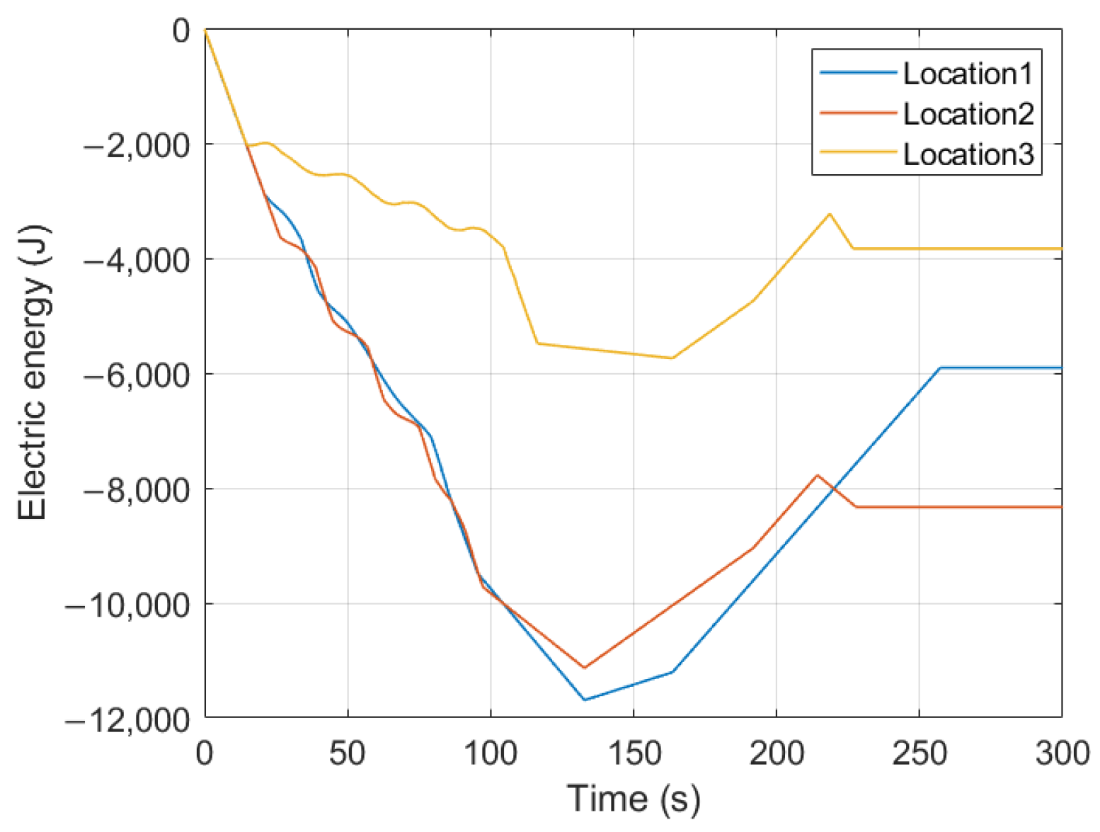
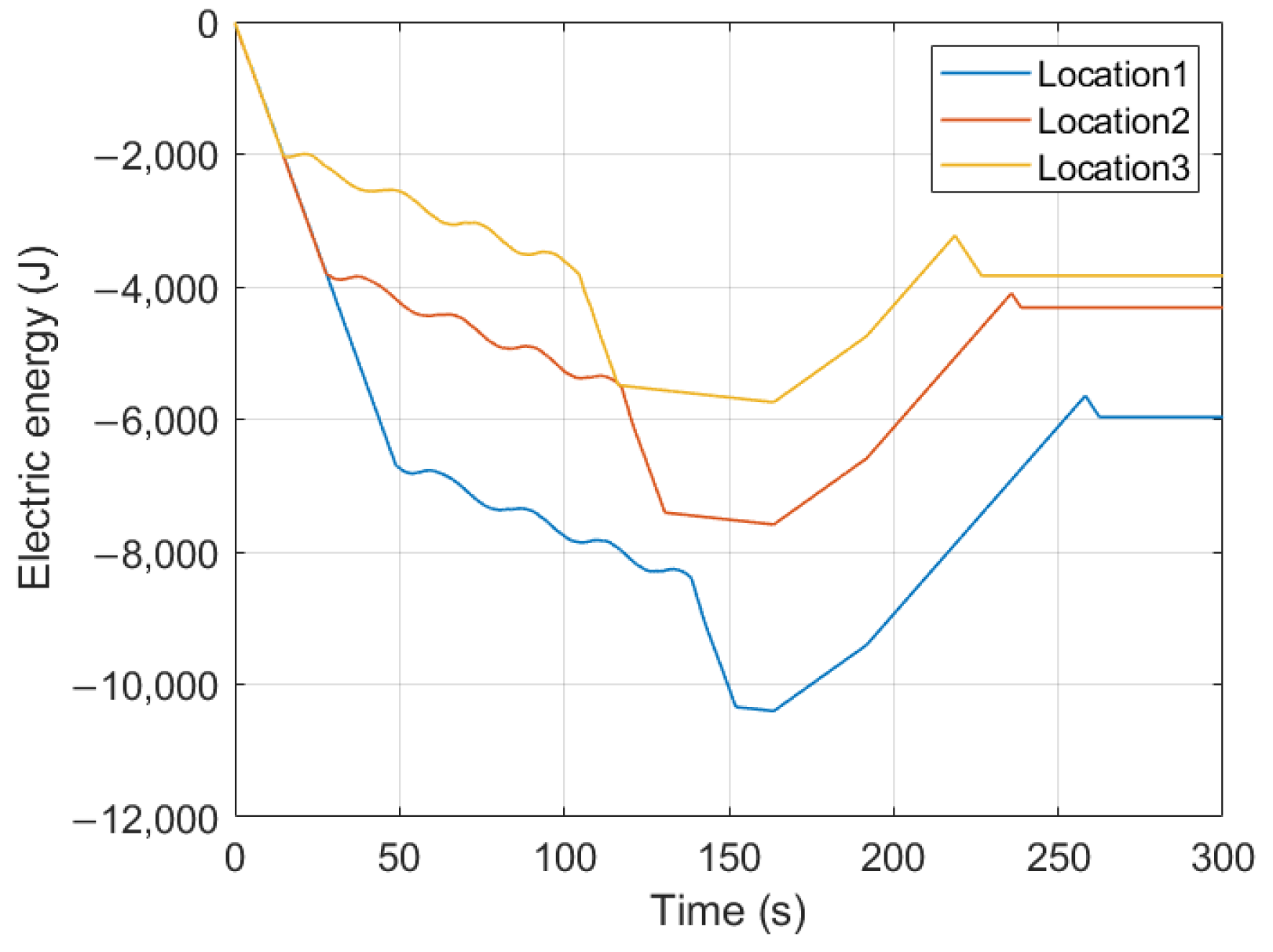
The data presented in Figure 4 illustrate the impact of varying velocities on the energy performance of the SUAV when soaring through thermal. The results are conclusive, showcasing how the SUAV can significantly enhance its endurance by utilizing thermal updrafts as opposed to a direct flight path. Furthermore, the soaring will markedly benefit the SUAV even if the energy consumption is greater [14].

5.1. Non-Cooperative Competition Mode

The competition results of the thermal under non-cooperative mode can be obtained by solving the objective function (Equation (26)) under constraint (Equation (29)), as shown in Table 3:
Figure 5, Figure 6 and Figure 7 present the flight trajectories and electric energy storage of the three SUAVs based on the non-cooperative competition results with different thermal locations. After the UAV that first reaches the thermal chooses the strategy of using the thermal, the strategy of the rest of the SUAVs is to fly directly to the endpoint. Since the flight time is determined by the relative distance between the SUAVs and the thermals, the thermal’s initial position has an influence on all the strategy selection of the SUAVs.
As can be seen in Figure 8, if the third UAV would reach the thermal first, the overall energy of the SUAV team would be the optimum, otherwise, it could only improve the endurance of the SUAV that reaches the thermal first.

5.2. Cooperative Assignment Mode

The simulation uses the same velocity, initial position, and thermal position for all three SUAVs as listed in Table 2 and Table 3. The energy cost coefficients are calculated through Equations (32)–(34) and the objective function is solved to obtain the allocation strategy, the assignment result is shown in Table 4
Figure 9, Figure 10 and Figure 11 show the flight trajectories and electrical energy storage of the three SUAVs based on the allocation result for different thermal locations. The results suggest that no matter where the thermal is, the third SUAV could obtain the greatest energy gain by soaring through the thermal. Hence those multiple SUAVs always leave the thermal to the third SUAV under the cooperative condition to maximize the overall energy gain of the group.
On the other hand, even if the thermal location does not affect the multiple SUAVs’ allocation result of the thermal in the cooperative mode, a longer distance will lead to more energy consumption on the third SUAV due to the different distances between the SUAVs and the thermal. Consequently, the thermal location has a lesser impact on the sum of the electrical energy storage of the SUAVs under the cooperative allocation, as shown in Figure 12.
Finally, in comparing the results of multiple SUAVs’ selection of strategy and allocation of the thermal under the two conditions. It is clear that each SUAV in the non-cooperative mode only considers maximizing its own energy gain from the thermal, instead of that of the SUAV group. In contrast, the only criteria for each UAV’s selection of strategy in the cooperative mode is to enhance the energy benefit of the SUAV group from the thermal as much as possible.

6. Conclusions

This work examines the competition and allocation of a single thermal and energy variation for multiple SUAVs during the flight before they reach the destination. For comparing the decision-making results, this work considers two conditions of non-cooperative competition and cooperation modes between multiple SUAVs for the thermal. The corresponding objective functions and constraints are established for the two modes. The allocation results that are combined with the actual dynamics model and guidance control are verified by numerical simulation.
The simulation results show that the allocation strategy for multiple SUAVs under the non-cooperative mode depends on the time that each UAV takes to reach the thermal because the endurance of each SUAV can be increased evidently by soaring. However, the location of the thermal will determine the allocation result, so the overall electric energy storage of the SUAV group under the competition result may not be the maximum. When operating in cooperative mode, the selection strategy for targets among multiple UAVs remains consistent, regardless of the thermal location. The group of SUAVs assigns the thermal to the one that can achieve the highest energy gain through soaring, ultimately increasing the overall energy of the collective. The thermal location only impacts the amount of the group’s overall stored electrical energy.
While this work focuses on simulating a single thermal, in reality, there are typically multiple thermals distributed across a region, as outlined in the introduction. Thus, it becomes essential to establish the relevant objective functions for allocation problems involving multiple SUAVs and thermals in future work. Furthermore, although this study assumes explicit knowledge of the thermal properties, the actual location of thermals may often be uncertain or unknown. To address this, alternative techniques like fuzzy logic or similar approaches could be introduced to cope with the uncertainty thermal parameters. Finally, there is the potential to explore more intricate gain coefficients through innovative game models to investigate the competition among multiple UAVs for unknown thermals.

Author Contributions

Conceptualization, Y.W. and K.L.; methodology, Y.W., K.L. and S.W.; software, Y.W., Y.L. and X.C.; validation, Y.W., A.Z. and S.W.; formal analysis, Y.W., A.Z. and Y.L.; investigation, Y.W. and S.W.; resources, K.L.; data curation, Y.W., A.Z. and Y.L.; writing—original draft preparation, Y.W. and X.C.; writing—review and editing, K.L.; visualization, Y.W.; supervision, K.L.; project administration, K.L.; funding acquisition, K.L. All authors have read and agreed to the published version of the manuscript.

Funding

This work is supported by the National Natural Science Foundation of China (No. 61773039) and Aeronautical Science Foundation of China (No. 2017X51018).

Data Availability Statement

Not applicable.

Conflicts of Interest

The authors declare no conflict of interest.

References

  1. Lun, Y.B.; Yao, P.; Wang, Y.X. Trajectory Optimization of SUAV for Marine Vessels Communication Relay Mission. IEEE Syst. J. 2020, 14, 5014–5024. [Google Scholar] [CrossRef]
  2. Hu, S.Y.; Ni, W.; Wang, X.; Jamalipour, A. Disguised Tailing and Video Surveillance with Solar-Powered Fixed-Wing Un-manned Aerial Vehicle. IEEE Trans. Veh. Technol. 2022, 71, 5507–5518. [Google Scholar] [CrossRef]
  3. Huang, H.L.; Savkin, A.V. Energy-efficient decentralized navigation of a team of solar-powered UAVs for collaborative eavesdropping on a mobile ground target in urban environments. Ad Hoc Netw. 2021, 117, 102485. [Google Scholar] [CrossRef]
  4. Bencate, R.; deSousa, J.T.; Girard, A. Atmospheric flow field models applicable for aircraft endurance extension. Prog. Aerosp. Sci. 2013, 61, 1–25. [Google Scholar] [CrossRef]
  5. Akos, Z.; Nagy, M.; Leven, S.; Vicsek, T. Thermal soaring flight of birds and unmanned aerial vehicles. Bioinspir. Biomim. 2010, 5, 045003. [Google Scholar] [CrossRef]
  6. Allen, M. Updraft Model for Development of Autonomous Soaring Uninhabited Air Vehicles. In Proceedings of the 44th AIAA Aerospace Sciences Meeting and Exhibit, Reno, NV, USA, 6–12 January 2006. [Google Scholar]
  7. Walton, C.; Kaminer, I. Alternate Strategies for Optimal Unmanned Aerial Vehicle Thermaling. J. Aircraft 2018, 55, 2347–2356. [Google Scholar] [CrossRef]
  8. Andersson, K.; Kaminer, I.; Dobrokhodov, V.; Cichella, V. Thermal Centering Control for Autonomous Soaring: Stability Analysis and Flight Test Results. J. Guid. Control Dyn. 2012, 25, 963–975. [Google Scholar] [CrossRef]
  9. Notter, S.; Gross, P.; Schrapel, P.; Fichte, W. Multiple Thermal Updraft Estimation and Observability Analysis. J. Guid. Control Dyn. 2020, 43, 490–503. [Google Scholar] [CrossRef]
  10. Notter, S.; Schimpf, F.; Muller, G.; Fichter, W. Hierarchical Reinforcement Learning Approach for Autonomous Cross-Country Soaring. J. Guid. Control Dyn. 2022, 46, 114–126. [Google Scholar] [CrossRef]
  11. Rosales, J.; Gross, A. Statistical Analysis of Autonomous Soaring Algorithm. J. Guid. Control Dyn. 2022, 45, 2398–2402. [Google Scholar] [CrossRef]
  12. Khaghani, J.; Nekoui, M.; Nasiri, R.; Ahmadabadi, M.N. Analytical Model of Thermal Soaring: Towards Energy Efficient Path Planning for Flying Robots. In Proceedings of the 2018 IEEE/RSJ International Conference on Intelligent Robots and Systems, Madrid, Spain, 1–5 October 2018. [Google Scholar]
  13. Tin, F.E.; Borowczyk, A.; Sharf, I.; Nahon, M. Turn Decisions for Autonomous Thermalling of Unmanned Aerial Gliders. J. Intell. Robot. Syst. 2022, 104, 1–18. [Google Scholar] [CrossRef]
  14. Wu, Y.; Li, K.; Zhao, A.; Liu, H.; Li, Y.; Wen, D. Energy Analysis for Solar-Powered Unmanned Aerial Vehicle under Static Soaring. Aerospace 2023, 10, 779. [Google Scholar] [CrossRef]
  15. Oettershagen, P.; Stastny, T.; Hinzmann, T.; Rudin, K.; Mantel, T.; Melzer, A.; Wawrzacz, B.; Hitz, G.; Siegwart, R. Robotic technologies for solar-powered UAVs: Fully autonomous updraft-aware aerial sensing for multiday search-and-rescue missions. J. Field Robot. 2018, 35, 612–640. [Google Scholar] [CrossRef]
  16. Edwards, D.J.; Kahn, A.D.; Kelly, M.; Heinzen, S.; Scheiman, D.A.; Jenkins, P.P.; Walters, R.; Hoheisel, R. Maximizing net power in circular turns for solar and autonomous soaring aircraft. J. Aircraft 2016, 53, 1237–1247. [Google Scholar] [CrossRef]
  17. Mateja, K.; Skarka, W.; Peciak, M.; Niestrój, R.; Gude, M. Energy Autonomy Simulation Model of Solar Powered UAV. Energies 2023, 16, 479. [Google Scholar] [CrossRef]
  18. Li, K.; Wu, Y.; Bakar, A.; Wang, S.; Li, Y.; Wen, D. Energy System Optimization and Simulation for Low-Altitude So-lar-Powered Unmanned Aerial Vehicles. Aerospace 2022, 9, 331. [Google Scholar] [CrossRef]
  19. Wu, J.F.; Wang, H.L.; Huang, Y.; Zhang, M.H.; Su, Z.K. Solar-Powered Aircraft Endurance Map. J. Guid. Control Dyn. 2019, 42, 687–694. [Google Scholar] [CrossRef]
  20. Huang, Y.; Wang, H.L.; Yao, P. Energy-optimal path planning for Solar-powered UAV with tracking moving ground target. Aerosp. Sci. Technol. 2016, 53, 241–251. [Google Scholar] [CrossRef]
  21. Huang, Y.; Chen, J.G.; Wang, H.L.; Su, G.F. A method of 3D path planning for solar-powered UAV with fixed target and solar tracking. Aerosp. Sci. Technol. 2019, 92, 831–838. [Google Scholar] [CrossRef]
  22. Hosseini, S.; Mesbahi, M. Energy-Aware Aerial Surveillance for a Long-Endurance Solar-Powered Unmanned Aerial Vehicles. J. Guid. Control Dyn. 2016, 39, 1980–1993. [Google Scholar] [CrossRef]
  23. Xin, W.; Yao, P.; Xie, Z. Comprehensive optimization of energy storage and standoff tracking for solar-powered UAV. IEEE Syst. J. 2020, 14, 5133–5143. [Google Scholar]
  24. Wu, J.F.; Wang, H.L.; Li, N.; Yao, P.; Huang, Y.; Yang, H.M. Path planning for solar-powered UAV in urban environment. Neurocomputing 2018, 275, 2055–2065. [Google Scholar] [CrossRef]
  25. Wu, J.; Wang, H.; Li, N.; Yao, P.; Huang, Y.; Su, Z.; Yu, Y. Distributed trajectory optimization for multiple solar-powered UAVs target tracking in urban environment by Adaptive Grasshopper Optimization Algorithm. Aerosp. Sci. Technol. 2017, 70, 497–510. [Google Scholar] [CrossRef]
  26. Le, W.X.; Xue, Z.T.; Chen, J.; Zhang, Z.C. Coverage Path Planning Based on the Optimization Strategy of Multiple Solar Powered Unmanned Aerial Vehicles. Drones 2022, 6, 203. [Google Scholar] [CrossRef]
  27. Lun, Y.B.; Wang, H.L.; Wu, J.F.; Liu, Y.H.; Wang, Y.X. Target Search in Dynamic Environments with Multiple Solar-Powered UAVs. IEEE Trans. Veh. Technol. 2022, 71, 9309–9321. [Google Scholar] [CrossRef]
  28. Andersson, K.; Kaminer, I.; Jones, K.; Dobrokhodov, V.; Lee, D.J. Cooperating UAVs Using Thermal Lift to Extend Endurance. In Proceedings of the AIAA Infotech@Aerospace Conference, Seattle, WA, USA, 6–9 April 2009. [Google Scholar]
  29. Antal, C.; Granichin, O.; Levi, S. Adaptive Autonomous Soaring of Multiple UAVs Using Simultaneous Perturbation Stochastic Approximation. In Proceedings of the 49th IEEE Conference on Decision and Control, Atlanta, GA, USA, 15–17 December 2010. [Google Scholar]
  30. Cobano, J.A.; Alejo, D.; Vera, S.; Heredia, G.; Ollero, A. Multiple gliding UAV coordination for static soaring in real time applications. In Proceedings of the 2013 IEEE International Conference on Robotics and Automation, Karlsruhe, Germany, 6–10 May 2013. [Google Scholar]
  31. Acevedo, J.; Lawrance, N.R.; Arrue, B.C.; Sukkarieh, S.; Ollero, A. Persistent monitoring with a team of autonomous gliders using static soaring. In Proceedings of the 2014 IEEE/RSJ International Conference on Intelligent Robots and Systems, Chicago, IL, USA, 14–18 September 2014; pp. 4842–4848. [Google Scholar]
  32. Cobano, J.A.; Alejo, D.; Vera, S.; Sukkarieh, S.; Heredia, G.; Ollero, A. Thermal detection and generation of collision-free trajectories for cooperative soaring UAVs. In Proceedings of the IEEE/RSJ International Conference on Intelligent Robots and Systems, Karlsruhe, Germany, 6–10 May 2013. [Google Scholar]
  33. Yu, Y.; Ding, X.A. Global Tracking Controller for Underactuated Aerial Vehicles: Design, Analysis, and Experimental Tests on Quadrotor. IEEE ASME Trans. Mechatronics 2016, 21, 2499–2511. [Google Scholar] [CrossRef]
  34. Allen, M.; Lin, V.; Samuel, T. Guidance and Control of an Autonomous Soaring Vehicle with Flight Test Results. In Proceedings of the 45th AIAA Aerospace Sciences Meeting and Exhibit, Reno, NV, USA, 8–11 January 2007. [Google Scholar]
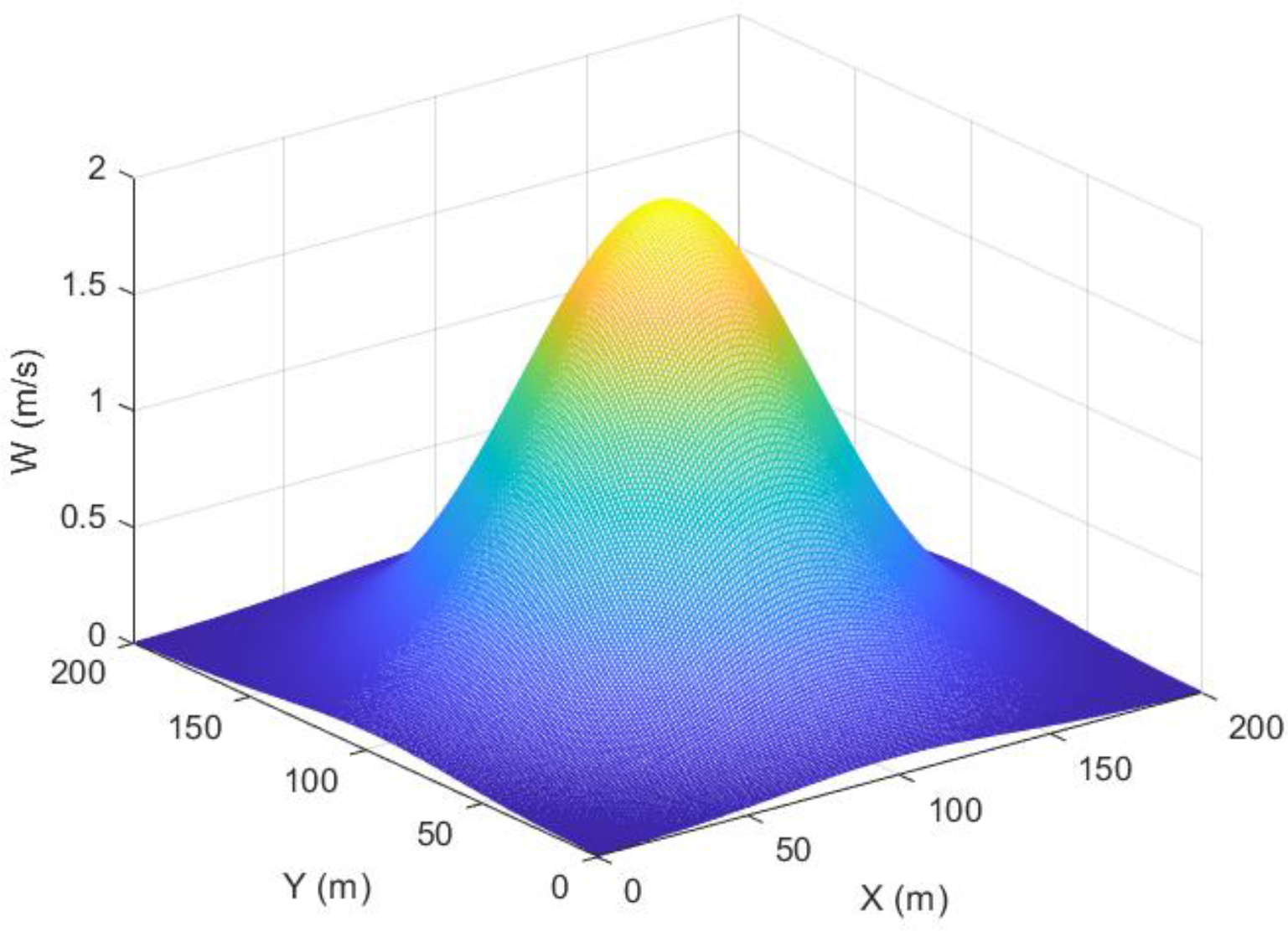
Figure 1. Thermal updraft model for Wmax = 2 m/s, R = 55 m.
Drones 07 00653 g001
Figure 2. Forces and Euler angles for the SUAV [14].
Drones 07 00653 g002
Figure 3. Solar incidence angle on the SUAV [14].
Drones 07 00653 g003
Figure 4. The SUAV electric energy storage with or without soaring under different velocities: (a) V = 9 m/s, (b) V = 11 m/s, (c) V = 13 m/s [14].
Drones 07 00653 g004
Figure 5. The SUAVs status under non-cooperative mode, thermal location (−300, 300): (a) 3D space, (b) xy plane, (c) stored electric energy.
Drones 07 00653 g005
Figure 6. The SUAVs status under non-cooperative mode, thermal location (0, 200) (a) 3D space (b) xy plane (c) stored electric energy.
Drones 07 00653 g006
Figure 7. The SUAVs status under non-cooperative mode, thermal location (300, 300) (a) 3D space (b) xy plane (c) stored electric energy.
Drones 07 00653 g007
Figure 8. The stored electric energy in total of the three SUAVs under non-cooperative mode for different thermal locations.
Drones 07 00653 g008
Figure 9. The SUAVs status under cooperative mode, thermal location (−300, 300) (a) 3D space (b) xy plane (c) stored electric energy.
Drones 07 00653 g009
Figure 10. The SUAVs status under cooperative mode, thermal location (0, 200) (a) 3D space (b) xy plane (c) stored electric energy.
Drones 07 00653 g010
Figure 11. The SUAVs status under cooperative mode, thermal location (300, 300) (a) 3D space (b) xy plane (c) stored electric energy.
Drones 07 00653 g011
Figure 12. The stored electric energy in total of the three SUAVs under cooperation mode for different thermal locations.
Drones 07 00653 g012
Table 1. Parameters of the SUAV.
SignParameterValueUnit
I0Solar irradiance1367W/m2
τbBeam optical depths0.626N/A
τdDiffuse optical depths1.707N/A
SsolarSolar cell area1.37m2
SWing area1.75m2
mMass6.93kg
ρAir density1.26kg/m3
CD0Parasitic drag0.025N/A
εOswald efficiency factor0.92N/A
RaAspect ratio of the wing18.5N/A
ηpropPropeller efficiency60%N/A
ηsolarSolar cell efficiency22%N/A
Table 2. Conditions of the three SUAVs.
SUAV1SUAV2SUAV3
Initial position(−300, 100)(0, 0)(300, 100)
Velocity 9 m/s11 m/s13 m/s
Table 3. Allocation results for different thermal locations under the non-cooperative mode.
Thermal LocationsAssignment Result
(−300, 300)SUAV1
(0, 300)SUAV2
(300, 300)SUAV3
Table 4. Allocation results for different thermal locations under the cooperative assignment mode.
Thermal LocationsAssignment Result
(−300, 300)SUAV3
(0, 300)SUAV3
(300, 300)SUAV3
Disclaimer/Publisher’s Note: The statements, opinions and data contained in all publications are solely those of the individual author(s) and contributor(s) and not of MDPI and/or the editor(s). MDPI and/or the editor(s) disclaim responsibility for any injury to people or property resulting from any ideas, methods, instructions or products referred to in the content.