Article

Assessment of Indiana Unmanned Aerial System Crash Scene Mapping Program

1
Joint Transportation Research Program, Purdue University, West Lafayette, IN 47907, USA
2
Tippecanoe County Sheriff’s Office, 2640 Duncan Road, Lafayette, IN 47904, USA
*
Author to whom correspondence should be addressed.
Drones 2022, 6(9), 259; https://doi.org/10.3390/drones6090259
Submission received: 7 August 2022 / Revised: 5 September 2022 / Accepted: 14 September 2022 / Published: 17 September 2022

Abstract

:
Many public safety agencies in the US have initiated a UAS-based procedure to document and map crash scenes. In addition to significantly reducing the time taken to document evidence as well as ensuring first responder safety, UAS-based mapping reduces incident clearance time and thus the likelihood of a secondary crash occurrence. There is a wide range of cameras used on these missions, but they are predominantly captured by mid-priced drones that cost in the range of $2000 to $4000. Indiana has developed a centralized processing center at Purdue University that has processed 252 crash scenes, mapped using 29 unique cameras, from 35 public agencies over the past three years. This paper includes a detailed case study that compares measurements obtained from a traditional ground-based real-time kinematic positioning base station and UAS-based photogrammetric mapping. The case study showed that UAS derived scale errors were within 0.1 ft (3 cm) of field measurements, a generally accepted threshold for public safety use cases. Further assessment was done on the 252 scenes using ground control scale error as the evaluation metric. To date, over 85% of the measurement errors were found to be within 0.1 ft (3 cm). When substantial errors are identified by the Purdue processing center, they are flagged for further dialog with the agency. In most of the cases with larger errors, the ground control distance was incorrectly measured, which is easily correctable by returning to the scene and performing new distance control measurements.

1. Introduction

The use of Unmanned Aerial Systems (UAS) for photogrammetric applications is gaining momentum at a rapid pace. UAS provide a safe and efficient method for photogrammetric mapping while still providing accurate results for a number of use cases including surveying, inspection and mapping in a wide variety of domains including agriculture, forestry, construction and coastal mapping among others [1,2,3,4]. The application of UAS in crash scene mapping allows public safety agencies to quickly document crash scenes and clear an incident, resulting in reduced road closure times and, subsequently, a reduced likelihood of secondary crashes. This paper reports on the state of a UAS-based crash scene mapping program in the state of Indiana led by the Indiana Criminal Justice Institute. Insights on the accuracy and length of scale markers, camera types from more than 250 crash scenes alongside a comparison with terrestrial measurements are presented in this study.
The text that follows provides a brief review of existing and commonly used measurement techniques for crash scene investigation and documentation from the perspectives of time efficiency, measurement accuracy, and cost-effectiveness.

1.1. Affordability

Although UAS were first introduced for military applications, consumer drone manufacturers have more recently begun to offer units that are smaller in footprint at an affordable price which can be conveniently deployed for transportation engineering applications. Methodological frontier and future research directions were comprehensively discussed in several reviews [5,6]. In addition to research interests, several state Department of Transportations (DOT) widely explored the cost-effectiveness of practical applications of UAS in solving real-world transportation problems. The use of UAS in traffic surveillance and traffic management has been initially evaluated by Ohio DOT [7], Florida DOT [8] and Washington DOT [9]. Integration of UAS in roadway construction activities has been qualitatively examined by Georgia DOT [10,11]. Leveraging UAS with highway infrastructure management especially for bridge deck inspection has been investigated by Minnesota DOT [12] and South Dakota DOT [13]. Such feasibility analyses demonstrates that low-cost commercial UAS have attracted attention in the transportation area, and affordability is not a significant cost barrier [5,6].

1.2. Public Safety Implementation

According to the Federal Highway Administration [14], the likelihood of a secondary crash increases by 2.8% for each minute a primary crash is not cleared, which requires an effective post-crash documentation in addition to quick clearance of the cumulative queue at the crash scene. UAS has been extensively adopted by public safety agencies in the United States to capture high-resolution images during crash scene investigation. In Indiana, two of the early adopting agencies mapped more than 50 crash scenes using UAS over a two year period [15]. The time taken to document crash investigation evidence was found to be reduced to 15–20 min, which significantly reduces the likelihood of a secondary crash.
Although public safety agencies have deployed UAS in the image acquisition stage of crash scene mapping, image processing including 3D reconstruction, point cloud generation, and model optimization has been conducted at a limited scale [16,17]. The large-scale implementation of UAS crash scene mapping is still a challenge due to the cost of processing software and staff trained on photogrammetric processing and troubleshooting for the encountered problems [6]. Consequently, some public safety agencies have engaged in collaborations with research institutes equipped with photogrammetric expertise [18], where the public safety agency follows a standardized field data collection protocol, and the lab performs the photogrammetric work and returns a scaled ortho-rectified image mosaic. This centralized image processing framework in UAS-based crash scene mapping provides a consistent and scalable framework for processing and providing independent checks.

1.3. 2-Dimensional Measuring Techniques

Basic tape measurements have been used for decades to investigate and document traffic crashes. The procedure often requires multiple people to capture the measurements in addition to some form of temporary traffic control for cross-lane measurements. Depending on the magnitude of the crash, the time to collect effective scaled measurements ranges from 45 min to several hours. To reduce data acquisition time for on-site measurements, electronic total stations were utilized for crash scene investigations [19,20]. With total stations, the time to collect scale measurements decreased by 33% [20], and the average time-saving was estimated to be 51 min compared to adhesive tape measurements [19]. Moreover, the increase in the number of measurements led to a more accurate and detailed investigation and crash reconstruction than typically obtained with the coordinate procedure [20].

1.4. 3-Dimensional Measuring Techniques

Even though both measuring tapes and electronic total stations can provide detailed two-dimensional (2D) measurements, three-dimensional (3D) documentation of traffic crashes cannot be obtained from traditional 2D measuring tools. The emergence of terrestrial laser scanning (TLS) has enabled investigators to observe the type of entity damage and analyze contributing factors such as vehicle dynamics using a processed 3D digital model [21,22,23]. Given the large amount of data gathered, the speed of data acquisition was considered fast using TLS. And, the 3D point cloud derived from TLS can be registered via additional 2D scale markers, which ensured the accuracy of measurements [24].
Another prevailing surveying technique for 3D reconstruction of crash scenes is the use of close-range photogrammetry (CRP) and Structure-from-Motion (SfM) algorithms. Initially, terrestrial photogrammetry was proposed to capture high-resolution images after the occurrence of traffic crashes [25,26,27]. Compared to TLS, 3D photogrammetry from terrestrial images provided more visual cues for post-crash investigation where vehicle deformation, vehicle dynamics, and trajectory decomposition can be derived [26]. Additionally, with computer-aided surveying software, 3D crash reconstruction derived from terrestrial images can be achieved at centimeter-level accuracy on large scenes whereas multiple measurements would be required for traditional measurements [25]. Recent advances in virtual reality (VR) have also been tested and evaluated for crash scene reconstruction [28]. Subject vehicles and pedestrians can be matched in 3D space using video recordings from crash locations, and a 3D reconstruction of crash scenes has been generated by integrating terrestrial images and VR. Experimental results indicated that on comparison with traditional measuring tools, the VR technology required less time and showed acceptable levels of accuracy. Another branch of CRP study applied UAS-based photogrammetric mapping techniques due to the cost-effectiveness of UAS [18,29,30,31]. Using UAS, the time taken to document crash investigation evidence is 15 to 20 min, which is significantly shorter than the time for crash documentation via terrestrial images, and the UAS derived scale errors were within 0.4% of field measurements [18]. A case study in Slovenia, utilizing multiple TLSs and UAS, compared the effectiveness and accuracy between on-site tape measurements with TLS and UAS-based measurements [30]. Results revealed that both TLS and UAS-based techniques reduced the time for data acquisition and obtained more reliable measurements. In particular, compared with TLS-based techniques, UAS-based mapping was much quicker, and errors in scale measurements were significantly smaller.
The following sections cover the statewide deployment of the UAS-based crash scene mapping program in Indiana and summary statistics on participation from agencies, the observed spatial accuracy from analyzed scenes and a case study comparing UAS-based photogrammetry measurements with terrestrial measurements.

2. Statewide Deployment and Program Summary Statistics

Over the past three years, the Indiana Criminal Justice Institute has funded a program at Purdue University to conduct UAS crash scene mapping for public safety agencies to accelerate deployment of this technology and provide systematic processing and quality control on the imagery. To date, the Purdue center has processed 252 crash scenes from 35 public safety agencies in Indiana. The average turnaround time on the scene processing by Purdue is 2–3 days. This study analyzed those scenes. An overall statewide representation of every crash scene’s geolocation can be observed in Figure 1. A small number of these scenes were training incidents flown by agencies to train UAS operators on best practices, while a few other scenes were flown in conditions where agencies were unable to put down scale markers on scene either due to inclement weather, traffic conditions, or operator error. These incidents were filtered out of the scale accuracy analyses presented in the sections that follow. In this program, 83.7% of the scenes flown by agencies were during daytime conditions with at least a scene mapped in 27 out of the 92 counties in Indiana.
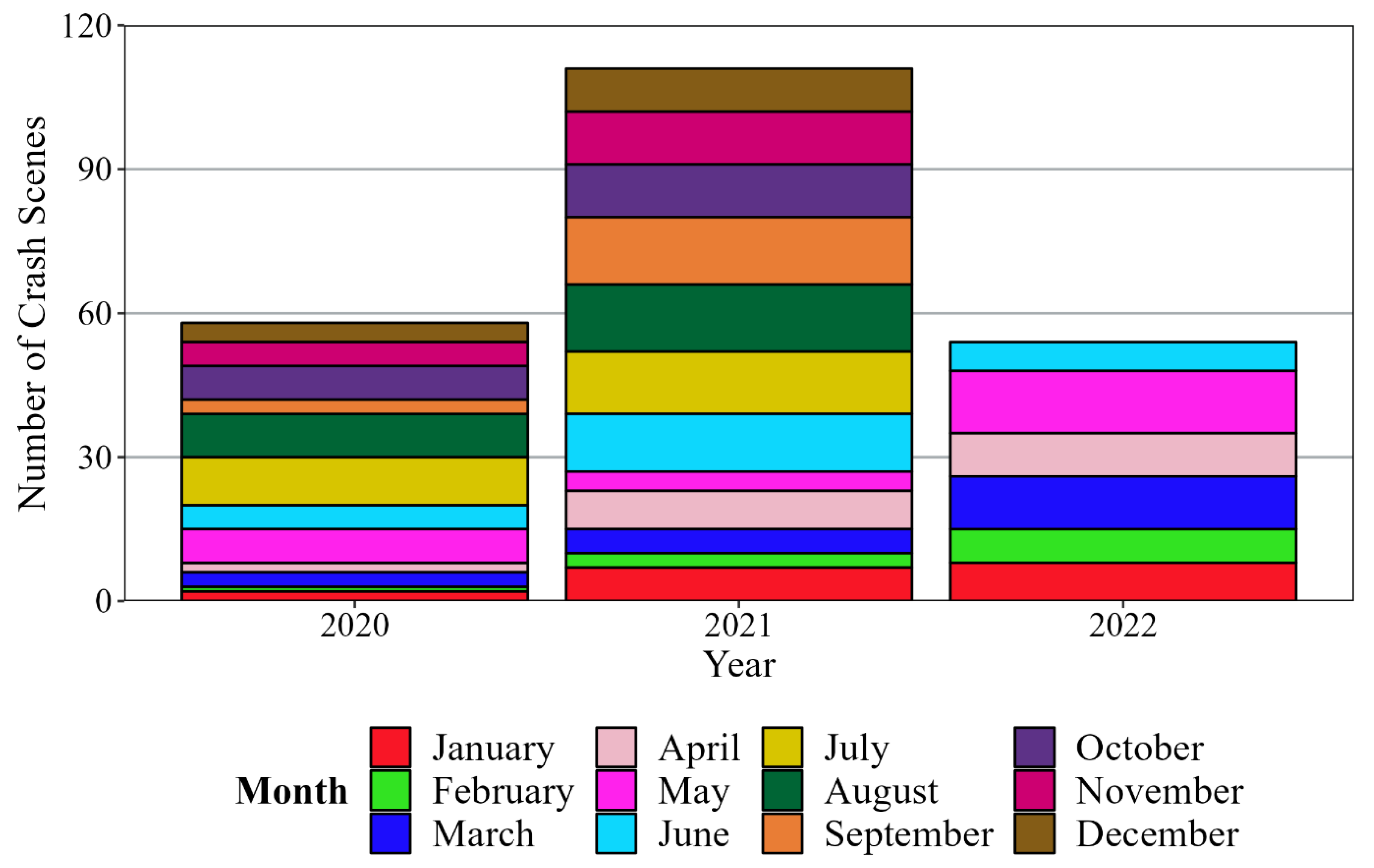
A summary chart of the number of crash scenes received over the years from participating public safety agencies around the state, utilized for the analyses in this study, is illustrated by Figure 2. The program has seen increasing participation with every passing year, with the number of crash scenes mapped by agencies using UAS increasing from 58 in 2020, to 111 in 2021 and 54 in 2022 (as of 4 July 2022).

3. Spatial Accuracy of UAS-Based Photogrammetric Crash Scene Mapping

This section documents the various scale measurements used by agencies on scene, the variance in number of scale measurements, as well as the camera models utilized for mapping the crash scenes analyzed by this study.

3.1. Scale Measurement Distances

Using processed results from the 223 crash scenes that included some form of scale measurement marked on scene, a summary representation of the scale measurement errors from these scenes is depicted by the histogram in Figure 3. The scale error is computed as the difference in distance between the actual ground measurement and the estimated output from the processing software. Estimating the errors from multiple scale distances reported by several scenes, the scale errors were found to be within 0.05 ft (1.5 cm). A cumulative frequency distribution plot of these errors in Figure 4. shows a median scale error of 0.0165 ft (0.5 cm) pointed to by callout (i) while callout (ii) points to 90% of scale errors being 0.13 ft (3.9 cm) or lower.
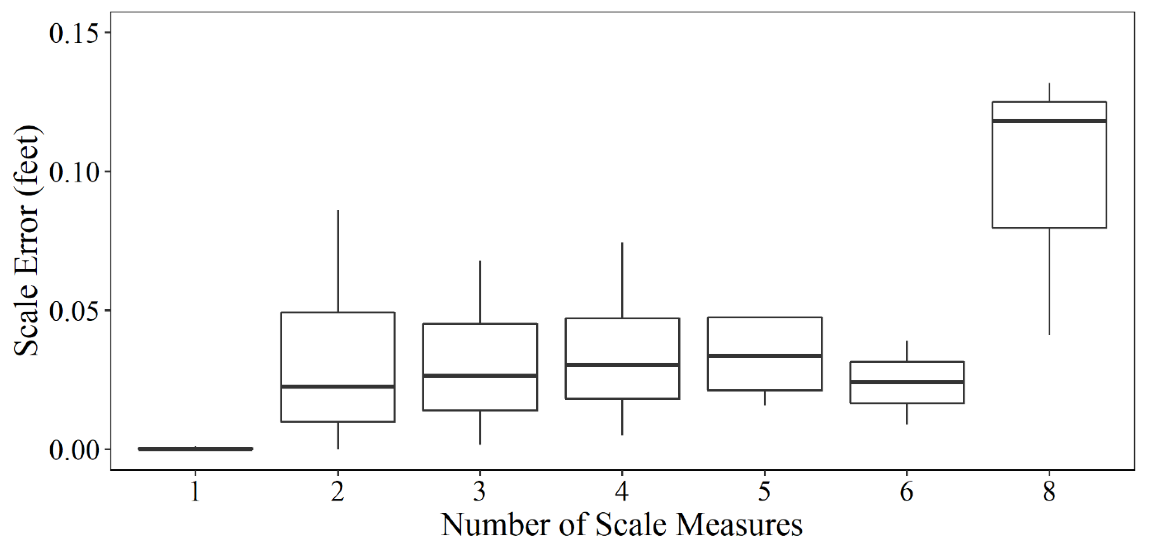
Figure 5 shows a boxplot comparing the variations in observed accuracy by number of scale measurements. Scenes with a single measurement will have an error of zero since more than one distance measurement is needed to check scale quality. Therefore, these instances should be discarded as the entire scene is being scaled using a single measurement. Across scenes with multiple scale measurements, those with 2–6 measurements were found to have a median accuracy ranging between 0.024 ft (0.7 cm) and 0.033 ft (1 cm), with two and six measurements having the highest median accuracy around 0.024 ft (0.7 cm). For scenes with eight measurements, the median error was found to be as high as 0.118 ft (3.6 cm). On further examination, it was found that only one scene reported eight measurements and hence this result need not be valid owing to sampling bias. However, this error is still well within acceptable thresholds for public safety and crash scene documentation applications.
The most frequent measurement choices for scale measurements among public safety agencies participating in the program were a 50 ft (1524 cm) and 100 ft (3048 cm) measure, as highlighted by the two leftmost columns in the pareto sorted chart of measurements (with a minimum frequency of 5) in Figure 6. 89 unique scale measurements and a total of 561 scale measurements were observed over the 223 crash scenes. The 50 ft (1524 cm) and 100 ft (3048 cm) measurements together account for nearly 53% of all recorded scale measurements.
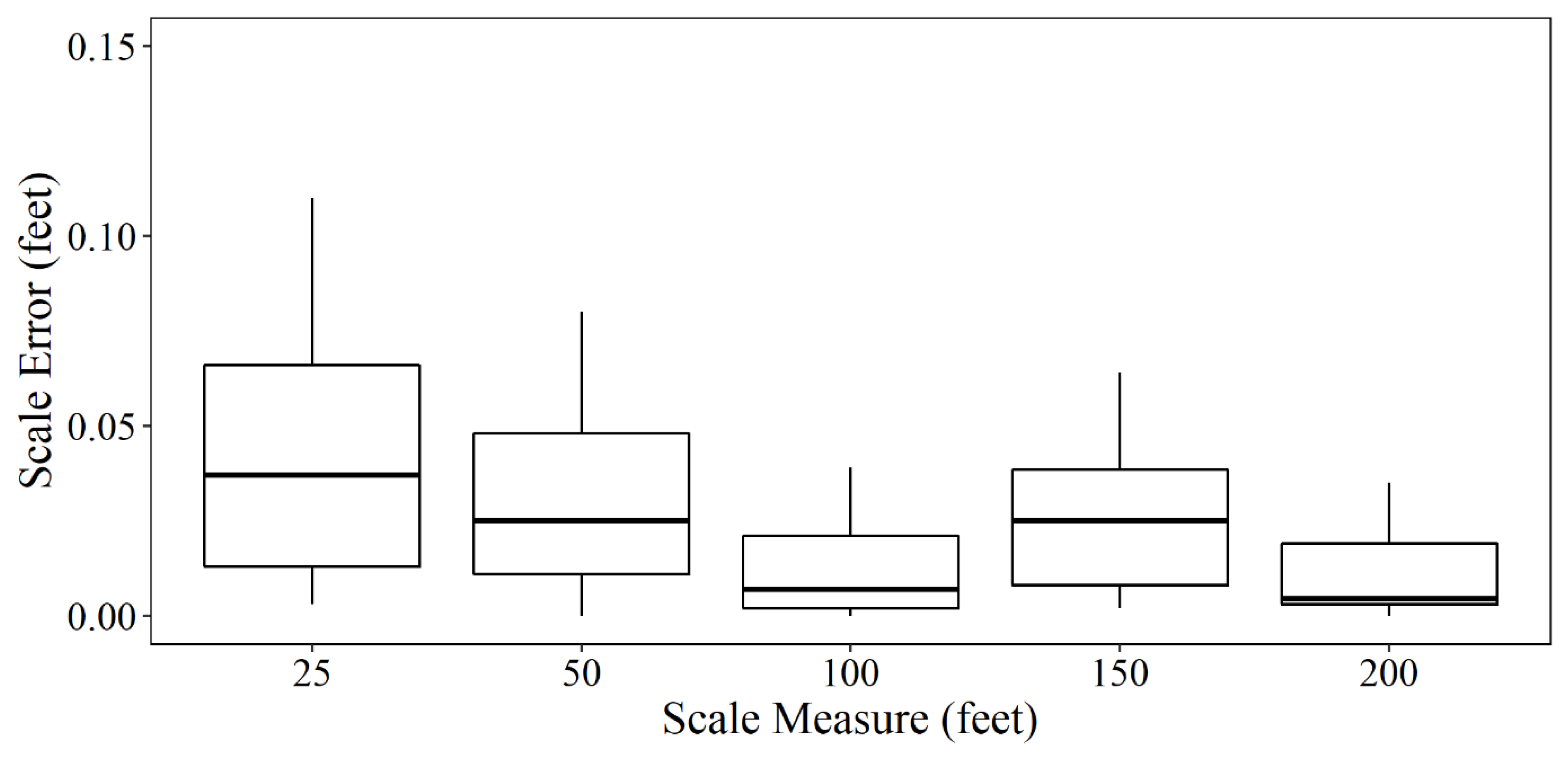
Figure 7 shows a box-and-whisker plot of the top five most frequently used scale measurements from Figure 6, namely 100 ft (3048 cm), 50 ft (1524 cm), 25 ft (762 cm), 150 ft (4572 cm) and 200 ft (6096 cm). The median scale error follows a generally decreasing trend as the length of the scale measure increases from 25 ft (762 cm) up to 200 ft (6096 cm) barring a few outliers for the 150 ft (4572 cm) scale measure causing a higher median error value. This points to conventional practices of longer scale measurements resulting in higher accuracy being confirmed by empirical evidence. As mentioned earlier, the scale error for each of these five measurements is still well within acceptable thresholds for public safety and crash scene documentation applications.

3.2. UAS Camera Models

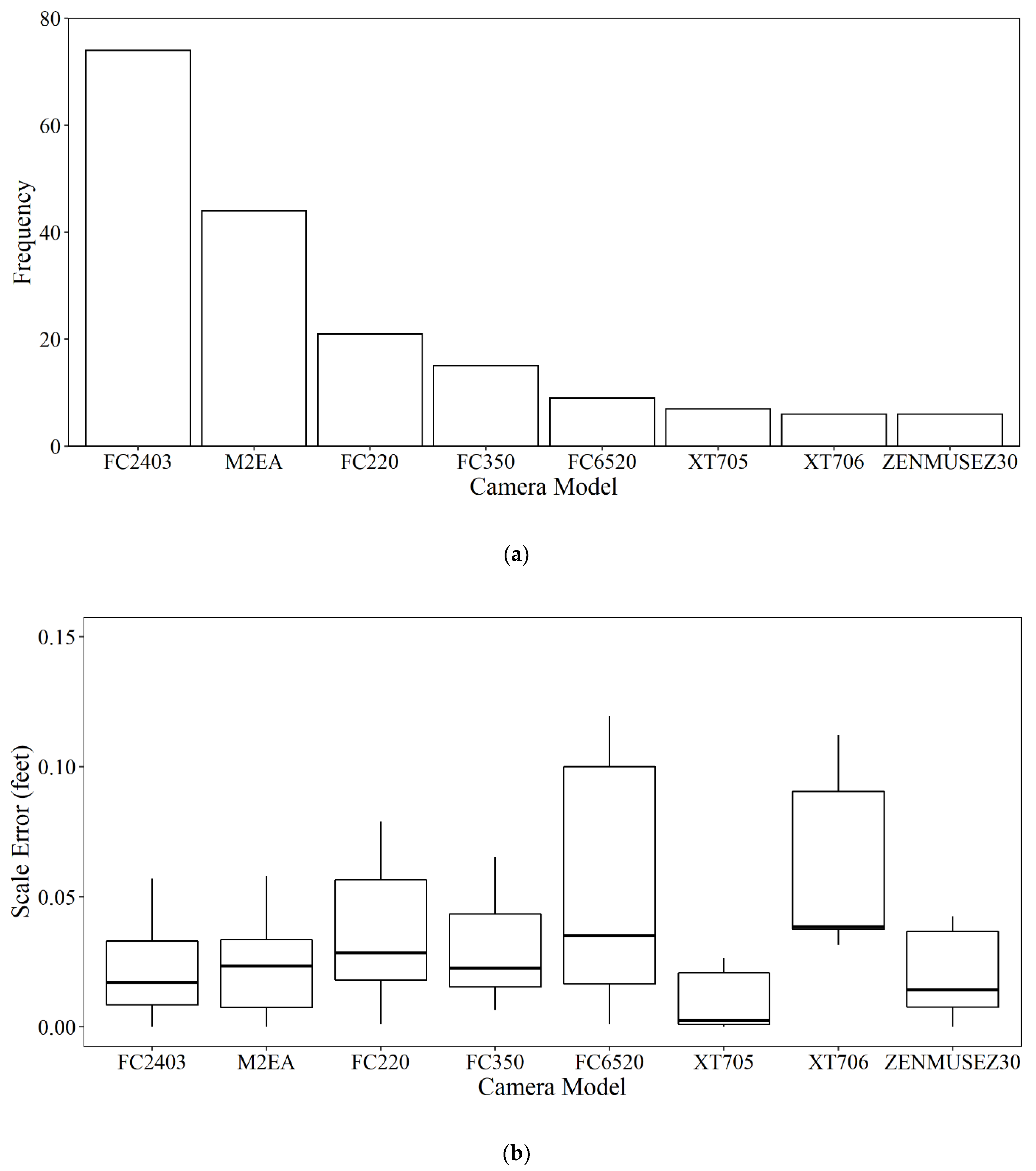
In addition to documenting the observed relationship between the number of scale measurements and scale measurement distances on the resulting errors, a corresponding analysis was carried out for visualizing the relationship between the UAS camera models and scale accuracy. Figure 8a shows the frequency of the camera models used in this study. The FC2403 is a camera model equipped on a number of UAS in the DJI Mavic series, one of the more affordable series of UAS with a small footprint making them quickly deployable in emergency situations. This camera was also observed to have been the most frequently used camera for mapping crash scenes. This camera was closely followed by the Mavic 2 Enterprise Advanced (M2EA) model. The third most frequently used camera model for mapping crash scenes was the FC220, generally supplied with the DJI Mavic Pro UAS. Figure 8b compares the accuracy of these camera models. XT705 (Autel EVO II), ZenmuseZ30 (M600), and FC2403 were found to have the least errors (median errors less than 0.017 ft or 0.5 cm).

4. Case Study Comparison with Terrestrial Measurements

A two-semi crash incident on 29 July 2020 near mile marker 178 on I-65 in Tippecanoe County resulted in a nearly 5-hour road closure in the northbound direction of travel and approximately 8-mile-long queues. In this particular case, the long closure was due to recovery and cleanup activities. During this closure, a UAS was used to quickly map the crash scene in order to get scene clearance and recovery efforts underway. A flight plan of the UAS mission flown to capture this crash scene is depicted in Figure 9. Callout (i) represents the start point from which the UAS started capturing images with every subsequent white dot representing an image capture location on the flight plan. Flight lines adopted by the UAS during this mission are indicated by black lines. These flight lines are fairly indicative of programmed flight lines for double grid missions flown by public safety agencies capturing crash scene imagery using UAS and provide for an acceptable level of overlap to ensure good quality of results. A total of 107 images were captured as part of this mapping, while flying over an area of 3.8 acres at an altitude of 120 ft (3657.6 cm). The mapping mission was able to be completed in 8 min with sufficient front and side overlap (each set to 80% for this incident) to ensure a good quality ortho-mosaic of the scene.
Following the image capture process, camera calibration is conducted as part of the implemented Structure from Motion (SfM) procedure. More specifically, the SfM procedure uses identified matches among overlapping images together with nominal, internal/external camera parameters (provided by the camera manufacturer and geo-tagged imagery) to estimate a refined set of internal/external camera parameters together with the object-space coordinates of matched points. There are several commercial [32,33] and open-source [34,35] realizations of SfM available to the UAS user community, in addition to custom transparent frameworks that account for the UAS trajectory and may include user-defined constraints [36,37].
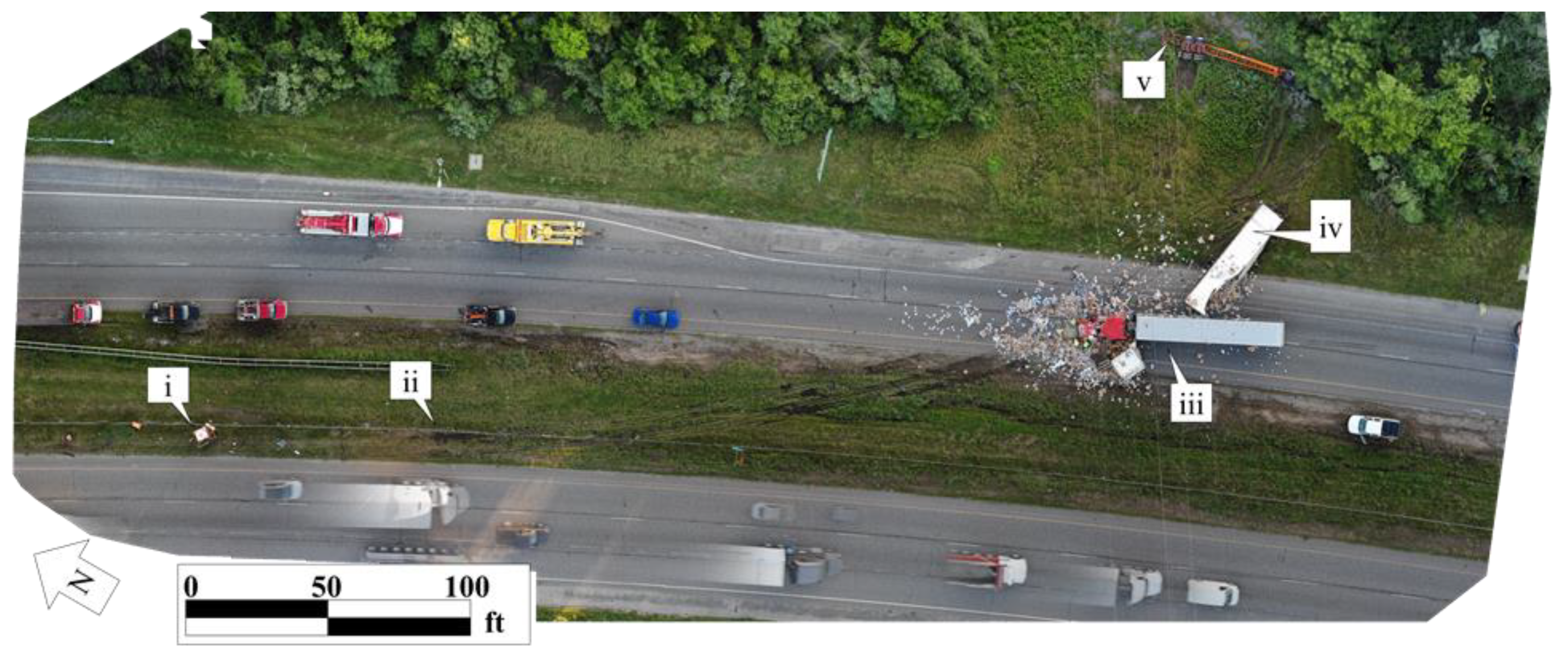
Figure 10 shows the UAS-based ortho-rectified mosaic of this crash scene, obtained as one of the results of the aforementioned procedures, with callouts identifying key aspects of the incident. Callout (i) points to a damaged sign on wheels first hit by the southbound semi. Callout (ii) shows the location where the semi cut across the cable barriers in the southbound lanes. Callout (iii) points to the location where the northbound semi impacts the trailer box of the first semi. Callout (iv) denotes the final position where the first semi’s trailer box came to rest, while callout (v) indicates the final resting position of the first semi. This graphic thus illustrates the significant amount of detail that could be captured by an 8-min flight as compared to the immense amount of time and effort that would have been required to capture terrestrial photographs of this scene that yield this level of detail.
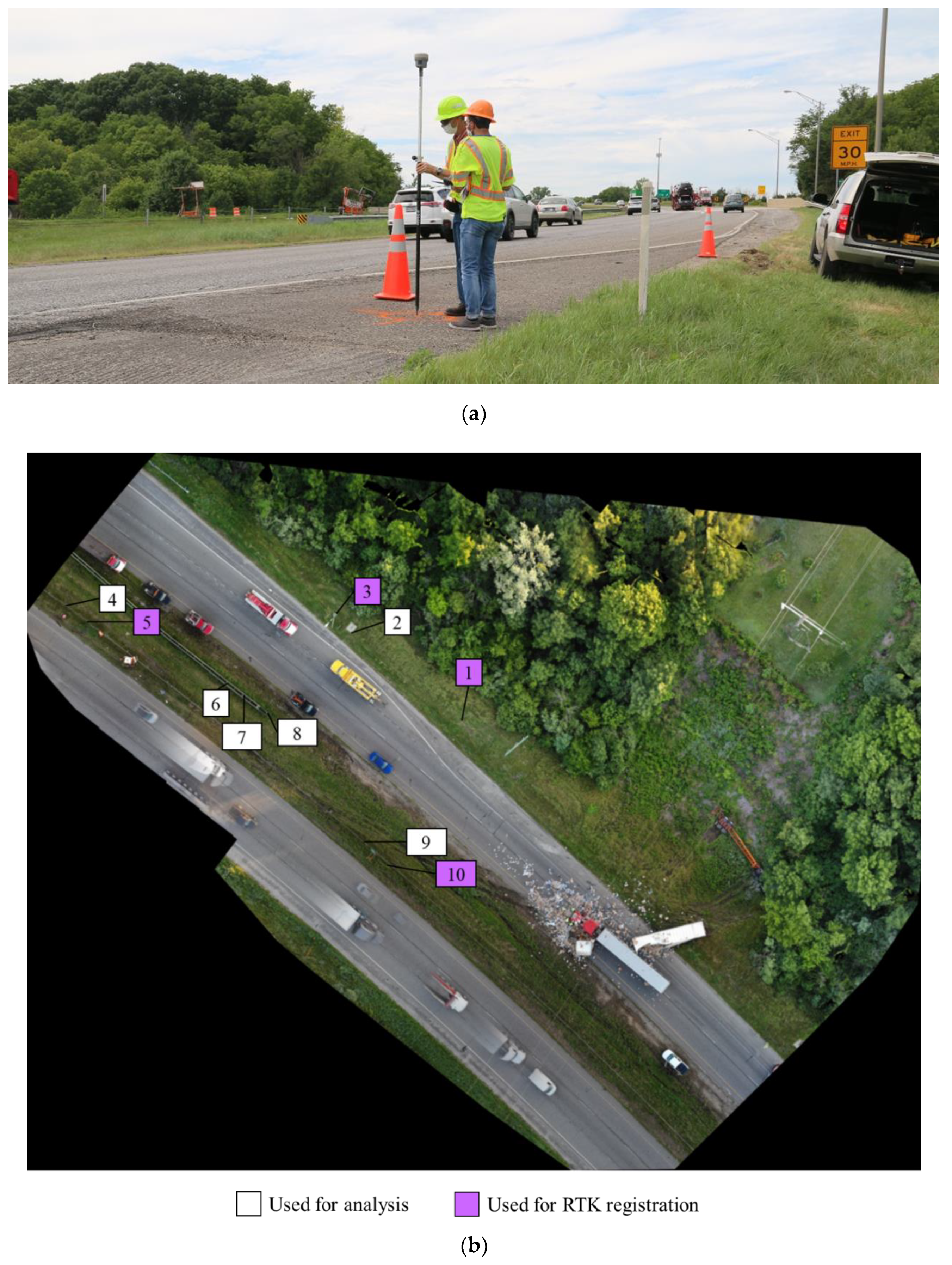
In order to evaluate the accuracy of the photogrammetric approach for reliable documentation of crash scenes, a total of ten points with a good distribution over the study site were identified and their ground coordinates were determined by means of a real-time kinematic (RTK) survey using a Trimble R10 GNSS receiver. Figure 11b shows the location of surveyed points along with a sample image shown in Figure 11a pertaining to the RTK measurement operation. As can be seen in Figure 11a, due to the challenging environment of the study site, the RTK survey was conducted without using a tripod and the operator had to manually hold the RTK pole during RTK measurements (for approximately 5 s per measurement).
For crash scene mapping purposes, absolute GPS position is not particularly important, but it is very important that the scaled ortho-mosaic images have good relative accuracy for preparing scale drawings and extracting important dimensions. Nominal geo-tagging information, provided by the onboard GPS unit on the UAS, is embedded in the image headers. This information is used in the SfM after assigning low confidence due to the consumer-grade nature of the GPS unit (i.e., the expected accuracy of such geo-tagging information is approximately 3 m). Due to this low accuracy, using a UAS-borne GPS unit for defining the scale is not reliable. Therefore, to ensure a more precise scale, the SfM results are augmented with control scaling distances through a second optimization process, for the scene in this case study as well as all scenes analyzed by this study. Quantitative analysis is conducted by evaluating the relative accuracy of the generated orthophoto from the UAS photogrammetric mapping mission and compared with survey grade RTK distances. Hence, points corresponding to the RTK measurements are manually measured on the generated orthophoto. It should be noted that the coordinate system defined by the photogrammetric approach and RTK survey might be different. Therefore, prior to conducting a comparative analysis, four well-distributed points (out of ten points), points 1, 3, 5 and 10 highlighted by purple callouts in Figure 11b, are first used to estimate the registration parameters–one scale, one rotation, and two shifts–between the two coordinate systems. Then, the coordinates of the remaining six points that were measured on the orthophoto are registered to the RTK-defined frame.
Finally, pairwise distances between the remaining six points–i.e., a total of 15 distances–are estimated. Table 1 reports the orthophoto-derived and RTK-derived distances for each of these 15 pairwise distances labeled as segments A through O along with their respective endpoints. As shown by the error column in this table, there is a good agreement between the two sources of measurements. More specifically, the root-mean-square error (RMSE) value of the differences between distances estimated from the orthophoto and RTK is in the range of 0.13 ft (3.9 cm). According to the fact that a change of 1 ° of the RTK pole during data collection can result in an error of 0.11 ft (3.3 cm), the relative accuracy of the generated orthophoto can be considered as well within the range of RTK measurement error.

5. Discussion and Conclusions

This paper presents an assessment of Indiana’s ongoing UAS-based crash scene mapping program witnessing participation from 35 public safety agencies around the state. A highly scalable and centralized processing framework adopted by the program enabled public safety agencies to focus their efforts on image acquisition and reducing incident clearance times.
This study analyzed data from close to 250 crash scenes to understand the accuracy of measurements from the orthophoto generated using UAS images. Results showed that 90% of the scale errors were found to be within 0.13 ft (3.9 cm) with a median scale error of 0.02 ft (0.5 cm). The most frequent measurement choices for scale measurements were a 50 ft (1524 cm) and 100 ft (3048 cm) measure. In general, the median scale error followed a generally decreasing trend as the length of the scale measure increased from 25 ft (762 cm) up to 200 ft (6096 cm), except for 150 ft (4572 cm). The study also analyzed the different camera models used for capturing the crash scenes. While FC2403 was observed to have been the most frequently used camera for mapping crash scenes, XT705 (Autel EVO II), ZenmuseZ30 (M600) and FC2403 were found to have the least measurement errors with median errors less than 0.017 ft or 0.5 cm. Finally, a case study showing measurement comparisons between terrestrial RTK, and UAS-based mapping, showed good agreement with RMSE in the range of 0.13 ft (3.96 cm), a fairly acceptable threshold for crash scene documentation applications.
As UAS-based crash scene mapping and documentation is gaining popularity among public safety agencies and first responders, it is critical to validate the measurements and results obtained using this procedure. The analysis and results presented in this study characterize the accuracy of this method in estimating ground distances while flying the missions and collecting data in a short period of time. Even though more expensive equipment can deliver measurements that are more precise, UAS-based mapping is a viable option for public safety agencies because of its accuracy, affordability, and efficiency.

Author Contributions

Conceptualization, J.D., J.K.M., R.H., D.H., A.H. and D.M.B.; data curation, J.D., J.K.M., Y.Z., R.H., S.M.H., A.H. and D.M.B.; formal analysis, J.D., J.K.M., Y.Z., S.M.H., A.H. and D.M.B.; funding acquisition, R.H., D.H., A.H. and D.M.B.; investigation, J.D., J.K.M., Y.Z., R.H., S.M.H., A.H. and D.M.B.; methodology, J.D., J.K.M., Y.Z., S.M.H., A.H. and D.M.B.; project administration, J.K.M., R.H., D.H., A.H. and D.M.B.; resources, D.H.; supervision, J.D., J.K.M., R.H., D.H., A.H. and D.M.B.; validation, J.D., J.K.M., R.H. and S.M.H.; visualization, J.D., J.K.M., Y.Z. and S.M.H.; writing—original draft, J.D., J.K.M., Y.Z., D.H., S.M.H., A.H. and D.M.B.; writing—review & editing, J.D., J.K.M., Y.Z., R.H., D.H., S.M.H., A.H. and D.M.B. All authors have read and agreed to the published version of the manuscript.

Funding

This work was supported by the Indiana Criminal Justice Institute (Contract #48906).

Institutional Review Board Statement

Not Applicable.

Informed Consent Statement

Not Applicable.

Acknowledgments

This work was supported by the Indiana Criminal Justice Institute and the Joint Transportation Research Program administered by the Indiana Department of Transportation and Purdue University. The contents of this paper reflect the views of the authors, who are responsible for the facts and the accuracy of the data presented herein, and do not necessarily reflect the official views or policies of the sponsoring organizations. These contents do not constitute a standard, specification, or regulation.

Conflicts of Interest

The authors declare no conflict of interest.

References

  1. Nikolakopoulos, K.G.; Lampropoulou, P.; Fakiris, E.; Sardelianos, D.; Papatheodorou, G. Synergistic Use of UAV and USV Data and Petrographic Analyses for the Investigation of Beachrock Formations: A Case Study from Syros Island, Aegean Sea, Greece. Minerals 2018, 8, 534. [Google Scholar] [CrossRef]
  2. Wang, D.; Xing, S.; He, Y.; Yu, J.; Xu, Q.; Li, P. Evaluation of a New Lightweight UAV-Borne Topo-Bathymetric LiDAR for Shallow Water Bathymetry and Object Detection. Sensors 2022, 22, 1379. [Google Scholar] [CrossRef] [PubMed]
  3. Abd-Elrahman, A.; Quirk, B.; Corbera, J.; Habib, A. Small Unmanned Aerial System Development and Applications in Precision Agriculture and Natural Resource Management. Eur. J. Remote Sens. 2019, 52, 504–505. [Google Scholar] [CrossRef]
  4. Bolourian, N.; Hammad, A. LiDAR-Equipped UAV Path Planning Considering Potential Locations of Defects for Bridge Inspection. Autom. Constr. 2020, 117, 103250. [Google Scholar] [CrossRef]
  5. Barmpounakis, E.N.; Vlahogianni, E.I.; Golias, J.C. Unmanned Aerial Aircraft Systems for Transportation Engineering: Current Practice and Future Challenges. Int. J. Transp. Sci. Technol. 2016, 5, 111–122. [Google Scholar] [CrossRef]
  6. Outay, F.; Mengash, H.A.; Adnan, M. Applications of Unmanned Aerial Vehicle (UAV) in Road Safety, Traffic and Highway Infrastructure Management: Recent Advances and Challenges. Transp. Res. Part A: Policy Pract. 2020, 141, 116–129. [Google Scholar] [CrossRef] [PubMed]
  7. Coifman, B.; McCord, M.; Mishalani, R.G.; Redmill, K. Surface Transportation Surveillance from Unmanned Aerial Vehicles. In Proceedings of the 83rd Annual Meeting of the Transportation Research Board, Washington, DC, USA, 11–15 January 2004; pp. 209–219. [Google Scholar]
  8. Farradine, P.B. Use of Unmanned Aerial Vehicles in Traffic Surveillance and Traffic Management; Technical Memorandum Prepared For Florida Department of Transportation: Tallahassee, FL, USA, 2005. [Google Scholar]
  9. McCormack, E. The Use of Small Unmanned Aircraft by the Washington State Department of Transportation; Department of Transportation: Washington, DC, USA, 2008. [Google Scholar]
  10. Gheisari, M.; Esmaeili, B. Applications and Requirements of Unmanned Aerial Systems (UASs) for Construction Safety. Saf. Sci. 2019, 118, 230–240. [Google Scholar] [CrossRef]
  11. Gheisari, M.; Karan, E.P.; Christmann, H.C.; Irizarry, J.; Johnson, E.N. Investigating Unmanned Aerial System (UAS) Application Requirements within a Department of Transportation. In Proceedings of the Transportation Research Board 94th Annual Meeting, Transportation Research Board, Washington, DC, USA, 11–15 January 2015. [Google Scholar]
  12. Zink, J.; Lovelace, B. Unmanned Aerial Vehicle Bridge Inspection Demonstration Project. 2015. Available online: http://www.dot.state.mn.us/research/TS/2015/201540TS.pdf (accessed on 5 September 2022).
  13. Seo, J.; Duque, L.; Wacker, J.P. Field Application of UAS-Based Bridge Inspection. Transp. Res. Rec. 2018, 2672, 72–81. [Google Scholar] [CrossRef]
  14. Owens, N.D.; Armstrong, A.H.; Mitchell, C.; Brewster, R. Federal Highway Administration Focus States Initiative: Traffic Incident Management Performance Measures Final Report; Federal Highway Administration: Washington, DC, USA, 2009. [Google Scholar]
  15. Desai, J.; Sakhare, R.; Rogers, S.; Mathew, J.K.; Habib, A.; Bullock, D. Using Connected Vehicle Data to Evaluate Impact of Secondary Crashes on Indiana Interstates. In Proceedings of the 2021 IEEE International Intelligent Transportation Systems Conference (ITSC), Indianapolis, IN, USA, 19–21 September 2021. [Google Scholar]
  16. Liu, X.; Zou, H.; Niu, W.; Song, Y.; He, W. An Approach of Traffic Accident Scene Reconstruction Using Unmanned Aerial Vehicle Photogrammetry. In Proceedings of the 2019 2nd International Conference on Sensors, Signal and Image Processing, 8–Prague, Czech Republic, 8–10 October 2019. [Google Scholar]
  17. Liu, Y.; Bai, B.; Zhang, C. UAV Image Mosaic for Road Traffic Accident Scene. In Proceedings of the 2017 32nd Youth Academic Annual Conference of Chinese Association of Automation (YAC), Hefei, China, 19–21 May 2017. [Google Scholar]
  18. Bullock, J.L.; Hainje, R.; Habib, A.; Horton, D.; Bullock, D.M. Public Safety Implementation of Unmanned Aerial Systems for Photogrammetric Mapping of Crash Scenes. Transp. Res. Rec. 2019, 2673, 567–574. [Google Scholar] [CrossRef]
  19. Jacobson, L.N.; Legg, B.; O’Brien, A.J. Incident Management Using Total Stations; Transportation Research Record: Thousand Oaks, CA, USA, 1992. [Google Scholar]
  20. Agent, K.R.; Deacon, J.A.; Pigman, J.G.; Stamatiadis, N. Evaluation of Advanced Surveying Technology for Accident Investigation (1994). Kentucky Transportation Center Research Report. 433. Available online: https://uknowledge.uky.edu/ktc_researchreports/433/ (accessed on 5 September 2022).
  21. Forman, P.; Parry, I. Rapid data collection at major incident scenes using three dimensional laser scanning techniques. In Proceedings of the IEEE 35th Annual 2001 International Carnahan Conference on Security Technology (Cat. No. 01CH37186), London, UK, 16–19 October 2001; IEEE: Piscataway, NJ, USA, 2001. [Google Scholar]
  22. Poole, G.; Venter, P.R. Measuring Accident Scenes Using Laser Scanning Systems and the Use of Scan Data in 3D Simulation and Animation. In Proceedings of the 23rd Annual Southern African Transport Conference 2004, Pretoria, South Africa, 12–15 July 2004. [Google Scholar]
  23. Desai, J.; Liu, J.; Hainje, R.; Oleksy, R.; Habib, A.; Bullock, D. Assessing Vehicle Profiling Accuracy of Handheld LiDAR Compared to Terrestrial Laser Scanning for Crash Scene Reconstruction. Sensors 2021, 21, 8076. [Google Scholar] [CrossRef] [PubMed]
  24. Pagounis, V.; Tsakiri, M.; Palaskas, S.; Biza, B.; Zaloumi, E. 3D Laser Scanning for Road Safety and Accident Reconstruction. In Proceedings of the XXIIIth International FIG Congress, Munich, Germany, 8–13 October 2006; p. 13. [Google Scholar]
  25. Osman, M.R.; Tahar, K.N. 3D Accident Reconstruction Using Low-Cost Imaging Technique. Adv. Eng. Softw. 2016, 100, 231–237. [Google Scholar] [CrossRef]
  26. Du, X.; Jin, X.; Zhang, X.; Shen, J.; Hou, X. Geometry Features Measurement of Traffic Accident for Reconstruction Based on Close-Range Photogrammetry. Adv. Eng. Softw. 2009, 40, 497–505. [Google Scholar] [CrossRef]
  27. Žuraulis, V.; Levulytė, L.; Sokolovskij, E. Vehicle Speed Prediction from Yaw Marks Using Photogrammetry of Image of Traffic Accident Scene. Procedia Eng. 2016, 134, 89–94. [Google Scholar] [CrossRef]
  28. Jiao, P.; Miao, Q.; Zhang, M.; Zhao, W. A Virtual Reality Method for Digitally Reconstructing Traffic Accidents from Videos or Still Images. Forensic Sci. Int. 2018, 292, 176–180. [Google Scholar] [CrossRef] [PubMed]
  29. Chu, T.; Starek, M.J.; Berryhill, J.; Quiroga, C.; Pashaei, M. Simulation and Characterization of Wind Impacts on SUAS Flight Performance for Crash Scene Reconstruction. Drones 2021, 5, 67. [Google Scholar] [CrossRef]
  30. Kamnik, R.; Nekrep Perc, M.; Topolšek, D. Using the Scanners and Drone for Comparison of Point Cloud Accuracy at Traffic Accident Analysis. Accid. Anal. Prev. 2020, 135, 105391. [Google Scholar] [CrossRef] [PubMed]
  31. Pérez, J.A.; Gonçalves, G.R.; Rangel, J.M.G.; Ortega, P.F. Accuracy and Effectiveness of Orthophotos Obtained from Low Cost UASs Video Imagery for Traffic Accident Scenes Documentation. Adv. Eng. Softw. 2019, 132, 47–54. [Google Scholar] [CrossRef]
  32. Professional Photogrammetry and Drone Mapping Software. Pix4D. Available online: https://www.pix4d.com/ (accessed on 5 September 2022).
  33. Agisoft Metashape: Agisoft Metashape. Available online: https://www.agisoft.com/ (accessed on 5 September 2022).
  34. VisualSFM: A Visual Structure from Motion System. Available online: http://ccwu.me/vsfm/index.html (accessed on 5 September 2022).
  35. Drone Mapping Software. OpenDroneMap. Available online: https://www.opendronemap.org/ (accessed on 5 September 2022).
  36. Hasheminasab, S.M.; Zhou, T.; Habib, A. GNSS/INS-Assisted Structure from Motion Strategies for UAV-Based Imagery over Mechanized Agricultural Fields. Remote Sens. 2020, 12, 351. [Google Scholar] [CrossRef]
  37. He, F.; Zhou, T.; Xiong, W.; Hasheminnasab, S.M.; Habib, A. Automated Aerial Triangulation for UAV-Based Mapping. Remote Sens. 2018, 10, 1952. [Google Scholar] [CrossRef] [Green Version]
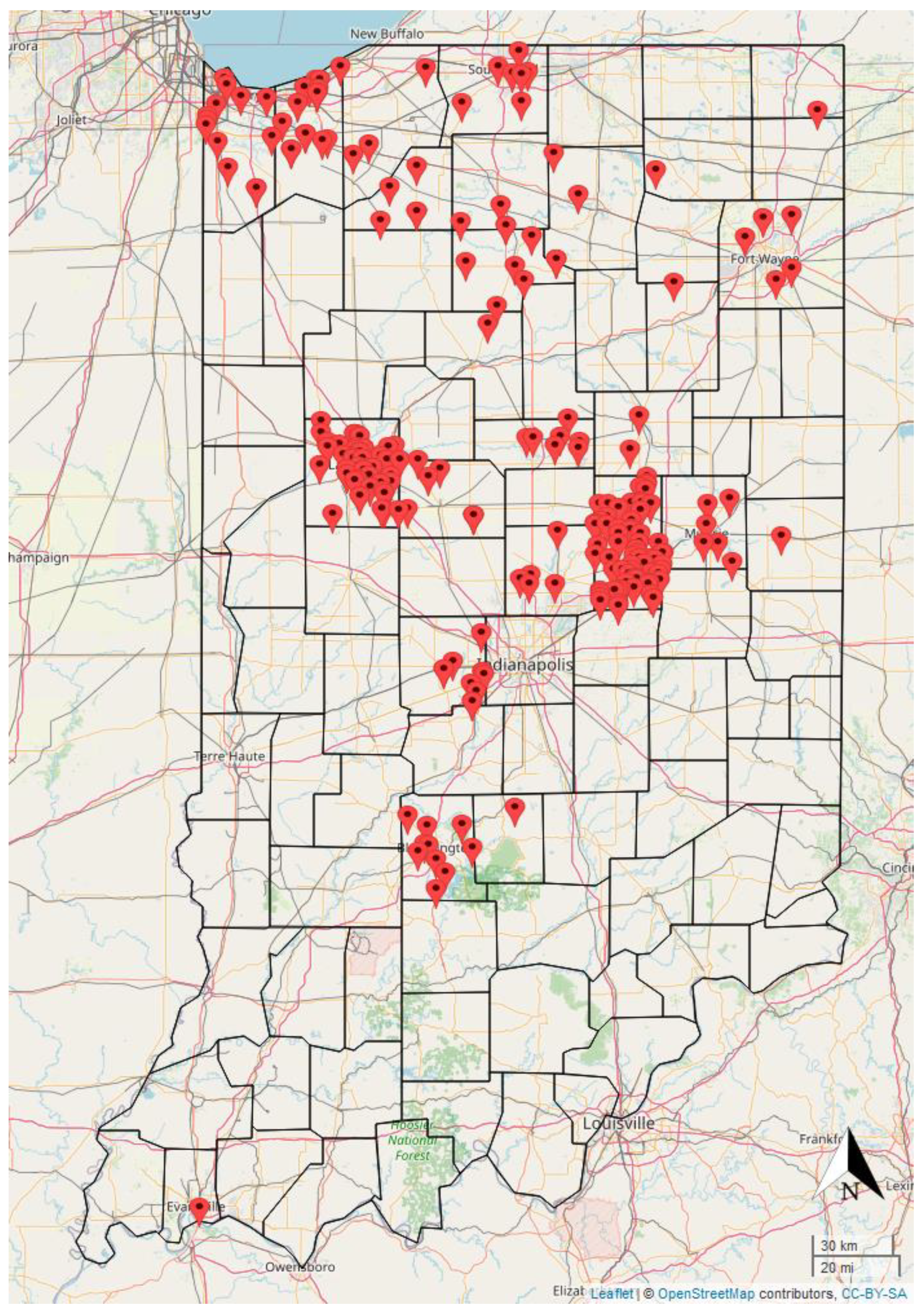
Figure 1. Overview map of 252 crash scene locations.
Drones 06 00259 g001
Figure 2. Number of scenes received by year (numbers for 2022 are current as of 4 July 2022).
Drones 06 00259 g002
Figure 3. Histogram of scale error.
Drones 06 00259 g003
Figure 4. Cumulative frequency distribution of scale errors.
Drones 06 00259 g004
Figure 5. Impact of number of scale measurements on accuracy.
Drones 06 00259 g005
Figure 6. Pareto sorted frequency chart of scale measurements.
Drones 06 00259 g006
Figure 7. Scale Errors versus Length of Scale Measurements (Filtered by Top Five Most Frequently Used Scale Measurements).
Drones 06 00259 g007
Figure 8. Top Eight Most Frequently Used Camera Models and Associated Scale Errors: (a) most frequently used camera models for UAS-based mapping; and (b) scale errors for most frequently used camera models.
Drones 06 00259 g008
Figure 9. UAV Mission Flight plan depicting Image Capture Locations.
Drones 06 00259 g009
Figure 10. Scaled UAS ortho-rectified mosaic of scene with crash scene labels.
Drones 06 00259 g010
Figure 11. RTK Base Station Data Collection Procedure and Locations: (a) RTK data collection procedure; and (b) RTK data collection locations.
Drones 06 00259 g011
Table 1. Comparison of relative distances after scaling and RTK registration.
Measured SegmentSegment Endpoints
(from Figure 11)
Orthophoto (ft)RTK (ft)Error (ft)
AP2, P4160.79160.750.03
BP2, P682.3082.38−0.08
CP2, P777.3477.47−0.13
DP2, P873.1773.31−0.14
EP2, P9132.21132.38−0.16
FP4, P694.0594.11−0.06
GP4, P7106.18106.140.04
HP4, P8124.99124.840.15
IP4, P9218.88218.800.07
JP6, P712.4512.340.11
KP6, P831.6231.380.23
LP6, P9129.85129.700.16
MP7, P819.1619.040.12
NP7, P9117.64117.600.04
OP8, P998.9999.08−0.09
Publisher’s Note: MDPI stays neutral with regard to jurisdictional claims in published maps and institutional affiliations.