Article

Design of a UAV for Autonomous RFID-Based Dynamic Inventories Using Stigmergy for Mapless Indoor Environments

Ubiquitous Computing Applications Laboratory, Department of Information and Communication Technologies, Universitat Pompeu Fabra, 08002 Barcelona, Spain
*
Author to whom correspondence should be addressed.
Drones 2022, 6(8), 208; https://doi.org/10.3390/drones6080208
Submission received: 12 July 2022 / Revised: 7 August 2022 / Accepted: 12 August 2022 / Published: 16 August 2022
(This article belongs to the Section Drone Design and Development)

Abstract

:
Unmanned aerial vehicles (UAVs) and radio frequency identification (RFID) technology are becoming very popular in the era of Industry 4.0, especially for retail, logistics, and warehouse management. However, the autonomous navigation for UAVs in indoor map-less environments while performing an inventory mission is, to this day, an open issue for researchers. This article examines the method of leveraging RFID technology with UAVs for the problem of the design of a fully autonomous UAV used for inventory in indoor spaces. This work also proposes a solution for increasing the performance of the autonomous exploration of inventory zones using a UAV in unexplored warehouse spaces. The main idea is to design an indoor UAV equipped with an onboard autonomous navigation system called RFID-based stigmergic and obstacle avoidance navigation system (RFID-SOAN). RFID-SOAN is composed of a computationally low cost obstacle avoidance (OA) algorithm and a stigmergy-based path planning and navigation algorithm. It uses the same RFID tags that retailers add to their products in a warehouse for navigation purposes by using them as digital pheromones or environmental clues. Using RFID-SOAN, the UAV computes its new path and direction of movement based on an RFID density-oriented attraction function, which estimates the optimal path through sensing the density of previously unread RFID tags in various directions relative to the pose of the UAV. We present the results of the tests of the proposed RFID-SOAN system in various scenarios. In these scenarios, we replicate different typical warehouse layouts with different tag densities, and we illustrate the performance of the RFID-SOAN by comparing it with a dead reckoning navigation technique while taking inventory. We prove by the experiments results that the proposed UAV manages to adequately estimate the amount of time it needs to read up-to 99.33% of the RFID tags on its path while exploring and navigating toward new zones of high populations of tags. We also illustrate how the UAV manages to cover only the areas where RFID tags exist, not the whole map, making it very efficient, compared to the traditional map/way-points-based navigation.

1. Introduction

Industry 4.0 has paved the way for a world where smart factories will automate and upgrade many processes through the use of some of the latest emerging technologies [1]. Two of these important technologies are UAVs and RFID. UAVs have evolved a great deal in the last several years in terms of technology (e.g., autopilots, sensors, power efficient motors, battery capacities and sizes) [2,3], and have reduced significantly in their cost. UAVs can help the automobile industry and in performing tedious tasks [4,5]. One of the important tasks is performing inventory missions in warehouses. Another is exploring new inventory zones in dynamic stock warehouses, which is an important factor for dynamic inventory management (DIM). DIM allows to detect the risk of stock-outs and overstocks and respond to it by adjusting targets and sales projections [6]. DIM helps reduce unnecessary shortages, improve sales, margins and inventory turns. Manual inventory needs the mobility of a lot of resources, especially in big warehouses belonging to big supply chains, where shelves can easily reach heights of 10 m. This causes delays in inventory management due to the time consumption of the task. Workers are also prone to injuries when performing inventory management where products represented as RFID tags are located at great heights. Furthermore, high costs are associated with manual inventory due to the costs of the inventory workers and blocking warehouse activities during the process. Many efforts have been made for automating the inventory process. We will focus in this paper on a solution that exploits the mobility and the ability of a UAV to carry RFID sensors. This enables the UAV to be a great candidate to replace humans for the tasks of dynamic inventory in warehouses. Moreover, they represent a great economic solution for the task, as well as the diminution of the time consumption and injury risks of the task. This paper also aims to mitigate the human intervention that associates most conventional map-based inventory robots which is needed to help create a reference map of the warehouse environment, this is achieved by increasing the autonomy and ability of the UAV to navigate in map-less indoor environments, exploring new inventory zones, and performing an inventory mission. The study in this paper addresses the design of a UAV that uses a navigation strategy based on strigmergy.
The basic idea of stigmergy is that traces left within an environment trigger an action that stimulates the performance of a future action [7,8]. Robots can benefit from using the concept of stigmergy. The conventional computational paradigm of robotics typically involves sensing the surrounding environment, analyzing features, building or modifying the world model/map, processing this information to find some sequence of actions which might lead to the success of a given mission, then executing that action sequence one step at a time while updating the world model/map and re-planning, if necessary, at any stage. The fit between stigmergy and behavior-based [9] robots is excellent. It is the essence of stigmergy that the consequences of behavior affect subsequent behavior. Behavior-based robots cope well with unstructured dynamic environments and are inexpensive [10]. UAVs, if designed as behavior-based robots, can benefit tremendously from stigmergy. In this paper, we introduce a UAV design that uses an RFID-oriented stigmergy algorithm for navigation, which provides a solution for full autonomy toward completing an inventory mission, doing so in unknown and unexplored areas. The ability of the UAV to decide and plan its consecutive path simply by following evidence and signs from the environment enables the UAV to be more autonomous throughout the whole inventory mission. The proposed RFID-SOAN only uses the existing RFID tags in a warehouse as input for navigating and path planning. This paper is structured as follows. Section 2 presents the state of the art. Section 3 is dedicated to the hardware design architecture. Section 4 presents the RFID-SOAN algorithm. The results of the experiments and simulations are described in Section 5 and Section 6. Section 7 summarizes the conclusions of this work, and Section 8 presents the future work.

2. Related Work

In the past, there has been a variety of research studying the exploitation of UGVs with RFID technology for performing stock counting missions and taking a full inventory of retail shops [11,12]. However, the fact that these inventory robots are ground surface robots, means that they would perform poorly in big warehouses where products are placed on very high shelves. For this reason, the method of combining both technologies, RFID and UAVs, is gaining interest in logistics, retail and other sectors. Research in [13,14], show different applications on UAVs carrying RFID systems. Recently, research has shown a rising interest in inventory task-oriented UAVs. This is due to the possibility of exploiting the 3D plane and the UAVs 6-degrees of freedom. However, this technology is still at its early stage, although some companies advertise solutions for the problem of an aerial inventory [15,16,17]. A related study in [18], discusses the application of UAVs for the purpose of product scanning in inventory and stock management using RFID in warehouses. Researchers from Samsung electronics [19] have tried to solve the problems of robust navigation, stability, and robust aerial inventory for warehouses. In [20], researchers from GyeongSang National University used UAVs on an inventory checking system based on RFID technology in open storage yard. These platforms either still lack the autonomy of the UAV in an indoor environment, or lack the ability to operate in unknown or dynamic environments, where the UAV navigates without a reference map of the environment.
Some research has been applied toward using stigmergy for increasing the autonomy of a robot; this is explored in [21,22,23]. In Ref. [24], the authors propose a solution for efficient supply chain management (SCM) by maintaining an accurate and close to real time inventory of items using an unmanned ground vehicle (UGV). Their proposed algorithm uses the same RFID tags that retailers add to their products, so they can guide the robot to navigate through a complete stock counting task in the case of a dynamic inventory mission. This increases the autonomy of the UGV using stigmergy. This study is used as a starting point for our proposed navigation technique. Although inventory UGVs perform well in retail shops with uniformed ground surfaces or operating in small sized warehouses, these robots have constraints when it comes to operating in big warehouses where shelves are too high to be read from the ground or in non-uniformed ground surface warehouses. This is where we exploit the superiority of UAVs in such cases. The proposed solution in this paper addresses big warehouses and environments with tall shelves, where continuous inventory in dynamic environments is needed and no prior map is given to the UAV for navigation. Integrating the algorithm and the navigation system that is used in [24] is too computationally expensive for UAVs, due to the limited computational capacity of these small machines. However, the design we propose can be considered an extension of the RFID stigmergic navigation paradigm, but more specialized for small-scale UAVs or behavioral-based robots.

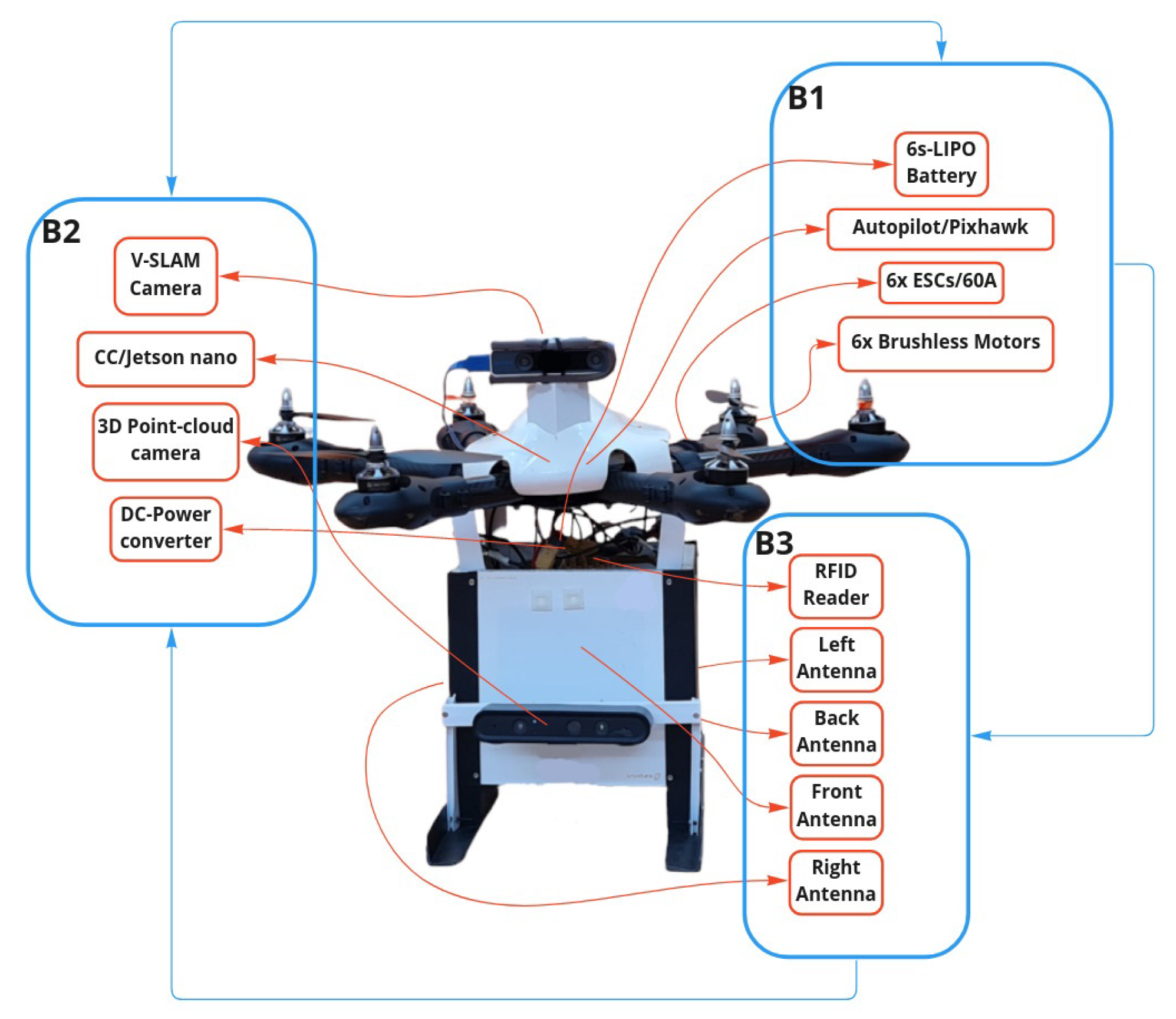
3. Hardware Design and Functionality

The UAV is expected to operate in indoors (GNSS-denied) environments, where no prior information of the environment nor a map are provided to the UAV. Therefore, the design of a UAV that can self-localize indoors without the help of a reference map nor external sensors was a primary goal. The UAV is also expected to carry a relatively big and heavy payload while being able to fly for a task sufficient flight time duration. No such model that meets the intended requirements was accessible in the market. Therefore, the design of a relatively cost-effective custom UAV for such a task was needed. The UAV design, shown in Figure 1, is composed of three hardware blocks: B1, B2, and B3.

3.1. Main Flight System, B1

The first block is the main flight system, which consists of the hardware needed to enable the UAV to fly and carry a heavy payload, while maintaining a stable flight for an amount of time that is necessary to complete the inventory task. Therefore, a hexacopter frame layout with an efficient open-source autopilot (Pixhawk 2.4.8) that is compatible to operate with a companion computer was chosen for this model. B1 block is responsible for enabling the UAV to take off and hover with some degree of stability, which means that most of the flight dynamics are managed by the hardware in this block. The hardware includes an efficient high speed and high torque brush-less motors (T-motors 750 kv), large pitch propellers (15 × 4.5 ), and electronic speed controllers (ESCs) with 45 amps of output current capacity. The ESCs translate the received signal messages from the autopilot to sufficient energy that is supplied to each motor.

3.2. Sensors and Processing Units, B2

This block is responsible for adding intelligence to the contiguous flight system block. Most inventory warehouses or retail shops are indoor spaces or GPS-denied spaces. This led us to install a visual simultaneous localization and mapping (VSLAM) based camera (Realsense intel t265) to supply the autopilot with self localization messages and act as a source of the odometry. Special adaptation was made to infuse these messages to the autopilot, such as lowering the frequency rate of input pose messages to the autopilot to avoid overflow and filtering outlier input pose messages, resulting in an indoor guidance system for the UAV. This block also enables the possibility to sense the environment of obstacles nearby through a 3D-point-cloud depth proximity camera. All these sensor data, including the data received from the RFID payload block (B3), are processed by the companion computer (CC), which is a (Jetson Nano) single-board computer (SBC) that exists on this block. The CC runs the RFID-SOAN algorithm. The output of this CC is mainly the control signals in the form of the pose-goal or movement commands to the autopilot.

3.3. RFID-Payload, B3

The third block consists of the RFID payload. It is composed of a light-weight structure skeleton embedding the RFID-reader, a power converter/distributor circuit board (PDB), and a Keonn AdvanReader 160 [25] RFID reader with four output ports, each port connected to a Keonn Advantenna SP11 [26] RFID antenna placed each in a different orientation. This block provides all the RFID-related data to other blocks, as needed. Figure 1 shows how these blocks integrate with each other.

4. RFID-SOAN Workflow

The RFID-SOAN algorithm can be explained in two parts.

4.1. Part 1: Passive OA System

The designed UAV is expected to detect and avoid obstacles of the 3D plane in its direction of movement. The UAV is equipped with a behavioral-based, low computation-cost, costume-designed passive OA system. Its main objective is to block any movement decisions toward the direction of an obstacle and allow movements toward the free-of-obstacles directions. An appropriate threshold value, which refers to the relative distance d of the obstacle, is set to ensure the safety of the UAV.
The input of the OA system is a stream of point cloud messages, which is received directly from the 3D point cloud depth camera. This point cloud is represented as the matrix in Equation (1)
A = a 11 a 12 a 13 a 1 n a d 1 a d 2 a d 3 a d n
In this matrix, the value of each element a i j is equal to the depth of a point of space to the maximum depth that the sensor is able to read, d m a x . Each point has a position represented by the coordinates i and j (relative to the position of the camera). If no point is detected at those coordinates, the value is equal to the maximum possible value. From this matrix, we transform the 3D space point cloud into a 2D plane to reduce the complexity and computational cost of processing the data, while maintaining the quality of the information extracted from those data. This is achieved by taking the minimum value of each column, resulting into a vector as shown in Equation (2).
L = min i ( a i 1 ) min i ( a i 2 ) min i ( a i n ) = l 1 l 2 l n
Then, we find the minimum value in L, as shown in Equation (3),
p = min i ( l i )
If p < d , the OA system considers that an obstacle is in front of the drone as shown in Figure 2.
It is important to note that the UAV is designed to move only in the forward x-axis direction (using +Pitch angle around the y-axis) and not in sideways y-axis movements (using +-Roll angles around the x-axis), but it is able to rotate CW and CCW (using +-Yaw angles around the z axis). This designed navigation scheme assures that the UAV covers the region ahead of it for obstacles at all times. The OA system will continuously operate as a passive system and prevent any forward movements in the presence of an object within d distance on the path to the designated goal; however, the yaw movements around the z axis (CW or CCW rotations) are allowed to further scan for any obstacles in front of the UAV.

4.2. Part 2: The RFID Stigmergic Navigation Algorithm
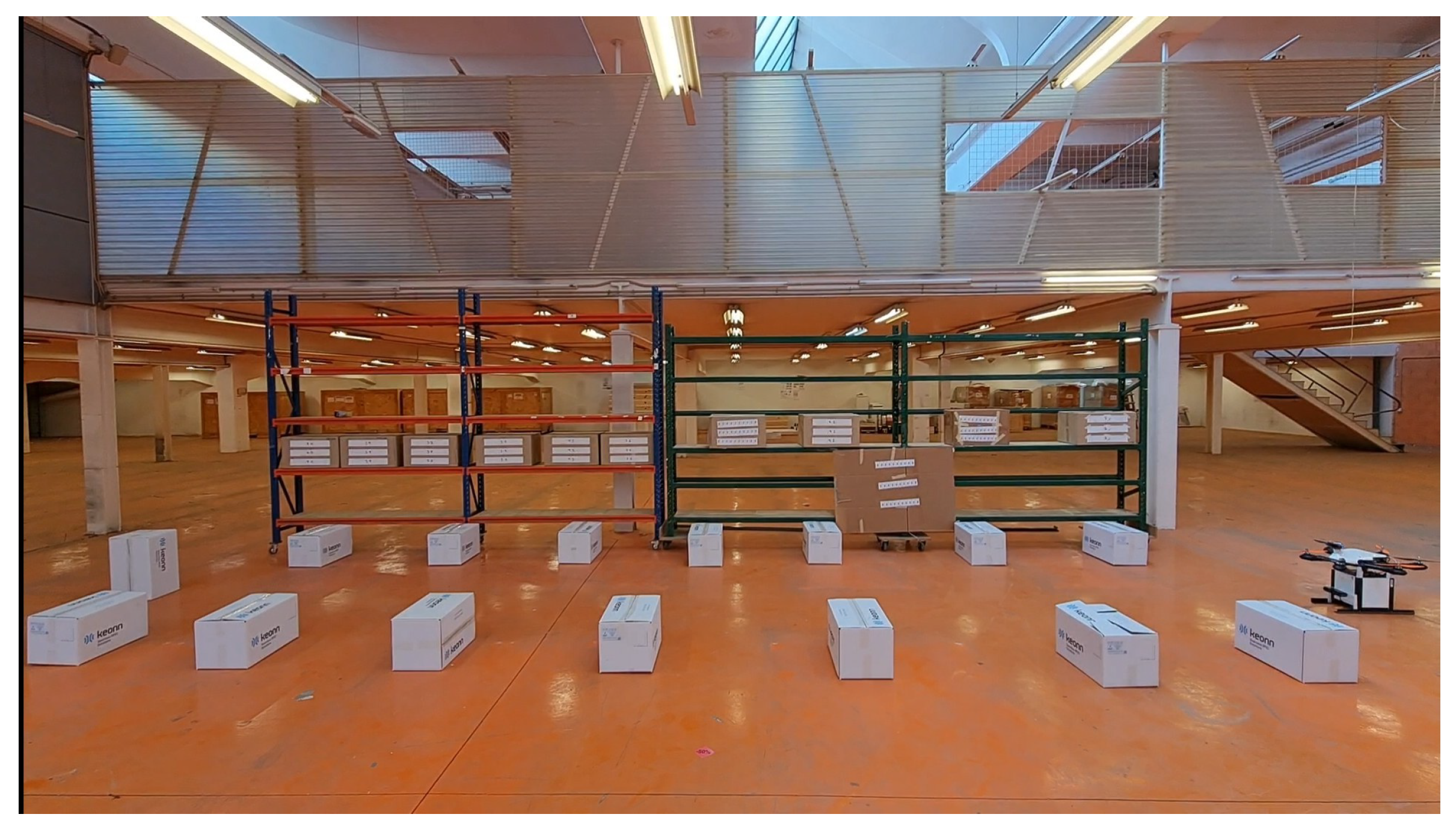
The RFID protocol used by the reader is GEN2 session S0 [27], where the RFID tags in this session will constantly keep responding to the readers request signals as long as they receive one from the reader. This indicates that all of the RFID tags within the coverage range of the antennas will be continuously scanned while the UAV is moving thus, increasing the chance of detection for all of the RFID tags, especially for the tags that are in close range to the antenna.
The algorithm’s inputs are the 4 sets of data after every finite period of time Δ t from each RFID antenna. Each set of data is composed of the sequence of EPC codes from the RFID tags detected for the first time during this time interval, from each antenna. It is worth mentioning that the RFID reader uses a technique called time domain multiplexing (TDM). TDM is a method of transmitting and receiving independent signals over a common signal path by means of synchronized switches at each end of the transmission line so that each signal appears on the line only a fraction of the time in an alternating pattern. This reduces the possibility of cross interference or reading the same RFID tag at the same exact discrete time by two different antennas.
The algorithm will compute a goal message for the UAV, which consists of a target pose message, using the direction of maximum radiation and the number of newly detected RFID tags of each antenna in the time interval, so that the UAV attempts to move to the specified position/orientation in the world following the maximum gradient of newly detected RFID tags.
After computing a goal pose message, the algorithm will request the status of the path toward that goal using the passive OA system. If no obstacle within d distance in the goal direction is detected, the CC will output command signals for the UAV to move in that direction. However, it will still detect if dynamic obstacles are in its path while moving. After reaching the goal, the same process is repeated again. The block diagram in Figure 3 illustrates the RFID-SOAN algorithm used by the UAV.
The new goal pose message/decision ψ n e w is computed as follows. If d 1 , d 2 , d 3 , and d 4 are the following 2D direction vectors shown in Equation (4):
d 1 = ( 1 , 0 ) d 2 = ( 0 , 1 ) d 3 = ( 1 , 0 ) d 4 = ( 0 , 1 )
and group into the direction matrix D shown in Equation (5):
D = d 1 d 2 d 3 d 4
Each of these vectors corresponds to the x, y coordinates of the direction of maximum radiation of each antenna, relative to the front direction of the UAV. Note that d 1 is the front direction. After a time Δ t of reading RFID tags, we obtain a weights vector w = ( w 1 , w 2 , w 3 , w 4 ) , which corresponds to the number of newly detected RFID tags read by each of the RFID antennas during this time interval, as shown in Table 1.
We obtain a new vector V in Equation (6) as the normalized weighted average of the vectors:
V = w · D | w · D |
To obtain the rotation angle θ , we compute the angle between V and the front vector d 1 shown in Equation (7):
θ = arccos V · d 1
The new orientation of the drone ψ n e w is the previous obtained angle plus the computed rotation angle θ shown in Equation (8):
ψ n e w = ψ o l d + θ
In case the UAV does not read new tags in Δ t , it will enter a loop of trying to read new tags in n number of tries n t r i e s set by the user. Once no new tags are read or no sufficient power is left, the UAV will decide to land.

5. Experiments

In logistics, the warehouse product flow determines the overall productivity and efficiency. The design of the warehouse layouts depends on various parameters, such as the available space, product throughput needs, and available resources. Some typical warehouse layouts considered include the U-shaped, I-shaped and L-shaped patterns of shelves. The scenarios that we use to run our experiments use similar patterns of warehouse layouts.
In this section, we show the results of the experiments conducted to test the UAV model and the ability of it to autonomously navigate in an unknown environment toward completing an inventory mission using the RFID-SOAN system. We also compare the inventory results obtained with the results obtained using dead reckoning navigation on the same UAV, where the UAV will navigate with a pre-determined set of positions forming a route or path. To validate the results obtained with both navigation schemes, we first measure, as a base line, the total unique RFID tag readings with the UAV statically positioned and not moving throughout a fixed time duration. This time is equivalent to the duration needed to finish a mission while flying. For all the experiments, the UAV is placed at a distance of 1.75 m from the shelves. We chose this distance carefully considering two important parameters: first, the necessary safety space margin required for the UAV to fly and maneuver as explained before and illustrated in Figure 2; secondly, at this distance, the radiation pattern of the RFID reader is at maximum, and therefore, it will cover a larger area of detection.

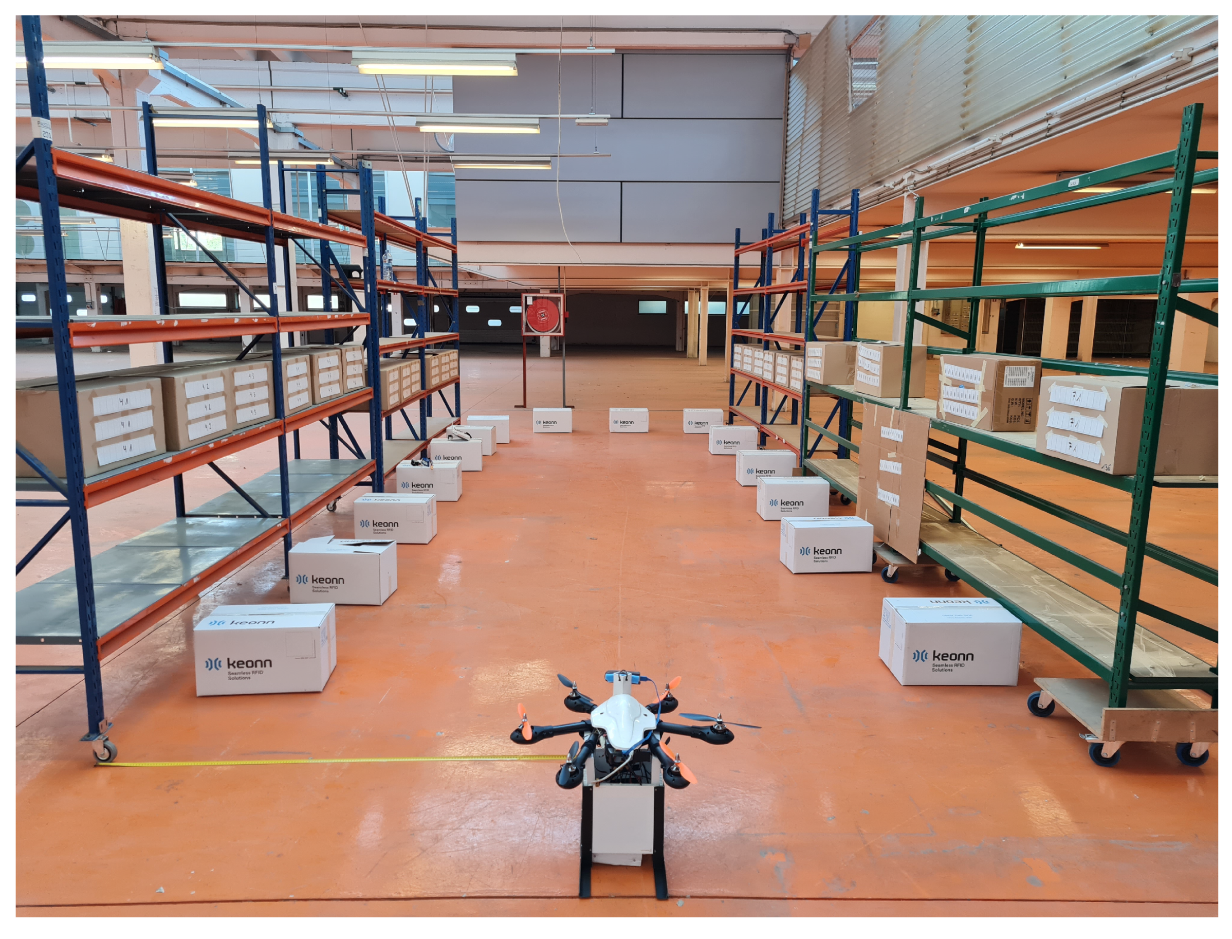
5.1. Scenario 1: One Side, One Aisle, 330 RFID Tags

In Scenario 1, we distribute 330 tags on a 15 m long shelf. Tags are placed in 11 boxes of 30 tags each. These boxes are uniformly horizontally placed throughout the shelf with a fixed altitude of almost 2 m as shown in Figure 4.

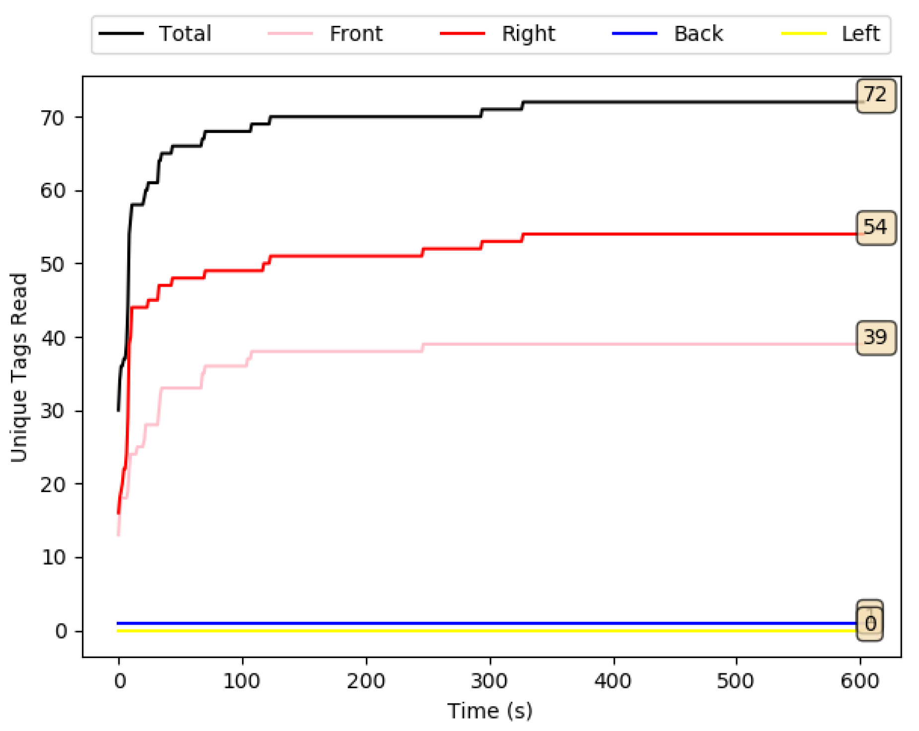
5.1.1. Experiment 1A: Scenario 1, UAV at a Static Position

In Experiment 1A, we want to establish a base line that will be used to compare the effect of the two different navigation strategies (dead reckoning and stigmergy) on the inventory accuracy. For this, we first measure the total unique RFID tags in the environment with the UAV placed in a static position at the starting point for a fixed duration of time. This time should be equal to or greater than the total flight time required for the UAV to complete an inventory mission navigating through Scenario 1, making sure that no more tags can be read. The results of the total tags read as a function of time are shown in Figure 5. Only 21.81% of the tags are read in this experiment.

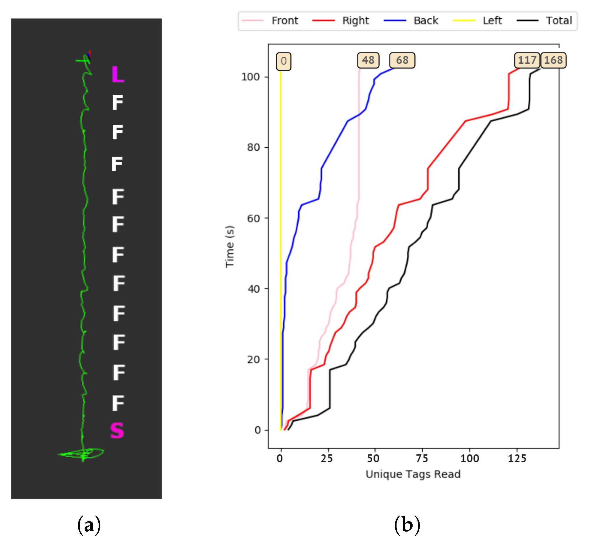
5.1.2. Experiment 1B: Scenario 1, UAV Using Dead Reckoning Navigation

In Experiment 1B, the UAV will navigate in Scenario 1 using dead reckoning in a fixed predefined path alongside the shelf containing tags. This experiment represents the conventional way of pursuing an inventory mission for inventory robots, which requires creating a previous map and establishing a previous set of way-points. For conventional inventory robots, the RFID and the navigation systems operate completely independently of each other. We show the resulting data from this experiment in Figure 6a,b. We can visualize the plots of RFID tag readings with time and the route of the UAV in Rviz. In this experiment, 50.90% of the tags are read, compared to the base line value of 21.81% in Experiment 1A, showing the value of navigation, and hence the need for a UAV. The symbols (TR, TL, F, TB, S, and L) in all the following Rviz illustrations refer to the pose positions, orientations, and actions (Turn Right, Turn Left, Forward, Turn Back, Start and Land).

5.1.3. Experiment 1C: Scenario 1, UAV Using RFID-SOAN Navigation

In Experiment 1C, the UAV will navigate using the proposed RFID-SOAN algorithm through Scenario 1. No prior information of the scenario, including a map or way-points, is supplied to the UAV to aid navigation. We observe from Figure 7a that the UAV was successful at navigating autonomously through the path of new detected tags using the RFID-SOAN algorithm. We show the resulting tags read from this experiment in Figure 7b, where we can see that although the mission takes about twice as long as in Experiment 1B, 96.66% of the tags are read, compared to the 50.90% in Experiment 1B, showing the value of the stigmergy approach and the RFID-SOAN algorithm to increase the accuracy of the inventory. The reason for this time difference is because the UAV decided to turn multiple times trying to explore and navigate toward the highest population density of tags, but was faced with an obstacle each time as shown in Figure 7a. The UAV remains facing the direction of the obstacle if it is still able to read new tags. This ensures that all tags are read before leaving to a new target goal autonomously.

5.2. Scenario 2: Two Sides, One Aisle, 330 Tags

In Scenario 2, we increase the complexity of the environment by placing fixtures on both sides of the aisle as shown in Figure 8, so the UAV will have to navigate through this confined path between two fixtures simulating a close to real warehouse environment.

5.2.1. Experiment 2A: Scenario 2, UAV at a static position

In Experiment 2A, the results of the total tags read as a function of time in Experiment 2A are shown in Figure 9. Only 33.33% of the tags are read in this experiment.

5.2.2. Experiment 2B: Scenario 2, UAV Using Dead Reckoning Navigation

In Experiment 2B, we show the resulting data from this experiment in Figure 10a,b, where we can visualize the plot of RFID tag readings with the time and route of the UAV in Rviz. In this experiment, 48.78% of the tags are read, compared to the base line value of 33.33% in Experiment 2A.

5.2.3. Experiment 2C: Scenario 2, UAV Using RFID-SOAN Navigation

In Experiment 2C, we observe from Figure 11a, that the UAV successfully navigated and explored autonomously the path where the RFID tags were, using the RFID-SOAN algorithm without having any prior information of the environment nor human intervention. We show the RFID tag readings from this experiment in Figure 11b. In this case, the mission takes only 2/3 longer than in Experiment 2B. In Experiment 2C, 97.27% of the tags are read, compared to the 48.78% in Experiment 2B, showing the value of the stigmergy approach and the RFID-SOAN algorithm to increase the accuracy of the inventory.

5.3. Scenario 3: Two Sides, One Aisle, 660 RFID Tags

For Scenario 3, we design a layout to simulate real warehouse aisles, where a robot would have to navigate through aisles surrounding both of its sides with higher RFID tag density. For a UAV, this increases considerably the complexity of the mission, making the UAV navigate autonomously while avoiding obstacles and performing an inventory mission. The goal also is to simulate and analyze the designed UAV behavior in real-life warehouse environments. We increase the tag density to 660 tags, as we can see in Figure 12.

5.3.1. Experiment 3A: Scenario 3, UAV at a Static Position

In Experiment 3A, the results of the total tags read as a function of time are shown in Figure 13. Only 23.78% of the RFID tags are detected in this experiment.

5.3.2. Experiment 3B: Scenario 3, UAV Using Dead Reckoning Navigation

In Experiment 3B, we show the resulting data from this experiment in Figure 14, where we can visualize the plot of RFID tag readings with time. In this experiment, 61.81% of the tags are detected, compared to the base line value of 23.78% in Experiment 3A.

5.3.3. Experiment 3C: Scenario 3 UAV Using RFID-SOAN Navigation

In Experiment 3C, we show the resulting tags read from this experiment in Figure 15, where we can see that in this case, the mission takes about four times as long as in Experiment 3B, which is because the UAV stayed hovering, oriented toward the highest population of tags, and not leaving until a higher density of new tags was detected in another direction and no obstacles lay on the way towards the goal targeted position, which was done autonomously. We can also see that the designed UAV managed to autonomously navigate and explore the map layout where RFID tags exist while performing an inventory mission with no need of a map/way-points nor human intervention. In Experiment 3C, 96.81% of the tags are read, compared to 61.81% in Experiment 3B, showing the value of the stigmergy approach and the RFID-SOAN algorithm to increase the accuracy of the inventory.

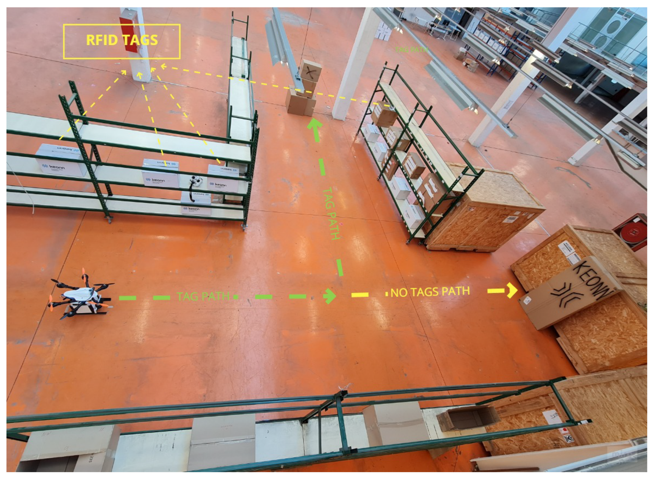
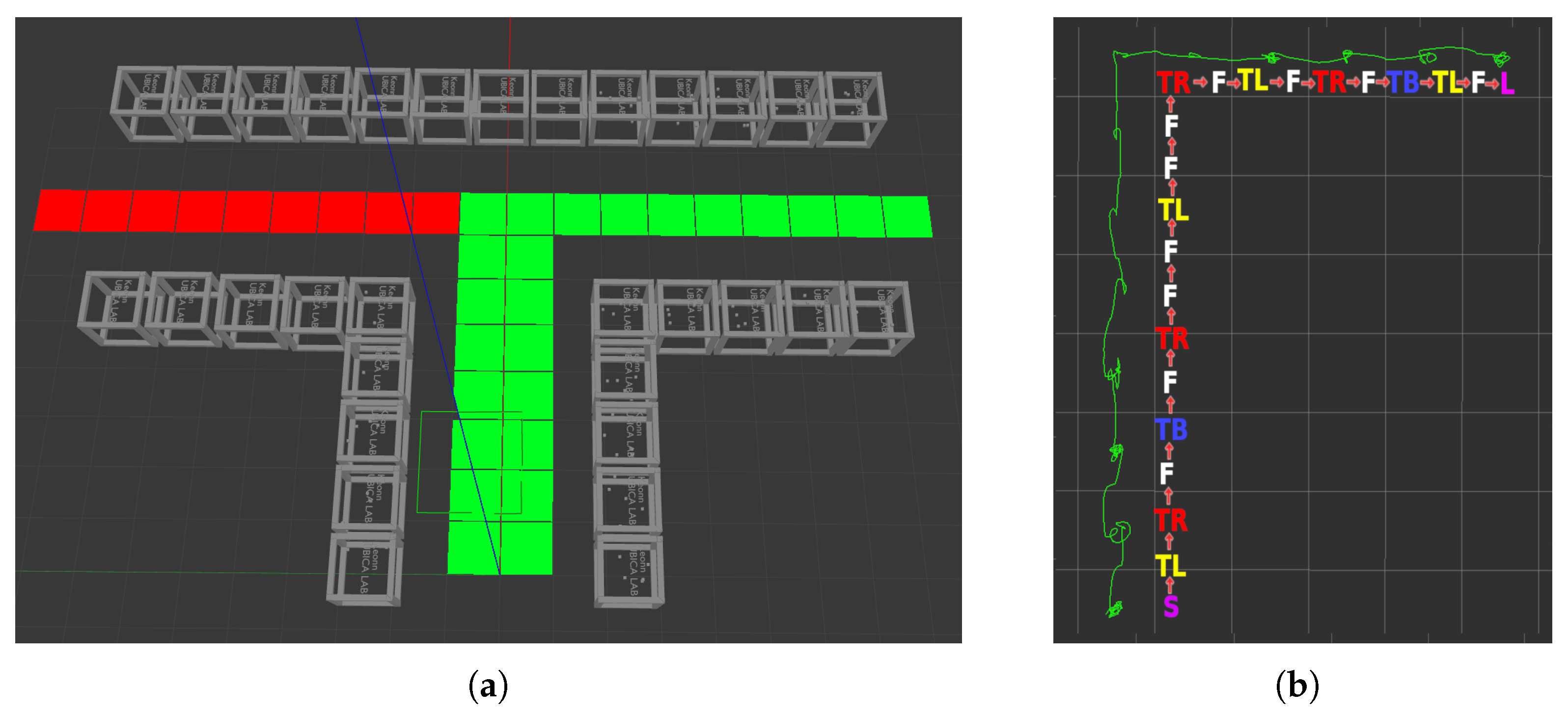
5.4. Scenario 4: Fixtures Forming Two Aisles with a T Shape, Varying Number of Tags

For this final scenario, we try to prove that the RFID-SOAN algorithm can navigate successfully between shelves and around them, meaning that it will navigate through more complex paths, by using the RFID-SOAN algorithm. We design a T-shaped layout, thus, simulating one of the typical warehouse environments used, as we can see in Figure 16, where we show an image of the layout in the lab. For this layout, we decided to perform three different experiments, each with a different tag density (300, 480, 960). The tags are place in the central aisle, and in only one of the lateral aisles. This information is not known to the RFID-SOAN algorithm, which must use the stigmergic approach to navigate and explore the path of the lateral isle that has RFID tags placed on its shelves, while not choosing the path of the other lateral isle with no RFID tags.

5.4.1. Experiment 4A: Scenario 4, RFID-SOAN Navigation, 300 RFID Tags

In Experiment 4A, 300 tags are uniformly distributed in a horizontal manner throughout the T-shaped layout. Figure 17a shows how the UAV chose only the lateral aisle where the tags were placed, ignoring the lateral aisle with no tags in it. Figure 17b, shows how the UAV was able to read 97.33% of all the tags in the environment in about 300 s.

5.4.2. Experiment 4B: Scenario 4, RFID-SOAN Navigation, 480 RFID Tags

In Experiment 4B, 480 tags are uniformly distributed in a horizontal manner throughout the T-shaped layout. Figure 18, shows how the UAV was able to read 97.29% of all the tags in the environment in about 400 s.

5.4.3. Experiment 4C: Scenario 4, RFID-SOAN Navigation, 960 RFID Tags

In Experiment 4C, 960 tags are uniformly distributed in a horizontal manner throughout the T-shaped layout. Figure 19, shows how the UAV was able to read 97.18% of all the tags in the environment in about 700 s.

6. Scenario 5: Simulation

In order to test the RFID-SOAN navigation in longer and more complex map layouts, experiments may become too difficult for a particular lab space, and a particular maximum flight autonomy of the UAV. In these cases, using a simulator, such as the Gazebo [28] ROS [29] simulation environment, may be the best alternative. Gazebo can run the same ROS nodes that are run on the UAV, making the simulation very realistic.

6.1. Experiment 5A: T-Shaped Map Layout

In Experiment 5A, we use an RFID-system plugin [30] that is composed of two sensor plugins: RFID-Tag plugin and RFID-Antenna plugin. The simulated UAV will have the same hardware architecture that we used for the UAV in the lab, and the simulated map layout will be exactly the same as the T-shaped layout that we used for the lab experiments of Scenario 4, in which 300 tags were distributed along the aisle that corresponds to the green line in the simulated layout in Gazebo, shown in Figure 20a. The red squares illustrate the path where no RFID tags are placed on the shelves. The green-colored squares on the grid represent the path that the UAV should take, as RFID-tags are placed and distributed along that path. Finally, a group of RFID-tags is associated with each big grey transparent box in the simulation. Figure 20b shows the Rviz path that the UAV took, which corresponds to the correct path following and considering the direction of the unique RFID tag density. Figure 21 shows the read tags during the whole mission. We observe that, in the simulation, the UAV read about 99.33% of the tags in about 600 s, compared to 97.33% of the tags in 400 s in Experiment 4A (Figure 18), which is in reasonable agreement given the complexity of the environment.

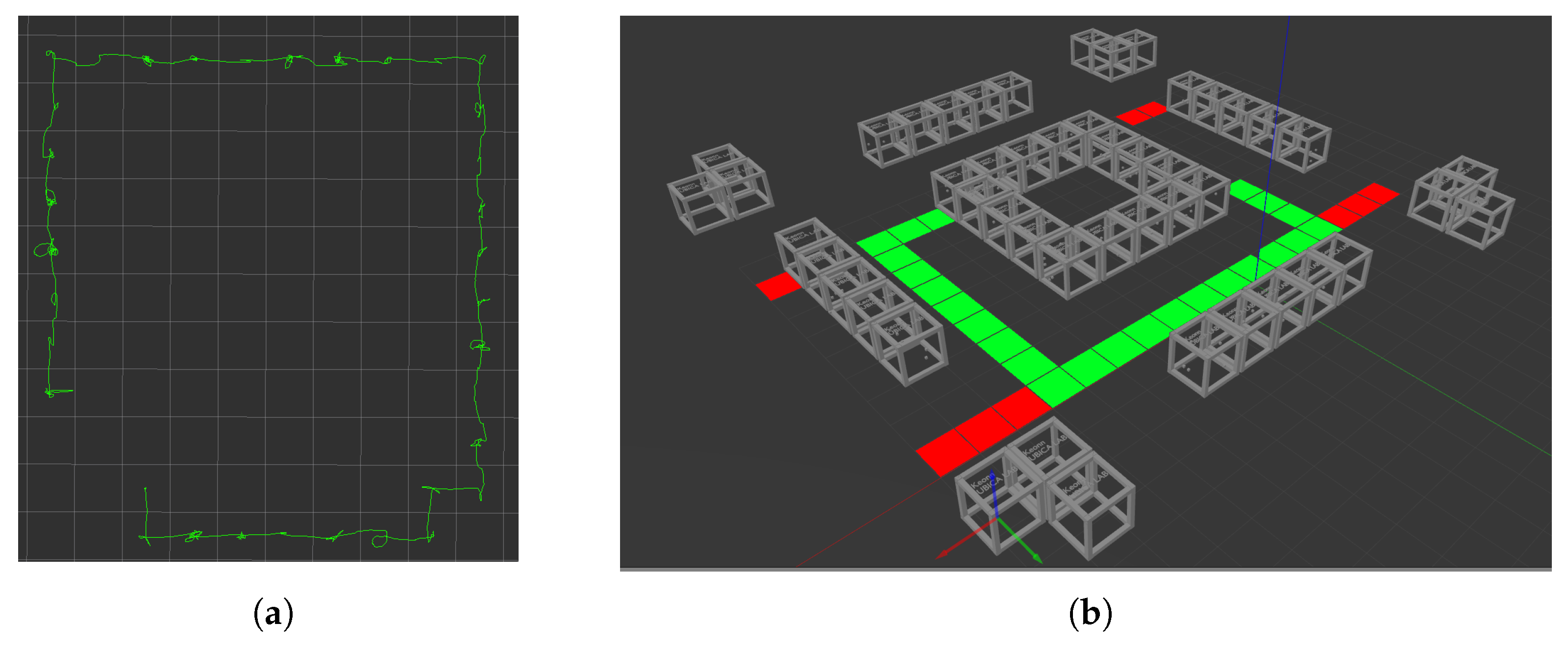
6.2. Experiment 5B: Square Shape Map Layout

In Experiment 5B, we test the map-less navigation and exploration feature of the RFID-SOAN algorithm and the inventory performance in a more complex environment. A square-shaped map layout is used with a much higher population density of tags placed in shelves with very high altitude (6 m) as shown in Figure 22, thus simulating close to real-life warehouse environments, where using a UAV can replace humans performing highly risky tasks. A total of 1700 tags are distributed along the aisle that corresponds to the green line in the simulated layout in Gazebo, shown in Figure 23a. Figure 23b shows the route that the UAV chose in Rviz. From Figure 24 we observe that the UAV read about 96.41% of the tags in about 1300 s, which shows the performance robustness the proposed algorithm, which was able to operate regardless of the tag density and complexity of the environment toward exploring unknown environments by using the existing RFID tags that represent products in warehouses as environmental clues.
In Table 2, we illustrate all the results of the experiments with the UAV navigating using the RFID-SOAN algorithm.
From Table 2, we observe that the designed UAV using the RFID-SOAN algorithm was successful in exploring the correct path where RFID tags exist and not navigating in paths where no RFID tags exist in all of the presented scenarios, doing so without using a reference map or having prior knowledge of the environment.

7. Conclusions

A solution design of a UAV performing dynamic inventory and warehouse exploration in map-less environments autonomously for Industry 4.0 was proposed in this paper. The future goal is to substitute humans performing risky inventory in warehouses containing high shelves with an autonomous UAV. The system proposed can be very useful for exploring RFID-zones in un-mapped or dynamic storage type warehouses, where products are represented by RFID tags, doing so with almost no human intervention, which substantially reduces the operation cost.
Compared to dead reckoning navigation, RFID-SOAN has the distinctive advantage that it does not require any prior knowledge of the environment, nor the need for a map, or establishing a set of predefined way-points.
When left in an environment in which RFID tags are present, the UAV using the RFID-SOAN algorithm will navigate exploring the environment toward the direction in which more new tags are read, covering automatically the parts of the environment in which RFID tags are present. If the distribution of tags changes, the UAV will follow a different path, while dead reckoning would require redefining the way-points.
When compared to a base line in which the UAV was static, and to dead reckoning navigation, RFID-SOAN consistently showed better inventory accuracy in a reasonable time, reaching an accuracy above 96.66% in all conducted experiments.
Compared to dead reckoning, RFID-SOAN will not waste scarce flight time exploring areas devoid of RFID tags.
The simplicity of use, the ability to inventory un-mapped environments, the adaptability with respect to different and changing layouts, and the accuracy in the core inventory task make the RFID-SOAN algorithm a much better navigation alternative than dead reckoning for autonomous inventory UAVs.
The proposed UAV using RFID-SOAN only relies on its own sensors, which means that it does not need modification of the environment or the placement of external sensors for it to navigate autonomously. The sensors used are very cost effective, making the UAV model relatively cheap compared to other proposed models (e.g., in [31]).

8. Future Work

i
Extending the RFID-SOAN algorithm for 3D Navigation. Although the proposed algorithm enables the UAV to read above 96.66% of RFID tags in the scenarios presented, the tags in the ground truth were placed horizontally within a fixed height. This makes it easy for the UAV to read most tags by flying at a fixed altitude. The RFID-SOAN algorithm should be extended to three dimensions, enabling the UAV to inventory tags at different heights. Without this, inventories with tags at different heights must be approached as consecutive 2D inventories at increasing heights. This may require increasing the number of RFID antennas, with the consequent increase in cost and/or decrease in autonomy.
ii
Flight time is considered a major parameter for UAVs, due to the limited size of the power source that they can carry. In order to increase this parameter for the designed UAV, lighter material for antennas and more power efficient RFID readers can be considered.
iii
Robust indoor positioning. We are currently working on making the designed UAV more robust in indoors navigation, using extended sensor fusion to further assure accurate and stable obstacle avoidance while executing an inventory mission.

Author Contributions

Conceptualization, A.A.A.; Formal analysis, G.M.; Funding acquisition, A.A.A.; Investigation, A.A.A.; Methodology, A.A.A.; Project administration, A.A.A. and R.P.; Resources, A.A.A.; Software, A.A.A. and G.M.; Supervision, A.A.A. and R.P.; Validation, G.M.; Visualization, A.A.A.; Writing—original draft, A.A.A.; Writing—review & editing, A.A.A. and R.P. All authors have read and agreed to the published version of the manuscript.

Funding

This research received no external funding.

Institutional Review Board Statement

Not Applicable.

Informed Consent Statement

Not Applicable.

Data Availability Statement

Not Applicable.

Conflicts of Interest

The authors declare no conflict of interest.

References

  1. Fernández-Caramés, T.M.; Blanco-Novoa, O.; Suárez-Albela, M.; Fraga-Lamas, P. A UAV and Blockchain-Based System for Industry 4.0 Inventory and Traceability Applications. Proceedings 2019, 4, 26. [Google Scholar] [CrossRef]
  2. Sholes, E. Evolution of a UAV autonomy classification taxonomy. In Proceedings of the 2007 IEEE Aerospace Conference, Big Sky, MT, USA, 3–10 March 2007; pp. 1–16. [Google Scholar]
  3. Alajmi, A.A.; Vulpe, A.; Fratu, O. UAVs for Wi-Fi receiver mapping and packet sniffing with antenna radiation pattern diversity. Wirel. Pers. Commun. 2017, 92, 297–313. [Google Scholar] [CrossRef]
  4. Audi Media Centre. Audi Uses Drones to Locate Vehicles at Neckarsulm Site. Available online: https://www.audi-mediacenter.com/en/photos/detail/audi-uses-drones-to-locate-vehicles-at-neckarsulm-site-92519 (accessed on 15 June 2022).
  5. Tatum, M.C.; Liu, J. Unmanned aerial vehicles in the construction industry. In Proceedings of the Unmanned Aircraft System Applications in Construction, Creative Construction Conference, Primosten, Croatia, 19–22 June 2017; pp. 19–22. [Google Scholar]
  6. Chen, L.; Plambeck, E.L. Dynamic inventory management with learning about the demand distribution and substitution probability. Manuf. Serv. Oper. Manag. 2008, 10, 236–256. [Google Scholar] [CrossRef]
  7. Heylighen, F. Stigmergy as a Universal Coordination Mechanism: Components, varieties and applications. In Human Stigmergy: Theoretical Developments and New Applications; Springer: New York, NY, USA, 2015. [Google Scholar]
  8. Mason, Z. Programming with stigmergy: Using swarms for construction. In Proceedings of the ICAL 2003: The Eighth International Conference on Artificial Life, Cambridge, MA, USA, 9–13 December 2002; pp. 371–374. [Google Scholar]
  9. Karsai, I. Decentralized control of construction behavior in paper wasps: An overview of the stigmergy approach. Artif. Life 1999, 5, 117–136. [Google Scholar] [CrossRef] [PubMed]
  10. Andrew, A.M. BEHAVIOR-BASED ROBOTICS by Ronald C. Arkin, with a foreword by Michael Arbib, Intelligent Robots and Autonomous Agents series, MIT Press, Cambridge, Mass., 1998, xiv 491 pp, ISBN 0-262-01165-4 (£39.95; Hbk). Robotica 1999, 17, 229–235. [Google Scholar] [CrossRef]
  11. Morenza-Cinos, M.; Casamayor-Pujol, V.; Soler-Busquets, J.; Sanz, J.L.; Guzm, R.; Pous, R. Development of an RFID Inventory Robot (AdvanRobot). In Robot Operating System (ROS): The Complete Reference; Springer International Publishing: Cham, Switzerland, 2017; Volume 2, pp. 387–417. [Google Scholar] [CrossRef]
  12. Ehrenberg, I.; Floerkemeier, C.; Sarma, S. Inventory Management with an RFID-equipped Mobile Robot. In Proceedings of the 2007 IEEE International Conference on Automation Science and Engineering, Scottsdale, AZ, USA, 22–25 September 2007; pp. 1020–1026. [Google Scholar] [CrossRef]
  13. Greco, G.; Lucianaz, C.; Bertoldo, S.; Allegretti, M. A solution for monitoring operations in harsh environment: A RFID reader for small UAV. In Proceedings of the 2015 International Conference on Electromagnetics in Advanced Applications (ICEAA), Turin, Italy, 7–11 September 2015; pp. 859–862. [Google Scholar]
  14. Zhang, J.; Wang, X.; Yu, Z.; Lyu, Y.; Mao, S.; Periaswamy, S.C.; Patton, J.; Wang, X. Robust RFID Based 6-DoF Localization for Unmanned Aerial Vehicles. IEEE Access 2019, 7, 77348–77361. [Google Scholar] [CrossRef]
  15. Eyesee: The Drone Allowing to Automate Inventory in Warehouses. 2016. Available online: http://www.hardis-group.com (accessed on 15 June 2022).
  16. Airborne Data Collection. 2016. Available online: http://dronescan.co (accessed on 15 June 2022).
  17. The Flying Inventory Assistant. 2016. Available online: http://www.fraunhofer.de (accessed on 15 June 2022).
  18. Jhunjhunwala, P.; Shriya, M.; Rufus, E. Development of Hardware based Inventory Management System using UAV and RFID. In Proceedings of the 2019 International Conference on Vision towards Emerging Trends in Communication and Networking (ViTECoN), Vellore, India, 30–31 March 2019; pp. 1–5. [Google Scholar] [CrossRef]
  19. Kwon, W.; Park, J.H.; Lee, M.; Her, J.; Kim, S.H.; Seo, J.W. Robust autonomous navigation of unmanned aerial vehicles (uavs) for warehouses’ inventory application. IEEE Robotics Autom. Lett. 2019, 5, 243–249. [Google Scholar] [CrossRef]
  20. Bae, S.M.; Han, K.H.; Cha, C.N.; Lee, H.Y. Development of inventory checking system based on UAV and RFID in open storage yard. In Proceedings of the 2016 International Conference on Information Science and Security (ICISS), Pattaya, Thailand, 19–22 December 2016; pp. 1–2. [Google Scholar]
  21. Susnea, I.; Vasiliu, G.; Filipescu, A.; Serbencu, A.; Radaschin, A. Virtual pheromones to control mobile robots. A neural network approach. In Proceedings of the 2009 IEEE International Conference on Automation and Logistics, Shenyang, China, 5–7 August 2009; pp. 1962–1967. [Google Scholar] [CrossRef]
  22. Khaliq, A.A. From Ants to Service Robots: An Exploration in Stigmergy-Based Navigation Algorithms. Ph.D. Thesis, Örebro University, Örebro, Sweden, 2018. [Google Scholar]
  23. Khaliq, A.A.; Saffiotti, A. Stigmergy at work: Planning and navigation for a service robot on an RFID floor. In Proceedings of the 2015 IEEE International Conference on Robotics and Automation (ICRA), Seattle, WA, USA, 26–30 May 2015; pp. 1085–1092. [Google Scholar]
  24. Casamayor-Pujol, V.; Morenza-Cinos, M.; Gastón, B.; Pous, R. Autonomous stock counting based on a stigmergic algorithm for multi-robot systems. Comput. Ind. 2020, 122, 103259. [Google Scholar] [CrossRef]
  25. Keonn’s AdvanReader 160. Available online: https://keonn.com/components-product/advanreader-160/ (accessed on 15 June 2022).
  26. Keonn’s AdvantennaSP11. Available online: https://keonn.com/components-product/advantenna-sp11/ (accessed on 15 June 2022).
  27. GEN. 2 RFID Protocol Gen. 2. Available online: https://www.gs1.org/epc-rfid (accessed on 15 June 2022).
  28. Koenig, N.; Howard, A. Design and use paradigms for gazebo, an open-source multi-robot simulator. In Proceedings of the 2004 IEEE/RSJ International Conference on Intelligent Robots and Systems (IROS)(IEEE Cat. No. 04CH37566), Sendai, Japan, 28 September–2 October 2004; Volume 3, pp. 2149–2154. [Google Scholar]
  29. Koubâa, A. Robot Operating System (ROS); Springer: Berlin/Heidelberg, Germany, 2017; Volume 1. [Google Scholar]
  30. Alajami, A.; Moreno, G.; Pous, R. RFID-Sensor Gazebo Plugin. ROS Wiki. 2022. Available online: http://wiki.ros.org/RFIDsensor_Gazebo_plugin (accessed on 15 June 2022).
  31. Beul, M.; Droeschel, D.; Nieuwenhuisen, M.; Quenzel, J.; Houben, S.; Behnke, S. Fast Autonomous Flight in Warehouses for Inventory Applications. IEEE Robots Autom. Lett. 2018, 3, 3121–3128. [Google Scholar] [CrossRef]
Figure 1. Hardware block diagram of the UAV.
Drones 06 00208 g001
Figure 2. An illustration of the OA system parameters.
Drones 06 00208 g002
Figure 3. RFID-SOAN navigation algorithm workflow and block diagram.
Drones 06 00208 g003
Figure 4. Lab setup of Scenario 1.
Drones 06 00208 g004
Figure 5. Scenario 1, Experiment 1A: total RFID tag readings vs. time from a static position equal to the starting point.
Drones 06 00208 g005
Figure 6. Scenario 1, Experiment 1B: path shown on Rviz and total RFID tag readings vs. time when the UAV uses dead reckoning navigation. (a) UAV path in Rviz. (b) Unique RFID tags read vs. time.
Drones 06 00208 g006
Figure 7. Scenario 1, Experiment 1C: path shown on Rviz and total RFID tag readings vs. time when the UAV uses RFID-SOAN navigation. (a) UAV path in Rviz. (b) Unique RFID tags read vs. time.
Drones 06 00208 g007
Figure 8. Lab setup of Scenario 2.
Drones 06 00208 g008
Figure 9. Scenario 2, Experiment 2A: total RFID tag readings vs. time from a static position equal to the starting point.
Drones 06 00208 g009
Figure 10. Scenario 2, Experiment 2B: path shown on Rviz and total RFID tag readings vs. time when the UAV uses Dead Reckoning navigation. (a) UAV path in Rviz. (b) Unique RFID tags read vs. time.
Drones 06 00208 g010
Figure 11. Scenario 2, Experiment 2C: path shown on Rviz and total RFID tag readings vs. time when the UAV uses RFID-SOAN navigation. (a) UAV path in Rviz. (b) Unique RFID tags read vs. time.
Drones 06 00208 g011
Figure 12. Lab setup of Scenario 3.
Drones 06 00208 g012
Figure 13. Scenario 3, Experiment 3A: total RFID tag readings vs. time from a static position equal to the starting point.
Drones 06 00208 g013
Figure 14. Scenario 3, Experiment 3B: total RFID tag readings vs. time when the UAV uses dead reckoning navigation.
Drones 06 00208 g014
Figure 15. Scenario 3, Experiment 3C: total RFID tag readings vs. time when the UAV uses RFID-SOAN navigation.
Drones 06 00208 g015
Figure 16. Laboratory images of Scenario 4.
Drones 06 00208 g016
Figure 17. Scenario 4, Experiment 4A: path shown in Rviz and tags read vs. time, with the UAV using RFID-SOAN navigation in a T-shaped environment in which 300 RFID tags were placed. (a) UAV path in Rviz. (b) Unique RFID tag readings.
Drones 06 00208 g017
Figure 18. Scenario 4, Experiment 4B: tags read vs. time, with the UAV using RFID-SOAN navigation in a T-shaped environment in which 480 RFID tags were placed.
Drones 06 00208 g018
Figure 19. Scenario 4, Experiment 4C: tags read vs. time, with the UAV using RFID-SOAN navigation in a T-shaped environment in which 960 RFID tags were placed.
Drones 06 00208 g019
Figure 20. Scenario S1: T-shaped layout and path followed by the UAV. (a) Top view of the simulation layout. (b) UAV chosen path in Rviz.
Drones 06 00208 g020
Figure 21. Scenario S1: tags read vs. time, with the UAV using RFID-SOAN navigation in a T-shaped environment in which 300 RFID tags were placed.
Drones 06 00208 g021
Figure 22. Experiment 5B: A gazebo illustration showing the height of a fixture shelve in the square shape map layout.
Drones 06 00208 g022
Figure 23. Experiment 5A: T-shaped layout and path followed by the UAV. (a) UAV chosen path in Rviz. (b) Side view of the simulation layout.
Drones 06 00208 g023
Figure 24. Experiment 5B: tags read vs. time, with the UAV using RFID-SOAN navigation in a square-shaped environment in which 1700 RFID tags were placed.
Drones 06 00208 g024
Table 1. Orientation vector and weight of each RFID antenna.
Antenna Dir.VectorWeight
Front d 1 w 1
Right d 2 w 2
Back d 3 w 3
Left d 4 w 4
Table 2. Illustrates the results of all the experiments conducted with the UAV using the RFID-SOAN algorithm.
ExperimentMap-LayoutNum. Tags in MapRFID Path ExplorationRead Tags
1C1-side/1-isle330Successful96.66%
2C2-sides/1-isle330Successful97.27%
3C2-sides/1-isle660Successful96.81%
4AT-shape300Successful97.33%
4BT-shape480Successful97.29%
4CT-shape960Successful97.18%
5AT-shape300Successful99.33%
5BSquare-shape1700Successful96.41%
Publisher’s Note: MDPI stays neutral with regard to jurisdictional claims in published maps and institutional affiliations.

