Article

Flow-Induced Force Modeling and Active Compensation for a Fluid-Tethered Multirotor Aerial Craft during Pressurised Jetting

1
Engineering Product Development (EPD), Singapore University of Technology and Design, Singapore 487372, Singapore
2
Department of Mechanical Engineering & Temasek Laboratories, National University of Singapore, Singapore 119077, Singapore
*
Author to whom correspondence should be addressed.
These authors contributed equally to this work.
Drones 2022, 6(4), 88; https://doi.org/10.3390/drones6040088
Submission received: 28 February 2022 / Revised: 21 March 2022 / Accepted: 22 March 2022 / Published: 28 March 2022

Abstract

:
This paper presents an investigation of the fluid–structure interaction (FSI) effects on the stability of a quadrotor attached to a flexible hose conveying and ejecting pressurised fluid from an onboard nozzle. In this study, an analytical solution is derived to obtain the time and spatial responses of the free end, which could affect the quadrotor’s stability. First, the flow-induced force model was simulated at the hose plane to find out the contributing disturbances prior to the physical connection with the unmanned aerial vehicle (UAV). Thereafter, the flow-induced forces were introduced to the UAV dynamics model as disturbances to study the FSI response during flight. Physical experiments were conducted to compare the analytical responses of the UAV prior to and during ejection. The presented findings of the perturbations due to the FSI effect from the pressurised fluid flowing through the flexible hose to the free end and the jet reaction at the UAV nozzle will be used for the employment of a combined feedforward-feedback (FF-FB) quadrotor control strategy for a stable ejection phase. The proposed strategy shows an average improvement of 61.14% (x-axis) and 22.46% (z-axis) in terms of active position compensation during ejection as compared to a standard feedback (FB) control loop only.

1. Introduction

With the advancement of technology, robotic platforms such as the multirotor aerial craft, also known as an unmanned aerial vehicle (UAVs), are disrupting traditional industries in the high-rise maintenance (inspection and cleaning) sector. Due to a UAV’s vertical takeoff and landing capability, ability to navigate in severe environments, and payload augmentation, increasing numbers of UAVs are employed to assist in dangerous and difficult manual maintenance operations. These purpose-built UAVs modernise traditional methods of setting up mechanised elevated work platforms (MEWPs) or scaffolds in order to inspect or clean structures at a height. UAVs serve as a convenient medium to extend the reach of sensors or payload to the desired operating position.
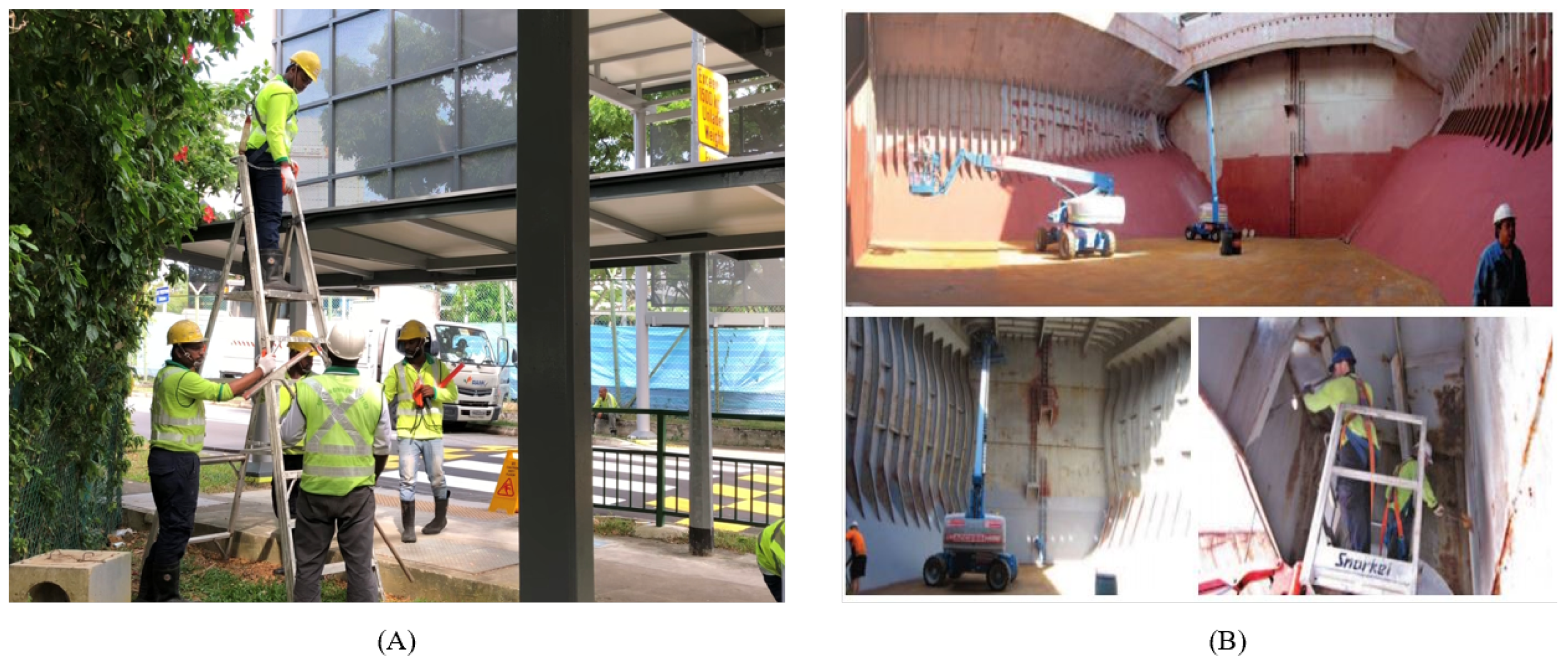
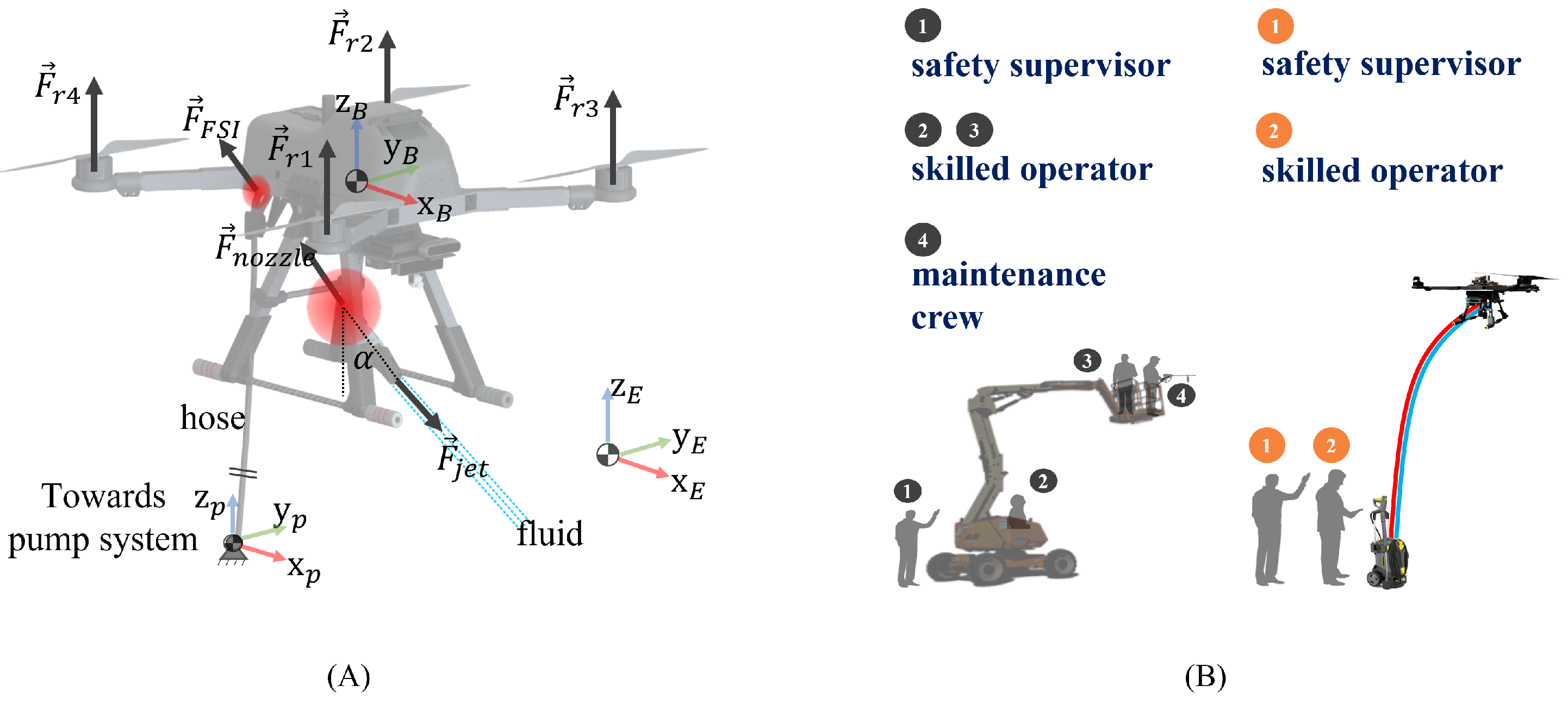
Many commercial-off-the-shelf (COTS) UAVs are able to carry an onboard camera-gimbal system, providing a stable level horizon, which makes high-rise inspection with UAVs a default solution for many users. On the other hand, fluid ejection UAVs are still uncommon, as there is no readily available gimbal for nozzles. There are past works that explored low-volume spraying [1,2], as well as high-rise maintenance works that employ the use of a UAV [3,4,5]. In the applications of clustered built-environment spaces, such as structural cleaning and bulk carrier cargo hold maintenance, regular cleaning maintains the safety standards for public use and for switching from mineral cargo to food cargo, respectively. The current cleaning methods shown in Figure 1 demonstrate the manual intensity and need for assisted equipment. Therefore, the use of cleaning robots is highly beneficial, as current solutions are extremely manual and rely heavily on the use of MEWPs to reduce the standoff distance of the fluid ejection for more effective cleaning. As illustrated in Figure 2, UAV solutions also help to eliminate the need for any humans to work from heights and reduce the amount of manpower needed in a single cleaning operation.
Besides the reduction of manpower and risk, a UAV equipped with a high-pressure water jet provides flexibility in cleaning hard-to-reach areas without the need to be in close proximity to buildings with complex geometries or facades where employment of MEWPs may not be feasible. Furthermore, employment of UAVs in cleaning applications can increase operational efficiency; unlike typical MEWP operations, which require coordination between 2–3 operators, the UAV control and cleaning application can be done semi-autonomously and remotely by an operator. However, with high-pressure fluid ejection, the UAV will be subjected to flow-induced forces that push the UAV in the opposite direction of ejection. Without a stable ejection phase, the adoption of such solutions are still low due to the fear of collision. In situations such as localised cleaning, analysis of the external perturbations acting on the UAV during the ejection phase from the jet ejection is critical, as the resulting drift may lead to undesirable positioning of the point of contact of the fluid. Furthermore, excessive drift imposes a constraint on the available operating area, particularly in clustered environments.
An interesting aspect of fluid ejection was presented by [6] by studying the hybrid kinematics modelling for accurate jetting onto targets. An aerial-hose-type robot was developed by [7,8] by exploiting fluid jet propulsion for elevation, coupled with control valve mechanisms to regulate the jet flow for lateral and frontal motion. However, none of these prior works studied the flow-induced forces acting upon the UAVs and how they might affect its stability.
With the involvement of fluid ejection in a tethered setup, the free end of the hose that is connected to any pseudo-fixed platform will be subjected to a phenomenon known as fluid–structure interaction (FSI). There are past works that have studied the FSI effects of a pipe conveying fluid in a cantilevered arrangement, as described in [9,10,11]. While all of them are in a cantilevered arrangement, [9] has a converging cantilevered pipe towards the free end, [10] has the pipe suspended by its fixed point, and [11] investigates the scenario of constrained pipes. In addition, [12] discussed the effects of varying flow velocity on the end-mass of a single straight or articulated pipe. The stability of the flow-induced perturbations is dependent on the critical pipe in-flow velocity U c r i t , which increases as larger end-masses are used [13]. Considering constant and variable flow velocities, [14] studied the fluttering observed in a cantilevered system, as well as additional buckling in simple supported systems.
To visualise this effect, one end of the hose is connected to the pressure pump system, with the other end of the pipe extended and laying freely (free end). As the fluid flows through the hose, the free end is expected to ’whip’ around. For a fluid-ejecting UAV, as shown in Figure 2, the free end of the hose is attached to the platform, and this translates to a ’whipping’ effect on the UAV. The translated effect, combined with the jet reaction, can be destructive to the UAV’s stability if it is not carefully studied and mitigated. An improved controller was introduced by [15] by employing FF control to stabilise the UAV; however, the system is small and it uses fluid as a medium for propulsion. On the other hand, [16,17] explored mechanical means like thrusters and flow re-direction to aid the stability of the UAV in flight. Even though all of these works employ a tethered concept, the authors did not study the flow-induced effects on their UAV, which could affect the stability without external excitation. With knowledge of the flow-induced disturbance model acting on the UAV system, corrective methods can be better implemented.
Therefore, this paper focuses on the study of the flow-induced forces acting on a pseudo-fixed end-mass, that is, a hovering UAV with the free end of the flexible hose tethered to it. In order to utilise the FSI effects and jet reaction for a constructive purpose, this paper investigates the effects of this interaction between the free end of the hose attached to the pseudo-fixed end-mass in terms of its time and spatial responses. Thereafter, this knowledge is applied to the control scheme of the UAV to ensure the stability of the platform during fluid ejection. Modifications to the UAV control scheme will be introduced, which include the employment of an FF-FB controller. The flow-induced forces will be assumed as disturbances for UAV position correction.
Section 2 addresses the flow-induced dynamic models and Section 3 will cover the UAV control system and the FF-FB strategy. Section 4 and Section 5 will present the simulations and experimental validations, respectively. Section 6 will present the conclusion and future works. In this paper, a variable with subscript B indicates that the variable is represented in the body-fixed frame B . Otherwise, the variable is in the earth-fixed frame E . All variables for angles are described in degrees (°).
In summary, the niche of this paper is the approximation of the flow-induced effects from the fluid supply and discharge segments on the UAV platform. Subsequently, these flow-related forces are treated as disturbances to the UAV platform, and the proposed control strategy is applied to mitigate these flow-induced effects.

2. UAV Concept and Flow-Induced Dynamic Models

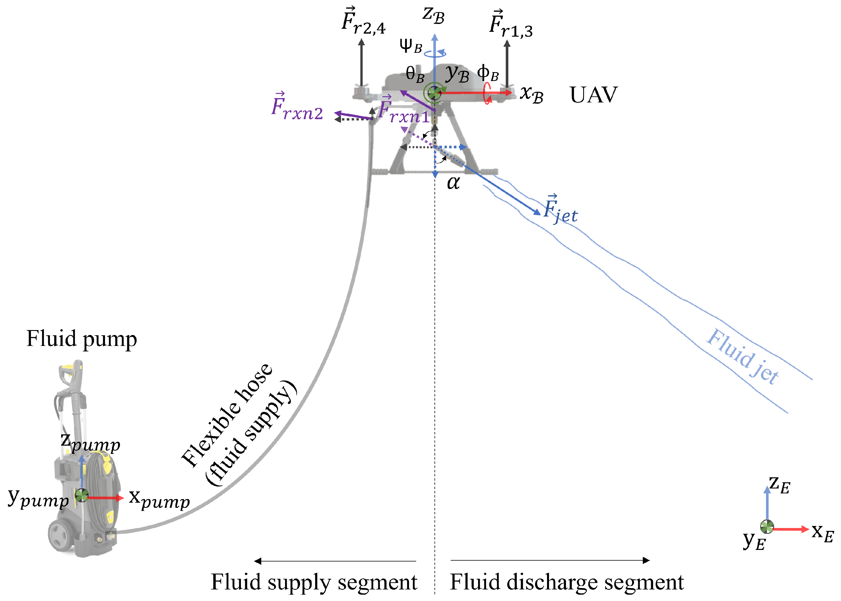
In this section, the consideration of the combined FSI effect on the UAV comes from (1) fluid supply and (2) fluid discharge, as shown in Figure 3. The UAV is assumed to be operating in a still air environment, and as such, the effect from the ambient airflow is negligible.
At the fluid supply segment, pressurised fluid from the water pump flows through the fixed end of the flexible hose to the free end. At the free end, the flexible hose is expected to displace aggressively in the axial direction, causing push and pull forces on the point mass, which can be estimated analytically. As the flexible hose is connected to the UAV, this flow-induced (destructive) force is translated on the UAV as unnecessary perturbations to overcome.
At the fluid discharge segment, the pressurised jet flow exiting the nozzle will produce a reaction force on the UAV at the direction opposite to the jet flow. The reaction force can be derived with the estimation of the jet velocity. Similarly, the reaction force will also contribute to the destructive force for the UAV to overcome.

2.1. Fluid Supply Segment

Figure 4 shows a schematic diagram of the water supply hose at the fluid supply side. The water hose is of finite length L along the hose’s axial coordinate.
This water supply hose can be modelled as a cantilevered flexible hose with fixed-free supports, which can be mathematically modelled by applying a variation method [9,11,12,18]. In this paper, the approach by [19], further improved by [12], is applied. The classic governing equation for dynamic response vibration [20] is described as:
E I 4 w x 4 + m h U 2 2 w x 2 + ( 2 m h U ) 2 w x t + ( m h + m f ) 2 w t 2 = 0 ,
where E I ( x ) is the hose’s flexural rigidity, L is the hose’s length, U is the fluid flow velocity along the axial span, m h and m f are the hose and fluid mass, and w ( x , t ) represents the lateral displacement (vibration) of the hose and is the sought output. The gravity, internal damping, externally imposed tension, and pressurisation effects are usually neglected, as their effects are either static or absent [10,11,12,21].
Equation (1) is in dimensional form. We define the dimensionless parameters as W = w L , X = x L , T = t L 2 E I m h + m f . In addition, let β * = m h / m f , ω = L 2 Ω m h + m f E I , where Ω is the complex circular frequency. The non-dimensional governing equation becomes:
4 W X 4 + 4 U 2 π 2 W X 2 + 4 β U i ω π 2 W X T + 2 W T 2 = 0 ,
where β = 1 1 + 2 β * ( h ¯ / a ) , h ¯ is the thickness of the hose, and a is the outer diameter of the hose. The complete solution of the traverse displacement is in the form of W ( x , T ) = ϕ ( x ) e i ω T . The time and spatial responses can be solved separately.
Equation (2) has been analysed by many prior researchers for straight traverse pipes (e.g., [9,12,14,21,22]), and thus, the solutions W ( x , T ) for straight and level pipe setting (see Figure 4) have been well established. However, the setup in this work is markedly different from those existing solutions. In this application, the end of the discharge hose (pipe) is always held at different heights from the water supply side (from the fluid pump) by the UAV (see Figure 3). Hence, the spatial response for this pipe with a different end level case will be different from the usual straight and level pipe case, and it needs to be uniquely analysed. Nevertheless, the time response will still be the same in both cases. The outcome of the time response will be presented first in the next section. Then, the detailed derivation and analysis of the spatial response for this specific pipe with different end level cases will be presented in the subsequent section.

2.1.1. Time Response

As mentioned, the time responses have been solved by many researchers in the past, as reported in the literature. The goal is to solve for the complex circular frequency ( ω ) and to study the stability condition and establish the instability threshold. Here, we emulate and adopt the works by Gregory and Paidoussis [22] and Gaith [9]. In these works, the time response was solved by Galerkin’s method to obtain the solutions together with the experimental data. The first row of nominal natural frequencies solutions corresponding to the first two mode shapes (fundamental and first harmonic) for the case of β = 0.2 , as reported in [22].
Ref. [22] states that the imaginary part of the natural frequency for the second mode shape, I m ( ω 2 ) is negative from u ≥ 6 m/s onwards. This means that the combined solution W ( x , T ) = Σ ω ϕ ( x ) e i ω T will grow exponentially and becomes unstable. Thus, this establishes the maximum velocity limit for stable fluid discharge operation. The simulation result will be illustrated later in the Combined Response section.

2.1.2. Spatial Response

Since the geometry setup in this work is unique, that is, the discharge end is at different heights from the supply end at all times, as shown in Figure 3, the spatial response will be different from the typical straight and level pipe case and needs to be derived.
For each frequency ω , we solve for the dimensionless spatial response ϕ ( x , ω ) individually. The total solution will be the superposition of all ϕ ( x , ω ) from all ω . Typically, the first two frequencies are used (i.e., ω 1 and ω 2 ) [9,18]. Using the non-dimensional governing Equation (2) and W ( x , T ) = Σ ω ϕ ( x ) e i ω T , the equation for spatial response becomes:
d 4 ϕ d x 4 + B d 2 ϕ d x 2 + C d ϕ d x + D ϕ = 0 ,
where B = 4 U 2 π , C = 4 β U i ω π , and D = ω 2
This is the linear fourth-order ordinary differential equation. The solution can be in the form of ϕ ( x ) = e λ x . Upon substitutions, Equation (3) becomes the characteristic equation for eigenvalues λ .
λ 4 + B λ 2 + C λ + D = 0 ,
Equation (4) is the characteristic equation for finding eigenvalues λ , which can be done by computer-aided numerical methods. The solutions for each ϕ ( x , ω ) are the superpositions of four eigenvalues λ , that is, ϕ ( x ) = c 1 e λ 1 x + c 2 e λ 2 x + c 3 e λ 3 x + c 4 e λ 4 x , where c 1 ,   c 2 ,   c 3 , and c 4 are constants subjected to initial and boundary conditions.
The full dimensionless time and spatial response, W, is represented by W ( X , T ) = Σ ω ϕ ( X ) e i ω T . The initial and boundary conditions are:
  • No displacement at the fixed supply end: x = 0 , that is, W ( x = 0 , T ) = ϕ ( x = 0 ) e i ω T = 0 ; hence, ϕ ( x = 0 ) = 0 .
  • No slope and no bend at the fixed supply end: x = 0 , that is, d W ( x = 0 , T ) d x = d ϕ ( x = 0 ) d x e i ω T = 0 ; hence, d ϕ ( x = 0 ) d x = 0 .
  • No force at the fixed supply end: x = 0 , that is, d 2 W ( x = 0 , T ) d x 2 = d 2 ϕ ( x = 0 ) d x 2 e i ω T = 0 ; hence, d 2 ϕ ( x = 0 ) d x 2 = 0 .
  • Initial displacement at the free discharge end: x = L at time T = 0 is h (physical height), that is, W ( x = L , T = 0 ) = ϕ ( x = L ) e i ω 0 = H , where H is dimensionless height and H h / L ; hence ϕ ( x = L ) = H .
From these four conditions, we can formulate the matrix and solve for c 1 ,   c 2 ,   c 3 , and c 4 , that is,
1 1 1 1 λ 1 λ 2 λ 3 λ 4 λ 1 2 λ 2 2 λ 3 2 λ 4 2 e λ 1 L e λ 2 L e λ 3 L e λ 4 L c 1 c 2 c 3 c 4 = 0 0 0 H ,
Likewise, this can be done by numerical methods for matrix inversion. As there will be multiple frequencies, the overall solutions will be the superpositions of the solutions for all frequencies, that is,
W ( x , T ) = Σ ω ϕ ( x , ω ) e i ω T = { c 1 e λ 1 x + c 2 e λ 2 x + c 3 e λ 3 x + c 4 e λ 4 x } ω 1 e i ω 1 T + { c 1 e λ 1 x + c 2 e λ 2 x + c 3 e λ 3 x + c 4 e λ 4 x } ω 2 e i ω 2 T + . . .
Note that these parameters (i.e., ω , λ , ϕ , etc.) are complex numbers. The critical point is when the real part of e i ω 2 T becomes positive. Then, the displacement response w ( x , T ) will grow exponentially out of bound with time, as explained in the previous Time Response section. This happens when the imaginary part of ω becomes negative. Recalling [22], this divergence starts from the critical flow velocity U c r i t = 6 m/s onwards for first harmonic ω 2 .

2.1.3. Combined Response

With the outcomes for both time and spatial responses, we can get the combined response for hose vertical (traverse) displacement, W ( x , T ) = Σ ω ϕ ( x , ω ) e i ω T . The work flow is shown in these calculation steps:
  • Input flow velocity (water supply), U;
  • Recall the natural frequencies ω = Re( ω ) + i*Im ( ω ) from [22];
  • For each natural frequency ω j , j = 1, 2, …, calculate the coefficients B , C , and D in Equation (3), and solve for four eigenvalues λ j , j = 1, 2, 3, and 4 using Equation (4);
  • Solve for the four coefficients, c j , j = 1, 2, 3, and 4 for ϕ ( x ) using Equation (5);
  • Repeat steps 3 and 4 for the next natural frequency ω j .
Then, the vertical force caused by the hose’s vertical (traverse) displacement at the hose end ( x = L ) can be obtained from
F h o s e ( x = L , t ) = ( m h + m f ) 2 w ( x = L , t ) t 2 ,
From which 2 w ( x = L , t ) t 2 can be calculated from
2 w ( x = L , t ) t 2 = 1 L 3 E I m h + m f 2 W ( x = L , T ) T 2 ,
that is, conversion from non-dimensional ( X , T , and W) back to dimensional variables ( x , t , and w). Using the solution of W ( x = L , T ) , we get
2 W ( x = L , T ) T 2 = Σ ω ϕ ( x = L , ω ) ω 2 e i ω T .
Thereafter, we have
F h o s e ( x = L , t ) = E I L 3 Σ ω ϕ ( x = L , ω ) ω 2 e i ω T .
Figure 5A illustrates this cantilevered hose ejecting fluid from a suspended free end. The dotted region encapsulates the configuration space for the free end of the hose when subjected to the FSI force only. Since the FSI force is expected to be planar at the free end, it would have a periodic oscillation upon fluid ejection. These oscillations will be transferred onto the UAV, but with a magnitude that can be easily handled by the natural damping term of the respective UAV state space equations and its FB controller.

2.2. Fluid Discharge Segment

Fluid Jet Force

Figure 5B shows the schematic diagram at the discharge segment for a range of jetting force between 0° and 90°. The UAV is equipped with the flexible hose to convey and discharge fluid out to the ambient surroundings. With this arrangement, there will be a reactive force caused by the fluid jet. Such a reactive force can be estimated, provided that the jet exit velocity and jet initial pressure (pump pressure system) are known.
There have been numerous studies on jet exit velocities [23]. Urazmetov et al. [24] came up with an empirical formula based on initial jet pressure. Note that as water becomes slightly compressible at a sufficiently high pressure, the velocity calculation will be affected by the compressibility.
v j e t = 2 n K 0 ρ 0 ( 1 n ) { ( 1 + p n K 0 ) 1 n 1 } ,
where ρ 0 is the standard fluid (water) density at 25 °C at 1 atm = 997 kg/m 3 , n is the density exponent, and K 0 is the reference bulk modulus. At p = 12 MPa, n = 7.15 and K 0 = 2.2 GPa.
As the exit jet discharges to the ambient pressure and open air, we can calculate the corresponding reactive force from momentum equation, which gives
F j e t = ρ Q v j e t = ( ρ V A ) v j e t + ( P j e t P a m b i e n t ) A ,
where Q is the discharge volume flow rate, ρ is the fluid (water) density, A is the cross-sectional area of the nozzle exit, P j e t is the jet pressure, and P a m b i e n t is the ambient pressure.
Based on the the current setup, the jet pressure, jet exit velocity, and jet force are shown in Table 1.
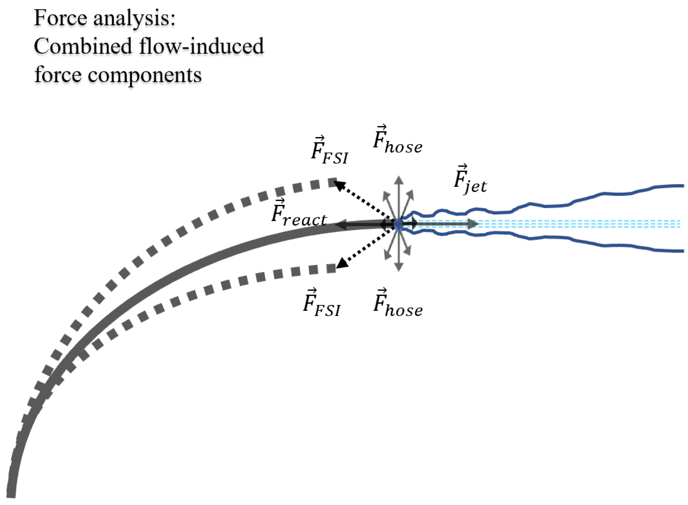
With reference to Figure 6, the net resultant force is the vectorial sum of F h o s e and F r e a c t (or − F j e t ) from Equations (6) and (9).
F F S I ( t ) = ( F r e a c t ( t ) ) 2 + ( F h o s e ) 2 ,
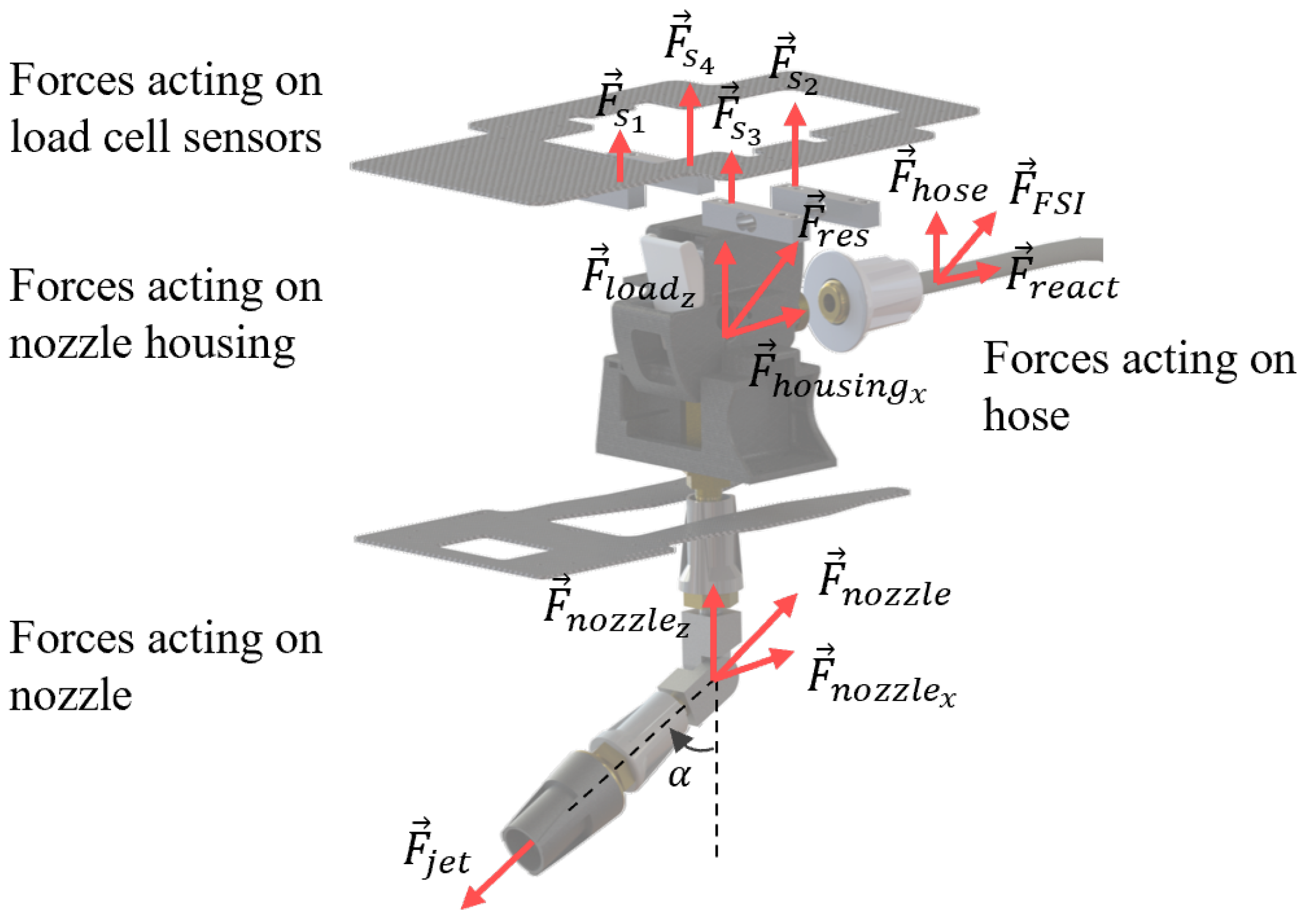
For simplicity, as illustrated in Figure 7, the translated resultant force acting on the UAV platform will be termed as the net flow-induced resultant force F r e s at the nozzle housing and is given by:
F r e s = ( F h o u s i n g x ) 2 + ( F l o a d z ) 2 ,
where F h o u s i n g x = F n o z z l e x + F r e a c t ( t ) t & F l o a d z = F n o z z l e z + F h o s e ( t ) t .

3. UAV Control System, Disturbance, and Feedforward (FF) Strategy

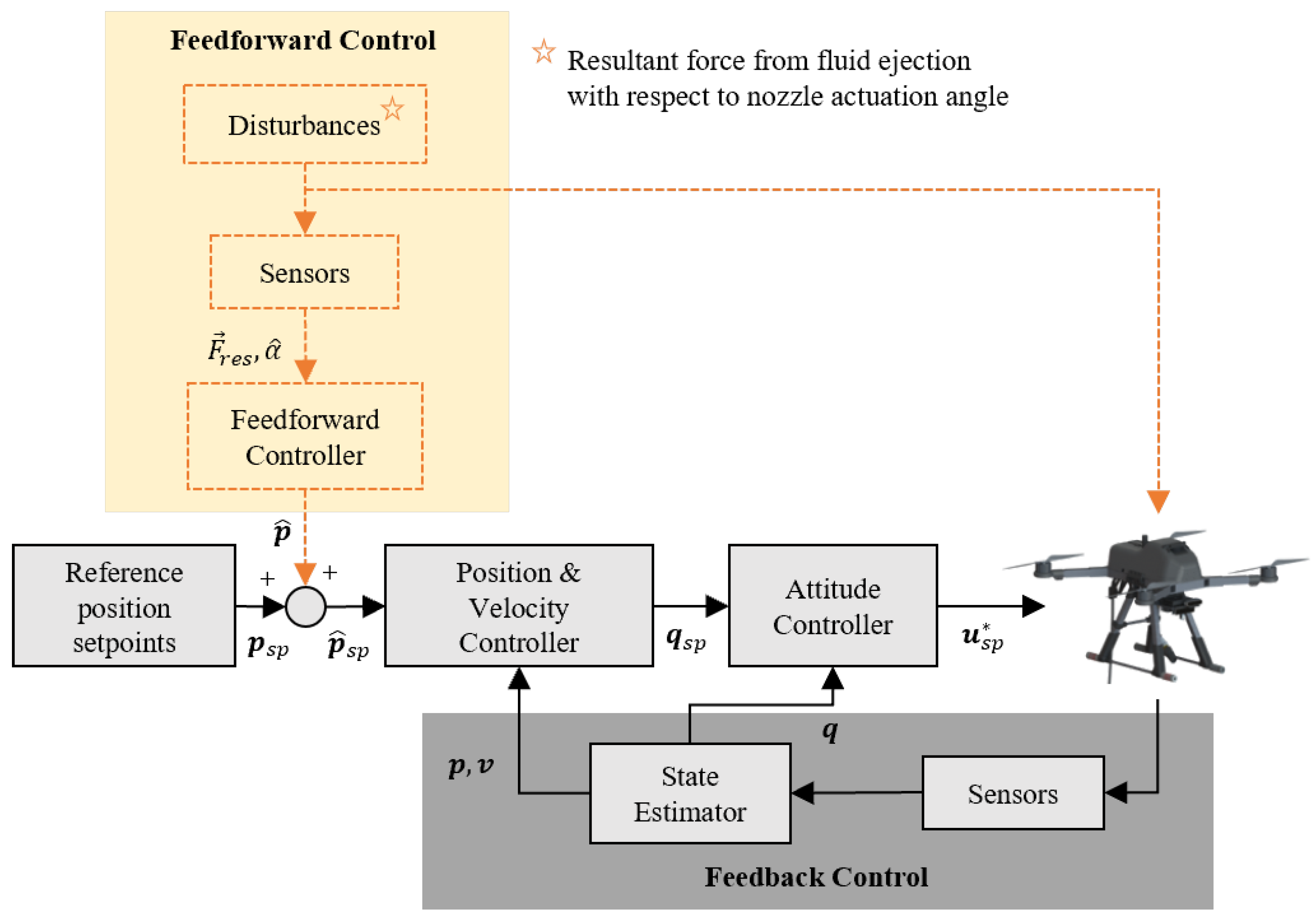
During the ejection process, the UAV will be subjected to unwanted physical disturbances that influence the UAV’s desired position, which may cause instability or potential collision with nearby structures. To reduce such disturbances due to the fluid ejection, an FF-FB strategy is proposed. With reference to Figure 8, the control scheme is comprised of two main loops, namely feedforward (FF) and feedback (FB). Our strategy introduces an FF loop (as highlighted in Figure 8) to a standard FB loop for active UAV position compensation. This section describes a combined FF-FB UAV control scheme with the F r e s as a disturbance input that results in the displacement in UAV position. The FF loop detects the forces caused by the fluid ejection as disturbance input and outputs the estimated corrections for the reference position setpoints, where the FB loop corrects the error between the observed UAV position and the reference position setpoints. This ensures that the UAV is kept as close as possible to the desired setpoints, especially during fluid ejection. The FF loop is comprised of sensors to quantify the disturbance force caused by the fluid ejection and a controller that addresses the measured disturbance ( F r e s ) with estimated position setpoint corrections. The FB loop is comprised of sensors to measure the pose and position of the UAV to update the state estimations in order to reduce the observed error via error dynamics methods.

3.1. UAV Control System

Table 2 list the various definitions of the variables introduced in the control scheme, as shown in Figure 8. The following assumptions were made with regards to the UAV and its control scheme in this study:
Assumptions list 1 for UAV:
  • The origin of the body-fixed frame, B , is set at the center of gravity (CoG) of the UAV;
  • The UAV is symmetrical and rigid;
  • The moment caused by attaching the flexible hose to the UAV is negligible;
  • The dynamics of the UAV motors and propellers are negligible;
  • The thrust and drag forces are proportional to the square of the rotor speed;
  • The flow-induced forces acting on the nozzle housing act in the region of the CoG, and hence any moments generated are negligible;
  • The nozzle is bounded by a single rotary mechanism that limits the fluid jet between the x-z axes only.
Assumptions list 2 for control scheme:
  • The position p and velocity v signals are available;
  • All velocities v and the forces F are bounded;
  • The Euler angles ( ρ , θ , ψ ) satisfy θ π / 2 , and ϕ , ψ π .
In this paper, the UAV dynamic model is assumed to be a standard x quadrotor configuration, with consideration of the above assumptions. Hence, the various controllers and the plant will correspond to the various position-attitude controllers and quadrotor dynamic model, respectively. Proportional-integral-derivative (PID) FB control is employed within the various control loops. Since the UAV will be subjected to a disturbance, resulting in the drift in UAV position due to the fluid ejection, an FF control strategy can be employed in anticipation of the occurrence of the disturbance to minimise the position drift during ejection.
The fluid-ejecting quadrotor dynamics configuration is formulated and structured in a state space representation similar to [25]:
x ˙ = f ( x , u , d ) = A · x + B · u + D · d ,
where A is the system matrix, x is the state vector, B is the input matrix, u is the vector, D is the disturbance matrix, and d is the disturbance vector.
Considering the platform’s moments of inertia and a simple PID FB control loop, the UAV response is stable for any given 3D target position. Noting that the typical UAV state space system does not facilitate onboard fluid ejection, in order to simulate the fluid ejection response on the UAV, the addition of the disturbance matrix is introduced. Refer to Appendix A for the breakdown of the respective matrices.

3.2. Disturbance: Flow-Induced Forces

In this section, the disturbance matrix that describes the relationship between α and F r e s , which acts on the nozzle housing, is investigated and modelled. At the discharge segment, the disturbance model also determines the physical shift in UAV position during ejection for the respective α values. Noting that the change in α value affects the resultant vector direction between F h o u s i n g x and F l o a d z , with reference to Equation (13) and Figure 7, the following assumptions are made for F r e s :
F r e s { F h o u s i n g x , F l o a d z = w j F j e t = 0 α = 0 ° ( w n o z z F n o z z l e c ( 90 ° α ) ) 2 + ( F l o a d z ) 2 0 ° < α < 90 ° F h o u s i n g x = w j F j e t , F l o a d z = 0 α = 90 ° ,
where c represents cos, and w j and w n o z z represent the weights for F j e t and F n o z z l e , respectively, due to some damping effect or material compressibility (which are not studied). Equation (15) presents a large number of possible permutations for the gains w j and w n ; however, one solution is to obtain the F r e s values empirically through a series of UAV flights with ejection for α ( 0 ° ) . With reference to Assumption 1.6 and Appendix A, the disturbance vector becomes: d = [ F h o u s i n g x 0 F l o a d z ≈ 0 0 ≈ 0] T .

3.3. Feedforward (FF) Control Strategy

The presence of the disturbance input caused by the fluid ejection can be minimised with the employment of an FF control loop that can correct the UAV’s position error in anticipation. The FF loop helps to reduce the work needed to be done by the the PID FB loop too. The disturbance input will be measured by the onboard load sensors, which measure the translated resultant force caused by the fluid ejection F r e s on the UAV body. The sensors are made up of an array of single-direction load cells, which detects and measures the presence of the translated force (in +z) experienced by the housing that couples the hose to the UAV. As shown in Figure 7, the load sensors are arranged such that the change in nozzle actuation angle α affects the individual cell measurement, which is critical in determining F r e s .
Since the hose is connected to the nozzle housing and the point of ejection happens at the nozzle, which is offset by the articulated joint, the nozzle experiences an instantaneous jet reaction force. This is translated onto the nozzle housing as the flow-induced force F r e s , which gives each load cells the reading that corresponds to the F l o a d z with respect to α . This information will be fed into the disturbance vector d .

4. Simulations

4.1. Fluid Supply: Flow-Induced Dynamic Force

With reference to Section 2.1, the outcome of a range of flow-induced time response forces F h o s e ( t ) from the fluid supply segment is illustrated in this section, which follows the setup shown in Figure 5. The fluid-conveying hose has a silicone rubber exterior, with flexural modulus ( E I ) of 10 Pa, diameter of 0.006 m, thickness (h) of 0.011 m, and length (L) of 4 m, and the discharge segment of the hose is lifted up to a height (H) of 2 m.
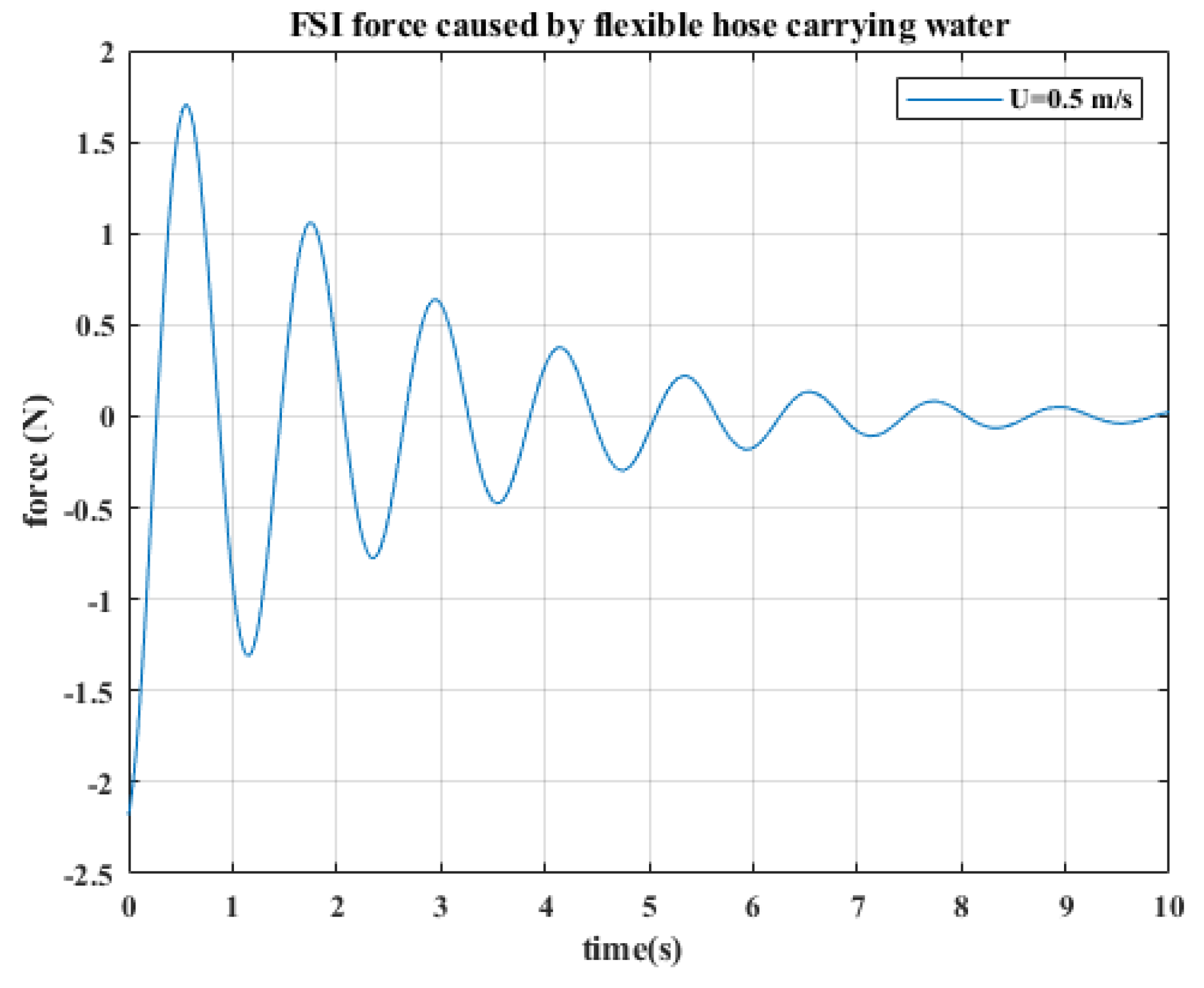
From the current setup shown in Table 1, the pipe inflow velocity (U) is recorded to be 0.54 m/s. The corresponding natural frequencies can be interpolated as shown in Table 3. The corresponding FSI force F h o s e at U = 0.5 m/s is shown in Figure 9. This shows the initial peak magnitude of F h o s e is around 7 N, and it decays to a negligible value (i.e., less than 1 N) within the first few seconds (t >= 5 s).
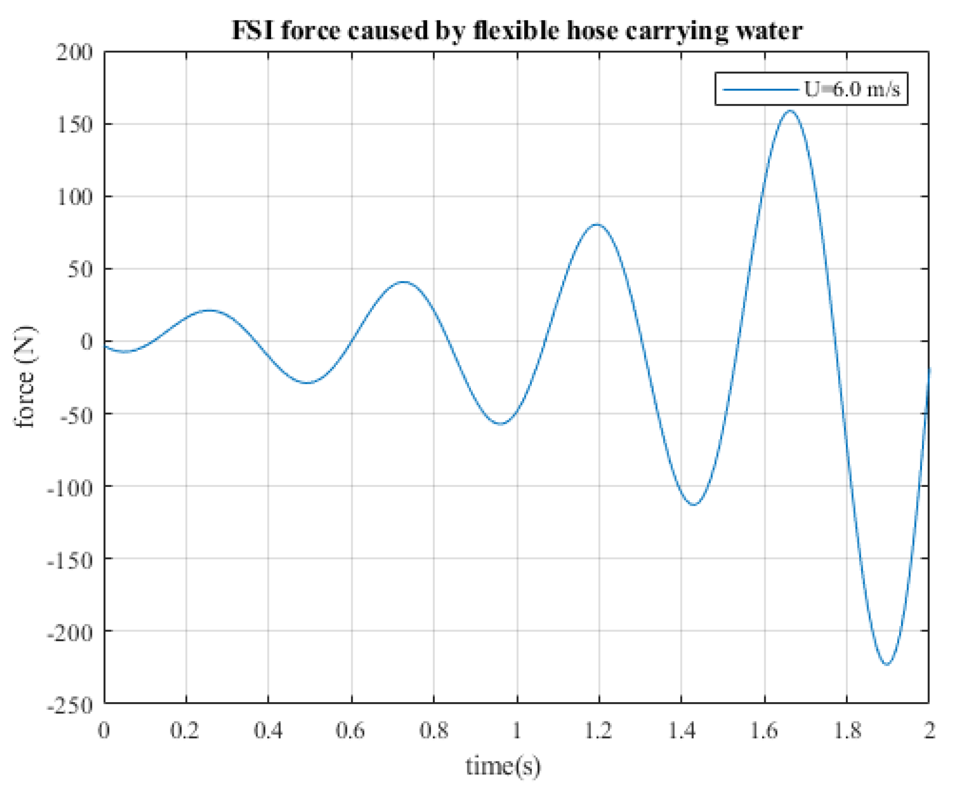
According to Table 3, F h o s e converges for U < 6 m/s and becomes divergent at U 6 m/s. If the fluid velocity reaches the critical value ( U c r i t 6 m/s), the natural frequency variable in Equation (9) will be negative, causing w ( x , T ) to grow exponentially with time and become unstable. Figure 10 shows the divergent behaviour for the simulation when U = 6 m/s. Figure 11 shows the simulation plots of F h o s e against a range of fluid velocities ( U 0.1 4.0 , 6.0 m/s) flowing through the conveying hose. Note that, in these plots, F h o s e are normalised by the dynamic pressure ( 1 2 ρ U 2 ) so as to put them into common scale. For the range of U from 0.1 m/s to 4.0 m/s, the decrease in the normalised FSI force becomes steeper as the velocity increases. At U = 6.0 m/s, the normalised FSI force exhibits an exponential behaviour, with the normalised force reaching O(×10 3 ) (N/m 2 ) and diverging over time.
Figure 12 shows a sequence photo of the colour dye injection test at each instance in order to measure the flow velocity. Colour dye was used under the assumption of it being the perfect tracer for this experiment. Because the injection quantity and the relative velocity (in practice) between the colour tracer and the fluid flow are small, there is a low finite slip velocity between the tracer and flow particles [26]. The setup is comprised of a static rig that holds onto the end of the hose, with an orifice of 7 mm and a 1 m measuring tape fixed at the back of the setup to measure the distance travelled by the stream. The test was recorded with a high frame rate and slowed down to observe the section of the coloured water at each instance, covering a distance of 0.125 m. Instance 1 shows the point where the colouring is first injected into the stream, and the following instances capture the section as it travels downstream. Instance 4 marks the point to stop the timer as, beyond this distance, the fluid jet of initial constant radius was observed to break up into ligaments and droplets due to surface tension and air entrainment, resulting in a decay of jet velocity.
Table 4 shows the measurements of the various sets that were collected, and the flow velocity was averaged at around 0.520 m/s. This information is key to solving Equations (2), (9)–(11).
As illustrated in Figure 9, the F h o s e from the fluid supply only appears and affects the UAV at the initial ejection phase for a few seconds. For U = 0.5 m/s, the peak magnitude is about 7 N, and this force dissipates to a negligible magnitude (<1 N) after a few seconds (t > 5 s). Noting that the natural frequency ω of the exponential term in Equation (9) is positive, the displacement response will decay with time. Hence, this force can be ignored at the fluid supply segment, while focusing only on the force at the discharge segment, as described in Section 3.2.

4.2. Fluid Discharge: UAV Displacement upon Fluid Ejection

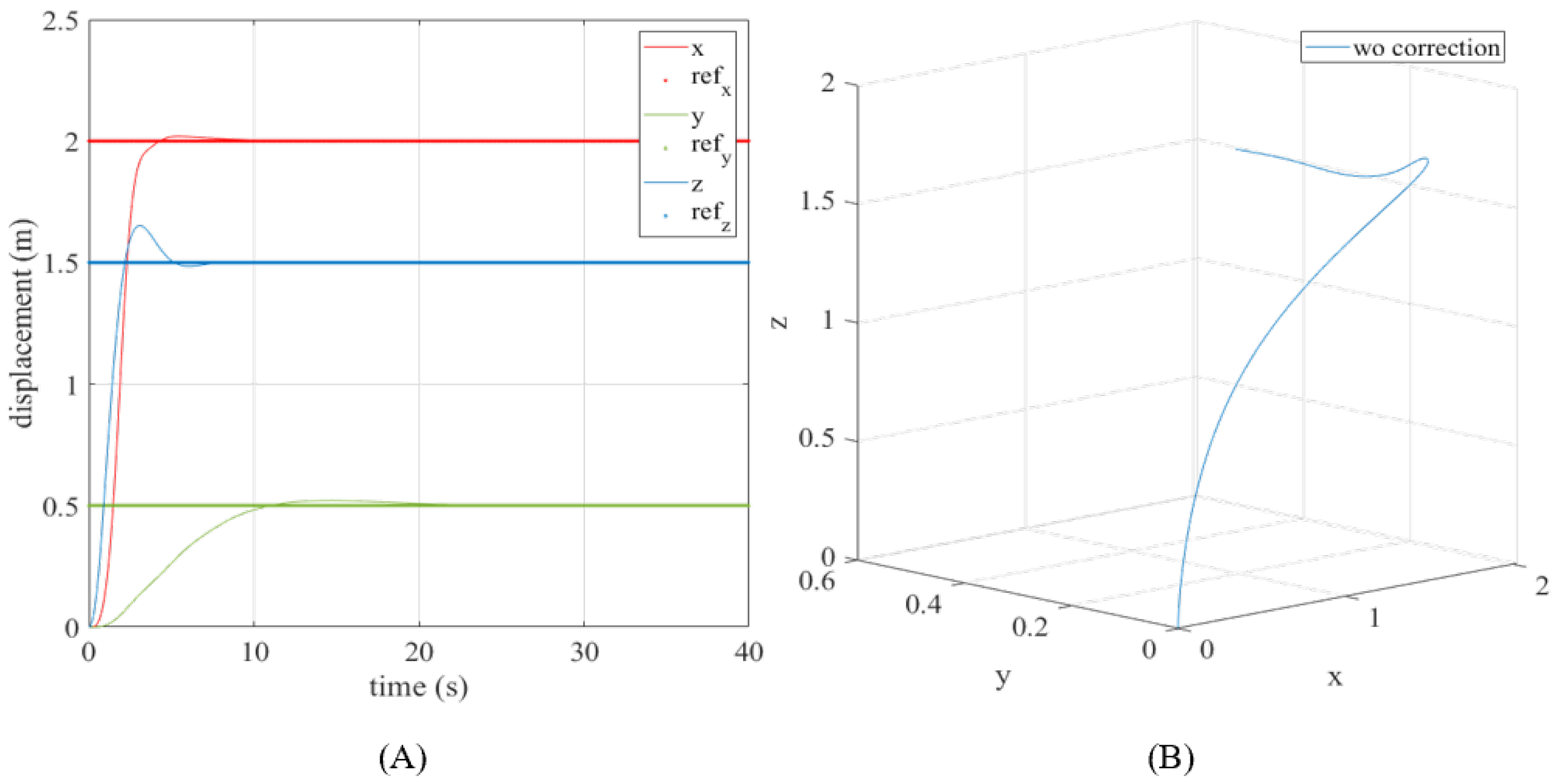
With reference to Section 3.1, the system dynamics in Equation (15) are first simulated with a standard FB control law for a desired (reference) position to observe the UAV response without ejection. Further simulations were conducted to visualise the potential effects of the flow-induced forces acting on the UAV during fluid ejection. Considering the moments of inertia of the actual quadrotor, the simulation shows the UAV response for a desired setpoint (i.e., p = (2.5, 0.5, 1.5) m), as illustrated in Figure 13. The simulation results confirms that the system dynamics were able track the UAV position well, with and without fluid ejection.
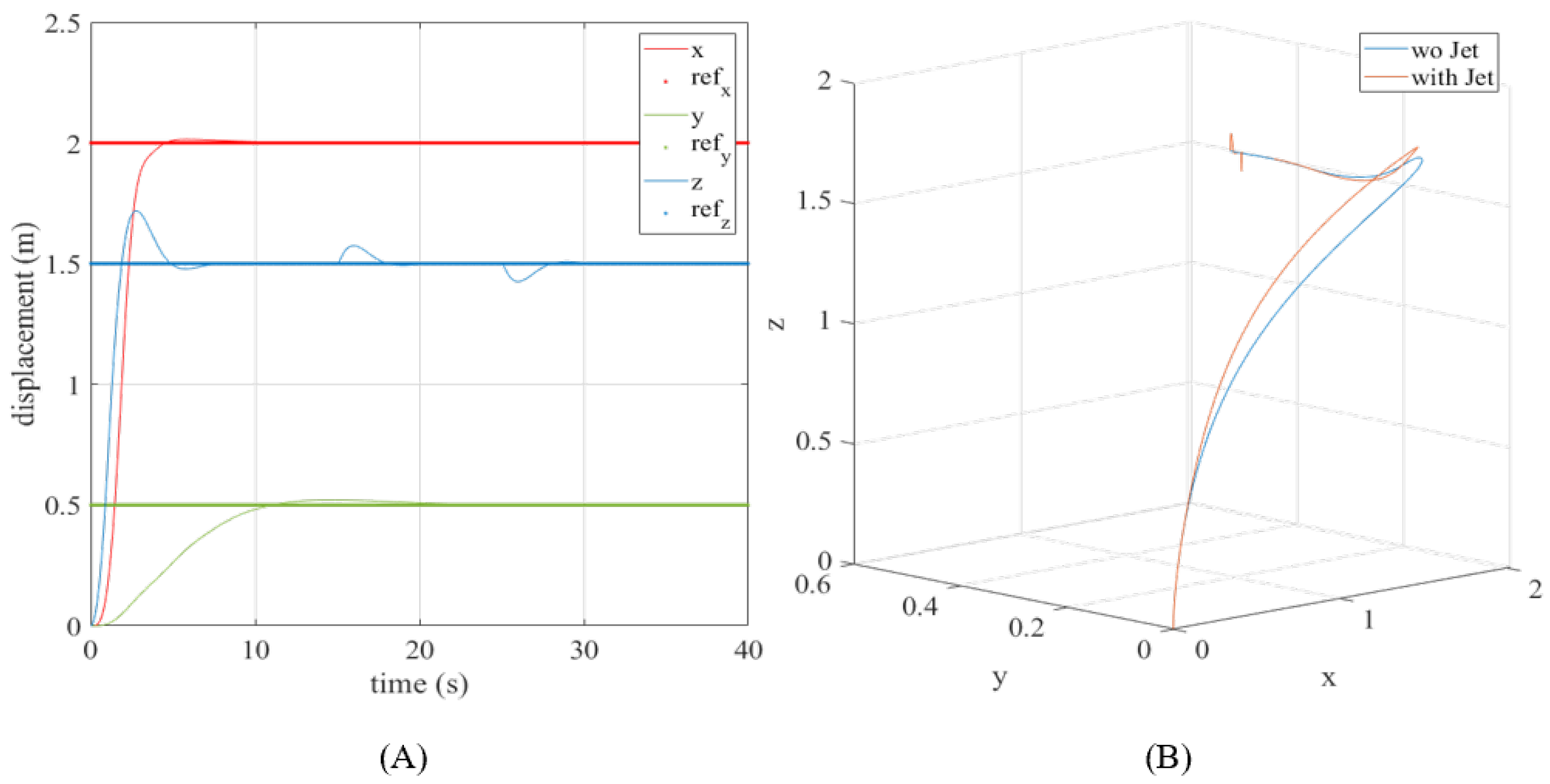
The system becomes slightly more complex when the additional ejection terms are introduced into the system dynamics, especially with increasing α . At this stage, the occurrence of ejection is position-dependent, which means that the UAV should arrive at its desired position before the fluid ejection commences. As illustrated in Figure 14, the fluid ejection results in a physical disturbance to the system, causing the UAV to drift away from its desired position, which will be corrected by the PID FB loop over time. With reference to Equations (9), (11), and (13), Section 4.1 solves for the disturbance vector d, which will be used in this section. The estimated UAV position shift can be determined via simulations with the parameters listed in Appendix B.

4.3. FF-FB Control Scheme

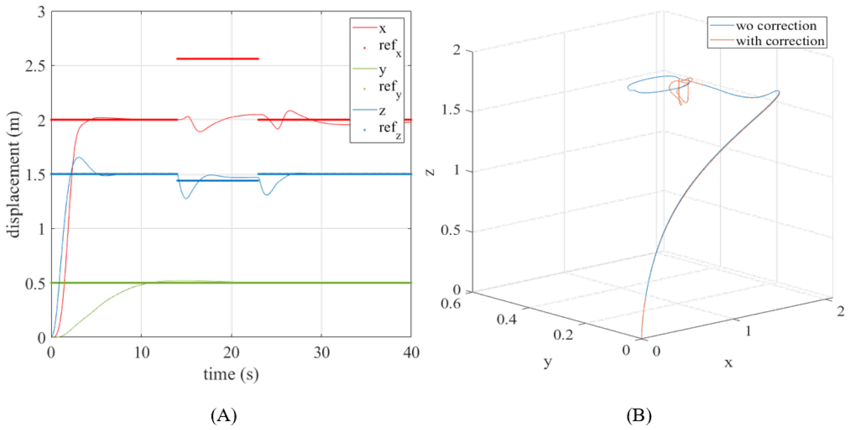
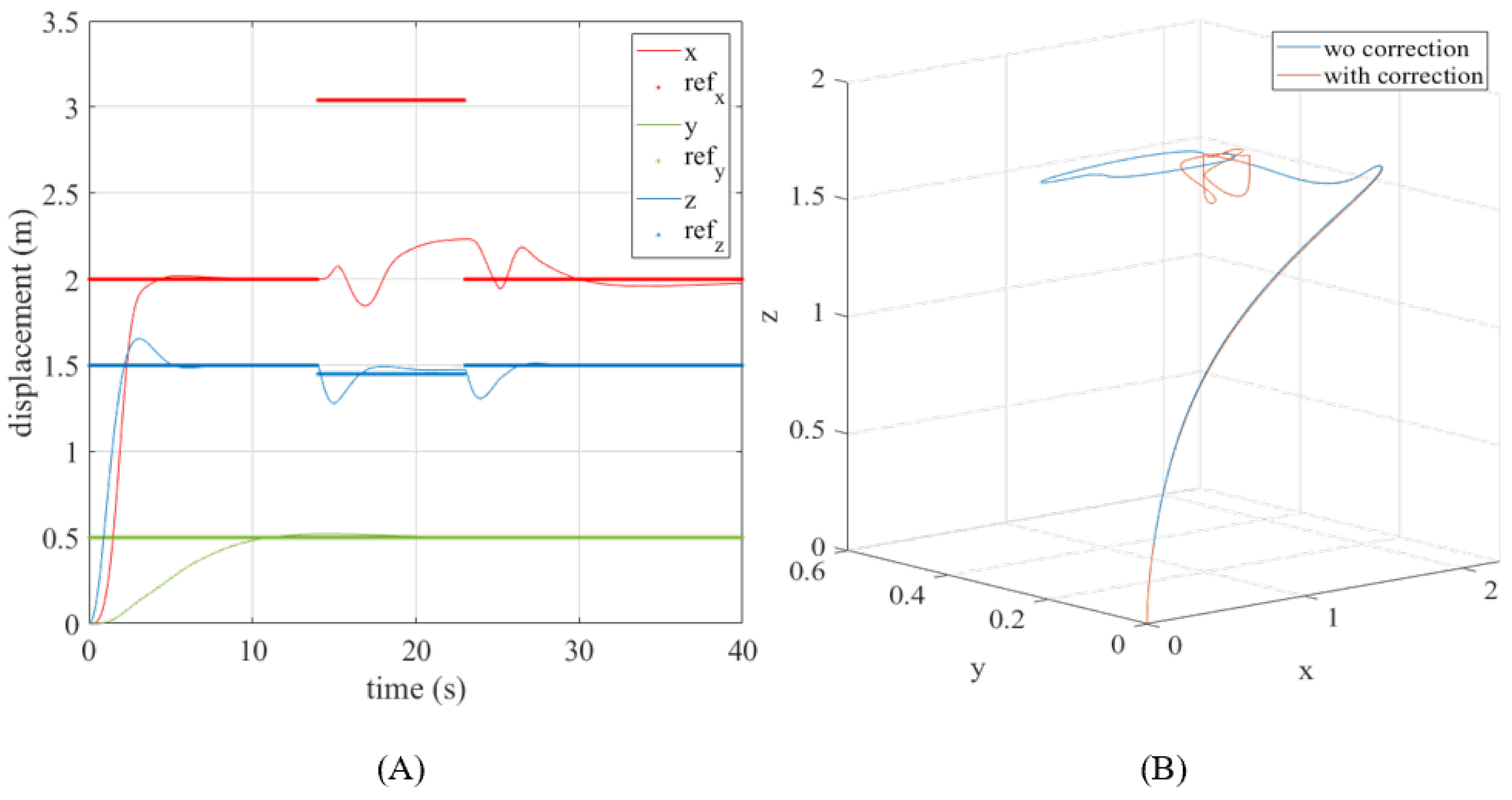
This section shows the simulation results of the UAV position with the employment of the proposed FF-FB control scheme, as described in Section 3.1. The proposed strategy alters the reference position setpoints when fluid ejection occurs. Through these simulations, we were also able to observe the UAV responses with a combined FF-FB control and a standalone FB control, which allows us to be well informed of any potential instability prior to the actual flight experiments. With prior knowledge of the disturbances from the simulation results in Section 4.2, the estimated corrections were made to the initial position setpoints to ensure that the UAV keeps close to its reference setpoints as much as possible during jetting. Figure 15, Figure 16, Figure 17 and Figure 18 illustrate the simulation results for p = (2, 0.5, 1.5) m. From the range of actuation angles, α = 0, 20, 40, and 60 are selected and presented in this section and thereafter.

5. Experimental Validations

5.1. Static Test: Measurements at the Free End of the Hose

In this section, a static test is conducted to investigate and measure the accelerations (or vibrations) at the free end of the hose at different altitudes. According to Figure 19, the setup requires the use of tripod stands to prop the hose up to various altitudes. At the end of the tripods, the hose supports suspend the rear hose and the free end with flexible bands to allow for free movement. An accelerometer attached to the free end measures the accelerations once the pump system is turned on. Suspending the rear hose allows the free end to maintain its orientation at the various altitudes such that the accelerometer captures the accelerations in the respective axes accurately. The accelerometer data are recorded for altitudes of 1 m and 3 m in Figure 20. It can be observed that the accelerations in the respective axes at the free end decay slightly with increasing altitudes. This could be due to the minute pressure drop experienced by the fluid flow at the free end due to the change in altitude, hence causing the fluid to lose some of its energy as it is conveyed through the hose. Noting that the mass of the free end (including the rear hose and the water being conveyed through it) is approximately 0.33 kg, and the average peak accelerations in the z-axis measure approximately 5–6 m/s 2 , we found that this translates to a peak force of about 1.5 N. This validates our simulation findings for F h o s e ( t ) with the stated flow velocity (U = 0.52 m/s), as shown in Figure 9.

5.2. UAV Response to Fluid Ejection with Feedback (FB) Control Loop Only

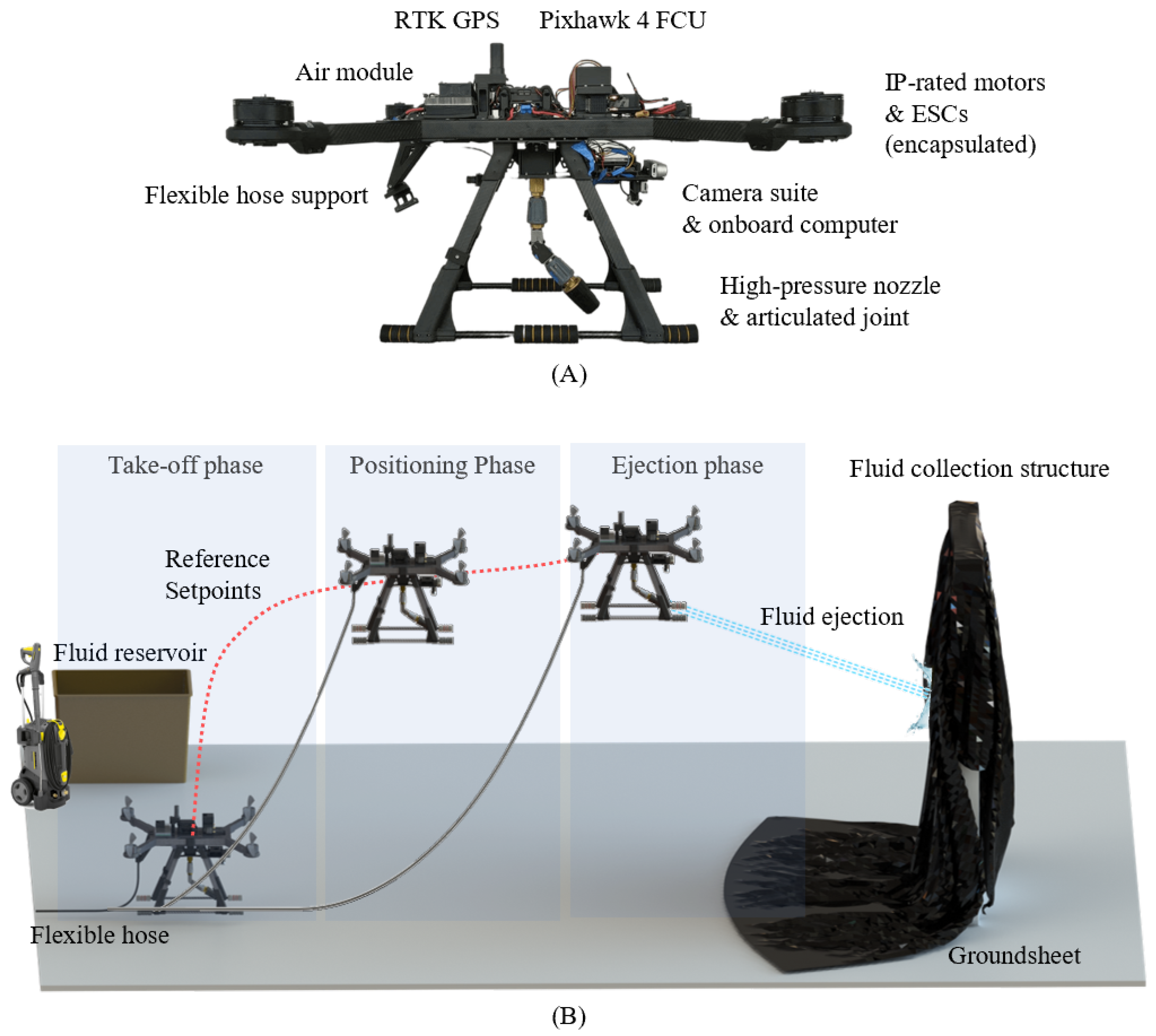
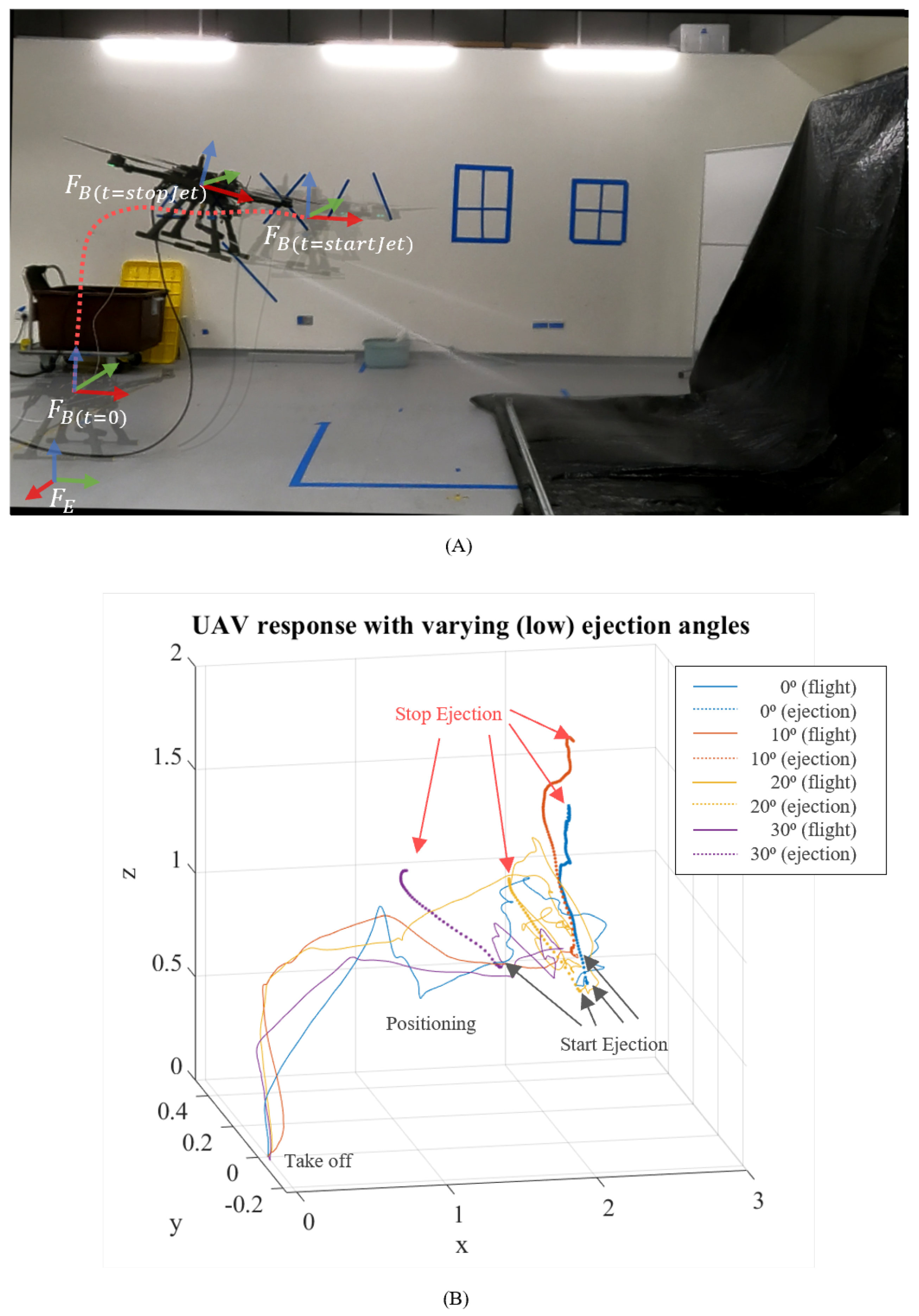
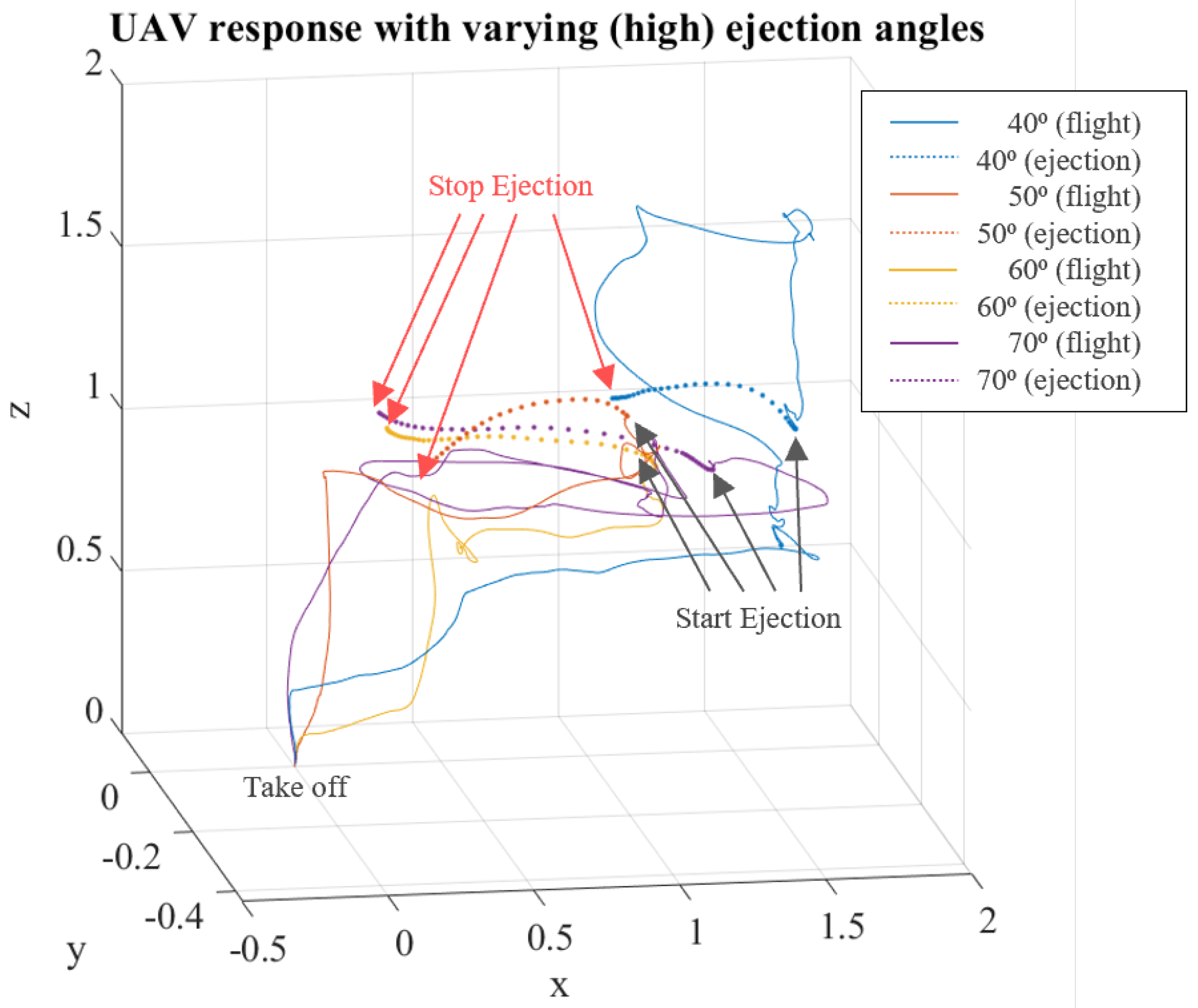
In this experiment, we deploy a customised fluid-ejection-capable quadrotor UAV, with the parameters listed in Appendix C, for data collection. To understand how the FF control loop can benefit the system, we measure the disturbance on the UAV with a standard FB control strategy throughout its entire flight. The disturbance experienced by the UAV can be studied by conducting flight tests in an optitrack environment to quantify the UAV response (in x , y , z ) during fluid ejection. As illustrated in Figure 21, a dynamic test is conducted with the free end of the hose attached to the UAV to observe the flow-induced forces in practice. In this experiment, the UAV takes off, and then moves to and hovers at a desired position in three different phases. In its ejection phase, the pump system is turned on for fluid ejection, which translates the flow-induced effects onto the UAV. At this stage, the UAV is allowed to react naturally to the F r e s with little to no human intervention, unless it exits the flying area or if an unstable flight is imminent. The respective reactions experienced by the UAV are recorded and illustrated in Figure 22 and Figure 23, where the UAV’s response from the take-off phase to the ejection phase is shown. The more data points are logged in a particular instance, the longer the UAV is hovering at that position.
The black arrows depict the start of the onboard ejection, and the red depicts the end of the ejection. The respective paths between each black and red arrow show the UAV response when subjected to the resultant force F r e s caused by the reaction and FSI forces, as shown in Table 5. It can be seen that with lower ejection angles (≤30°), the F r e s has a larger vertical (upward) component, while higher ejection angles have a larger lateral (backward) component acting on the UAV. With the information in Table 5, we can guide the formulation of the FF controller with better precision in the next section.

5.3. UAV Response to Fluid Ejection with Proposed Strategy

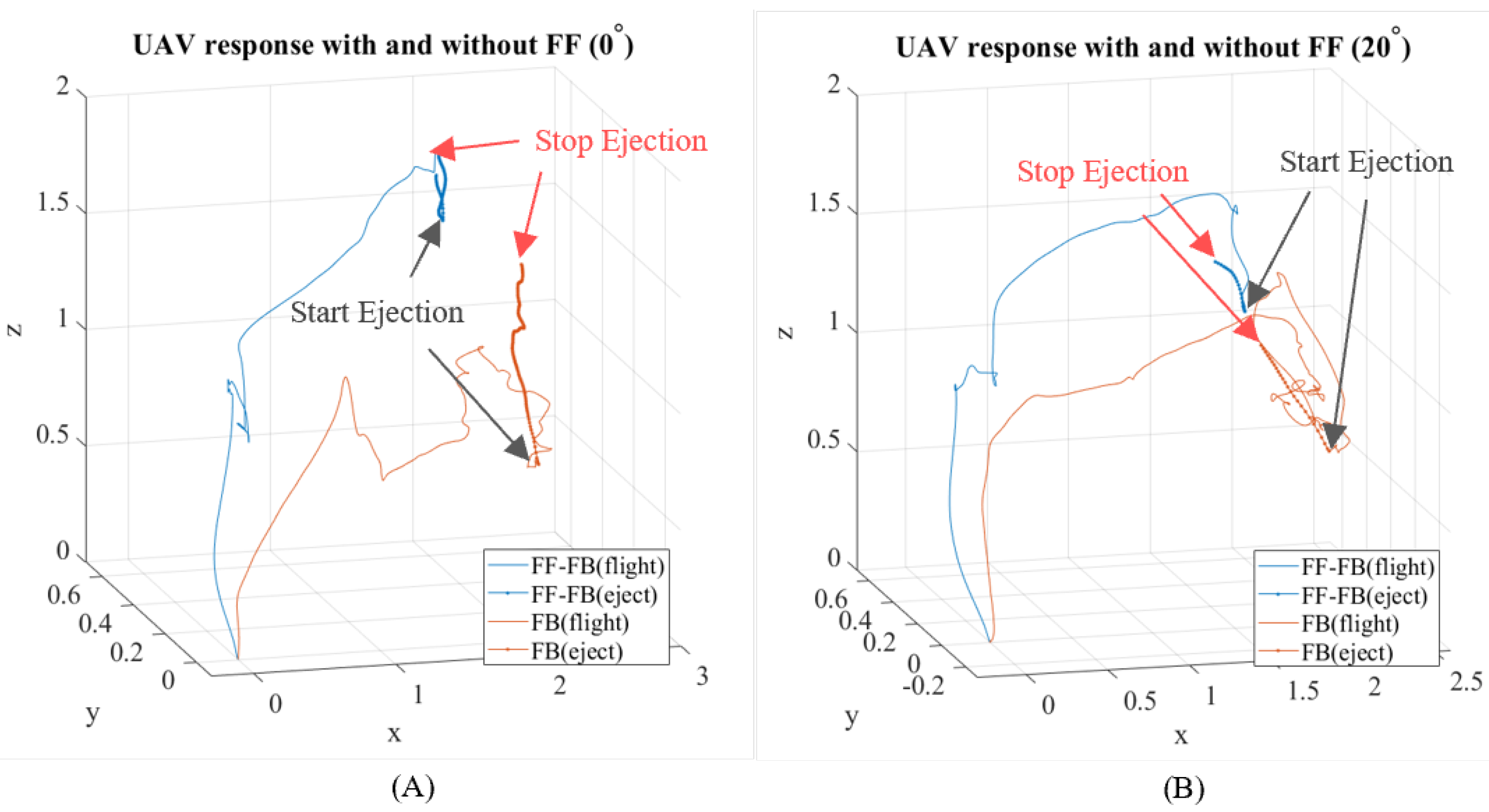
In this section, we present the findings of our proposed strategy with the knowledge acquired from the previous chapters. The experiment will test the FF-FB control in practice and measure the overall position shift during ejection. The setup will be similar to Figure 21, and we compare the UAV response during the ejection phase with that in Section 5.2. Figure 24 and Figure 25 visualise the UAV responses for the FF-FB and FB control strategy at their respective α angles. Table 6 states the various initial and final positions of the UAV during its ejection phase. However, identifying just the difference does not ensure that the UAV is close to the reference setpoint during ejection. Hence, we present the root mean square error (RMSE) for the x and z axes in Table 7 (note Assumption 1.7 in Section 3.1). The RMSE(x) and RMSE(z) show that the inclusion of an FF controller in the control system drastically improved the UAV system during the ejection phase, especially for the axis with a larger difference in its respective α (i.e., x-axis for higher α or z-axis for lower α ). In Table 7, we present the RMSE values for both FF-FB and FB control strategies and the percentage improvement for the respective axes and actuation angles. We observed that for RMSE(z) for α = 40°, the FB control worked better. This could be due to tuning or time synchronisation issues, which could mean a possible time lag between the detection of disturbance and the reaction. That being said, the reduction is small and can be easily fine-tuned for a better response. From the experiments, our proposed strategy shows an average improvement of 61.14% in the x-axis and 22.46% in the z-axis.
We have provided supplementary material in the form of a video that showcases the respective live experiments that we have conducted for this paper. The video features experimental procedures and validations with regards to the static fluid-related tests and live UAV flight (with fluid ejection) tests as described in this paper. More information on the video can be found under Supplementary Materials in Section 6.

6. Conclusions and Future Work

The work presented in this article shows a full implementation of a combined FF-FB control scheme for a fluid-ejecting UAV, from modelling of the fluid–structure interaction (FSI) between the flexible hose carrying fluid and the connected UAV to the formulation of the proposed control strategy through simulations and experiments. The FSI consists of the oscillatory force from the fluid supply segment and the reactive jet force from the fluid discharge segment. There is a critical flow velocity from the fluid supply segment, governed by its natural frequencies, in which the oscillation will diverge exponentially if it exceeds this limit. The combined FSI effect results in a disturbance force acting on the UAV. The proposed FF-FB control scheme is designed to mitigate such effects. The UAV system offers an alternative to eliminate risk exposure during high-rise maintenance (cleaning). Our work is directed to be UAV and pump agnostic. The proposed strategy makes high-pressure fluid ejection from a hovering UAV more stable, which may encourage higher adoption of such a cleaning system for more industrial sectors. Although we obtained promising results, we also recognise certain limitations that it might bear, such as time synchronisation, which refers to the time difference in sensing and UAV compensation. Hence, with the analytical flow-induced model that we obtained from this paper, our future work will look towards implementing more complex, intuitive model-based or learning-based control strategies to improve the dynamic stability and robustness of such fluid-ejecting UAV systems.

Supplementary Materials

Supplementary material includes a video describing the proposed work and features the live experimental procedures and validations that were conducted to verify our models. The video can be found via this link: https://youtu.be/VJ2553yNHQs (accessed on 1 February 2022).

Author Contributions

Conceptualization, S.M.L., W.H.N., S.S., S.K.W. and S.F.; methodology, S.M.L., W.H.N., S.S., S.K.W. and S.F.; software, S.M.L., W.H.N., S.S., and S.K.W.; validation, S.M.L., W.H.N., S.S., S.K.W. and J.L.; formal analysis, S.M.L., W.H.N., S.S., S.K.W. and J.L.; investigation, S.M.L., W.H.N., S.S., S.K.W. and S.F.; resources, S.S. and S.F.; data curation, S.M.L., W.H.N., S.S., S.K.W. and J.L.; writing—original draft preparation, S.M.L., S.S. and S.F.; writing—review and editing, S.M.L., W.H.N. and S.S.; visualization, S.M.L., W.H.N., S.S. and J.L.; supervision, S.S. and S.F.; project administration, S.S. and S.F.; funding acquisition, S.F. All authors have read and agreed to the published version of the manuscript.

Funding

This work is funded by the National Robotics R&D Programme Office and Agency for Science, Technology and Research: W1925d0056.

Institutional Review Board Statement

Not applicable.

Informed Consent Statement

Not applicable.

Data Availability Statement

Not applicable.

Acknowledgments

Research supported by the National Robotics R&D Programme Office and Agency for Science, Technology and Research (A*STAR) under its National Robotics Programme - Robotics Enabling Capabilities and Technologies (W1925d0056).

Conflicts of Interest

The authors declare no conflict of interest.

Abbreviations

The following abbreviations are used in this manuscript:
FFFeedforward
FBDFeedback
FSIFluid structure interaction
PIDProportional-Integral-Derivative
CoGCenter of gravity
UAVUnmanned aerial vehicle
COTSCommercial-off-the-shelf
MEWPMechanised elevated work platforms

Appendix A

x ˙ = x ˙ y ˙ z ˙ ϕ ˙ θ ˙ ψ ˙ x ¨ y ¨ z ¨ ϕ ¨ θ ¨ ψ ¨ T ,
A = 0 0 0 0 0 0 1 0 0 0 0 0 0 0 0 0 0 0 0 1 0 0 0 0 0 0 0 0 0 0 0 0 1 0 0 0 0 0 0 0 0 0 0 0 0 1 a 1 a 2 0 0 0 0 0 0 0 0 0 0 a 3 a 4 0 0 0 0 0 0 0 0 0 0 a 5 a 6 0 0 0 0 0 0 a 7 0 0 0 0 0 0 0 0 0 0 0 0 a 7 0 0 0 0 0 0 0 0 0 0 0 0 a 8 0 0 0 0 0 0 0 0 0 0 0 0 0 a 9 0 0 0 0 0 0 0 0 0 0 a 10 0 0 0 0 0 0 0 0 0 0 0 a 11 0 0 ,
where (sin = s, cos = c & tan = t), a 1 = s ( ϕ ) t ( θ ) , a 2 = c ( ϕ ) t ( θ ) , a 3 = c ( ϕ ) , a 4 = s ( ϕ ) , a 5 = s ( ϕ ) c ( θ ) , a 6 = c ( ϕ ) c ( θ ) , a 7 = F d r a g , a 8 = ( g + F d r a g ) m , a 9 = ( ( I y y I z z ) ψ ˙ I x x , a 10 = ( ( I z z I x x ) ψ ˙ I y y , a 11 = ( ( I x x I y y ) θ ˙ I z z ,
x = [ x   y   z   ϕ   θ   ψ   x ˙   y ˙   z ˙   ϕ ˙   θ ˙   ψ ˙ ] T ,
B = 0 0 0 0 0 0 0 0 0 0 0 0 0 0 0 0 0 0 0 0 0 0 0 0 b 1 0 0 0 b 2 0 0 0 b 3 0 0 0 0 b 4 0 0 0 0 b 5 0 0 0 0 b 6 ,
b 1 = ( s ( ϕ ) s ( ψ ) c ( ϕ ) s ( θ ) c ( ψ ) ) m , b 2 = ( c ( ϕ ) s ( θ ) s ( ψ ) s ( ϕ ) c ( ψ ) ) m , b 3 = c ( θ ) c ( ψ ) g m , b 4 = 1 I x x , b 5 = 1 I y y , b 6 = 1 I z z ,
u = F T τ ϕ τ θ τ ψ T ,
D = 0 0 0 0 0 0 0 0 0 0 0 0 0 0 0 0 0 0 0 0 0 0 0 0 0 0 0 0 0 0 0 0 0 0 0 0 d 1 0 0 0 0 0 0 0 0 0 0 0 0 0 d 2 0 0 0 0 0 0 d 3 0 0 0 0 0 0 d 4 0 0 0 0 0 0 d 5 ,
where α is the nozzle actuation angle, d 1 = c ( α ) ( c ( ϕ ) s ( θ ) c ( ψ ) + s ( ϕ ) s ( ψ ) ) m , d 2 = c ( α ) ( c ( ϕ ) c ( θ ) ) m , d 3 = 1 I x , d 4 = 1 I y , d 5 = 1 I z ,
d = F e j e c t x F e j e c t y F e j e c t z τ e j e c t x τ e j e c t y τ e j e c t z T ,

Appendix B

Table A1. Parameters used in simulations.
ParametersValue
No. of iterations (n)4000
Sample frequency (hz)100
UAV mass (kg)9.01
Ixx, Iyy, Izz0.466, 0.646, 0.417
F l o a d z (N)17
Inner PID x 1.8, 0.2, 3.4
Inner PID y 2.0, 0.0, 0.5
Inner PID ψ 1.0, 0.0, 0.0
Outer PID θ 0.265, 0.0, 0.29
Outer PID ϕ 0.01, 0.0, 0.045
Outer PID ψ 1.0, 0.0, 0.0
Outer PID t h r u s t 150.0, 150.0, 100

Appendix C

Table A2. Parameters used in experiments.
ParametersValue
Frame configurationQuadrotor-X
Power rating (S)12 (tethered)
UAV mass (kg)9.010
Height (m)0.567
Length, diagonal (m)0.970
Flight controller unitPixhawk 4
Propeller length (m)0.559
Pump pressure (bar)120
Ixx, Iyy, Izz0.466, 0.646, 0.417
Recorded F l o a d z (N)11.77
Inner PID θ 5.000, 0.000, 0.000
Inner PID ϕ 5.000, 0.000, 0.000
Inner PID ψ 2.800, 0.000, 0.000
Outer PID θ 0.110, 0.100, 0.001
Outer PID ϕ 0.100, 0.200, 0.001
Outer PID ψ 0.200, 0.100, 0.000

References

  1. Giles, D.; Billing, R. Deployment and Performance of a UAV for Crop Spraying. Chem. Eng. Trans. 2021, 44, 307–312. [Google Scholar]
  2. Martinez-Guanter, J.; Agüera, P.; Agüera, J.; Pérez-Ruiz, M. Spray and economics assessment of a UAV-based ultra-low-volume application. Precis. Agric. 2020, 21, 226–243. [Google Scholar] [CrossRef]
  3. Lopez Lopez, R.; Batista Sanchez, M.J.; Perez Jimenez, M.; Arrue, B.C.; Ollero, A. Au-tonomous UAV System for Cleaning Insulators in Power Line Inspection and Maintenance. Sensors 2021, 21, 8488. [Google Scholar] [CrossRef] [PubMed]
  4. Uddin, S.M.; Hossain, M.R.; Rabbi, M.S.; Hasan, M.A.; Rahman Zishan, M.S. Unmanned Aerial Vehicle for Cleaning the High Rise Buildings. In Proceedings of the 2019 International Conference on Robotics, Electrical and Signal Processing Techniques (ICREST), Dhaka, Bangladesh, 10–12 January 2019; pp. 657–661. [Google Scholar] [CrossRef]
  5. Sun, Y.; Jing, Z.; Dong, P.; Huang, J.; Chen, W.; Leung, H. A Switchable Unmanned Aerial Manipulator System for Window-Cleaning Robot Installation. IEEE Robot. Autom. Lett. 2021, 6, 3483–3490. [Google Scholar] [CrossRef]
  6. Lee, S.M.; Chien, J.L.; Tang, E.; Lee, D.; Liu, J.; Lim, R.; Foong, S. Hybrid Kinematics Modelling for an Aerial Robot with Visual Controllable Fluid Ejection. In Proceedings of the 2020 IEEE/ASME International Conference on Advanced Intelligent, Boston, MA, USA, 6–9 July 2020; pp. 832–838. [Google Scholar]
  7. Ando, H.; Ambe, Y.; Ishii, A.; Konyo, M.; Tadakuma, K.; Maruyama, S.; Tadokoro, S. Aerial Hose Type Robot by Water Jet for Fire Fighting. IEEE Robot. Autom. Lett. 2018, 3, 1128–1135. [Google Scholar] [CrossRef]
  8. Ando, H.; Ambe, Y.; Yamaguchi, T.; Konyo, M.; Tadakuma, K.; Maruyama, S.; Tadokoro, S. Fire Fighting Tactics with Aerial Hose-type Robot “Dragon Firefighter”. In Proceedings of the 2019 IEEE International Conference on Advanced Robotics and Its Social Impacts (ARSO)2019, Beijing, China, 31 October–2 November 2019; pp. 291–297. [Google Scholar] [CrossRef]
  9. Gaith, M. Flow Induced Vibration of Cantilever Tapered Pipes Transporting Fluid. WSEAS Trans. Fluid Mech. 2021. [Google Scholar] [CrossRef]
  10. Li, B.; Wang, Z.; Jing, L. Dynamic Response of Pipe Conveying Fluid with Lateral Moving Supports. Shock Vib. 2018, 2018, 3295787. [Google Scholar] [CrossRef]
  11. Ibrahim, R. Overview of mechanics of pipes conveying fluids—Part I: Fundamental studies. J. Press. Vessel. Technol. 2010, 132, 521. [Google Scholar] [CrossRef]
  12. Paidoussis, M.P. Fluid-Structure Interactions: Slender Structures and Axial Flow; Academic Press: Cambridge, MA, USA, 1998; Volume 1. [Google Scholar]
  13. Modarres-Sadeghi, Y.; Païdoussis, M.P. Chaotic oscillations of long pipes conveying fluid in the presence of a large end-mass. Comput. Struct. 2013, 122, 192–201. [Google Scholar] [CrossRef]
  14. Paidoussis, M.P.; Issid, N. Dynamic stability of pipes conveying fluid. J. Sound Vib. 1974, 33, 267–294. [Google Scholar] [CrossRef]
  15. Liu, X.; Zhou, H. Unmanned Water-Powered Aerial Vehicles: Theory and Experiments. IEEE Access 2019, 7, 15349–15356. [Google Scholar] [CrossRef]
  16. Miyazaki, R.; Paul, H.; Kominami, T.; Martinez, R.R.; Sumetheeprasit, B.; Shimonomura, K. Development of High-Pressure Washing Aerial Robot Employing Multirotor Platform with Add-on Planar Translational Driving System. In Proceedings of the 2021 Aerial Robotic Systems Physically Interacting with the Environment (AIRPHARO), Biograd na Moru, Croatia, 4–5 October 2021; pp. 1–4. [Google Scholar] [CrossRef]
  17. Viegas, C.; Chehreh, B.; Andrade, J.; Lourenço, J. Tethered UAV with Combined Multi-rotor and Water Jet Propulsion for Forest Fire Fighting. J. Intell. Robot. Syst. 2022, 104, 21. [Google Scholar] [CrossRef]
  18. Gaith, M. The Vibration of Tubular Beam Conveying Fluid with Variable Cross Section. Period. Polytech. Mech. Eng. 2021, 65, 56–62. [Google Scholar] [CrossRef]
  19. Benjamin, T.B. Dynamics of a system of articulated pipes conveying fluid-I. Theory. Pro-ceedings of the Royal Society of London. Ser. A Math. Phys. Sci. 1962, 261, 457–486. [Google Scholar]
  20. Paıdoussis, M.; Li, G. Pipes Conveying Fluid: A Model Dynamical Problem. J. Fluids Struct. 1993, 7, 137–204. [Google Scholar] [CrossRef]
  21. Meng, D.; Guo, H.Y.; Xu, S.P. Non-linear dynamic model of a fluid-conveying pipe undergo-ing overall motions. Appl. Math. Model. 2011, 35, 781–796. [Google Scholar] [CrossRef]
  22. Gregory, R.; Paidoussis, M. Unstable oscillation of tubular cantilevers conveying fluid II. Experiments. In Proceedings of the Royal Society of London. Ser. A Math. Phys. Sci. 1966, 293, 528–542. [Google Scholar]
  23. Liu, H.; Wang, J.; Kelson, N.; Brown, R.J. A study of abrasive waterjet characteristics by CFD534 simulation. J. Mater. Process. Technol. 2004, 153, 488–493. [Google Scholar] [CrossRef] [Green Version]
  24. Urazmetov, O.; Cadet, M.; Teutsch, R.; Antonyuk, S. Investigation of the flow phenomena in high-pressure water jet nozzles. Chem. Eng. Res. Des. 2021, 165, 320–332. [Google Scholar] [CrossRef]
  25. Sabatino, F.D. Quadrotor Control: Modeling, Nonlinearcontrol Design, and Simulation. Master’s Thesis, KTH Electrical Engineering, Stockholm, Sweden, 2015. [Google Scholar]
  26. Johnson, R. Handbook of Fluid Dynamics; CRC Press: Boca Raton, FL, USA, 2016. [Google Scholar]
Figure 1. (A) Sheltered walkway manual structural cleaning. (B) Cargo hold manual cleaning. Image credits: https://mfame.guru/cargo-hold-cleaning/ (accessed on: 25 February 2022).
Drones 06 00088 g001
Figure 2. (A) Fluid–structure interactions on a UAV. (B) Safety awareness and manpower requirements for MEWP and UAV solutions.
Drones 06 00088 g002
Figure 3. Effect of fluid forces on UAV from supply and discharge segments.
Drones 06 00088 g003
Figure 4. Schematic diagram of the water supply segment. Note: * refers to nozzle housing, which is situated where F r x n 1 originates (in Figure 3); it is also the point of connection between the hose and the UAV.
Drones 06 00088 g004
Figure 5. (A) FSI components free-body schematic: cantilevered hose ejecting fluid from a suspended free end. (B) Flow components free-body schematic: schematic diagram at the discharge segment for a range of jetting force between 0° and 90°.
Drones 06 00088 g005
Figure 6. Combined flow-induced force components for free-body schematic from Figure 5A,B.
Drones 06 00088 g006
Figure 7. Exploded view: forces acting on individual frames of the onboard nozzle housing.
Drones 06 00088 g007
Figure 8. Combined FF-FB control scheme. The highlighted segment is the proposed FF control loop that will update the UAV control system on external forces caused by onboard fluid ejection. The desired position setpoints are summed with the output from the FF controller to produce the updated desired setpoints. The outer loop governs position control, and the inner loop governs attitude control. * Rotor speed (u* = [u1, u2, u3, u4]).
Drones 06 00088 g008
Figure 9. Time response of F h o s e from fluid supply segment at U = 0.5 m/s (actual setting on proposed UAV system).
Drones 06 00088 g009
Figure 10. Time response of F h o s e from fluid supply side at U c r i t = 6 m/s (critical speed, theoretical response prediction).
Drones 06 00088 g010
Figure 11. Time response of normalised F h o s e over a range of fluid velocities ( U 0.1 4.0 , 6.0 m/s) flowing through the conveying hose.
Drones 06 00088 g011
Figure 12. Flow velocity test: colour dye injection to study the velocity of the fluid flow from the free end of the conveying hose.
Drones 06 00088 g012
Figure 13. Standard UAV response to desired input with FB control only, with no fluid ejection: (A) UAV time response to respective desired inputs, (B) UAV 3D position.
Drones 06 00088 g013
Figure 14. Standard UAV response to desired input with FB control only, with and without 0° fluid ejection: (A) UAV time response to respective desired inputs, (B) UAV 3D position.
Drones 06 00088 g014
Figure 15. UAV FF-FB response comparison during 0° fluid ejection with and without active compensation: (A) UAV time response with corrections, (B) 3D UAV positions with and without corrections.
Drones 06 00088 g015
Figure 16. UAV response comparison during 20° fluid ejection with and without active compensation: (A) UAV time response with corrections, (B) 3D UAV positions with and without corrections.
Drones 06 00088 g016
Figure 17. UAV response comparison during 40° fluid ejection with and without active compensation: (A) UAV time response with corrections, (B) 3D UAV positions with and without corrections.
Drones 06 00088 g017
Figure 18. UAV response comparison during 60° fluid ejection with and without active compensation: (A) UAV time response with corrections, (B) 3D UAV positions with and without corrections.
Drones 06 00088 g018
Figure 19. Static rig setup: acceleration (vibration) test on free end of the flexible hose.
Drones 06 00088 g019
Figure 20. Accelerometer data for the experiment defined in Section 5.1: (A) free end at altitude = 1 m, (B) free end at altitude = 3 m.
Drones 06 00088 g020
Figure 21. (A) UAV hardware setup used for the experiments in this paper. (B) Experimental setup with three different phases: take-off, positioning, and ejection.
Drones 06 00088 g021
Figure 22. (A) Actual UAV response to 70° fluid ejection. (B) UAV response (optitrack) to low ejection angles.
Drones 06 00088 g022
Figure 23. UAV response (optitrack) to high ejection angles.
Drones 06 00088 g023
Figure 24. UAV response (optitrack) for FF-FB vs. FB: (A) α = 0°, (B) α = 20°.
Drones 06 00088 g024
Figure 25. UAV response (optitrack) for FF-FB vs. FB: (A) α = 40°, (B) α = 60°.
Drones 06 00088 g025
Table 1. Setup parameters and values.
ParametersValues
Pump pressure system120 bar (12 MPa)
(jet pressure), P j e t
Jet exit velocity (at nozzle), v j e t 154.94 m/s, calculated
Pipe inflow velocity (before nozzle), v i n f l o w 0.54 m/s, measured
Jet force, F j e t 18.77 N
Table 2. UAV variables and parameters.
VariablesDefinitions
p Position vector in ε
q Quaternion vector in ε
u * Rotor speed (u* = [ u 1 , u 2 , u 3 , u 4 ])
v Velocity vector of UAV in ε
spSetpoint
Table 3. Natural frequencies for B = 2.0.
U (m/s)Re ( ω 1 )Im ( ω 1 )Re ( ω 2 )Im ( ω 2 )
0.50.8880.4725.2480.422
Table 4. Fluid flow velocity test: colour dye injection results.
ParametersSet 1Set 2Set 3
Distance travelled (m)0.5000.5000.500
Time taken (s)0.9610.9480.972
Flow velocity (m/s)0.5200.5270.514
Table 5. UAV response (FB loop only) in x, y, z during various ejection phases.
AngleUAV PositionDifference
(°)(x, y, z) m Δ (x, y, z) m
0initial: (2.177, 0.059, 0.716)(−0.13, −0.009, 0.868)
final: (2.046, 0.051, 1.585)
10(2.087, 0.077, 0.860(−0.031, −0.0, 1.033)
(2.057, 0.077, 1.893
20(2.081, 0.007, 0.721)(−0.441, −0.034, 0.479)
(1.64, −0.027, 1.200)
30(1.660, 0.130, 0.761(−0.596, −0.084, 0.396)
(1.064, 0.215, 1.157)
40(1.630, −0.117, 1.091)(−0.546, −0.031, 0.163)
(1.084, −0.148, 1.254)
50(0.978, −0.215, 1.245)(−0.952, −0.182, 0.124)
(0.388, −0.344, 1.359)
60(−1.305, 0.093, 0.790)(−0.837, −0.055, 0.162)
(0.468, 0.038, 0.952)
70(1.332, −0.148, 1.004)(−0.913, 0.037, 0.122)
(0.419, −0.111, 1.127)
Table 6. UAV response (FF-FB loops) in x, y, z during selected ejection phase.
AngleUAV PositionDifference
(°)(x, y, z) m Δ (x, y, z) m
0initial: (2.092, 0.593, 1.439)(−0.079, −0.030, 0.216)
final: (2.013, 0.563, 1.655)
20(1.938, 0.574, 1.469)(−0.110, 0.033, −0.213)
(1.828, 0.607, 1.256)
40(1.896, 0.576, 1.042)(−0.325, −0.039, 0.284)
(1.571, 0.537, 1.326)
60(2.580, 0.510, 1.214)(−0.720, −0.047, 0.131)
(1.860, 0.463, 1.345)
Table 7. RMSE and % improvement of proposed strategy.
AngleFF-FBFBImproveFF-FBFBImprove
(°)RMSE(x)RMSE(x)(%)RMSE(z)RMSE(z)(%)
00.0510.13963.460.2360.60160.67
200.0540.31382.790.1760.29139.37
400.1040.34469.790.2310.189−22.17
600.2900.40628.520.0800.09111.95
Publisher’s Note: MDPI stays neutral with regard to jurisdictional claims in published maps and institutional affiliations.