1. Introduction
Vehicles or unmanned aerial systems (UAV or UAS) began to be manufactured and used during World War II to perform dangerous missions or to access places of difficult incursion for piloted aircraft. With these weapons of war, the armies could have an eye in the sky and watch over their enemies without being discovered. Because of its obvious advantages, such as low weight and maneuverability, drone use soon spread to civilian tasks such as traffic surveillance, disaster monitoring, mapping and aerial photography. However, its massive boom began just a decade ago, after reducing costs of geolocation systems such as GPS device. Unmanned aerial vehicles also proliferate outside military bases: today, they are used for aerial photography, mapping or surveillance. They are also gaining popularity as a scientific research tool. In this context, the Quadrotor helicopter is an attractive flying artifact in aerospace control fields since it has a simple structure and complex dynamics. Control engineers have developed various algorithms to control this subtle aerial vehicle. Quadrotor UAVs are used to troubleshoot various applications, and their improved control performance has been documented in several studies. However, designing a high-performance tracking controller for air vehicles that operates reliably in the simultaneous presence of model uncertainties, external disturbances, and control input remains a challenge. However, it is still very difficult to control Quadrotor aircraft because of their high nonlinearities such as centrifugal, Coriolis and gyroscopic torques, caused by the combination of the airframe and the four rotors’ rotations. Therefore, the highly nonlinear and coupled dynamics in this type of vehicle are adequate for studying either linear and nonlinear control techniques. Extensive work has been done in recent years in the areas of mission planning and trajectory-tracking control [
1,
2,
3,
4].
With the increasing use of robots in the fields of industry, rehabilitation, aviation, and marine exploration, the demand for robots that can adapt to complex environments and enable human–robot interaction is increasing, which introduces mission planning and trajectory tracking control on several applications related to robotics vehicles [
5,
6,
7]. Besides, the author Mofid O., in collaboration with other colleagues, has published important information related to the tracking of Quadrotor helicopter trajectories, applying robust control techniques such as adaptive backstepping and sliding mode control to reduce external disturbances as well as uncertainties in the model, demonstrating stability and convergence in finite time, which guarantees adequate and correct tracking performance of the Quadrotor helicopter on the references provided for the fulfillment of a mission. As an example of the above, it is postulated in [
8] where the authors design an adaptive backstepping global sliding mode control method in finite time to obtain the tracking control for attitude and position of the Quadrotor unmanned aerial vehicle with the existence of input saturation, model uncertainty and wind perturbation. Afterwards, in [
9], a super-twisting terminal sliding mode control approach is planned with the aim of the finite-time attitude and position tracking of a Quadrotor UAV considering input-delay, model uncertainty and wind disturbance, and the finite time convergence of the tracking trajectory of the Quadrotor is proved by the Lyapunov theory concept. Finally, in [
10], the authors present a 6-Degrees-of-Freedom (6-DOF) unmanned aerial vehicle (UAV) system with external disturbance corresponding to sensor failure, where they propose the control method in two parts. In the first part, the upper bound of external disturbance is known and a Proportional-Integral Derivative (PID) Sliding Mode Control (SMC) technique is planned for maintaining the desired position in the finite time. Meanwhile, the upper bound of the external disturbance is considered unknown in the second part and the adaptive PID-SMC method is offered for stability and position tracking control of UAV systems and using the Lyapunov stability notion, the offered control method proves that the states of the Quadrotor can be tracked and stabilized in the finite time.
As we known, the control by sliding modes approach is not highly required due to the disadvantages that it presents (chattering phenomena). However, there are several techniques that can help to use this technique through functions that approximate the function sign that characterizes this controller, such is the case presented in [
11], where the author proposes a methodology to improve z-dynamic of the Quadrotor aircraft using sliding mode control based on implementing a smoothed sign function. Meanwhile, in a recent article by Zongyu and Lin [
12], an application of a nonlinear control based on hyperbolic tangent function is made to the problem of trajectory tracking for a Quadrotor aircraft where the main objective is to ensure the asymptotic convergence to any desired trajectory in the presence of parametric and external uncertainties employing a continuous adaptive control law with an online approximator. Afterwards, in [
13], the authors present a trajectory tracking controller utilizing a nested saturation control algorithm to satisfactorily track the desired trajectory in real-time application, but under an indoor environment. There are different strategies to solve trajectory tracking with a Quadrotor; for example, ref. [
14] proposes two control strategies for the trajectory tracking problem for a Quadrotor unmanned aerial vehicle (UAV). The first strategy presents a hierarchical structure flight controller, an inner block for attitude control and an outer block for position stabilization, using a control proportional derivative (PD) and a control proportional integral derivative (PID). The second presents a trajectory tracking strategy based on attitude stabilization. In [
15], three robust mechanisms based on sliding-mode control and MIT rule are proposed. Its robust methods have to tune the gains of a PD adaptive controller to direct the Quadrotor in a predefined trajectory. They carry out a series of control proposals combining different techniques to achieve trajectory following control, the proposed algorithms are the MIT rule, the MIT rule with sliding mode (MIT-SM), the MIT rule with twisting (MIT-Twisting) and the MIT rule with high-order sliding mode (MIT-HOSM).
In the same way, various scientific investigations propose to solve the problem of tracking the trajectory with a quadrotor, together with the problem of disturbances that act in unmanned aerial vehicles, that in the presence of environmental effects, disturbances due to wind and parametric uncertainties, the controller design process is a challenging task, such as in [
16] where they propose a compound control, which combines back stepping control and integral sliding mode (ISM) idea. The use of ISM is to eliminate the adverse effect of perturbations such that nominal performance is recovered. To avoid the chattering problem of ISM control, a multivariable super-twisting algorithm is introduced to attenuate this phenomenon. The proposed control law is applied to the trajectory tracking problem of quadrotors subjected to parameter uncertainties and external perturbations. In [
17], a robust backtracking control of a quadrotor with input saturation is presented. The controller design takes into account both the parameterized uncertainties and external disturbances, while a new auxiliary system is proposed to deal with the saturation of the control input. They also propose an extended state observer to provide estimates of unmeasured states, model uncertainties and external disturbances. In [
18], a robust adaptive formation and trajectory tacking control of multiple quad-rotor UAVs using super twisting sliding mode control method is described. In their design, they used adaptive disturbance estimators based on Lyapunov functions, which allowed them to compensate for the effects of external disturbances and parametric uncertainties. In [
19] the problem of high precision attitude control for quadrotor unmanned aerial vehicle in presence of wind gust and actuator faults is addressed. They consider the effect disturbances, and in order to realize the quick and accurate estimation of the disturbances, propose a control strategy based on the online disturbance uncertainty estimation and attenuation method. They propose an improved extended state observer (ESO) based on the super-twisting (ST) algorithm to estimate and attenuate the impact of wind gust and actuator faults in finite time. In [
20], a robust and adaptive neural control design approach for efficient motion path tracking control tasks was introduced for a significantly disturbed under active nonlinear quadrotor system. Self-adaptive disturbance signal modeling based on Taylor series expansions is adopted to handle dynamic uncertainty. In [
21], the design and stability analysis of an adaptive path tracking control quadcopter are presented. The tracking controller is devised via the back stepping control technique, and an adaptive law is proposed to deal with the system parameterized uncertainties and to guarantee that the control input is finite. Previous publications focus on the results obtained using numerical simulations and only some consider real experimental tests with physical prototypes, which represent a complex task that allows making contributions to the development of robust controls for quadrotor vehicles in external environments.
In another example [
22], the authors propose a super twisting control algorithm for a four rotors helicopter to solve the tracking problem in this kind of aerial vehicles. They basically use this controller to overcome model uncertainties and external disturbances by bringing a certain level of robustness to the closed loop system in an indoor platform. Autonomous trajectory tracking for Quadrotor aircraft is a widely studied problem, and several aerials vehicles related papers have presented their real-time results [
23,
24,
25]. The trajectory tracking control techniques, proposed by Kendoul [
26,
27,
28], were performed by a real-time autonomous flight and showed great autonomous capability of taking off, hovering and landing. The control law designs in [
27] adopted a nested saturation technique [
29] to account for the actuator saturation limit explicitly and gave the analytical expressions of parameter selection. These nonlinear controller syntheses, the design parameter selections and the stability proofs were quite intricate. Therefore, we can mention that the state of the art in the topic of trajectory tracking is wide with good contributions that improve the performance of the Quadrotors to accomplish a given mission in a desired optimal trajectory [
30,
31]. A wide class of controllers have been proposed in [
32,
33]. Finally, a real-time robust altitude control scheme is proposed in [
34] for the efficient performance of a Quad-rotor aircraft system using a continuous sliding mode control. Most of them presented only simulation results or even realtime experiments, but under controlled environments.
As we have seen, it is well-known that these types of robust control techniques are very unusual for the development of applications in real-time due to the disadvantages that present at the time of its implementation, as they reduce the useful life of the actuators or devices used in any type of mechanical, electrical or electromechanical system. Therefore, it is very interesting to analyze the performance of these nonlinear control strategies that have originated a certain skepticism and criticism within the community of engineers due to the poor performance that they present by the famous phenomenon called chattering which causes a wear in the mechanical components that integrate the system, and to be able to observe that their behavior in an application developed for a specific purpose can be satisfactory and efficient as described in this research article.
The main contribution of this article is to implement the theoretical background of the second order sliding mode control, mainly developed in the last years, to present some new results for outdoor autonomous trajectory-tracking flight in real-time application, and to show that this approach is an effective solution to the above-cited drawbacks, and may constitute a good candidate for solving a wide range of important practical problems in a complex system. Moreover, the advantage of using super-twisting methodology for trajectory-tracking task is that it is possible to reduce the chattering effect produced by the same nature of the controller and compensate for unwanted external perturbations such as wind gusts or the intrinsic noise that the sensors present in their measurements. The control algorithm used in this contribution is implemented on a embedded control system called Pixhawk, which is an advanced autopilot system. Finally, the performance of the overall system is evaluated in real-time experiments with this autopilot.
This article is structured as follows:
Section 2 refers to the Quadrotor helicopter modeling. Afterwards, nonlinear trajectory-tracking control based on second order sliding modes technique is described in
Section 3. Simulation results illustrating the performance of the proposed control law appear in
Section 4, then are verified in Section by real-time experiments, and
Section 6 describes some brief conclusions about this work.
2. Quadrotor Helicopter Modelling
In this section, we describe the mathematical model of the aerial vehicle derived from the Euler–Lagrange approach as shown in [
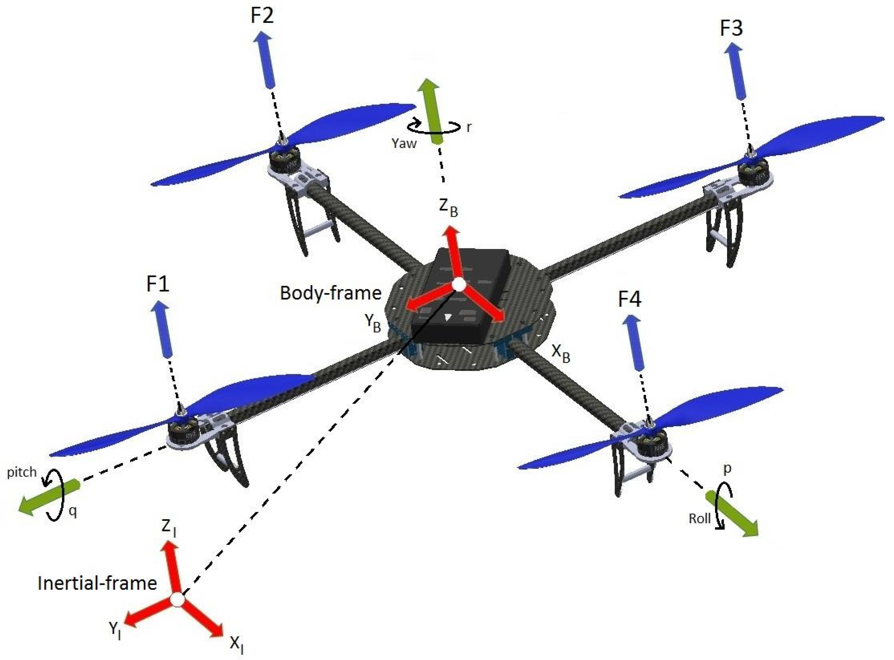
35]. To start, we consider the dynamic model of the Quadrotor aircraft as a rigid body that is actuated in force and subject to external disturbances. Consider a fixed inertial frame
, and a body frame
attached to the center of mass of the vehicle as is shown in
Figure 1. The configuration of
with respect to
can be viewed as an element of the special euclidean group
.
Adopting the standard generalized coordinates vector, which describes the position and orientation of the aerial vehicle [
4], such that the model could be separated in two coordinate subsystems: translational and rotational and considering that the dynamic model is obtained via Lagrange approach [
13] with external generalized force
on the Quadrotor aircraft. Then, the external force can be written as
where
u is the sum of mechanical thrust forces:
with
for
i = 1, 2, 3, 4,
is a constant and
is the angular speed of motor
i, as shown in
Figure 1. This force vector can be expressed in the inertial frame as
where
is the translational force applied to the Quadrotor aircraft and
is the rotation matrix, which is defined by three Euler angles
and
,
and the control torques generated by the four rotors are described by
where
l denotes the distance from the rotors to the center of mass and
d is the drag coefficient produced by coordinated reactive torque involving the four rotors because of the geometry of the Quadrotor aircraft. Now, considering the complete dynamic equations of motion for the rigid body derived through the Euler–Lagrange formalism in [
26], the equations of motion for the aerial vehicle are given by
where
x and
y are the coordinates in the horizontal plane and
z is the vertical position, whereas that
is the roll angle around the
x-axis,
is the pitch angle around the
y-axis and
is the yaw angle around the
z-axis for the vector
. Meanwhile,
J is the inertia tensor and
C is the Coriolis force acting on the Quadrotor helicopter.
3. Nonlinear Trajectory-Tracking Control
In this section, we present a nonlinear control for the trajectory-tracking of the Quadrotor aircraft based on super twisting control algorithm. The objective is to design a controller such that the tracking error converges to the origin in finite time to track a reference signal , where
is the current measurements vector.
and its derivatives are bounded for all .
the signal is available online.
In order to demonstrate the robustness of the proposed controller, we consider the Coriolis term as an uncertainty in the model dynamics, and we propose the following control input,
and we assume that
where
is the uncertainty term that result from Coriolis force that contains the gyroscopic and centrifugal terms with
, which is the maximum value of the uncertainty in a real application. Moreover,
value depends strictly on the velocity and angular positions that affect the vehicle when performing the trajectory-tracking. So, rewriting Equation (
5) and substituting (
7) into (
6), we have
The control inputs u, , and are the total thrust or collective input (directed out the bottom of the aircraft) and the angular moments, respectively.
3.1. Altitude and Yaw Control
For altitude control, we consider the dynamic in the
z-axis from (
5),
using the following control input
where the variable
is a PD controller, which is defined by
with
,
,
the altitude desired and where
,
because when
and
are
the altitude control
u is indeterminate. Then, using (
11) into (
10), we get
Now, the yaw angular position
can be controlled as in [
26] by applying
where
is the desired yaw angular position and
,
are constants for tuning PD controller in the yaw axis. Afterwards, introducing (
11) into the horizontal dynamics of (
8) and assuming that
is small enough means that the vehicle has achieved the required altitude, and hence this variable
for a time
T, so the dynamics in the axis
x and
y are
3.2. Trajectory-Tracking Control on the y-Axis
First of all, we consider the dynamics in
Roll axis given by
y-dynamic in (
16). We will implement a nonlinear controller design based on super twisting technique in order to guarantee better convergence accuracy of
,
,
y and
states. Then, if we differentiate twice, (
16) leads to
by Taylor series approximation, we have
Considering small angles
), the above expression reduces to
by replacing the first dynamic (
from Equation (
9) in the above equation, it follows
considering that
we have
where f1 (·) is the Coriolis force and
κt is the coefficient of inertia tensor, which is known. Notice that the system in (
22) represents four integrators in cascade with uncertainties, which can be observed in
Figure 2.
Additionally, if we assume external perturbations in the control input of the system (
22), we obtain,
where
is the external perturbation that exists in any realistic problem, affecting the trajectory-tracking. Moreover, the assumption considers that the dynamic system works in a small linear region (
), and the perturbations in the input of the system directly affect the stability. According with above assumption, the following inequalities are required:
for some constants
. Then, we propose a robust control algorithm motivated in the super-twisting control to ensure the stability on the trajectory-tracking under external perturbations. Therefore, we can obtain the following differential equations set,
We define tracking errors as
Trajectory-tracking will be achieved if we design a state feedback control law to ensure that
for
are bounded and converge to zero in a finite time. For instance, boundedness of
will ensure boundedness of
y because
is bounded. We need also to ensure boundedness of tracking errors. For this, we start with
where
is viewed as the control input. We want to design
to stabilize the origin. For this linear system, we can obtain this objective by
so that
where the design coefficients
to
are chosen such that the reconstruction error dynamics dominant characteristic polynomial is Hurwitz, i.e.,
Then, to design the sliding mode control, we start by designing the sliding manifold along which the sliding motion is to take place. For this trajectory-tracking problem, the sliding manifold denoted by
s is defined by the tracking errors as follows:
and
Therefore, if the control law enforces the trajectories in the phase space such that
in (
30), then the tracking errors converge asymptotically due to
where the surface
s is reached in finite time. Therefore, we can proceed by designing the control input (
) as follows,
with
where the variable
denotes the usual super-twisting component with coefficients chosen in the following manner:
and
L is the sum of disturbances that affect aerial vehicle dynamics (
). Then, we have that the closed loop error dynamics is given by:
Let us denote as
and rewrite the last equation in the form:
According to inequalities given by (
24) and considering the new variable
, let us rewrite the last equation as a differential inclusion:
Now, assume that the perturbations terms of the system (
37) are bounded by
for some constants
. Then, the origin
is an equilibrium point that is stable if the gains of the controller (
34) satisfy
Moreover, all errors trajectories () will converge asymptotically once is reached in finite time to the origin.
3.3. Stability Analysis
In order to provide stability of the equilibrium of the perturbed system (
37) in finite time, we propose the following Lyapunov candidate function obtained from [
32],
The proposed Lyapunov candidate function can be written as a quadratic form
where
and the matrix
P is defined as
Its time derivative along the solution of (
37) results as follows:
where
Using the bounds on the perturbation (
38), it can be shown that
where
with
Therefore,
is negative definite if
. It is easy to see that this is the case if the gains are as in (
39). Therefore, we can see that the control law in (
33) will drive the vehicle to the desired reference signal
, if and only if the conditions on the gains
and
are satisfied, implying that
. Therefore, it can be concluded that,
This condition ensures a stable performance of the trajectory-tracking for the small Quadrotor aircraft on the y-axis.
3.4. Trajectory-Tracking Control on the x-Axis
We will use for
x-trajectory control the same procedure used in the previous section for
y-trajectory control. We now consider the dynamics in Pitch axis given by (
15). Considering small angles in the same way as the above analysis and the fact that
in the
x-dynamics, we have
and assuming external perturbations in the control input of the system, as in the case previous
where
is the Coriolis force and
is the coefficient of inertia tensor, which is known as well as in the previous case. Continuing in the same manner, with
it can be seen that
with
We can see that the control law in (
50) will drive the vehicle to the desired reference signal
in a finite time, if and only if the conditions on the gains
and
are satisfied as in the case previous implying that
in finite time. Simulation results for trajectory-tracking of a Quadrotor helicopter using this proposed robust controller are presented below.
4. Simulations Results
In this section, we present the results obtained from a simulation run using the proposed nonlinear controller. The controller parameters for each axis
in simulation are briefly described in
Table 1 and
Table 2. To verified the robustness of the super-twisting controller, a bounded disturbance as in [
36] has been introduced to test stability for the proposed robust control.
The parameters
,
and
that involve the errors in the second order sliding mode controller for each of the axes
are tuned in the following way:
, where the value of
must necessarily be greater than the others because this value manipulates the velocity of convergence the error
, which is given by the orientation angle (
) depending on the axis that is being controlled, and it is a priority to stabilize the orientation of the vehicle to obtain adequate flight and execute the proposed trajectory tracking while the values of the gains
and
are tuned according to the parameters described in [
32].
The results of these simulations are shown in
Figure 3,
Figure 4,
Figure 5 and
Figure 6, where we show a comparison of the performance and behavior of this control strategy (super-twisting) against a PD-controller in order to demonstrate the efficiency of this type of nonlinear controller with the external perturbations added. We have handled the test results for the super twisting algorithm under the following initial conditions
, where we consider a path for each of the axes (
xy) of
m and
m with
s. Therefore, the desired trajectories for each axis described by (
52) are
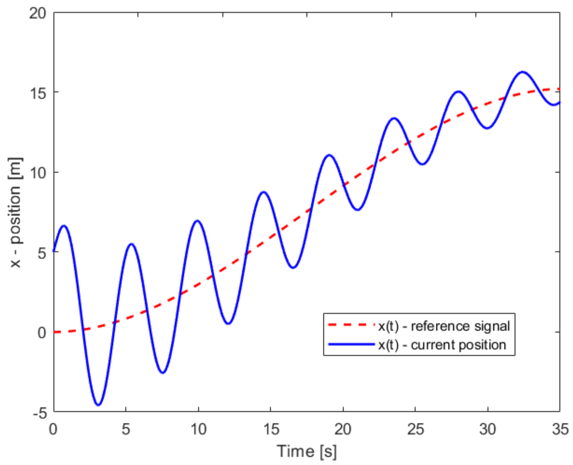
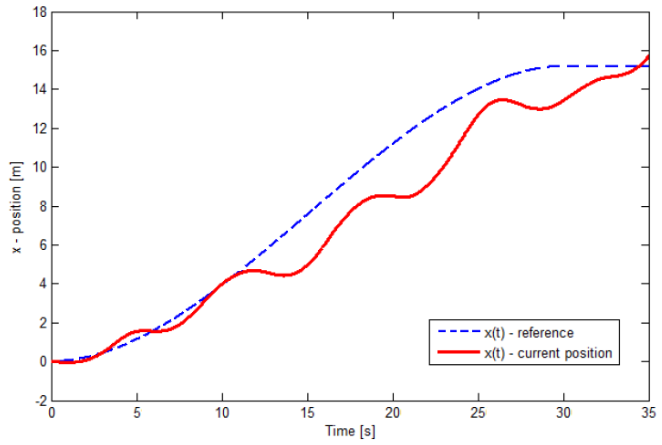
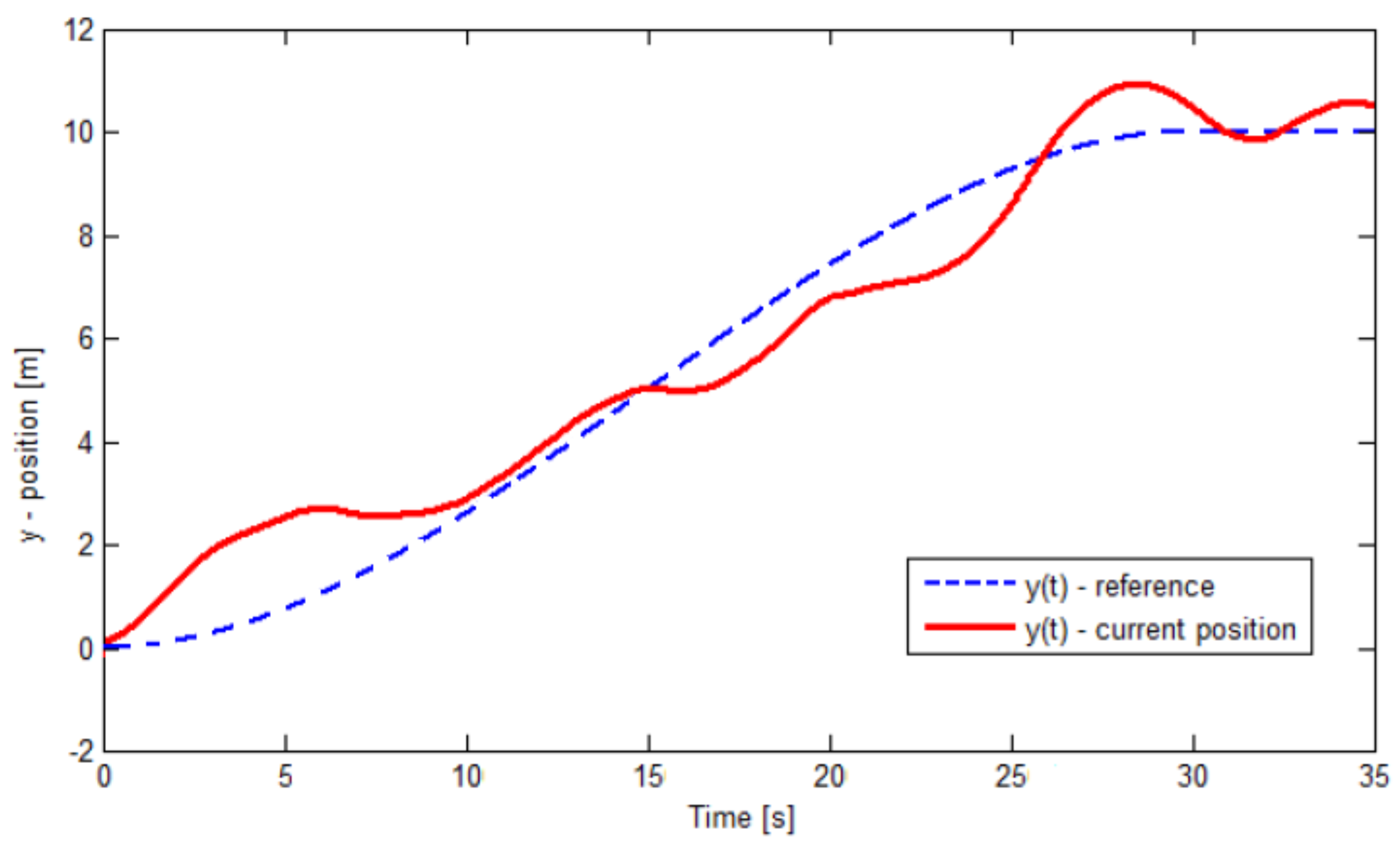
To start, we can observe in
Figure 3 and
Figure 4 the trajectory-tracking control using a PD-controller for the axes
x and
y, respectively. In these figures, it can be seen that the current position of the Quadrotor helicopter described by Equation (
52) oscillates around the given reference, which indicates a poor performance because it never manages to converge to the stipulated reference. This happens in both cases for the
x and
y axes. Moreover, in
Figure 4, a small improvement in the performance of the controller can be noted, but it is not sufficient to bring the helicopter to the proposed trajectory
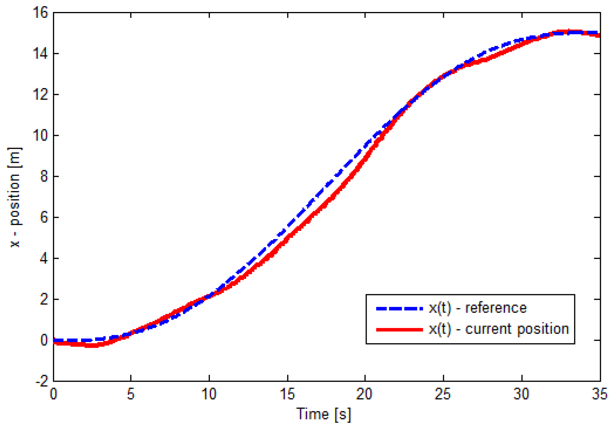
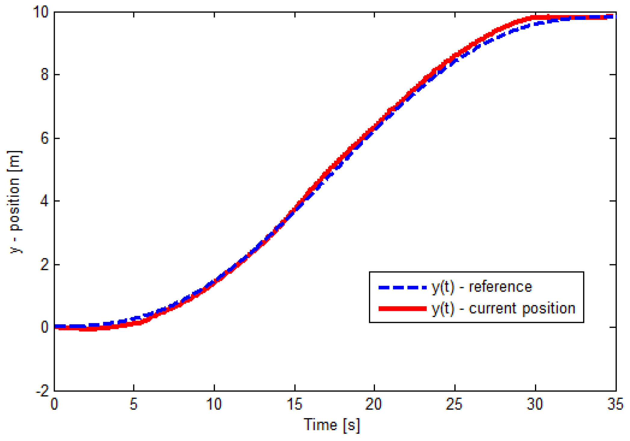
efficiently. However, the second order sliding mode approach has the Quadrotor helicopter follow the proposed path effectiveness on the
x-axis, as can be seen in the
Figure 5. Notice that the actual position (trajectory) converges faster to the desired reference signal even under external perturbations. In the same way, in
Figure 6, this response, which describes the behavior in the
y-axis at the moment is described. We can conclude based on these two last Figures that the proposed nonlinear controller renders the Quadrotor helicopter following the designated trajectory under external disturbances using the super-twisting control satisfactorily. In addition, the super-twisting algorithm implemented through mathematical models was converted to their respective Simulink models for ease of simulations.
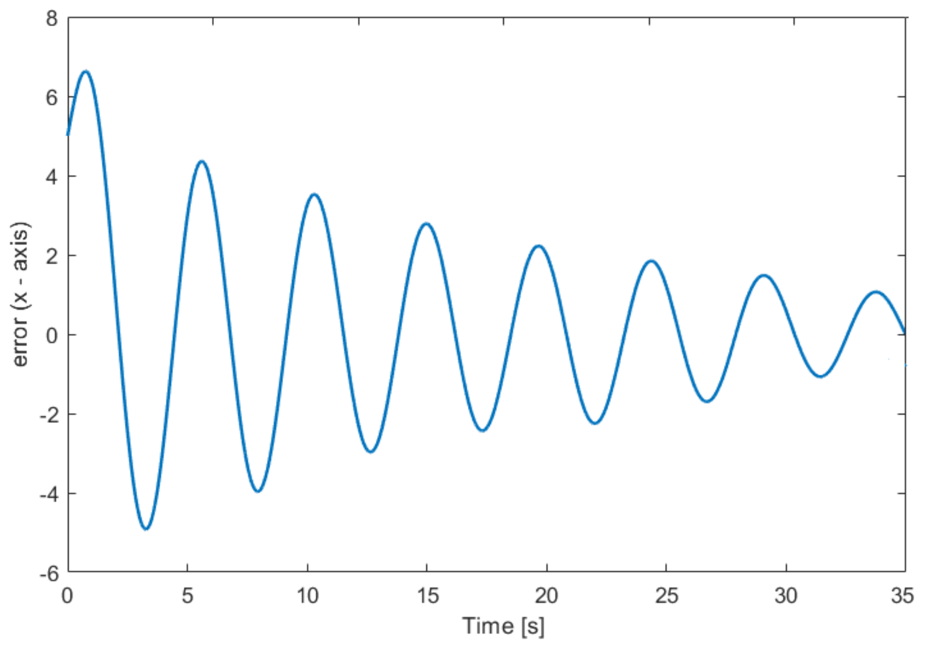
Additionally, in the following
Figure 7,
Figure 8,
Figure 9 and
Figure 10, the errors of the trajectory tracking can be observed, which indicates the input trajectories against the output trajectories that are presented in each of the axes applying the PD control and the super twisting controller. This is done in order to better evaluate the tracking performance of the proposed trajectories in the Quadrotor helicopter. It can be seen how the super twisting controller improves the performance of the trajectories, reducing the oscillations observed in the PD control, considerably.
This robust control can improve the trajectory-tracking, combining and selecting different values of gain in the super twisting controller to get better tracking of the reference signal (see
Figure 6). Notice that, from
Section 4, the control law (
33) and (
50) will drive the aerial vehicle to the desired reference signal
. In addition, we know that this kind of nonlinear technique presents the so-called chattering phenomenon in its response to trajectory-tracking with respect to time, which is something that characterizes this control law. However, this phenomenon can be reduced by an approximation of the sign function with a hyperbolic tangent signal as in [
12].
5. Real-Time Experiments
In order to validate the control law developed in the
Section 3, a smooth piecewise continuous trajectory as reference signal
is suggested for the Quadrotor helicopter defined by the following polynomial function,
As a example, we can consider the dynamics on the
y-axis given by
where the trajectory initial conditions are as in [
2],
where
is the length of the path for the
y-axis and
is the total route time. Similarly, we have the same procedure for the dynamics in the
x-axis. These equations that describe the trajectories to be followed by the Quadrotor helicopter have been programmed in the autopilot subject to external disturbances in order to demonstrate the performance of the proposed robust algorithm. The X4-prototype setup to verify these tests is shown in
Figure 1, whereby a carbon fiber frame coupled with two brushless motor pairs of MULTISTAR 4220–880 Kv and two ESC (Electronic Speed Controller) pairs of 30 A capacity. The sampling period is 10 ms and the altitude was fixed by the operator using a Futaba 2.4 GHz FASST radio system for transmitting the control signals. Several test cases were completed in the Quadrotor helicopter built to evaluate the efficiency of this type of robust controller with the following initial conditions
and
and a path given by
m and
m with
s.
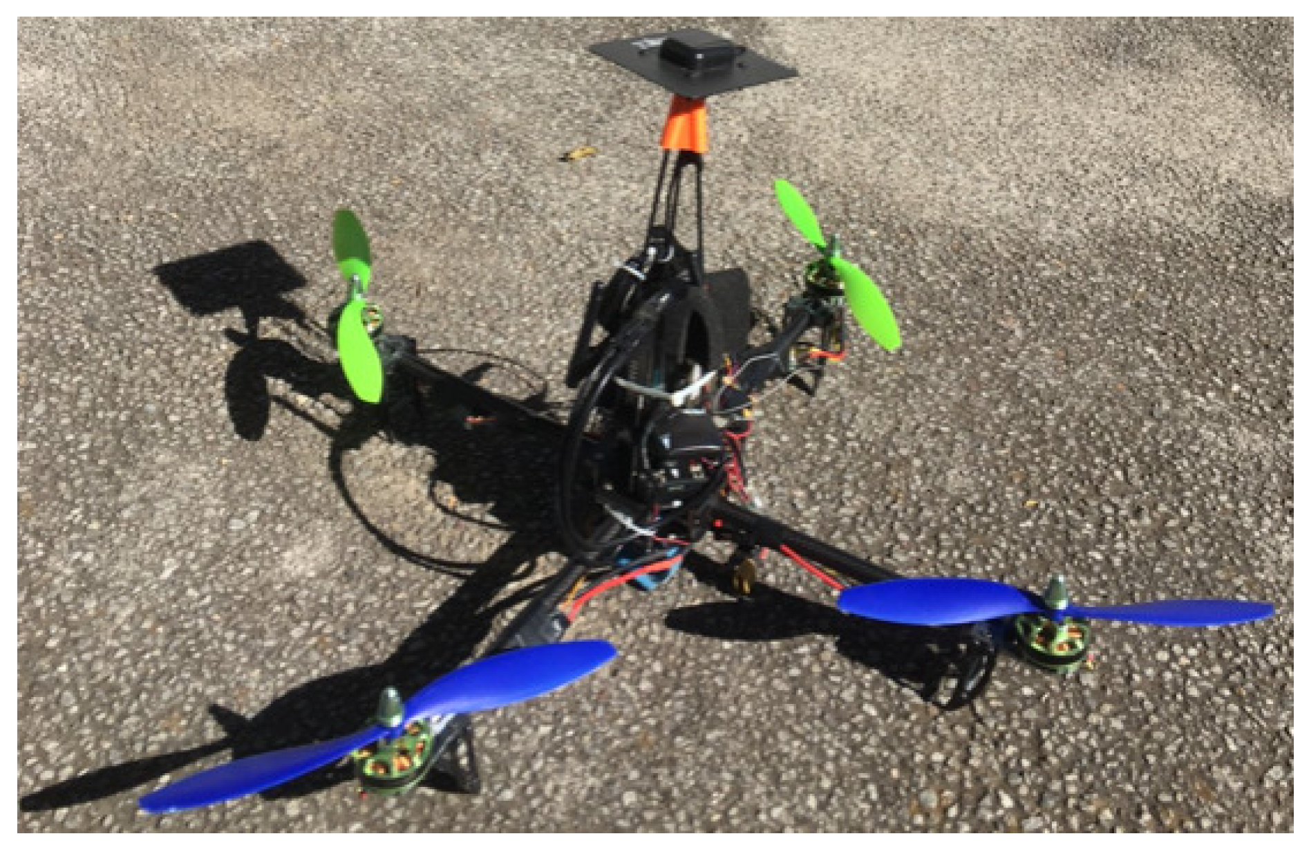
The second order sliding modes approach described in
Section 3 is then implemented in C++ environment and run in real-time on the Pixhawk module which is embedded in the X4-prototype setup (see
Figure 11). The best gains found experimentally for each axis (
xy) based on the super-twisting algorithm are shown in
Table 3 and
Table 4, while gains
and
were calculated by averaging the measurements of the recorded wind velocity (L-disturbance) at the time of testing outdoors. In order to adequately compare the performance of the second order sliding mode controller against the PD control, the experiments were carried out outdoors measuring the speed of the wind with an anemometer in order to execute the flights under the same conditions (≈3 m/s) and clearly observe the improvement that is obtained when applying super-twisting controller.
It should also be noted that for the experiment reported in this section, the gains reported in the previous tables are different for both axes due to the fact that the aerial vehicle presents different physical characteristics, which implies an adjustment of independent gains in each of its axes (
xy). The results of these experiments are shown in
Figure 12,
Figure 13,
Figure 14 and
Figure 15.
Two sequences of experiments were performed. In the first experiment, a PD control was used, while for the second experiment an second order sliding mode control (super twisting) was employed in order to compare the good performance of the nonlinear control against a conventional control such as the PD technique.
Figure 14 and
Figure 15 shown flight-recorded data of the response of the trajectory-tracking on the
x and
y axes employing the super twisting control with efficient performance under external disturbances (wind gusts) by keeping track of near the trajectory traced in order to achieve the correct tracking of the programmed path. Meanwhile,
Figure 12 and
Figure 13 shown the PD-control behavior in the Quadrotor helicopter. Then, we can say that the experimental results obtained from autonomous flight tests for the trajectory-tracking carried out in an outdoor environment using super twisting algorithm were satisfactory where the current position converges quickly and appropriately to the reference signal in comparison with the results of the PD-controller. Therefore, from
Figure 12,
Figure 13,
Figure 14 and
Figure 15, it can be shown the benefits offered by this nonlinear approach in real-time applications based on a correct tuning of the gains in the controller. On the other hand, it is possible to observe that there exists the characteristic chattering phenomenon of this proposed controller; however, notice that its effect on trajectory-tracking is minimal.


