Article

A Novel UAV Visual Positioning Algorithm Based on A-YOLOX

Department of Intelligent Manufacturing, Wuyi University, Jiangmen 529020, China
*
Author to whom correspondence should be addressed.
Drones 2022, 6(11), 362; https://doi.org/10.3390/drones6110362
Submission received: 12 October 2022 / Revised: 5 November 2022 / Accepted: 14 November 2022 / Published: 18 November 2022
(This article belongs to the Special Issue Intelligent Image Processing and Sensing for Drones)

Abstract

:
The application of UAVs is becoming increasingly extensive. However, high-precision autonomous landing is still a major industry difficulty. The current algorithm is not well-adapted to light changes, scale transformations, complex backgrounds, etc. To address the above difficulties, a deep learning method was here introduced into target detection and an attention mechanism was incorporated into YOLOX; thus, a UAV positioning algorithm called attention-based YOLOX (A-YOLOX) is proposed. Firstly, a novel visual positioning pattern was designed to facilitate the algorithm’s use for detection and localization; then, a UAV visual positioning database (UAV-VPD) was built through actual data collection and data augmentation and the A-YOLOX model detector developed; finally, corresponding high- and low-altitude visual positioning algorithms were designed for high- and low-altitude positioning logics. The experimental results in the actual environment showed that the AP50 of the proposed algorithm could reach 95.5%, the detection speed was 53.7 frames per second, and the actual landing error was within 5 cm, which meets the practical application requirements for automatic UAV landing.

1. Introduction

Public security, a critical field of national security, correlates strongly with personal interests and property safety. With its national economic development and modernization, China has been assigning more and more importance to public security. With the advantages of high flexibility, maneuverability, stealth, independence from the geographical environment, being low cost, and having the ability to carry different processing equipment, UAVs have been used for identification and detection in such areas as urban inspection [1], fire monitoring [2,3,4,5], criminal investigation and counter-terrorism [6], normal security patrolling [7], epidemic prevention and control [8], post-disaster rescue [9,10], agricultural inspection [11,12], and power inspection [13,14]. For example, UAVs can be used in agriculture for mapping farmland, spraying pesticides, seed sowing, monitoring crop growth, irrigation, pest diagnosis, artificial pollination, and much more. The use of UAVs greatly reduces working time and increases production efficiency, thus promoting the development of intelligent agriculture [15,16]. As UAVs are widely used in military and civil fields, their intelligent application has become a development trend, and autonomous positioning landing is the basis for realizing intelligent UAVs. With the efforts of researchers in recent years, UAV landing technology has made significant progress, but there are still some limitations. For example, GPS-based methods fail in places where there is no GPS signal [17], and traditional image recognition-based methods have poor recognition effects and poor stability in environments with changing light and complex backgrounds [18]. Therefore, research on a visual positioning algorithm for UAVs has important application value and diverse application scenarios.
In this study, we started from the above problems and strove to find relevant solutions to achieve accurate landing with UAVs. Compared to traditional methods, our method offers several advantages. First, the detection model uses an anchor-free target detection algorithm, which is much faster. The FPS can reach 53.7, which meets the requirements of real-time detection. Second, in comparison with previous methods [19,20,21], our method possesses much higher actual landing accuracy. Third, we introduce deep-learning methods into the UAV landing process, which are characterized by powerful feature extraction and characterization capabilities. This significantly improves the detection performance of the model, which is able to undertake detection accurately despite light changes, scale changes, and wind impacts and shows better robustness. In summary, this paper makes the following contributions:
  • During the process of UAV landing, when moving from high to low altitudes, the visual imaging constantly changes, and the pixel area of the target pattern gradually increases, which poses a great challenge for target detection. Therefore, we developed high- and low-altitude visual positioning algorithms to achieve stable detection with UAVs throughout the process of moving from high to low altitudes;
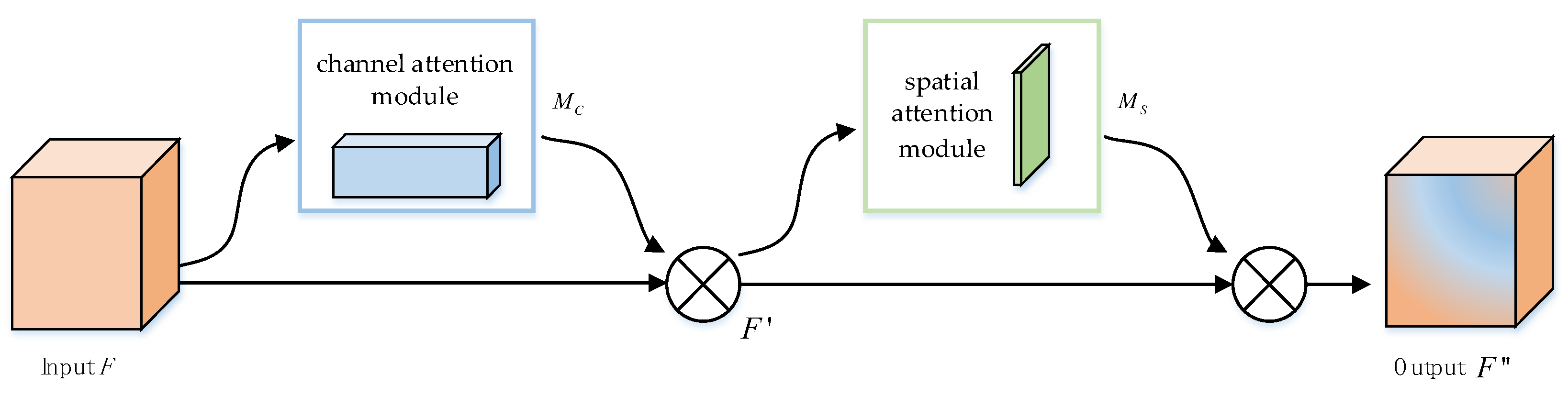
  • To solve the problem of poor detection of small- and medium-sized targets with the model, we supplemented the YOLOX algorithm [22] with an attention mechanism and proposed the attention-based YOLOX (A-YOLOX) detection algorithm, which improves the detection performance of the model for small- and medium-sized targets;
  • We collected 6541 actual images under different conditions and expanded the data with data synthesis techniques in order to compile the UAV Visual Positioning Database (UAV-VPD), a database applicable for UAV landing scenarios;
  • Extensive experiments were carried out with the newly created database and in the real environment, and our model proved to be robust. Our model achieved an actual landing accuracy within 5 cm, and the FPS reached 53.7, which meets the requirements of real-time detection.
The organization of the remaining sections is as follows: Section 2 concerns related work, describing current approaches to autonomous positioning and the existing problems; Section 3 describes the visual positioning algorithm proposed in this paper in detail; Section 4 presents the experiments and discussion; and Section 5 is devoted to conclusions and future work.

2. Related Work

Autonomous positioning landing is generally divided into visual positioning landing [23] and satellite navigation landing [24]. Satellite navigation landing is a traditional UAV positioning technique that uses the Global Positioning System (GPS) for positioning, and it is suitable for long-duration tasks [25,26]. However, there are some limitations in satellite navigation landing, such as easy signal loss in scenes with more occlusions, the lack of a guarantee of stability, and low accuracy [27,28], meaning that it cannot meet the requirement for centimeter-level error.
UAV visual positioning landing mainly relies on image sensors and uses image processing technology to achieve an accurate landing, and this is a research hotspot for scholars in China and abroad. Sharp et al. [19] proposed a precision landing system for the autonomous landing of multi-rotor UAVs. This system uses a large square and five small squares as landmark patterns. The landing process starts with initial recognition through the large square and then combines image processing techniques, such as feature point extraction, area segmentation, and motion estimation, to guide the UAV to land. Lange et al. [29] put forward a method for UAV landing based on a moving target plate with a landmark pattern consisting of a black, square hexagon and four white concentric circles, using optical flow sensors to acquire the velocity of the moving target and, thus, track the moving target, while the flight altitude of the UAV is acquired from the size of the landmark pattern imaging. Marut et al. [20] introduced a simple and low-cost visual landing system. The system uses Aruco markers and obtains candidate marker points by extracting contours, filtering, and other image processing techniques and then compares them with a marker dictionary to determine the location of the markers. Yuan et al. [21] proposed a hierarchical vision-based open landing and positioning method for rotary wing UAVs. This method defines the landing of UAVs as “Approaching”, “Adjustment”, and “Touchdown” and develops the corresponding detection and positioning systems for these three phases. In addition, a federated Extended Kalman Filter (EKF) is designed to evaluate the attitude of UAVs. Zhou et al. [23] designed a monocular camera-based AprilTages visual positioning algorithm for UAV positioning and state estimation. They design a number of different sizes of labels to enable UAVs to position themselves at different altitudes. Xiu et al. [30] proposed a tilt-rotor quadrotor model for autonomous landing, which controlled the motor direction by using four servos so as to control UAVs’ positions and attitudes, achieving tilt-rotor parking and tilting flight. This model controls UAVs’ positions and attitudes more precisely, which enables a more effective landing for UAVs. Sefidgar et al. [31] designed a landing system with sensors that consisted of four ToF sensors and a monocular camera. First, the features of the AprilTag pattern are extracted by the designed algorithm to find the center point and calibrate it. Then, the sensor contacts are used to set up coordinate equations, and focal lengths in X and Y directions are solved to derive the coordinates of the ground pattern. With the continuous research and exploration of researchers, traditional image processing algorithms have undoubtedly made great efforts to improve the accuracy of UAV landing. However, their good performance depends on a good imaging environment, and the algorithm’s performance will be significantly degraded under the situations of insufficient light, complex background, occlusion, scale transformation, etc. It is difficult to meet the actual demand for centimeter-level landing errors for UAVs in different scenes. Table 1 shows the comparison of different visual landing methods.
Deep learning methods have been developed rapidly in recent years [32,33]. In 2014, Girshick et al. [34] proposed RCNN (Region-based Convolutional Neural Networks, RCNN) and introduced deep learning into target detection for the first time, opening a new chapter for target detection. Deep-learning-based target detection algorithms have also become a hot topic for scholars in recent years. Many scholars have successively proposed two-stage detection networks such as SPPNet (Spatial Pyramid Pooling in Deep Convolutional Networks, SPPNet) [35], FastR-CNN, and FasterR-CNN [36], which use RPN (Region Proposal Network, RPN) [37] to generate a large number of candidate frames to improve the recall rate, and the confidence of these candidate frames is not utilized in the inference stage, which reduces the inference speed. In 2016, Redmon et al. [38] proposed the first version of the YOLO (You Only Look Once, YOLO) series of single-stage networks, YOLOv1, which surpassed the detection speed of two-stage detectors. Moreover, its accuracy is continuously improveed by subsequent researchers, which is comparable to that of two-stage detection networks, meeting the requirements of most industrial scenarios. As a result, the YOLO series has also become the mainstream target detection algorithm in the industry. Deep learning models have powerful learning and characterization capabilities, and their utility and generalization capabilities are stronger [39,40]. Therefore, they are considered to be introduced into the autonomous landing process of UAVs in order to solve the various environmental interference problems mentioned and to further improve the detection speed.

3. Methods

According to the different visual imaging of UAVs at different altitudes, this paper designs a high-altitude visual positioning algorithm and a low-altitude visual positioning algorithm to guide UAVs to land accurately. When UAVs return to the vicinity of the target point, they automatically adjust the direction of the camera, return the video captured by the camera, detect it by a trained detector, and output the number and coordinates of special patterns of the image. The visual positioning algorithm automatically selects a high-altitude positioning algorithm or a low-altitude positioning algorithm by calculating the area and number of patterns. The algorithm flow is shown in Figure 1.

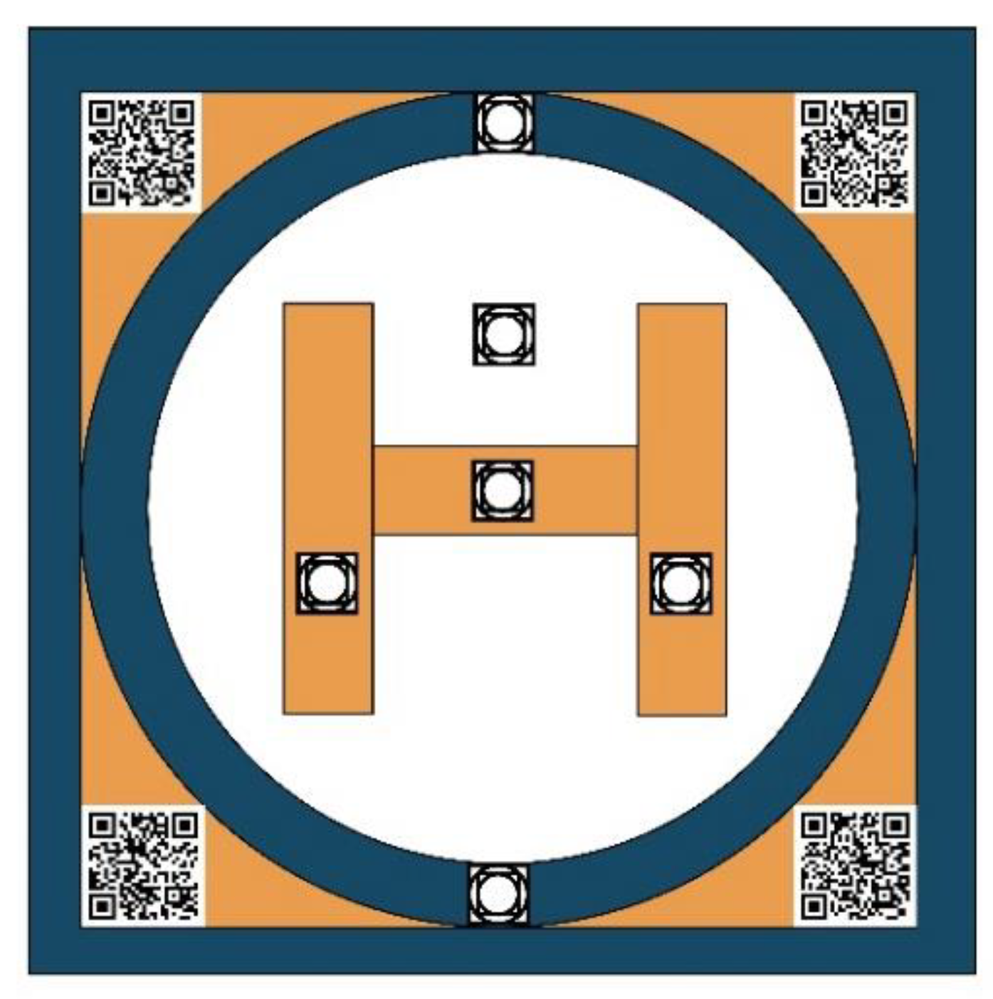
3.1. The Construction of UAV-VPD

A pattern that facilitates fast recognition for a detection algorithm is an important condition for UAVs to land accurately at the designated location. When the UAV flies over the landing point, it obtains ground information through the camera and then adjusts its orientation and lands toward the target point after valid information is detected. The design of the visual positioning pattern mainly follows two principles: feature discriminability and visual imaging adaptability. Feature discriminability: in order to make the model easy to recognize, the basic circular and square patterns are used in designing visual positioning patterns. However, the single basic pattern is not conducive to feature discrimination, so the circles and squares are combined inline to improve feature discriminability; visual imaging adaptability: there are two stages in the landing process of the UVA: high-altitude phase and low-altitude phase. Since the visual imaging of the UAV changes continuously during the landing process and the pixel area of the target pattern gradually increases, in order to avoid the loss of the visual pattern due to the narrow field of view of the UAV at low altitude, the designed positioning pattern adopts the mutual fusion of large and small patterns. In other words, six small patterns are added inside a large pattern, whose structure is similar to the large pattern. It is worth noting that with such a design, end-to-end high- and low-altitude visual positioning can be achieved with only one model so as to complete an efficient UAV parking and landing process. In actual application scenarios, for the weak GPS signal, UAVs will pre-bind QR codes on the apron to assist themselves in finding the location of visual positioning patterns. The visual positioning pattern is shown in Figure 2.
To construct the UAV-VPD, we printed the designed patterns onto KT plate and then manually operated the UAV to fly and shoot the patterns. During the shooting process, since the adjacent frames of the video have extremely high similarity, we tried to put the KT plate in different positions of the frame during the acquisition process instead of simply having the KT plate presented in the center of the video frame. Furthermore, for the sake of improving the fit of the data in actual application scenarios, videos of different scenes, different periods, different heights and angles were collected during data collection; then, a total of 6541 images were obtained after video split-frame processing and data cleaning; finally, the visual positioning patterns were labeled by the open source labeling software. Remarkably, when the UAV returns to a relatively high position over the target location, only the outer frame of the visual positioning pattern needs to be marked. When the UAV is at low altitude, the six small marker patterns on the visual positioning pattern can be clearly seen, so all the markers within the field of view need to be marked. Some of the collected data are shown in Figure 3.
Since the scenes of UAV inspection are varied, simply relying on manual acquisition and labeling requires a lot of labor and material costs, and the scenes are also relatively single, which cannot well fit the real situation of different scenes during UAV inspection. Therefore, we use data synthesis technology to expand the data of scenes that are difficult to collect and use the synthesized data together with the real data for model training so as to improve the accuracy and strengthen the robustness and generalization ability of the model. The data synthesis uses the copy-paste method [41]. Firstly, 970 background images with high semantic similarity from different scenes are collected from the Internet using crawler technology, and then the visual localization patterns are randomly copied and pasted onto these background images, and the corresponding pattern coordinate information is extracted, which no longer needs to be re-labeled manually. When UAVs are at a low altitude and an ultra-low altitude, their imaging pictures only have recognition patterns and no other objects, and only at a high altitude will other objects be recognized, so we only need to synthesize the high-altitude data. Some of the synthesized data are shown in Figure 4.
The data of 6541 images collected from real scenes are combined with the synthetic data of 970 images to form the UAV-VPD. A large number of images are needed for testing to achieve an efficient model performance evaluation, so the training set, validation set, and test set are divided in the ratio of 2:2:6. The details are shown in Table 2.

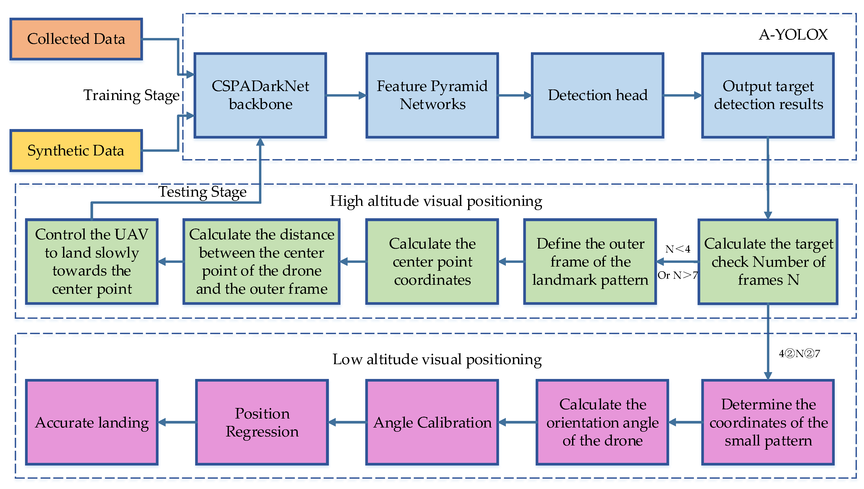
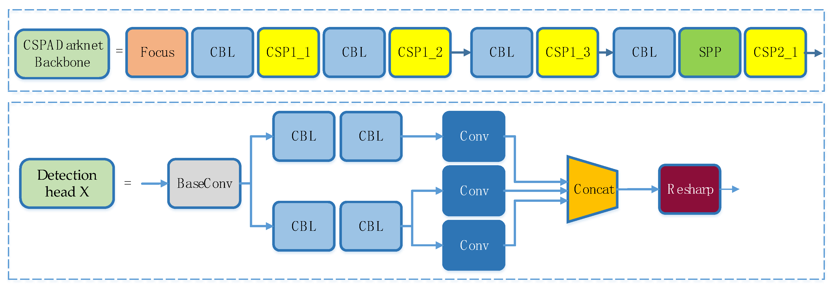
3.2. Object Detection Algorithm A-YOLOX

The proposed target detection algorithm A-YOLOX is based on YOLOX with the addition of CBAM (Convolutional Block Attention Module) [42], allowing CBAM to be used throughout the backbone network part of the depth model. The CBAM contains two separate submodules, a channel attention module, and a spatial attention module, which perform “attention” on the channel and space, respectively. The module structure is shown in Figure 5.
Assuming an intermediate feature graph F is input, FRC×H×W, CBAM first performs global maximum pooling and average pooling of F by channel, sends the pooled two one-dimensional vectors into the fully connected layer operation and sums them to generate one-dimensional channel attention M C R C × 1 × 1 ; then, multiply M C with the input element F to obtain the channel attention-adjusted feature graph F . Secondly, F is conducted global maximum pooling and average pooling by space, and the two two-dimensional vectors generated by pooling are stitched together and subjected to convolution operation to eventually generate two-dimensional spatial attention M S R 1 × H × W . Finally, the output feature F is obtained by multiplying M S with F by elements. The CBAM generation attention process can be described by Equations (1) and (2), where denotes the corresponding element multiplication.
F = M c ( F ) F
F = M S ( F ) F
The A-YOLOX network is mainly composed of three parts, which are CSPADarkNet (Cross Stage Partial Attention DarkNet, CSPADarkNet) backbone network, FPN (Feature Pyramid Networks, FPN) [43] feature fusion network, and detection heads, as shown in Figure 6. DarkNet is a classical deep framework, which is often used as the backbone network for feature extraction in the YOLO series. Its design process borrows the idea from residual network ResNet [44] to prevent the gradient from disappearing during the deepening of the network by adding the residual module to the network, which is beneficial to the fast convergence of model training. In this paper, CSPDarkNet [45] is used and combined with CBAM attention mechanism to form CSPADarkNet backbone feature extraction network, the output of which is three effective feature layers. The three effective feature layers are then fused by the FPN network, and finally, three different scales of features: 20 × 20 × 512, 40 × 40 × 256, and 80 × 80 × 128 are output for target classification and localization. The detection head of A-YOLOX determines whether there is an object corresponding to it at the feature point by the three feature graphs output by FPN. The structure of CSPADarknet and the refinement network structure of the detection head are shown in Figure 7 and Figure 8.
Since the detection head of the network respectively predicts the category, location, and object boundary frame, the loss function of the network consists of three parts: the category loss Lcls, the location loss Lreg, and the object boundary frame loss Lobj. Lcls and Lobj adopt the cross-entropy loss, and Lreg adopts the IoU loss. The formula for calculating the total loss is shown in Equation (3).
L = L c l s + λ L r e g + L o b j N p o s
In the above equation, λ refers to the balance coefficient of the location loss and N p o s refers to the positive sample number. The A-YOLOX algorithm employs several training strategies during the training process, such as Exponential Moving Average (EMA), cosine annealing learning rate, and IOU loss, and uses the means of data enhancement such as mosaic, horizontal random rotation, and color change.

3.3. The Design of High- and Low-Altitude Visual Positioning Algorithm

3.3.1. High-Altitude Visual Positioning Algorithm

As GPS navigation technology is relatively stable in wide-open areas, when UAVs receive return instructions at a high altitude, we first use GPS positioning technology to return the UAVs to a high-altitude position a few dozen meters from the marker pattern. Then, the landing position can be determined only by recognizing the outer frame of the visual positioning pattern designed in this paper. The detection algorithm is called in real-time for recognition, and when the algorithm recognizes the target object, it outputs information such as the number and coordinates of the target frame in real-time. The high-altitude positioning algorithm calculates the target frame area A, confidence degree P, and comprehensive score S from the information output by the detector, and the target frame with the highest comprehensive score is the landing position for the target. After the target frame is determined, the relative distances dx and dy between the central point of the UAVs and the central point of the target frame can be calculated so as to call UAV flight control module to allow UAVs to descend slowly toward the center of the pattern. The UAV flight control adopts PID control mode, and its control quantity is calculated according to Equation (4).
u ( k ) = K P e ( k ) + K I i = 0 e ( i ) + K D [ e ( k ) e ( k 1 ) ]
In the above equation, KP refers to the proportional coefficient, KI refers to the integral time constant, and KD refers to the differential time constant. The target detection algorithm continuously detects and updates dx and dy, and the flight control algorithm updates e(k), the deviation distance between the current position and the target position, according to dx and dy to obtain the control quantity u(k) output by the PID controller, so that UAVs can quickly and steadily approach the target position until they reach the ideal position. The flow of the high-altitude visual positioning algorithm is shown in Algorithm 1.
Algorithm 1. High-Altitude Visual Positioning Algorithm.
Step 1Call the target detection algorithm for the first detection when UVAs return over the landing site to obtain the position of center point of the camera carried by UAVs as ( x c , y c ) .
Step 2a. Take the detected target as the target landing point when only one outer frame of the visual positioning pattern is detected.
b. Calculate the confidence degree of each detected target when two or more outer frames of the visual positioning pattern are detected, and score the target frame with the higher confidence level by the equation S = 0.5 × A + P, thus the target frame with the highest score being the landing point.
Step 3Calculate the relative distance between the center point of the camera and the center point of the visual positioning pattern by equations dx = xcwidth/2, and dy = ycheigth/2.
Step 4Calculate the control quantity according to u ( k ) = K P e ( k ) + K I i = 0 e ( i ) + K D [ e ( k ) e ( k 1 ) ] to lead UAVs closer to the target position.
Step 5Repeat steps 2 to 4.

3.3.2. Low-Altitude Visual Positioning Algorithm

During the slow descent of UAVs, the visual field of the camera will slowly become narrower, and the outer frame of the pattern will slowly disappear on the imaging. Therefore, this paper designs a low-altitude positioning logic algorithm according to the actual situation. The algorithm mainly post-processes the identification results of the six small logo patterns given by the detector.
When UAVs land at a low-altitude position, firstly, the angle should be calibrated. Assuming the visual imaging of UAVs is shown in Figure 9, set the coordinates of point A as ( x 1 , y 1 ) , point B as ( x 2 , y 2 ) , point C as ( x 3 , y 3 ) , and point O as ( x , y ) . Calculate vector | A B | , | A C | , and | B C | to determine whether the triangle is isosceles triangle, and find the vertex (assumed to be A) and the bottom side of the isosceles triangle, and the midpoint D ( x 4 , y 4 ) of the bottom side; then, the vector | A D | is the most optimal direction for UAV’s landing. The midpoints of the upper and lower edges of the screen are P1 and P2, respectively, and the vector | P 1 P 2 | is the current orientation for UAVs. Therefore, our main task is to control UAVs to make attitude adjustments so that the pinch angle θtends to 0. θ is calculated as shown in equation (5).
θ = arg cos ( A D , P 1 P 2 ) | A D | | P 1 P 2 |
After UAVs have completed angle correction, they need to perform position regression, which is to find the coordinates of the best landing point. As can be seen from Figure 9, in the case that the angle correction has been completed, the detection frame at the top of the isosceles triangle is the point we need.

4. Results and Discussion

This experiment is conducted on the ubuntu 18.04 system with Intel Xeon(R) E3-1241 [email protected] GHz processor. Its running memory is 24 Gb, the graphics card is NVIDIA GTX1080, the video memory is 8 Gb, and the parallel computing framework version is cuda10.2.
To evaluate the model performance, we use the target detection evaluation metrics of the COCO database as our evaluation metrics in this paper. AP50 and AP75 are the average accuracy at IoU = 0.5 and IoU = 0.75, respectively. mAP is the average of the average accuracy of the IoU from 0.5 to 0.95, in a step length of 0.05. The detection speed is evaluated by Frames Per Second (FPS).

4.1. Experiment to Verify the Validity of Synthetic Data

To improve the accuracy and generalization of the model, we start with the data and fit as many real-world application scenarios as possible. We also increase the number and complexity of the training set. However, it is not easy to obtain the data in the actual scenes, which are usually collected and labeled manually, requiring extremely huge manpower, physical resources, and time costs, so we start from synthetic images and synthesize the data of different scenes similar to the actual scenes offline.
In this paper, there are 1557 images in the training sets, of which 970 are synthetic images and 587 are real images. Both the validation set and the test set are actual acquisition data.
As can be seen from Table 3, the AP50 is 51.8% when obtained by training with only 970 synthetic images. Since the synthetic images only include the high-altitude part of the scene, but the test set contains both high-altitude and low-altitude images, so the accuracy of the test is not very high, yet it is sufficient to show that the synthetic data is effective for the detection algorithm. Adding synthetic data and real data together to the training can reach an accuracy of 95.5%, which is nearly 3% higher than when training with only real data.

4.2. Experiments on Attention Mechanism

The attention mechanism was introduced mainly to enhance the poor effectiveness of the model on small and medium targets. It is desirable to validate the detection performance of the model on small, medium, and large targets so as to exhaustively verify the effectiveness of our model.
As shown in Table 4, the attention mechanism is beneficial to improve the detection accuracy of small and medium targets by 0.5% and 2%, respectively, which is helpful for UAVs to accurately identify the visual localization pattern at a high altitude and accurately locate the small graphs in the visual localization pattern at a low altitude. Since there are more computational parameters after the introduction of the attention mechanism, the FPS is much lower, but the speed of 53.7 frames per second can still meet the requirements of real-time detection.

4.3. Performance Comparison Experiments of Target Detection Algorithm

This paper researches the target-detection-based UAV vision localization algorithm. The detector in the vision localization algorithm can be replaced with arbitrary target detection models. To demonstrate the superiority of A-YOLOX, experiments are conducted to compare it with the target detection algorithms commonly used today. The backbone network of each model in the experiments is DarkNet53; the Epoch is 300. The learning rate is set to 0.01, and the BatchSize is 8. To be fair, all parameters are used with the same hyperparameter.
As can be seen from Table 5, A-YOLOX has a distinct advantage in the AP50 and mAP metrics, and its accuracy rate exceeds that of other models, especially in the mAP metric, which reaches 77.3% more than 10 points higher than other models. RetinaNet’s AP50 reached 93.4%, which is very similar to A-YOLOX’s 95.5%, but its FPS is only 6.89 frames per second, which cannot satisfy the demands of real-time detection. Taken together, the A-YOLOX offers the performance of both detection efficiency and accuracy.

4.4. Drone Actual Landing Experiment

We deployed the trained model to the local server for the actual landing test. In order to measure the deviation size of the actual landing point of UAVs more intuitively, the coordinate system was established with the vertex of the isosceles triangle in the visual positioning pattern as the reference point, the direction of the UAV nose as the positive Y-axis direction and the 90° clockwise rotation as the positive X-axis direction. The data and pictures recorded during the return flight of the UAV are shown in Table 6 and Figure 10.
According to the above data, the average deviation value μ x of the UAV in the X-axis direction can be calculated as 2.56cm, the average deviation μ y in the Y-axis direction as 2.0 cm, and the variance σ x and σ y in the X-axis direction and Y-axis direction are 4.07 and 2.40, respectively. Overall, our UAV’s positioning algorithm achieves a centimeter-level landing error, which meets the industry precision positioning landing requirements. However, during the descent process, as it will inevitably be affected by the external airflow and its own wind field generated by the high-speed rotation of the UAV wings, the UAV tends to sway from side to side, so the landing position in the X-axis direction changes a bit more.
Actually, we conduct landing tests on sunny and cloudy days, as well as in the morning, noon and afternoon. As shown in Figure 10, the pictures numbered 01, 07, 08, 09, and 10 are the landing results in a strong light environment, while the rest are the landing results in a non-strong light environment. The tests are carried out in different areas, such as car parks, intersections, and rooftops. After calculation, it can be seen that in the non-bright light environment, the average deviation μ x in the X-axis direction is equal to 2.24 cm; the average deviation μ y in the Y-axis direction is equal to 3.32 cm, the variance σ x is equal to 1.29, and σ y is equal to 1.88. In comparison, in the bright light environment, the mean deviation μ x is equal to 2.86 cm in the x-axis direction, μ y is equal to 0.68 cm in the y-axis direction, and the variance σ x is equal to 6.66 and σ y is equal to 0.6. The difference in average landing accuracy between the two conditions is small, but the stability of the UAV landing in non-bright light conditions is much better than in bright light conditions. However, in terms of overall landings, our UAV positioning algorithm achieves centimeter-level landing errors in both bright light and non-bright light conditions.
During the actual test process, we find that the ambient wind has an effect on the UAV landing. The landing time of UAVs becomes longer as the wind increases. The main reason is that the wind makes UAVs sway, so the flight control algorithm has to constantly adjust UAVs’ position according to the target detection results in order to land UAVs in an accurate position. Therefore, the constant adjustment process will cause a longer landing time. Fortunately, the target detection algorithm is still able to accurately detect the target frame of the visual positioning pattern under these circumstances. Thus, the visual positioning algorithm still shows good robustness under the influence of light changes, scene changes, and ambient wind.

5. Conclusions and Future Work

The combined application of UAV technology and computer vision technology is of great value and research significance in both civilian and military fields. In this paper, in order to improve the accuracy of automatic landing for UAVs, based on the actual situation that the performance of traditional image processing algorithms is sensitive to environmental changes, we introduce deep learning methods into target detection, propose the A-YOLOX target detection algorithm, and improve the training model with data synthesis technology and an attention mechanism to enhance the accuracy and generalization of the detection network. The corresponding high- and low-altitude visual localization algorithms are designed for the height change and visual transformation of UAV landing, and the landing test is conducted in the actual scene. The experimental results show that the proposed algorithm can achieve a processing speed of 53.7 frames/second and an accuracy rate of 95.5%, and the actual landing error is within 5cm, which effectively solves the problem of low landing accuracy under changing light, scale change, and complex background, thus realizing the high-precision autonomous landing for UAVs.
Although our model performs relatively better, we have to admit that it still has some limitations. For example, there is hovering in complex scenes. Although UAVs can still land in the expected position, the process consumes a certain amount of time. There may be some safety risks in low-power situations. In addition, the stability of UAVs when landing is slightly poor in strong ambient wind conditions, and they tend to swing. Therefore, there is room for further improvement of the control algorithm. In the future, we will continue to work on the basis of the current research to continuously improve these deficient aspects and achieve a more efficient and accurate autonomous landing for UAVs.

Author Contributions

Y.X. and D.Z. wrote the code and paper. Y.X. and Y.Z. conceived of and designed the experiments. D.Z. and J.Z. performed the experiments. J.Z. and Z.J. collected the data. Y.Z. and Z.Y. revised the paper. All authors have read and agreed to the published version of the manuscript.

Funding

This work was supported by Key Research Projects for the Universities of Guangdong Provincial Education Department (No. 2019KZDZX1017, No. 2020ZDZX3031); Guangdong Basic and Applied Basic Research Foundation (No. 2019A1515010716, No. 2021A1515011576, No. 2017KCXTD015); Guangdong, Hong Kong, Macao and the Greater Bay Area International Science and Technology Innovation Cooperation Project (No. 2021A050530080, No. 2021A0505060011). Jiangmen Basic and Applied Basic Research Key Project (2021030103230006670). Key Laboratory of Public Big Data in Guizhou Province (No. 2019BDKFJJ015).

Institutional Review Board Statement

Not applicable.

Informed Consent Statement

Not applicable.

Data Availability Statement

Not applicable.

Conflicts of Interest

The authors declare no conflict of interest.

References

  1. Ming, Z.; Huang, H. A 3d vision cone based method for collision free navigation of a quadcopter UAV among moving obstacles. Drones 2021, 5, 134. [Google Scholar] [CrossRef]
  2. Giuseppi, A.; Germanà, R.; Fiorini, F. UAV Patrolling for Wildfire Monitoring by a Dynamic Voronoi Tessellation on Satellite Data. Drones 2021, 5, 130. [Google Scholar] [CrossRef]
  3. Ausonio, E.; Bagnerini, P.; Ghio, M. Drone swarms in fire suppression activities: A conceptual framework. Drones 2021, 5, 17. [Google Scholar] [CrossRef]
  4. Akhloufi, M.A.; Couturier, A.; Castro, N.A. Unmanned aerial vehicles for wildland fires: Sensing, perception, cooperation and assistance. Drones 2021, 5, 15. [Google Scholar] [CrossRef]
  5. Aydin, B.; Selvi, E.; Tao, J. Use of fire-extinguishing balls for a conceptual system of drone-assisted wildfire fighting. Drones 2019, 3, 17. [Google Scholar] [CrossRef] [Green Version]
  6. Zhang, J.; Huang, H. Occlusion-aware UAV path planning for reconnaissance and surveillance. Drones 2021, 5, 98. [Google Scholar] [CrossRef]
  7. Khan, A.; Rinner, B.; Cavallaro, A. Cooperative Robots to Observe Moving Targets: Review. IEEE Trans. Cybern. 2018, 48, 187–198. [Google Scholar] [CrossRef]
  8. Fan, J.; Yang, X.; Lu, R. Design and implementation of intelligent inspection and alarm flight system for epidemic prevention. Drones 2021, 5, 68. [Google Scholar] [CrossRef]
  9. Alsamhi, S.H.; Shvetsov, A.V.; Kumar, S. UAV computing-assisted search and rescue mission framework for disaster and harsh environment mitigation. Drones 2022, 6, 154. [Google Scholar] [CrossRef]
  10. Ding, J.; Zhang, J.; Zhan, Z. A Precision Efficient Method for Collapsed Building Detection in Post-Earthquake UAV Images Based on the Improved NMS Algorithm and Faster R-CNN. Remote Sens. 2022, 14, 663. [Google Scholar] [CrossRef]
  11. Jumaah, H.J.; Kalantar, B.; Halin, A.A. Development of UAV-based PM2. 5 monitoring system. Drones 2021, 5, 60. [Google Scholar] [CrossRef]
  12. Krul, S.; Pantos, C.; Frangulea, M. Visual SLAM for indoor livestock and farming using a small drone with a monocular camera: A feasibility study. Drones 2021, 5, 41. [Google Scholar] [CrossRef]
  13. Zhao, W.; Dong, Q.; Zuo, Z. A Method Combining Line Detection and Semantic Segmentation for Power Line Extraction from Unmanned Aerial Vehicle Images. Remote Sens. 2022, 14, 1367. [Google Scholar] [CrossRef]
  14. Ben, M.B. Power Line Charging Mechanism for Drones. Drones 2021, 5, 108. [Google Scholar] [CrossRef]
  15. Aslan, M.F.; Durdu, A.; Sabanci, K. A comprehensive survey of the recent studies with UAV for precision agriculture in open fields and greenhouses. Appl. Sci. 2022, 12, 1047. [Google Scholar] [CrossRef]
  16. Kim, J.; Kim, S.; Ju, C. Unmanned aerial vehicles in agriculture: A review of perspective of platform, control, and applications. IEEE Access 2019, 7, 105100–105115. [Google Scholar] [CrossRef]
  17. Bassolillo, S.R.; D’Amato, E.; Notaro, I. Enhanced Attitude and Altitude Estimation for Indoor Autonomous UAVs. Drones 2022, 6, 18. [Google Scholar] [CrossRef]
  18. Xin, L.; Tang, Z.; Gai, W. Vision-Based Autonomous Landing for the UAV: A Review. Aerospace 2022, 9, 634. [Google Scholar] [CrossRef]
  19. Sharp, C.S.; Shakernia, O.; Sastry, S.S. A vision system for landing an unmanned aerial vehicle. In Proceedings of the 2001 IEEE International Conference on Robotics and Automation, (ICRA), Seoul, Korea, 21–26 May 2001. [Google Scholar] [CrossRef]
  20. Marut, A.; Wojtowicz, K.; Falkowski, K. ArUco markers pose estimation in UAV landing aid system. In Proceedings of the 2019 IEEE 5th International Workshop on Metrology for AeroSpace (MetroAeroSpace), Torino, Italy, 19–21 June 2019. [Google Scholar] [CrossRef]
  21. Yuan, H.; Xiao, C.; Xiu, S. A hierarchical vision-based UAV localization for an open landing. Electronics 2018, 7, 68. [Google Scholar] [CrossRef] [Green Version]
  22. Ge, Z.; Liu, S.; Wang, F. Yolox: Exceeding yolo series in 2021. arXiv 2021, arXiv:2107.08430. [Google Scholar]
  23. Li, Z.; Chen, Y.; Lu, H. UAV autonomous landing technology based on AprilTags vision positioning algorithm. In Proceedings of the 2019 Chinese Control Conference (CCC), Guangzhou, China, 27–30 July 2019. [Google Scholar] [CrossRef]
  24. Al-Radaideh, A.; Sun, L. Self-Localization of Tethered Drones without a Cable Force Sensor in GPS-Denied Environments. Drones 2021, 5, 135. [Google Scholar] [CrossRef]
  25. Kwak, J.; Sung, Y. Autonomous UAV flight control for GPS-based navigation. IEEE Access 2018, 6, 37947–37955. [Google Scholar] [CrossRef]
  26. Abdelkrim, N.; Aouf, N.; Tsourdos, A. Robust nonlinear filtering for INS/GPS UAV localization. In Proceedings of the 2008 16th Mediterranean Conference on Control and Automation, Ajaccio, France, 25–27 June 2008. [Google Scholar] [CrossRef]
  27. Vanegas, F.; Gaston, K.J.; Roberts, J. A framework for UAV navigation and exploration in GPS-denied environments. In Proceedings of the 2019 IEEE Aerospace Conference, Big Sky, MT, USA, 2–9 March 2019. [Google Scholar] [CrossRef] [Green Version]
  28. Wubben, J.; Fabra, F.; Calafate, C.T. Accurate landing of unmanned aerial vehicles using ground pattern recognition. Electronics 2019, 8, 1532. [Google Scholar] [CrossRef] [Green Version]
  29. Lange, S.; Sunderhauf, N.; Protzel, P. A vision based on board approach for landing and position control of an autonomous multirotor UAV in GPS-denied environments. In Proceedings of the 14th International Conference on Advanced Robotics (ICAR), Munich, Germany, 22–26 June 2009. [Google Scholar]
  30. Xiu, S.; Wen, Y.; Xiao, C. Design and Simulation on Autonomous Landing of a Quad Tilt Rotor. Syst. Simul. 2020, 32, 1676. [Google Scholar] [CrossRef]
  31. Sefidgar, M.; Landry, J.R. Unstable landing platform pose estimation based on Camera and Range Sensor Homogeneous Fusion (CRHF). Drones 2022, 6, 60. [Google Scholar] [CrossRef]
  32. Zhao, Z.Q.; Zheng, P.; Xu, S. Object detection with deep learning: A review. IEEE Trans. Neural Netw. Learn. Syst. 2019, 30, 3212–3232. [Google Scholar] [CrossRef]
  33. Xiao, Y.; Tian, Z.; Yu, J. A review of object detection based on deep learning. Multimed. Tools Appl. 2020, 79, 23729–23791. [Google Scholar] [CrossRef]
  34. Girshick, R.; Donahue, J.; Darrell, T. Rich Feature Hierarchies for Accurate Object Detection and Semantic Segmentation. In Proceedings of the 2014 IEEE Computer Society Conference on Computer Vision and Pattern Recognition (CVPR), Columbus, OH, USA, 23–28 June 2014. [Google Scholar]
  35. He, K.; Zhang, X.; Ren, S. Spatial pyramid pooling in deep convolutional networks for visual recognition. IEEE Trans. Pattern Anal. Mach. Intell. 2015, 37, 1904–1916. [Google Scholar] [CrossRef] [Green Version]
  36. Ren, S.; He, K.; Girshick, R. Faster R-CNN: Towards Real-Time Object Detection with Region Proposal Networks. IEEE Trans. Pattern Anal. Mach. Intell. 2017, 39, 1137–1149. [Google Scholar] [CrossRef] [Green Version]
  37. Fan, Q.; Zhuo, W.; Tang, C.K. Few-shot object detection with attention-RPN and multi-relation detector. In Proceedings of the IEEE/CVF Conference on Computer Vision and Pattern Recognition, Seattle, WA, USA, 13–19 June 2020. [Google Scholar]
  38. Redmon, J.; Divvala, S.; Girshick, R. You Only Look Once: Unified, Real-Time Object Detection. In Proceedings of the 2016 IEEE Conference on Computer Vision and Pattern Recognition (CVPR), Las Vegas, NV, USA, 27–30 June 2016. [Google Scholar]
  39. Sun, C.; Shrivastava, A.; Singh, S. Revisiting unreasonable effectiveness of data in deep learning era. In Proceedings of the IEEE International Conference on Computer Vision (ICCV), Venice, Italy, 22–29 October 2017. [Google Scholar]
  40. Karg, B.; Lucia, S. Efficient representation and approximation of model predictive control laws via deep learning. IEEE Trans. Cybern. 2020, 50, 3866–3878. [Google Scholar] [CrossRef]
  41. Chiu, M.C.; Chen, T.M. Applying data augmentation and mask R-CNN-based instance segmentation method for mixed-type wafer maps defect patterns classification. IEEE Trans. Semicond. Manuf. 2021, 34, 455–463. [Google Scholar] [CrossRef]
  42. Wang, W.; Tan, X.; Zhang, P. A CBAM Based Multiscale Transformer Fusion Approach for Remote Sensing Image Change Detection. IEEE J. Sel. Top. Appl. Earth Obs. Remote Sens. 2022, 15, 6817–6825. [Google Scholar] [CrossRef]
  43. Zhang, Y.; Chen, G.; Cai, Z. Small Target Detection Based on Squared Cross Entropy and Dense Feature Pyramid Networks. IEEE Access 2021, 9, 55179–55190. [Google Scholar] [CrossRef]
  44. He, K.M.; Zhang, X.; Ren, S. Deep residual learning for image recognition. In Proceedings of the 2016 IEEE Conference on Computer Vision and Pattern Recognition (CVPR), Las Vegas, NV, USA, 27–30 June 2016. [Google Scholar]
  45. Wang, C.Y.; Liao, H.Y.M.; Wu, Y.H. CSPNet: A new backbone that can enhance learning capability of CNN. In Proceedings of the IEEE/CVF Conference on Computer vision and Pattern Recognition Workshops, Seattle, WA, USA, 14–19 June 2020. [Google Scholar]
  46. Carion, N.; Massa, F.; Synnaeve, G. End-to-end object detection with transformers. In European Conference on Computer Vision; Springer: Cham, Switzerland, 2020. [Google Scholar]
  47. Wang, C.Y.; Yeh, I.H.; Liao, H.Y.M. You only learn one representation: Unified network for multiple tasks. arXiv 2021, arXiv:2105.04206. [Google Scholar]
  48. Zhou, X.; Koltun, V.; Krähenbühl, P. Probabilistic two-stage detection. arXiv 2021, arXiv:2103.07461. [Google Scholar]
  49. Lin, T.Y.; Goyal, P.; Girshick, R. Focal loss for dense object detection. In Proceedings of the IEEE International Conference on Computer Vision (ICCV), Venice, Italy, 22–29 October 2017. [Google Scholar]
Figure 1. Flow chart of the proposed UAV visual positioning algorithm based on A-YOLOX. Firstly, the actual acquisition data and the synthesized data are used to train the A-YOLOX model to obtain a detector with good accuracy and robustness; then, the detector is used for target detection during UAV landing, and the high-altitude visual positioning algorithm is called when the number of detected target frames is N < 4 or N > 7, and the low-altitude visual localization algorithm is called when the number of target frames is 4 ≤ N ≤ 7.
Drones 06 00362 g001
Figure 2. The visual positioning pattern designed in this paper.
Drones 06 00362 g002
Figure 3. Example of UAV-VPD database samples.
Drones 06 00362 g003
Figure 4. Synthetic data.
Drones 06 00362 g004
Figure 5. CBAM. It consists of a channel attention module and a spatial attention module and operates sequentially on the channel and in space.
Drones 06 00362 g005
Figure 6. The network structure of A-YOLOX. Features of the input image are extracted by our modified CSPADarknet backbone network, and the three extracted effective feature layers are fused by the FPN network. Then the target is detected and determined by the detection head, and finally, the prediction result is output.
Drones 06 00362 g006
Figure 7. The network structure of CSPADarknet and detection head, which is a refined network structure diagram of the modules in Figure 6.
Drones 06 00362 g007
Figure 8. The refinement network structure of the CSPADarknet and the detection head, including the basic composition and order of the sub-modules. CBAM is inserted in the BaseConv between the Conv layer and the BN layer.
Drones 06 00362 g008
Figure 9. The visual imaging of the UAV.
Drones 06 00362 g009
Figure 10. Actual landing pictures of drone. The pictures numbered 01, 07, 08, 09, and 10 are the landing results in strong light environment, while the rest are the landing results in non-strong light environment.
Drones 06 00362 g010
Table 1. The comparison of different visual landing methods.
MethodsLandmark Pattern TypeLanding AccuracyTest Type
[26]Feature point extraction, area segmentation, and motion estimation.SquarePosition 5 cm
Pose 5°
Landing test
[27]Optical flow sensor, fixed threshold, segmentation, and contour detection.Orthohexagon and circularPosition 3.8cmLanding test
[28]Contour extraction and filtering.ArUco10% error rateLanding test
[29]Optical flow sensors and extended Kalman filterSquarePosition 6.4 cm
pose 0.08°
Landing test
[30]Histogram of oriented gradients (HOG) and normalized cross-correlation (NCC).AprilTagLanding error within
(−20 cm, +50 cm)
Landing test
[31]Canny, Adaptive thresholding and Levenberg–Marquardt (LM).Combination patternsPosition < 10 cmSimulation
[32]Contour extraction and 3D rigid body transformation.AprilTagX: 0.47 cm
Y: 0.42 cm
Simulation
Table 2. Database composition and division.
Data DivisionTraining SetValidation SetTest Set
Training set:Validation set:Test set = 2:2:6
High:Low:Ultra Low = 4:2:4
155717694185
Table 3. Experimental comparison of synthetic data.
Train SetValidation SetTest SetAP50 (%)mAP (%)
970 (synthetic images)1769414551.833.6%
587 (real images)1769414592.876.3
1557 (real images + synthetic images)1769414595.577.3
Table 4. Experimental comparison of attention mechanisms.
Attentional MechanismsmAP (%)
(Small Targets)
mAP (%)
(Medium Targets)
mAP (%)
(Large Targets)
FPS
No35.766.387.2149.9
Yes36.268.387.153.7
Table 5. Performance comparison experiments of target detection algorithms.
ModelFPSmAP (%)AP50 (%)AP75 (%)
DETR [46]4.9343.176.446.9
YOLOR [47]26.561.291.575.2
CenterNet2 [48]1062.385.875.8
Faster-rcnn [31]11.4564.188.977.1
RetinaNet [49]6.8962.693.476.6
A-YOLOX[OURS]53.777.395.584.6
Table 6. Experimental data of actual landing.
Test Serial
Number
X-Direction
(Unit: cm)
Y-Direction
(Unit: cm)
Image
Number
15.52.101
21.02.402
32.74.103
41.03.104
54.02.505
62.54.506
76.30.807
82.0008
90.50.509
100010
Publisher’s Note: MDPI stays neutral with regard to jurisdictional claims in published maps and institutional affiliations.

