Article

Trajectory Tracking of UAVs Using Sigmoid Tracking Differentiator and Variable Gain Finite-Time Extended State Observer

Key Laboratory of Micro-Inertial Instrument and Advanced Navigation Technology, Ministry of Education, School of Instrument Science and Engineering, Southeast University, Nanjing 210096, China
*
Author to whom correspondence should be addressed.
Drones 2022, 6(11), 350; https://doi.org/10.3390/drones6110350
Submission received: 1 October 2022 / Revised: 4 November 2022 / Accepted: 5 November 2022 / Published: 12 November 2022

Abstract

:
The problem of quadrotor attitude and position control is considered in the presence of generally lumped disturbances: external disturbances and model uncertainty. The improved active disturbance rejection controller (ADRC) for quadrotor trajectory tracking is proposed for compensating the lumped disturbances. Firstly, the improved sigmoid tracking differentiator (ISTD), combining improved Sigmoid function and sliding mode terminal attractor is proposed, which can accelerate the global convergence rate and effectively reduce the chattering. Secondly, a novel variable gain finite-time extended state observer (VGFESO) approach is proposed to effectively estimate the lumped disturbances, while the observation errors are convergent to zero in finite time. Then, a super-twisting sliding model controller (STWSMC) is utilized for tracking control of the desired position and attitude. Finally, the convergence of VGFESO and the closed-loop stability of the control system are proved. The results show that the convergence time of the proposed control scheme is the shortest, and the integral absolute error of improved ADRC is reduced from 2.64 to 0.91. The anti-disturbance capability of the proposed controller is fully illustrated when compared with ADRC and robust adaptive nonsingular fast terminal sliding-mode controller (RANFTSMC).

1. Introduction

Quadrotor unmanned aerial vehicles (UAVs) have attracted much attention due to the advantages of great flexibility, low cost, autonomous control, and vertical take-off [1]. Presently, many kinds of repetitive, dangerous, or different missions can be achieved by quadrotors, such as military surveillance [2], disaster search and rescue [3], aerial mailing and delivery [4], desert surveying [5] and pesticide spraying [6]. However, the uncertainty of the quadrotor control system and external disturbances are the fundamental reasons for the difficulty of its tracking control. The quadrotor dynamics system has nonlinearity characteristics, strong coupling, modeling uncertainty, and under-actuation [7]. Meanwhile, there always exist uncertain external disturbances [8] during flight missions, such as disordered winds and variable loads. Therefore, the high-precise control problem becomes more complex and challenging.
There are many significant results that have been proposed in the field of quadrotor UAV tracking control, such as proportional-integral-differential (PID) control [9,10], backstepping control [11,12], sliding mode control (SMC) [13,14], and active disturbance rejection control (ADRC) [15]. However, the PID control systems rely on an accurate dynamics model, and its performance drops when it is far from the equilibrium point. To overcome the nonlinear characteristics of quadrotor UAVs, nonlinear control strategies are widely used to obtain good tracking performance. Backstepping control has the problem of dimensional explosion as the system’s complexity increases. SMC has strong robustness to disturbances and model uncertainty, but the chattering problem is challenging to avoid.
To overcome the difficulties mentioned above in the trajectory tracking controller, the ADRC was first proposed by Han [16,17], which mainly consists of three parts: tracking differentiator (TD), extended state observer (ESO), and nonlinear feedback. Since then, the unique performance of ADRC when dealing with model uncertainty and external disturbances has attracted significant interest from researchers. However, the theoretical stability proof of ADRC has been lagging for quite some time. Furthermore, the chattering phenomenon of TD is obvious, and the convergence speed is slow away from the equilibrium point. To simplify the engineering application, Gao [18] developed a bandwidth parameter tuning method by linearizing the ADRC and analyzed the stability of linear ADRC (LADRC) in the time domain and frequency domain. The convergence of the general nonlinear ADRC (NADRC) was proved for certain types of MIMO systems with large uncertainty [19]. By using the sigmoid function, the nonlinear sigmoid TD (STD) [20] is constructed to attenuate the sensitivity to noise. However, fast convergence in finite time is not guaranteed and parameter tuning is complex.
The anti-interference and finite-time convergence abilities are considered the main performance metrics of a controller [21]. The model uncertainty and external disturbances of the UAV dynamic system have fast time-varying characteristics. The adaptive control cannot solve the time-varying perturbation problem effectively, and the error-driven adaptive perturbation compensation is not sufficient for a fast and accurate attitude response. The ADRC based on extended state observer provides a new solution for real-time system state and disturbance estimation. A linear extended state observer (LESO) [22] is constructed to improve the robustness performance of the control system by adjusting the observer gain properly. However, the peaking phenomenon appears in the case of large gains, which is not conducive to closed-loop stability. In [23], a finite-time extended state observer (FTESO) is utilized to improve the estimation accuracy effectively, but the convergence time still depends on the initial conditions. To solve this problem, a fixed-time extended state observer (FXESO) [24] is proposed, which is convergent in a fixed time without relying on the initial conditions. However, the constant high gain observer may cause a “peaking value problem” in the initial time stage. In [25], the improved ESO with time-varying gain [25] is proposed, in which the peaking value can be significantly reduced.
The design of nonlinear feedback controllers is still of great significance in ADRC. SMC and backstepping control [26,27] are integrated to improve the performance of the control system. A nonsingular fast terminal sliding mode controller (NFTSMC) with an adaptive integral backstepping method [28] is proposed to overcome external and internal disturbances, but the “complexity explosion” problem in backstepping control has not been effectively solved. Combined with the extended observer and adaptive rule, the robust adaptive backstepping fast terminal sliding mode controller (RABFTSMC) [29] is proposed, in which the parameter uncertainty could be well estimated. Iterative learning sliding mode control (ILSMC) [30,31] is designed to improve the anti-disturbance ability in UAV trajectory tracking. Mofid proposed an adaptive terminal sliding mode controller for tracking control of quadrotor UAVs in the existence of external disturbance [32]. To solve the problem of obstacle avoidance in the presence of environmental and systematic uncertainties, path planning and trajectory tracking control are integrated [33]. A computationally light navigation algorithm is developed for quadrotor UAVs to autonomous collision-free guide control [34]. However, the estimation error for the fast time-varying disturbances is relatively large. With fast convergent performance, finite-time controllers [35,36] have attracted great attention. However, there is little research on the combination of disturbance estimation and finite-time controllers. Meanwhile, it should be noted that the performance of the ADRC system relies heavily on ESO [37] in most of the current research. At the same time, ESO has the following two limitations. On the one hand, the derivative of the disturbance needs to be bounded since the disturbance is regarded as an extended state in ESO. On the other hand, the ESO requires the disturbance to have slow variation, and a high gain or discontinuous function is generally utilized in the ESO to counteract such disturbance [38].
Inspired by the STD and the time-varying ESOs proposed in [20,25], an improved sigmoid TD (ISTD) and a novel variable gain finite-time ESO (VGFESO) approach are proposed to address the trajectory tracking control problem. The main contributions of this article are summarized as follows:
  • Combining improved sigmoid function and sliding mode terminal attractor, the improved sigmoid TD is proposed. The ISTD could not only accelerate global convergence, but also reduce the chattering of high-frequency noise. The stability of ISTD is proved theoretically, and the frequency characteristic analysis provides a theoretical basis for the subsequent parameters design.
  • A variable gain finite-time ESO is proposed to weaken the “peak phenomenon”. With the aid of the finite-time stability theory, the proposed VGFESO can also achieve estimate performance and asymptotic stability in a finite time.
  • The novel ADRC scheme based on ISTD, VGFESO, and STWSMC achieves high precision for quadrotor trajectory tracking. The results demonstrate that the proposed controller could converge in finite time and has higher tracking accuracy when compared to robust adaptive nonsingular fast terminal sliding-mode control (RANFTSMC) [7] and novel ADRC (NADRC) [39].

2. Dynamic Model Description

The accurate nonlinear kinematic and dynamic models are fundamental to quadrotor tracking control. To describe the attitude and position of quadcopter, the proper coordinate system is established and the right-hand rule is followed. The earth-fixed frame O e x e y e z e is used to describe motion relative to the ground. The body-fixed frame O b x b y b z b , connected to the quadrotor body, and its origin O b is taken at the center of gravity. The attitude vector Θ [ ϕ , θ , ψ ] T in the body-fixed frame are the roll, pitch, and yaw of the quadrotor, respectively. ω b [ ω b x , ω b y , ω b z ] T is the angular velocity in O b x b y b z b . P e [ x e , y e , z e ] T and V e [ v x , v y , v z ] T are the position and velocity in x , y , z in O e x e y e z e . The quadrotor configuration frame with body fixed and earth fixed frame is shown in Figure 1.
The following equations can describe the kinematic model of the quadrotor UAV
{ P ˙ e = V e ω b = R ω Θ ˙
where R ω is the transformation matrix between the attitude rate and the angular velocity of the aircraft body. It can be given as
R ω = [ 1 0 S θ 0 C ϕ C θ S ϕ 0 S ϕ C θ C ϕ ]
The rotation matrix R b e , which represents the rotation from the aircraft-body coordinate frame to the earth-fixed coordinate frame, is expressed as follows:
R b e = [ C ψ C θ C ψ S θ S ϕ S ψ C ϕ C ψ S θ C ϕ + S ψ S ϕ S ψ C θ S ψ S θ S ϕ + C ψ C ϕ S ψ S θ C ϕ C ψ S ϕ S θ C θ S ϕ C θ C ϕ ]
where S i = sin ( i ) , C i = cos ( i ) , i = ψ , θ , ϕ , and the roll and pitch angles are limited in (−π/2, π/2), and yaw is limited in (−π, π). The attitude dynamics model is established by the Euler equation as follows:
J · ω ˙ b = ω b × ( J · ω b ) + G a + τ + n Θ ( t )
where J d i a g ( J x , J y , J z ) is the rotational inertia matrix of the quadrotor with respect to the o b x b , o b y b , o b z b axes; G a [ G a , ϕ , G a , θ , G a , ψ ] T represents the gyroscopic torques; τ [ τ x , τ y , τ z ] T are the torques generated by the propellers in the body; × represents cross multiplication operation; n Θ ( t ) [ n d , ϕ , n d , θ , n d , ψ ] T are the time-varying external disturbance torques. Gyroscopic torques G a caused by the rotation of a single propeller are defined as
G a = [ J r ω b y ( Ω 1 Ω 2 + Ω 3 Ω 4 ) J r ω b x ( Ω 1 Ω 2 + Ω 3 Ω 4 ) 0 ]
where Ω i ( i = 1 , 2 , 3 , 4 ) represents the rotary speed of the i -th propeller. For a quadrotor, the Ω r = Ω 1 Ω 2 + Ω 3 Ω 4 denotes the total angular speed of the four propellers. J r represents the total moments of inertia of the entire rotor, including the propeller. The torques τ includes roll torque τ ϕ with respect to the o b x b axis, pitch torque τ θ with respect to the o b y b axis, the yaw torque τ ψ with respect to the o b z b axis. It can be calculated as
τ = [ τ ϕ τ θ τ ψ ] = [ l κ ( Ω 4 2 Ω 2 2 ) l κ ( Ω 3 2 Ω 1 2 ) c N ( Ω 1 2 Ω 2 2 + Ω 3 2 Ω 4 2 ) ]
where l denotes the quadrotor arm length, which is the distance from each rotor to the center of the mass of the quadrotor. κ is the drag force coefficient and c N is the reverse moment coefficient, which can be determined experimentally. With the assumption of small rotations, the dynamic equation of the attitude subsystem is given by
{ ϕ ¨ = ( θ ˙ ψ ˙ ( J y J z ) J r Ω r θ ˙ + τ ϕ + N d , ϕ ) / J x θ ¨ = ( ϕ ˙ ψ ˙ ( J z J x ) J r Ω r ϕ ˙ + τ θ + N d , θ ) / J y ψ ¨ = ( ϕ ˙ θ ˙ ( J x J y ) + τ ψ + N d , ψ ) / J z
where N d , ϕ , N d , θ , N d , ψ are external disturbances. By analyzing the forces on a quadrotor, the dynamic of the position subsystem can be obtained from Newton’s second law.
m P ¨ e = Κ f P ˙ e G + R b e U T + d p ( t )
where m is the mass of the quadrotor; Κ f = d i a g ( k x , k y , k z ) is the matrix of airframe drag coefficient; G = [ 0 , 0 , g ] T is the acceleration of gravity; d p ( t ) = [ d x , d y , d z ] T is the interference drag force on the x , y , z axes. The total thrust that acts on the quadrotor is F i = κ Ω i 2 . The total force U T of the three axes can be obtained as U T = [ 0 0 u T ] T = [ 0 0 κ ( Ω 1 2 + Ω 2 2 + Ω 3 2 + Ω 4 2 ) ] T . The equations for the position subsystem can be expressed as
{ x ¨ = k x m x ˙ + 1 m ( C ϕ S θ C ψ + S ϕ S ψ ) u T + d x y ¨ = k y m y ˙ + 1 m ( C ϕ S θ S ψ S ϕ C ψ ) u T + d y z ¨ = k z m z ˙ g + 1 m ( C ϕ C θ ) u T + d z
Define the system state as X 1 = [ x , y , z ] T , X 2 = [ x ˙ , y ˙ , z ˙ ] T , X 3 = [ ϕ , θ , ψ ] T , X 4 = [ ϕ ˙ , θ ˙ , ψ ˙ ] T . Due to the external disturbances and the uncertain model parameters, the dynamic models are transformed into the following state space forms with the lumped disturbances [20].
{ X ˙ 1 = X 2 ( m ¯ + Δ m ) X ˙ 2 = ( Κ ¯ f + Δ Κ f ) X 2 G + ( B ¯ 1 + Δ B 1 ) U T + d p ( t ) X ˙ 3 = X 4 ( J ¯ + Δ J ) X ˙ 4 = ( Π ¯ 1 + Δ Π 1 ) F 1 ( X 4 ) ( Π ¯ 2 + Δ Π 2 ) X 4 + τ + n Θ ( t )
where ( · ) ¯ is the measured values of the model parameter, Δ ( · ) is the uncertain values of the model parameter, m = m ¯ + Δ m , J = J ¯ + Δ J , B 1 = [ C ψ S θ C ϕ + S ψ S ϕ , S ψ S θ C ϕ C ψ S ϕ , C θ C ϕ ] T , Π 1 = d i a g ( J y J z , J z J x , J x J y ) , Π 2 = d i a g ( J r Ω r , J r Ω r , 0 ) , and the continuous smooth term F 1 ( X 4 ) = [ θ ˙ ψ ˙ , ϕ ˙ ψ ˙ , ϕ ˙ θ ˙ ] T is obtained by the transformation of Equation (7). The lumped disturbances are defined as
{ D p = [ ( Κ ¯ f + Δ Κ f ) X 2 G + Δ B 1 u T + d p ( t ) ] / m Δ m X ˙ 2 N Θ = J 1 [ ( Π ¯ 1 + Δ Π 1 ) F 1 ( X 4 ) ( Π ¯ 2 + Δ Π 2 ) X 4 + n Θ ( t ) ] Δ J X ˙ 4
Finally, the dynamic model of the quadrotor UAV is obtained as
{ P ¨ e = ( B ¯ 1 U T + D p ) / m ¯ Θ ¨ = J ¯ 1 ( τ + N Θ )
The main purpose of this paper is to design a robust controller to generate a total thrust U T and three torques τ i ( i = ϕ , θ , ψ ) , which makes the quadrotor track the reference trajectory in a finite time and maintain stable flight. The quadrotor UAV has six outputs P d = [ X d , Y d , Z d ] T , Θ d = [ ϕ d , θ d , ψ d ] T , but only four inputs [ u T , τ ϕ , τ θ , , τ ψ ] T . To solve the nonlinear coupling problem, the virtual variable V = [ V x , V y , V z ] T is adopted as follows [40]:
{ V x = ( C ψ S θ C ϕ + S ψ S ϕ ) u T / m V y = ( S ψ S θ S ϕ C ψ S ϕ ) u T / m V z = ( C θ C ϕ ) u T / m
The desired Euler angle ( ϕ d , θ d ) and the total thrust u T is obtained as [41]:
{ θ d = arctan ( C ψ V x + S ψ V y V Z ) ϕ d = arctan ( C θ · ( S ψ V x C ψ V y ) V z ) u T = m V x 2 + V y 2 + V z 2

3. Improved ADRC Scheme

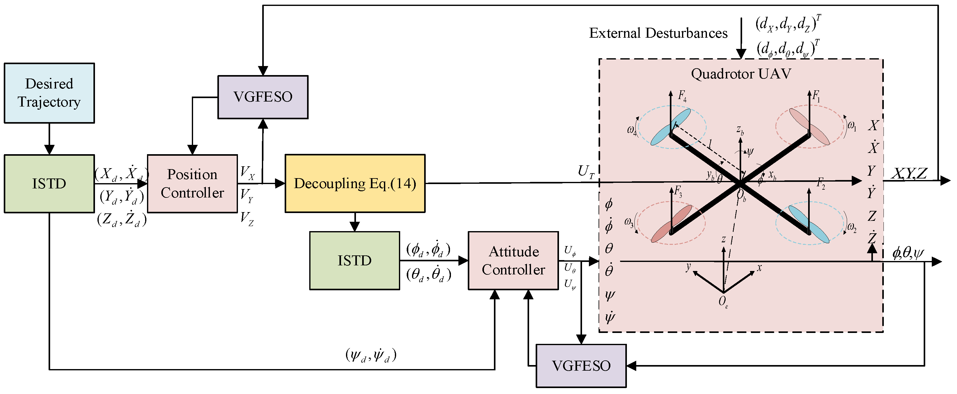
This section presents an improved ADRC scheme for quadrotor trajectory tracking using ISTD and VGFESO. The block diagram of the improved ADRC scheme is shown in Figure 2. The ISTD is proposed mainly to provide the transient profile of the reference signal and extract its derivative signal with improved transient and steady-state performance, while the VGFESO is proposed to estimate both the system state and the lumped disturbances.

3.1. Preliminaries

For simplicity, some notations are defined as x α = s i g n ( x ) | x | α , | x | α = [ | x 1 | α , | x 2 | α , , | x 3 | α ] T , s i g n ( · ) is a sign function with s i g n ( 0 ) = 0 .
Consider the following nonlinear system
x ˙ ( t ) = f ( x ( t ) ) , x ( 0 ) = x 0 , f ( 0 ) = 0 , x R n
where f : U R n is a continuous function in an open neighborhood U of the origin.
Lemma 1.
[19] On the convergence theorem of general tracking differentiator. Let f : n is a locally Lipschitz continuous function, f ( 0 , 0 ) = 0 . Suppose the equilibrium point ( 0 , 0 ) of the following system is globally asymptotically stable:
{ x ˙ 1 ( t ) = x 2 ( t ) , x 1 ( 0 ) = x 10 x ˙ 2 ( t ) = f ( x 1 ( t ) , x 2 ( t ) ) , x 2 ( 0 ) = x 20
where ( x 10 , x 20 ) is any given initial state. If v ( t ) is differentiable and satisfies A = s u p t [ 0 , ] | v ˙ ( t ) | < , then the solution of the following tracking differentiator
{ z ˙ 1 R ( t ) = z 2 R ( t ) , z 1 ( 0 ) = z 10 z ˙ 2 R ( t ) = R 2 f ( z 1 R ( t ) v ( t ) , z 2 R ( t ) R ) , z 2 ( 0 ) = z 20
is convergent in the case that: for any a > 0 , z 1 R is uniformly convergent to v ( t ) on [ a , ] as R , where ( z 10 , z 20 ) is any given initial value.
Lemma 2.
[42] Consider the nonlinear system in Equation (15), and suppose there exists a Lyapunov function denoting its initial value. The trajectory of the system is finite-time uniformly ultimately bounded stable within the region of Q 1 = { x | V ( x ) α 1 α 2 < β 2 ϵ 1 } , if V ˙ ( x ) β 1 V ( x ) α 1 + β 2 V ( x ) α 2 for 0 < α 1 < 1 , α 1 > α 2 , β 1 > 0 , β 2 > 0 , ϵ 1 ( 0 , β 1 ) . The settling time for the states reaching the stable residual set is subject to the constraint as T 1 V ( x 0 ) 1 α 1 ( β 2 ϵ 1 ) ( 1 α 1 ) .
Lemma 3.
[43] Consider the system in Equation (15), and suppose there exists a Lyapunov function V ( x ) defined on a neighborhood U R n of the origin, and V ˙ ( x ) + β 1 V ( x ) α 1 0 with x U \ { 0 } , 0 < α 1 < 1 , β 1 > 1 . Then the system is locally finite time stable, and T 1 1 β 1 ( 1 α 1 ) V ( x 0 ) 1 α 1 is the time needed to reach V ( x ) = 0 , with V ( x 0 ) denoting the initial value of the Lyapunov function V ( x ) .

3.2. ISTD Design and Analysis

To balance the tracking performance and parameter tuning of the tracking differentiator, the novel sigmoid function and sliding mode terminal attractor are adopted. Selecting an appropriate acceleration function is an efficient way to make the ISTD integrate both linear and nonlinear characteristics. The appropriate acceleration function is designed as follows:
i s i g ( x ) = 2 1 + e x 1
The function is mainly linear near the zero point. The approximate linear interval width of the function can be adjusted by introducing the parameter β . Then, the acceleration function is expressed as
i s i g ( β x ) = 2 1 + e β x 1
where β is a constant. The smaller the β is, the wider the linear interval width of Equation (19) is. Obviously, i s i g ( β x ) is a continuous odd function with boundaries
{ i s i g ( β x ) + i s i g ( β x ) = 0 lim x + i s i g ( β x ) = 1 , lim x i s i g ( β x ) = 1
The Taylor expansion with the remaining term of Equation (19) at zero point is expressed as
i s i g ( β x ) = i s i g ( β x ) | x = 0 + i s i g ( β x ) | x = 0 x + + R n ( x ) = β x β 3 4 x 3 + O ( x 3 )
where O ( x 3 ) denotes the higher order of x 3 .
Theorem 1.
With the proposed ISTD Γ 1 as follows.
{ x ˙ d , 1 r ( t ) = x d , 2 r ( t ) x ˙ d , 2 r ( t ) = R 2 { α | x d , 1 r ( t ) v ( t ) | σ i s i g ( β x ) ( x d , 1 r ( t ) v ( t ) ) + γ   i s i g ( x d , 2 r ( t ) R ) }
where σ = p / q , p < q , and p , q are odd numbers, α > 0 , γ > 0 , R > 0 . v ( t ) is the input signal, x d , 1 r ( t ) and x d , 2 r ( t ) are the tracking signal and differential signal of v ( t ) . Then, the system (22) is globally uniformly asymptotically stable in (0,0).
Proof. 
Step 1: Prove the following system Γ 0 is globally asymptotically stable with respect to the zero point.
{ z ˙ 1 = z 2 z ˙ 2 = α | z 1 | σ i s i g ( β z 1 ) γ   i s i g ( z 2 )
Consider the following Lyapunov function candidate:
V ( z 1 , z 2 ) = 0 z 1 α | ξ | σ i s i g ( β ξ ) d ξ + 1 2 z 2 2
As i s i g ( β ξ ) is a monotone increasing odd function, and the variable ξ is always the same sign as function i s i g ( β ξ ) , then
0 z 1 α | ξ | σ i s i g ( β ξ ) d ξ + 1 2 z 2 2 0
The equal sign is satisfied only when z 1 0 , z 2 0 . On the other hand, taking the derivative V ( z 1 , z 2 ) with regard to time yields
V ˙ ( z 1 , z 2 ) = α | z 1 | σ i s i g ( β z 1 ) z 1 ˙ + z 2 z 2 ˙ = α | z 1 | σ i s i g ( β z 1 ) z 2 + z 2 { α | z 1 | σ i s i g ( β z 1 ) γ   i s i g ( z 2 ) } = γ z 2   i s i g ( z 2 ) 0
The equal sign is satisfied only when z 2 = 0 . Therefore, Γ 0 is globally asymptotically stable with respect to the zero point.
Step 2: Proof system Γ 1 is the perturbation form of Γ 0 . Let τ = R t ,   y 1 ( τ ) = x d , 1 r ( t ) v ( t ) , y 2 ( τ ) = x d , 2 r ( t ) / R . y = [ y 1 , y 2 ] T is the solution to the system
d y ( τ ) d τ = F [ y ( τ ) ] + g ( τ )
where F [ y ( τ ) ] = [ y 2 ( τ ) α | y 1 ( τ ) | σ i s i g ( β y 1 ( τ ) ) a 1 i s i g ( y 2 ( τ ) ) ] T , g ( τ ) = [ v ˙ ( τ / R ) / R , 0 ] T . Replace t with τ to obtain y ˙ ( t ) = F [ y ( t ) ] + g ( t ) , and z = [ z 1 , z 2 ] T is the solution to the system z ˙ ( t ) = F [ z ( t ) ] . From Lemma 1, the signal v ( t ) is differentiable and satisfies A = s u p t [ 0 , ] | v ˙ ( t ) | < . Because v ˙ ( t ) has boundaries, when R , v ˙ ( τ / R ) / R 0 , the system Γ 0 and the system Γ 1 is equivalent and has global asymptotic stability. According to Lemma 1, the system Γ 1 is the perturbation form of Γ 0 , and the proposed ISTD is uniformly convergent. ☐

3.3. VGFESO Design and Stability Proof

The general adaptive ESO expression in [44] is designed as
{ x ^ ˙ 1 = x ^ 2 l 1 ( t ) ( x ^ 1 x 1 ) x ^ ˙ 2 = x ^ 3 l 2 ( t ) ( x ^ 1 x 1 ) + b 0 u x ^ ˙ 3 = l 3 ( t ) ( x ^ 1 x 1 )
where x ^ i ( i = 1 , 2 , 3 ) are the estimates of states x i , the total disturbance d is taken as an extended state x 3 . The estimation error is defined as E ˜ = [ e 1 , e 2 , e 3 ] T = [ x ^ 1 , x ^ 2 , x ^ 3 ] T [ x 1 , x 2 , x 3 ] T . A new ESO with variable gains is designed to estimate the disturbance with improved transient performance, and VGFESO is designed as
{ x ^ ˙ 1 = x ^ 2 l 1 ( t ) e 1 λ 1 x ^ ˙ 2 = x ^ 3 l 2 ( t ) e 1 λ 1 + b 0 u x ^ ˙ 3 = l 3 ( t ) e 1 λ 2
where 0.5 < λ 1 < 1 , λ 2 = 2 λ 1 1 . The varying gains are designed as l 1 ( t ) = L ( t ) , l 2 ( t ) = L ( t ) / 2 , l 3 ( t ) = L ( t ) , and L ( t ) is adapted according to the following rule
L ˙ ( t ) = { k | e 1 | i f   | e 1 | ϵ 0 o t h e r w i s e
where k > 0 is a constant, and ϵ > 0 is a constant that determines the accuracy of the observation errors. According to the following stability proof, L ( t ) is designed as 1 2 k | e 1 | 2   i f   | e 1 | ϵ , and ( 5 ( λ 1 + 1 ) ) 2 3 for otherwise, with k = 2 ( 5 ( λ 1 + 1 ) ϵ 3 ) 2 / 3 .
Theorem 2.
The observer errors of the VGFESO in Equation (29) converge to zero in a finite time when the adaptive gains l 1 ( t ) , l 2 ( t ) , l 3 ( t ) satisfy L ( 0 ) ( 48 5 ( λ 1 + 1 ) ) 2 / 3 .
Proof. 
The errors of the VGFESO can be expressed under the following form
{ e ˙ 1 = e 2 l 1 ( t ) e 1 λ 1 e ˙ 2 = e 3 l 2 ( t ) e 1 λ 1 e ˙ 3 = l 3 ( t ) e 1 λ 2 d ˙ ( t )
Assuming the total disturbance d is continuously differentiable and its differential d ˙ ( t ) is bounded with d ˙ ( t ) ρ . Define the following variation:
ζ = [ e 1 λ 1 , e 2 , e 3 ] T
Derivative ζ , yields to
ζ ˙ = [ λ 1 e 1 λ 1 1 ( e 2 l 1 ( t ) e 1 λ 1 ) e 3 l 2 ( t ) e 1 λ 1 l 3 ( t ) e 1 λ 2 d ˙ ( t ) ] = d i a g ( λ 1 e 1 λ 1 1 , 1 , e 1 λ 1 1 ) [ l 1 ( t ) 1 0 l 2 ( t ) 0 1 l 3 ( t ) 0 0 ] ζ + [ 0 0 1 ] d ˙ ( t ) Λ A ˜ ( t ) ζ + B d ˙ ( t ) A ( t ) ζ + B d ˙ ( t )
If l 1 ( t ) , l 2 ( t ) , l 3 ( t ) , λ are chosen properly at time t, and satisfy
{ λ 1 | e 1 | λ 1 1 l 1 ( t ) > 0 λ 1 | e 1 | λ 1 1 l 2 ( t ) > 0 λ 1 | e 1 | λ 2 l 3 ( t ) > 0 λ 1 l 1 ( t ) l 2 ( t ) l 3 ( t ) > 0
Then it can be considered that A is Hurwitz; there exists a positive definite matrix Q such that the equation has a solution P
A T P + P A = Q
where
P ( t ) = [ 2 l 1 ( t ) λ 1 + 1 + l 2 2 ( t ) + l 3 2 ( t ) l 2 ( t ) l 3 ( t ) l 2 ( t ) 2 0 l 3 ( t ) 0 2 ]
Consider the following Lyapunov candidate function
V ( ζ ) = 1 L ( t ) 2 ζ T P ( t ) ζ
Let χ represent the eigenvalue sequence, and the Equation (36) satisfying
χ m i n { P } ζ 2 2 V ( ζ ) χ m a x { P } ζ 2 2
The time derivative of V ( ζ ) can be expressed as
V ˙ ( ζ ) = d d t [ 1 L ( t ) 2 ζ T P ( t ) ζ ] = d d t [ ζ T 1 L ( t ) 2 P ( t ) ζ ] = ζ ˙ T 1 L ( t ) 2 P ( t ) ζ + ζ T d d t [ 1 L ( t ) 2 P ( t ) ] ζ + ζ T 1 L ( t ) 2 P ( t ) ζ ˙ = ζ T d d t [ 1 L ( t ) 2 P ( t ) ] ζ + 1 L ( t ) 2 [ ζ ˙ T P ( t ) ζ + ζ T P ( t ) ζ ˙ ]
Let V ˙ 1 = ζ T d d t [ 1 L ( t ) 2 P ( t ) ] ζ , V ˙ 2 = 1 L ( t ) 2 [ ζ ˙ T P ( t ) ζ + ζ T P ( t ) ζ ˙ ] . According to the definition of the varying gains in Equation (30), with the constant k = 0.5 , the first component V ˙ 1 can be expressed as follows:
V ˙ 1 = ζ T d d t [ 2 L 3 / 2 ( t ) λ 1 + 1 + 1 4 + 1 1 2 L 1 ( t ) L 1 ( t ) 1 2 L 1 ( t ) 2 L 2 ( t ) 0 L 1 ( t ) 0 2 L 2 ( t ) ] ζ = ζ T [ 3 L 5 / 2 ( t ) λ 1 + 1 1 2 L 2 ( t ) L 2 ( t ) 1 2 L 2 ( t ) 4 L 3 ( t ) 0 L 2 ( t ) 0 4 L 3 ( t ) ] L ˙ ζ ζ T Τ L ˙ ζ
where | T | = 48 λ 1 + 1 L 17 / 2 + 5 L 7 , L ˙ 0 . The determinant of T satisfying | T | 0 when | L ( 0 ) | ( 48 5 ( λ 1 + 1 ) ) 2 / 3 . Then, we have V ˙ 1 0 , V ˙ ( ζ ) V ˙ 2 . Replacing ζ ˙ in the expression in Equation (33), V ˙ 2 leads to
V ˙ 2 = 1 L ( t ) 2 [ ζ ˙ T P ( t ) ζ + ζ T P ( t ) ζ ˙ ] = 1 L ( t ) 2 { [ A ( t ) ζ + B d ˙ ] T P ( t ) ζ + ζ T P ( t ) [ A ( t ) ζ + B d ˙ ] } = 1 L ( t ) 2 { ζ T ( A T P + P A ) ζ + ( B d ˙ ) T P ζ + ζ T P B d ˙ } = 1 L ( t ) 2 { ζ T Q ζ + 2 d ˙ B T P ζ }
where B T P = [ l 3 ( t ) , 0 , 2 ] T , B T P 2 = l 3 2 + 4 . According to Equation (40), we can obtain
V ˙ 2 1 L ( t ) 2 { χ m i n { Q } ζ 2 2 2 d ˙ l 3 2 + 4 ζ 2 } 1 L ( t ) 2 { χ m i n { Q } ζ 2 2 d ˙ l 3 2 + 4 } ζ 2
Note that A T P + P A = Q , and Q is positive definite and nonsingular, then
χ m i n { Q } 2 χ m i n { A } χ m i n { P } 2 m i n { λ 1 e 1 λ 1 1 , 1 } χ m i n { A ˜ } χ m i n { P }
On the one hand, it can be obtained that ζ 2 > | e 1 | λ 1 , χ m i n { Q } 2 λ 1 | e 1 | λ 1 1 χ m i n { A ˜ } χ m i n { P } when | e 1 | > 1 , thus
χ m i n { Q } ζ 2 2 d ˙ l 3 2 + 4 2 λ 1 | e 1 | 2 λ 1 1 χ m i n { A ˜ } χ m i n { P } 2 d ˙ l 3 2 + 4 2 λ 1 χ m i n { A ˜ } χ m i n { P } 2 d ˙ l 3 2 + 4
V ˙ ( ζ ) 1 L ( t ) 2 { χ m i n { Q } ζ 2 2 d ˙ l 3 2 + 4 } ζ 2 ( 2 λ 1 χ m i n { A ˜ } χ m i n { P } 2 d ˙ l 3 2 + 4 ζ 2 ) V ( ζ ) χ m a x { P } 2 λ 1 χ m i n { A ˜ } χ m i n { P } 2 d ˙ l 3 2 + 4 ζ 2 χ m a x { P } V 1 / 2 ( ζ ) 0
According to Lemma 3, the error system can converge to the region | e 1 | 1 , and satisfy | ζ | 1 in finite time. On the other hand, | e 1 | λ 1 < ζ 2 < 1 χ m i n { Q } 2 λ 1 χ m i n { A ˜ } χ m i n { P } when | e 1 | 1 , thus
χ m i n { Q } ζ 2 2 d ˙ l 3 2 + 4 2 λ 1 | e 1 | λ 1 χ m i n { A ˜ } χ m i n { P } 2 d ˙ l 3 2 + 4
If the observer gains are correctly chosen, the error system can converge to the region in finite time, and the convergence time is
T f 2 κ 1 V 1 / 2 ( ζ 0 )
where κ 1 = 2 λ 1 χ m i n { A ˜ } χ m i n { P } 2 d ˙ l 3 2 + 4 ζ 2 χ m a x { P } . ☐

3.4. Nonlinear Controller Design

Consider the dynamic model in the form of the second-order plant as Equation (12) by denoting X 1 = P e , X 2 = P ˙ e , X 3 = Θ , X 4 = Θ ˙ .
{ X ˙ 1 = X 2 X ˙ 2 = ( B ¯ 1 U T + D ^ p ) / m ¯ X ˙ 3 = X 4 X ˙ 4 = J ¯ 1 ( τ + N ^ Θ )
The tracking errors are defined as e p = P d P e , e Θ = Θ d Θ . The desired trajectory and its differential signal are obtained by ISTD. Select the sliding mode surface σ 1 , σ 2 for the trajectory tracking control law as
{ σ 1 = c 1 e p + e ˙ p σ 2 = c 2 e Θ + e ˙ Θ
where c 1 , c 2 are positive numbers. Based on the dynamic model, the trajectory tracking controllers are obtained as
{ U T = m ¯ B ¯ 1 1 ( S 1 Z ^ p ) τ = J ¯   ( S 2 Z ^ Θ )
{ S 1 = k 1 σ 1 1 2 + η p η ˙ p = w 1 s i g n ( σ 1 )
{ S 2 = k 2 σ 2 1 2 + η Θ η ˙ Θ = w 2 s i g n ( σ 2 )
where Z ^ p and Z ^ Θ are the estimation of the lumped disturbances by the previous VGFESO, k 1 , k 2 , w 1 , w 2 are positive numbers. Substituting (49), (51) into (48), σ ˙ 2 leads to
σ ˙ 2 = c 2 e ˙ Θ + e ¨ Θ = c 2 e ˙ Θ + Θ ¨ d J ¯ 1 ( τ + N ^ Θ ) = c 2 e ˙ Θ + Θ ¨ d + S 2 E ˜
Substituting (48), (49), (51) and (52), a sliding mode system is obtained as
{ σ ˙ 2 = k 2 σ 2 1 2 + η Θ + c 2 e ˙ Θ + Θ ¨ d E ˜ η ˙ Θ = w 2 s i g n ( σ 2 )
According to [39], the following assumptions here: the estimated error of disturbance E ˜ is bounded. There exists an unknown constant μ 1 > 0 , which is satisfied with μ 1 σ 2 1 2 > 2 | c 2 e ˙ Θ + Θ ¨ d | . Moreover, there exists an unknown constant μ 2 > 0 , which is satisfied with μ 2 > | E ˜ ˙ | . Let c 2 e ˙ Θ + Θ ¨ d = b 1 σ 2 1 2 with | b 1 | < μ 1 , and | E ˜ ˙ | = b 2 s i g n ( σ 2 ) / 2 with | b 2 | < μ 2 . Setting η ¯ Θ = η Θ + E ˜ , the sliding model system (53) is transferred as follows:
{ σ ˙ 2 = k 2 σ 2 1 2 + η ¯ Θ + b 1 σ 2 1 2 η ¯ Θ ˙ = w 2 s i g n ( σ 2 ) 1 2 b 2 s i g n ( σ 2 )
Theorem 3.
The continuous super-twisting sliding mode surface σ ( t ) converges to a small field in the finite time.
Proof. 
Take the attitude subsystem, for example, and consider the following Lyapunov candidate function:
V 3 ( t ) = Ξ T M Ξ
where Ξ T = [ ξ 1 , η ¯ Θ ] = [ σ 2 1 2 , η ¯ Θ ] , M = [ m 11 m 12 m 21 m 22 ] = [ ϱ + 4 ϵ 2 2 ϵ 2 ϵ 1 ] .
Derivative Ξ , yields to
Ξ ˙ = [ 1 2 σ 2 1 2 { k 2 σ 2 1 2 + η ¯ Θ + b 1 σ 2 1 2 } w 2 s i g n ( σ 2 ) 1 2 b 2 s i g n ( σ 2 ) ] = [ 1 2 | ξ 1 | { ( k 2 + b 1 ) ξ 1 + η ¯ Θ } ( w 2 1 2 b 2 ) ξ 1 2 | ξ 1 | ] = 1 2 | ξ 1 | [ k 2 + b 1 1 w 2 1 2 b 2 0 ] Ξ   ξ 1 ˙ H Ξ
Then V 3 ( t ) is continuous, and the derivative of the Lyapunov function is presented as
V 3 ˙ ( t ) = ξ 1 ˙ Ξ T ( H T Μ + M H ) Ξ = ξ 1 ˙ Ξ T N Ξ
where
N = [ 2 ( k 2 b 1 ) ( ϱ + 4 ϵ 2 ) 4 ϵ ( w 2 + 1 2 b 2 ) ( ϱ + 4 ϵ 2 ) 2 ϵ ( k 2 b 1 ) + ( w 2 + 1 2 b 2 ) ( ϱ + 4 ϵ 2 ) 2 ϵ ( k 2 b 1 ) + ( w 2 + 1 2 b 2 ) 4 ϵ ]
The symmetric matrix N is positive definite with the minimal eigenvalue χ m i n { N } 2 ϵ ¯ if appropriate parameters are selected. Since χ m i n { M } Ξ 2 2 Ξ T M Ξ χ m a x { M } Ξ 2 2 , where Ξ 2 2 = ξ 1 2 + η ¯ Θ 2 is the Euclidean norm of Ξ , and
ξ 1 Ξ 2 V 3 1 / 2 ( t ) χ m i n 1 / 2 { M }
We can conclude that
V 3 ˙ ( t ) 1 2 | σ 2 | 1 2 2 ϵ ¯ Ξ T Ξ ϵ ¯ χ m i n 1 / 2 { M } χ m a x { M } V 3 1 / 2 ( t )
It is concluded that σ ( t ) converges to a small field in the finite time according to Lemma 3. ☐

4. Results and Discussion

To testify the effectiveness of the proposed sigmoid tracking differentiator and variable gain finite-time extended state observer, numerical simulations are carried out for a UAV with trajectory tracking control.

4.1. Effect of the ISTD Parameter

The sweep tests based on the least square method could obtain the Bode diagram of the ISTD more accurately. The relationship between parameters and convergence speed, tracking accuracy, and noise suppression capability can be clarified through frequency analysis, which is conducive to the parameter tuning of ISTD. Let x d , 1 r ( t ) v ( t ) = A s i n ( ω t ) , and then the nonlinear function is defined as N ( A ) = ( B 1 + j A 1 ) / A , Since f 1 = a 0 | x d , 1 r ( t ) v ( t ) | q t s i g ( β ( x d , 1 r ( t ) v ( t ) ) ) and f 2 = a 1 t s i g ( x d , 2 r ( t ) / R ) are both odd functions, then the coefficients of their descriptive functions are expressed as
A 1 = 0 , B 1 = 0 2 π a 0 | A s i n ( ω t ) | q t s i g ( β A s i n ( ω t ) s i n ( ω t ) d ( ω t ) / π
A 2 = 0 , B 2 = 0 2 π a 1 t s i g ( β A s i n ( ω t ) s i n ( ω t ) d ( ω t ) / π .
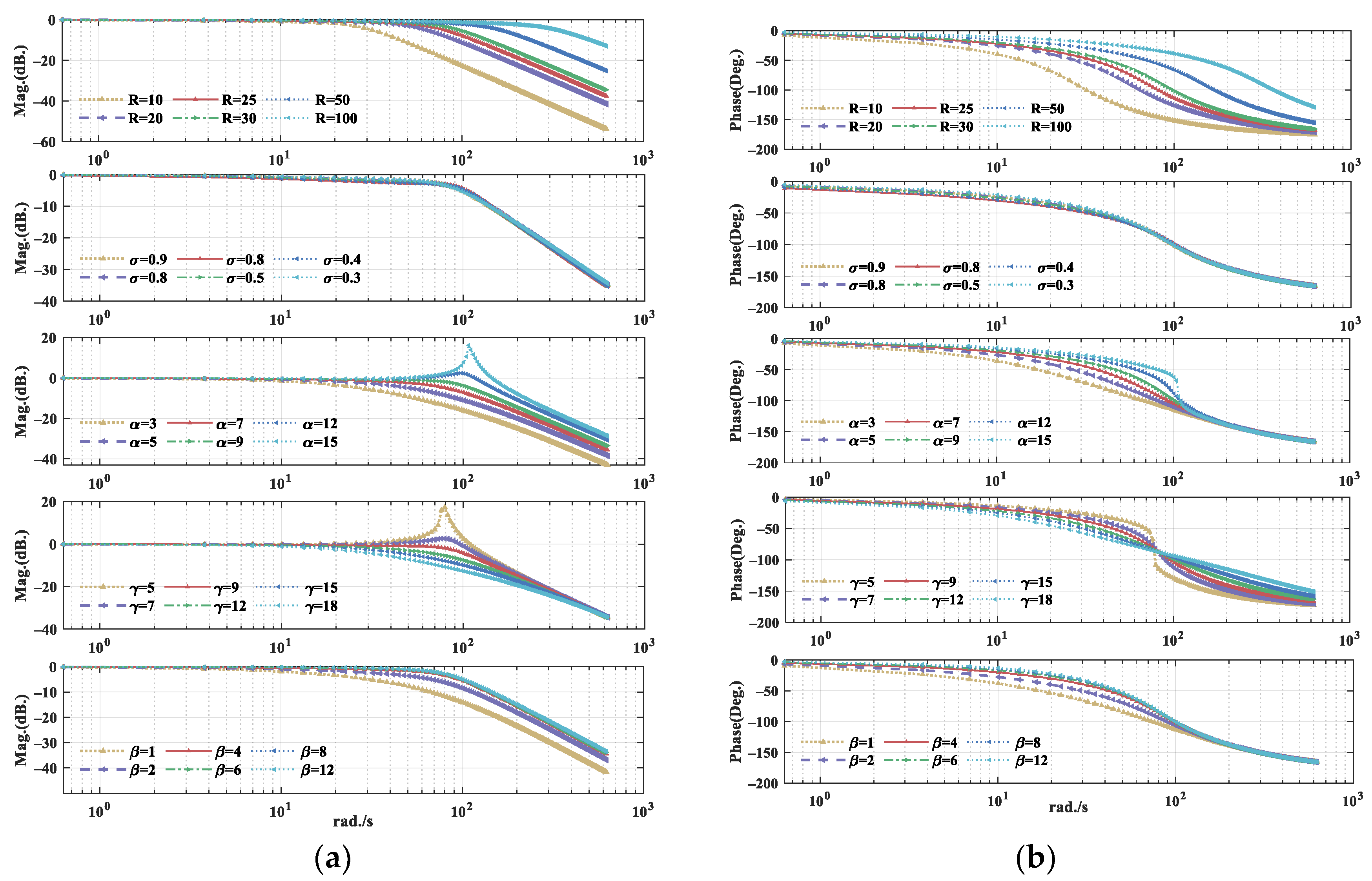
Then the transfer function between the input signal v ( t ) and its tracking element x d , 1 r ( t ) is given by G ( s ) = R 2 N 1 ( A ) / ( s 2 + N 2 ( A ) s + R 2 N 1 ( A ) ) . One of the parameters R ,   σ ,   α ,   β ,   γ is chosen as a change parameter, and the other parameters remain unchanged. Five simulations are carried out to test the influence of different parameters on the performance of the ISTD. The Bode diagrams are plotted in Figure 3. The effect of the ISTD parameter could be analyzed, and the guide for the parameter selection is given below.
Effect of acceleration factor R ,   α : to analyze the effect of acceleration factor on the frequency performance of ISTD, first we choose the parameter as σ = 0.9 ,   β = 10 ,   γ = 10 with different values of R ,   α , i.e., R = 10 ,   20 ,   25 ,   30 ,   50 ,   100 , and α = 3 ,   5 ,   7 ,   9 ,   12 ,   15 . The phase-frequency characteristic has a very small phase shift below the cutoff frequency, but near the corner frequency, the phase shift quickly drops to −180°. It can be concluded from the Bode diagrams that the bandwidth frequency increases when R ,   α increase. The larger the bandwidth, the faster the convergence rate and better high-frequency range tracking performance. Simultaneously, more high-frequency noise will pass through, which results in worse filtering performance of ISTD. A balance on the selection of R ,   α should be made between the tracking performance and filtering ability of ISTD.
Effect of acceleration factor σ ,   γ : we choose the parameter as R = 30 ,   α = 8 ,   β = 10 with different values of σ , γ , i.e., σ = 0.9 ,   0.8 ,   0.7 ,   0.5 ,   0.4 ,   0.3 , and γ = 5 ,   7 ,   9 ,   12 ,   15 ,   18 . It can be concluded from the Bode diagrams that the filtering ability is enhanced when σ ,   γ increase, but the bandwidth is reduced and the time delay is increased. The designed parameter is for adjusting the differential performance and σ for suppressing high-frequency noise.
Effect of acceleration factor β : we choose the parameter as R = 30 , σ = 0.9 , α = 8 , γ = 10 with different values of β , i.e., β = 1 ,   2 ,   4 ,   6 ,   8 ,   12 . It can be concluded from the Bode diagrams that the tracking accuracy is enhanced when β increases. The designed parameter is for improving the tracking accuracy to a certain extent.
The parameter tuning rules could be derived. Firstly, select the appropriate R to ensure the overall performance, generally R = 30 . Next, choose a larger σ to reduce the sensitivity to noise. Next is fine adjustment α and β to obtain well tracking and differential effects. Finally, the parameters of the proposed ISTD are selected as R = 30 ,   σ = 0.9 ,   α = 8 ,   β = 10 ,   γ = 10 .

4.2. Compared Simulation Results of Different TDs

In this section, the compared simulations are carried out to verify the filtering and tracking performances of the proposed ISTD with another traditional tracking differentiator: TD [17] and STD [20].
The TD is given by:
{ x ˙ d , 1 r ( t ) = x d , 2 r ( t ) x ˙ d , 2 r ( t ) = R s i g n ( x d , 1 r ( t ) x d , 1 ( t ) + x d , 2 r ( t ) · | x d , 2 r ( t ) | 2 R )
The STD is given by
{ x ˙ d , 1 r ( t ) = x d , 2 r ( t ) x ˙ d , 2 r ( t ) = R 2 [ s i g ( x d , 1 r ( t ) x d , 1 ( t ) ; μ 0 , μ 1 ) + s i g ( x d , 2 r ( t ) / R ; μ 2 , μ 3 )
where s i g ( x d , 1 r ( t ) x d , 1 ( t ) ;   μ 0 , μ 1 ) = μ 0 ( 1 + e μ 1 ( x d , 1 r ( t ) x d , 1 ( t ) ) ) 1 0.5 μ 0 , s i g ( x d , 2 r ( t ) / r 0 ; μ 2 , μ 3 ) = μ 2 ( 1 + e μ 3 ( x d , 2 r ( t ) / r 0 ) ) 1 0.5 μ 2 . The parameters of TD are R = 30 ;   h = 0.001 . The parameters of STD are R = 30 ;   μ 0 = 5 ;   μ 1 = 5 ; μ 2 = 2 ;   μ 3 = 2 .
The desired tracking signal is a square-wave signal containing a Gaussian white noise with zero mean and covariance of 0.01. We choose the parameter as σ = 0.9 ,   α = 8 ,   β = 10 ,   γ = 10 with different values of R , i.e., R = 5 ,   10 ,   15 ,   20 , 30 ,   50 . It can be seen from Figure 4 that the parameter R in ISTD is a basic acceleration factor. With the rise of R, the tracking speed of ISTD is accelerated. But after R > 20 , the attenuation speed is decelerated, and the filtering ability of the differential signal is weakened. The larger the R is, the faster the tracking rate, but the filtering ability will become worse, which is consistent with the previous frequency analysis. The compared filtering and tracking performances are shown in Figure 5. The TDs use optimal parameters with R = 30 for tracking performance comparisons based on references. It can be seen that TD has slower tracking convergence, and STD has a large amplitude overshoot after 15 s. On the contrary, the proposed ISTD could rapidly approach the reference signals with little overshoot and correctly track the reference signal.

4.3. Comperated Performance with Different ESOs

The cooperated simulations are carried out to verify the effectiveness of the proposed VGFESO with LESO [22], FTESO [23], and improved FXESO [24].
The LESO is given by
{ z 1 = z 2 + v 1 ( z 1 x 1 ) z 2 = z 3 + v 2 ( z 1 x 1 ) + b u z 3 = v 3 ( z 1 x 1 )
The FTESO is given by
{ z 1 = z 2 κ 1 s i g ( a + 1 ) / 2 ( z 1 x 1 ) z 2 = z 2 κ 2 s i g ( a + 1 ) / 2 ( z 1 x 1 ) + b u z 3 = κ 3 s i g a ( z 1 x 1 )
The FXESO is given by
{ z 1 = z 2 + μ 1 s i g α ( z 1 x 1 ) + μ 1 s i g β ( z 1 x 1 ) z 2 = z 2 + μ 2 s i g 2 α 1 ( z 1 x 1 ) + μ 2 s i g 2 β 1 ( z 1 x 1 ) + b u z 3 = μ 3 s i g 3 α 2 ( z 1 x 1 ) + μ 3 s i g 3 β 2 ( z 1 x 1 ) + γ s i g n ( z 1 x 1 )
Take the attitude control subsystem, for example, to verify the performance of the proposed VGFESO. The state of desired attitude Θ and the lumped disturbances N Θ is given by
Θ : { ϕ = 2 sin ( π / 8 · t ) θ = 3 sin ( π / 6 · t + π / 12 ) ψ = π / 3 ,     N Θ : { n ϕ = 0.3 sin ( 0.5 t + π / 3 ) n θ = 0.4 cos ( 0.5 t + π / 6 ) + 0.1 n ψ = 0.3 cos ( 0.5 t + π / 4 ) + 0.2
According to the previous design and stability of VGFESO, the parameter should meet the following conditions: 0.5 < λ 1 < 1 ,   λ 2 = 2 λ 1 1 . The varying gains are designed as l 1 ( t ) = L ( t ) ,   l 2 ( t ) = L ( t ) / 2 ,   l 3 ( t ) = L ( t ) , and L ( t ) follow the adaptive rule in Equation (30). The initial conditions of four ESOs are given as zero, and all the parameters are listed in Table 1.
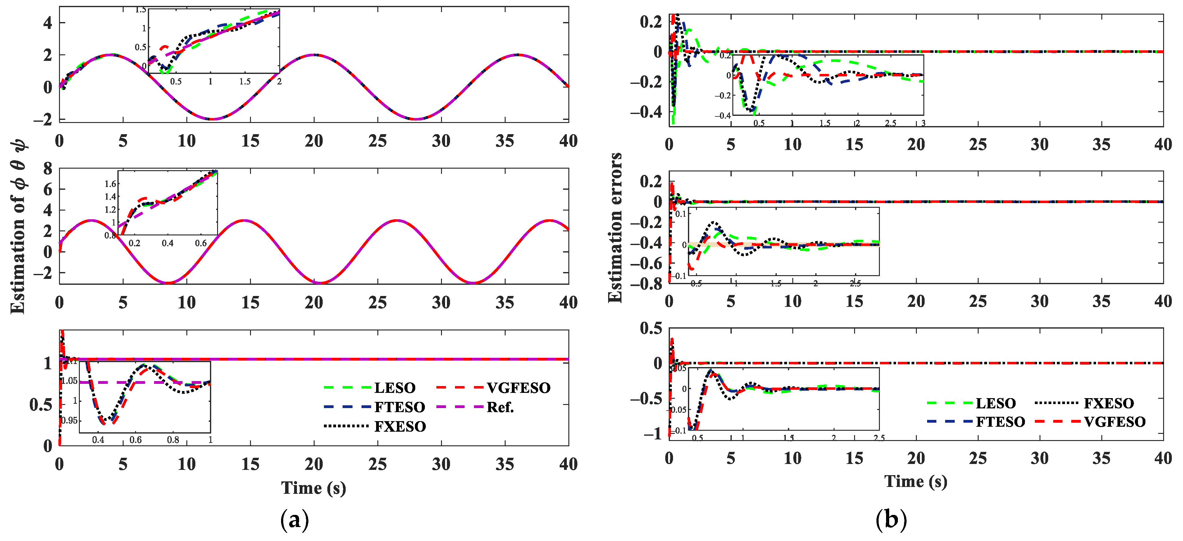
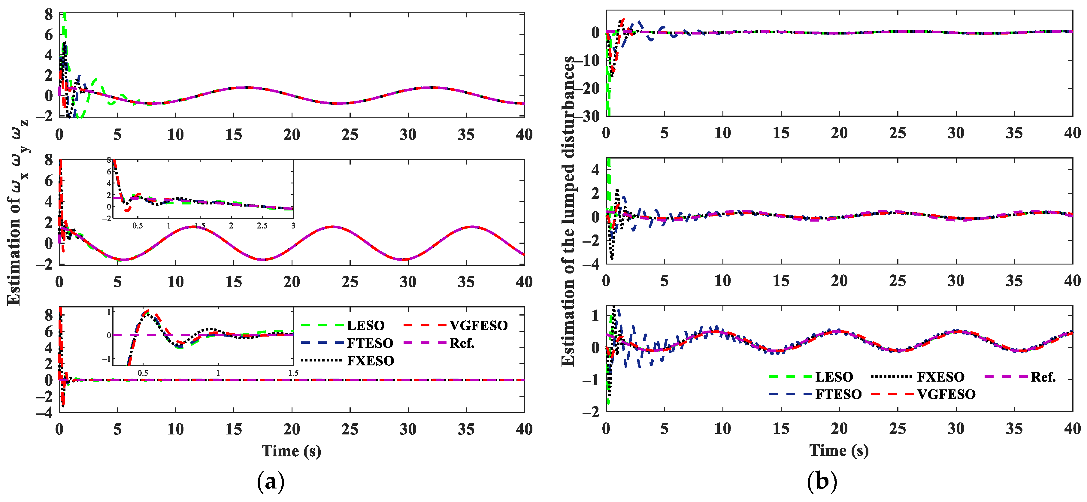
The attitude estimation ϕ ^ ,   θ ^ ,   ψ ^ of four ESOs, and the estimation errors are shown in Figure 6. The setting times of the ϕ ^ , θ ^ , ψ ^ estimation are 2.630 s, 1.845 s, and 1.405 s for VGFESO, while they are 3.020 s, 1.935 s, and 1.580 s for FXESO, 3.120 s, 2.430 s, and 1.725 s for FTESO, and 12.010 s, 6.105 s, and 5.515 s for LESO. The setting time of four ESOs is demonstrated in Table 2. It can be concluded that the setting time of the proposed VGFESO is the shortest. Figure 7 presents the differential estimation of ϕ ˙ ^ ,   θ ˙ ^ ,   ψ ˙ ^ , and the lumped disturbance estimation n ^ ϕ ,   n ^ θ ,   n ^ ψ , respectively. The performance of VGFESO is the best due to the fastest convergence time and minimal overshoot.

4.4. Trajectory Tracking Control Results

To verify the quadrotor trajectory tracking performance of proposed improved ADRC scheme, it is compared with the following ADRC [34] RANFTSMC [7] and ILSMC [30]. Quality of quadrotor m ¯ = 1.65   kg , gravitational acceleration g = 9.81 m/s2, length between the center of the quadrotor and the rotor l = 0.225 m, rotational inertia J ¯ = [ J ¯ x , J ¯ y , J ¯ z ] = [ 0.1782 ,   0.1782 ,   0.03191 ]   kg · m 2 , motor propeller moment of inertia Jr = 0.000099 kg·m2, the coefficient of air resistance [kx, ky, kz] = [0.005567, 0.005567, 0.005567]. As the proposed feedback control law is relatively simplified and the parameters of the super-twisting algorithm in [45,46] have given significant reference value, the designed controller parameters are shown in Table 3. At the same time, considering the actuator saturation problem, the maximum saturation is set in the controller design.
The desired position P e and the lumped disturbances D p are given by
P e : { x = 0.5 cos ( π / 10 · t ) y = 0.5 sin ( π / 10 · t ) z = 0.8 + t / 20 ,     D p : { d x = 0.2 sin ( 0.2 t ) + 0.1 cos ( 0.3 t ) d y = 0.4 cos ( 0.5 t ) + 0.2 d z = 0.2 cos ( 0.1 t + π / 4 ) + 0.1
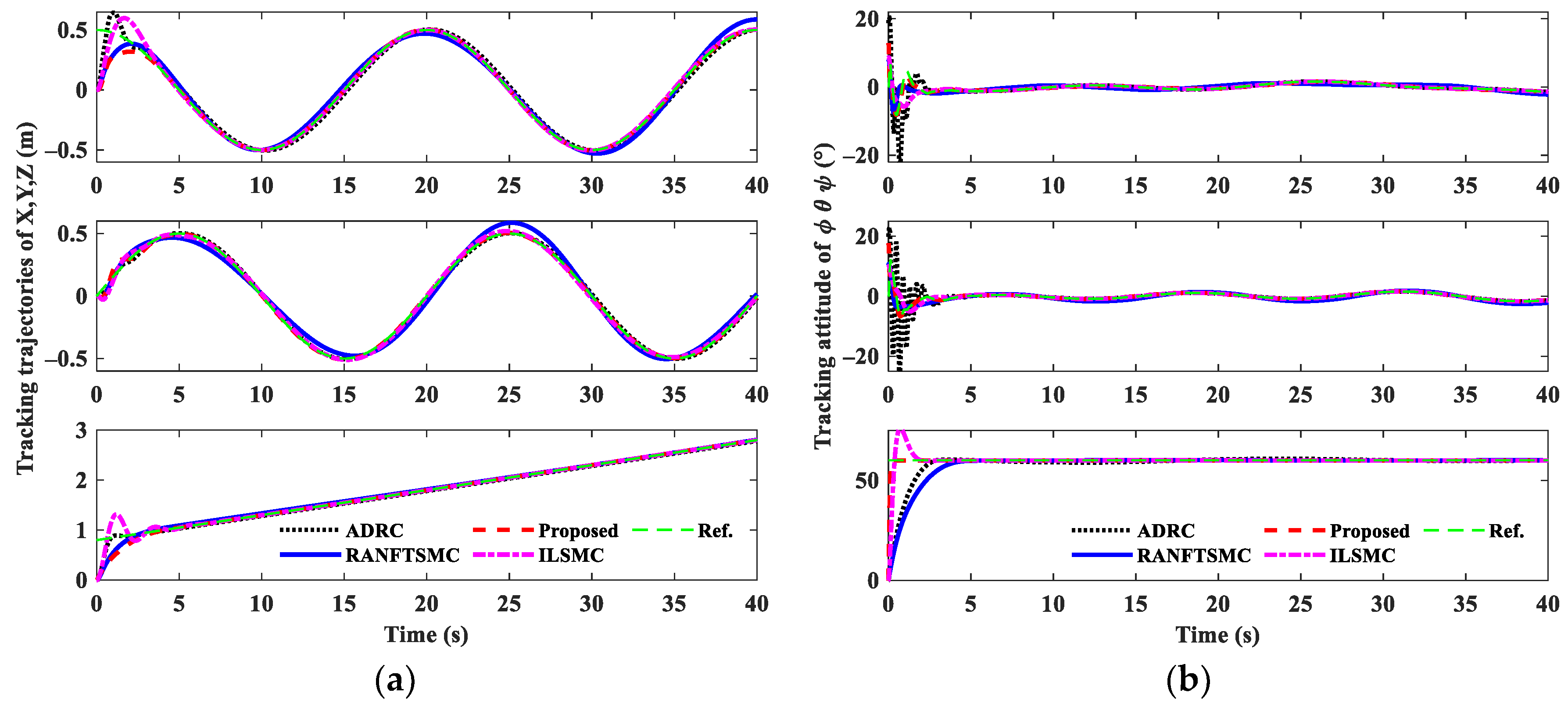
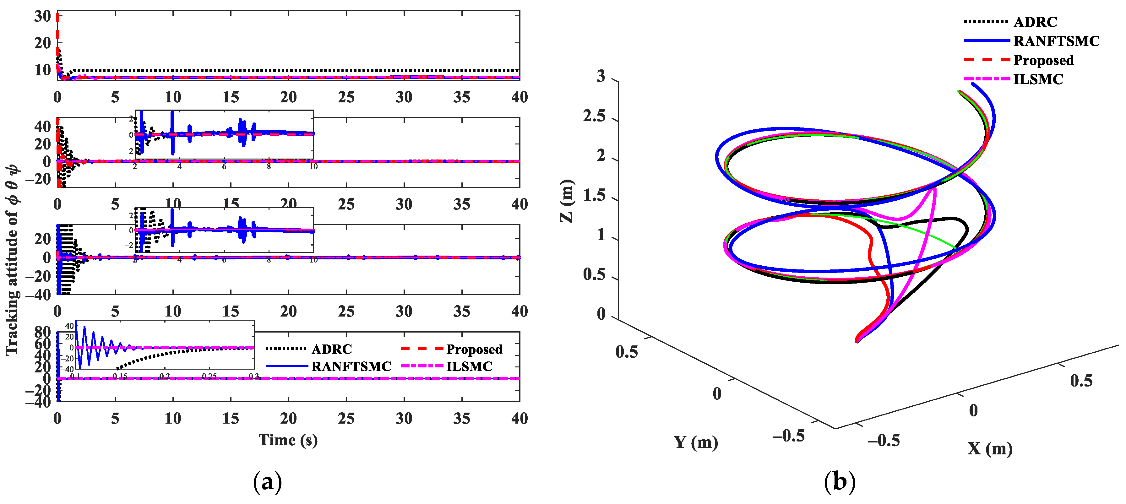
The lumped disturbances N Θ and attitude ψ are the same as previously given, and attitude ϕ ,   θ are calculated by nonlinear decoupling Equation (14). Figure 8 presents the position tracking performance of four controllers, and attitude tracking performance, respectively. It is obtained that the proposed controller could follow the reference trajectory quickly and with smaller overshooting, while ADRC has large oscillation errors at the initial moment. The quadrotor inputs [ u T ,   τ ϕ ,   τ θ ,   τ ψ ] T are shown in Figure 9a. Obviously, the inputs of the proposed controller are more stable. At the same time, ADRC requires a larger amount of control at the initial moment, and RANFTSMC has an oscillating control signal, which is detrimental to the life of the actuator. The 3D trajectory tracking performance comparison is demonstrated in Figure 9b. This will more clearly demonstrate the superior tracking control performance of the proposed controller. To effectively evaluate the performance of four quadrotor trajectory tracking controllers, Integral Absolute Errors (IAE) are used. The indicator IAE is defined as [47]
IAE = t i t f e i d t
The comparison of trajectory tracking performance is listed in Table 4. It can be seen that the IAE of the proposed controller is reduced from 2.64 to 0.91, which fully illustrates the anti-disturbance capability and high-precision tracking control accuracy of the proposed controller when compared with ADRC, RANFTSMC and ILSMC.

5. Conclusions

To solve the problem of trajectory tracking under lumped disturbances, a novel control scheme is proposed. The designed controller combines the super-twisting sliding model controller with ISTD and VGFESO. The ISTD is used for tracking the differential signal, while VGESO is used to estimate the lumped interference, and the estimation error converges to zero in finite time. The performance of the proposed controller is validated on the quadrotor UAV system, and the results are compared with the ADRC and RANFTSMC. Simulation results show that the convergence time of the proposed VGFESO is the shortest, and the IAE of improved ADRC is reduced from 2.64 to 0.91, which fully illustrates the anti-disturbance capability of the proposed controller. In the future, more modifications will be dedicated to extending the proposed scheme to output feedback-based flight controllers, and the effectiveness of the proposed controller will be validated through real-time flight experiments on a quadrotor UAV.

Author Contributions

W.Z.: writing the initial draft, editing and reviewing, methodology, simulation programming, and experiments. L.W.: writing the initial draft, conceptualization, and revisions. Y.R. and Y.L. revised the draft. All authors have read and agreed to the published version of the manuscript.

Funding

The research was funded by Primary Research & Development Plan of Jiangsu Province (BE2022389), Jiangsu Province Agricultural Science and Technology Independent Innovation Fund Project [CX(22)3091].

Institutional Review Board Statement

The study was conducted in accordance with the Declaration of Helsinki.

Informed Consent Statement

Not applicable.

Data Availability Statement

The data and code are considered intellectual property of the NNSFC project and are therefore not publicly available.

Conflicts of Interest

The authors declare no conflict of interest.

References

  1. Hassanalian, M.; Abdelkefi, A. Classifications, applications, and design challenges of drones: A review. Prog. Aeosp. Sci. 2017, 91, 99–131. [Google Scholar] [CrossRef]
  2. Mahmud, I.; Cho, Y. Detection avoidance and priority-aware target tracking for UAV group reconnaissance operations. J. Intell. Robot. Syst. 2018, 92, 381–392. [Google Scholar] [CrossRef]
  3. Zhao, N.; Lu, W.; Sheng, M.; Chen, Y.; Tang, J.; Yu, F.R.; Wong, K.-K. UAV-assisted emergency networks in disasters. IEEE Wirel. Commun. 2019, 26, 45–51. [Google Scholar] [CrossRef] [Green Version]
  4. Mehndiratta, M.; Kayacan, E. A constrained instantaneous learning approach for aerial package delivery robots: Onboard implementation and experimental results. Auton. Robot. 2019, 43, 2209–2228. [Google Scholar] [CrossRef]
  5. Hao, M.; Zhao, W.; Qin, L.; Mao, P.; Qiu, X.; Xu, L.; Xiong, Y.J.; Ran, Y.; Qiu, G. A methodology to determine the optimal quadrat size for desert vegetation surveying based on unmanned aerial vehicle (UAV) RGB photography. Int. J. Remote Sens. 2020, 42, 84–105. [Google Scholar] [CrossRef]
  6. Zang, Y.; Zang, Y.; Zhou, Z.; Gu, X.; Jiang, R.; Kong, L.; He, X.; Luo, X.; Lan, Y. Design and anti-sway performance testing of pesticide tanks in spraying UAVs. Int. J. Agric. Biol. Eng. 2019, 12, 10–16. [Google Scholar] [CrossRef] [Green Version]
  7. Labbadi, M.; Cherkaoui, M. Robust adaptive nonsingular fast terminal sliding-mode tracking control for an uncertain quadrotor UAV subjected to disturbances. ISA Trans. 2020, 99, 290–304. [Google Scholar] [CrossRef]
  8. Li, B.; Gong, W.; Yang, Y.; Xiao, B.; Ran, D. Appointed Fixed Time Observer-Based Sliding Mode Control for a Quadrotor UAV Under External Disturbances. IEEE Trans. Aerosp. Electron. Syst. 2022, 58, 290–303. [Google Scholar] [CrossRef]
  9. Miranda-Colorado, R.; Aguilar, L. Robust PID control of quadrotors with power reduction analysis. ISA Trans. 2020, 98, 47–62. [Google Scholar] [CrossRef]
  10. Wang, S.; Polyakov, A.; Zheng, G. Quadrotor stabilization under time and space constraints using implicit PID controller. J. Frankl. Inst.-Eng. Appl. Math. 2022, 359, 1505–1530. [Google Scholar] [CrossRef]
  11. Saif, A.; Aliyu, A.; Al Dhaifallah, M.; Elshafei, M. Decentralized backstepping control of a quadrotor with tilted-rotor under wind gusts. Int. J. Control Autom. Syst. 2018, 16, 2458–2472. [Google Scholar] [CrossRef]
  12. Liu, J.; Gai, W.; Zhang, J.; Li, Y. Nonlinear adaptive backstepping with ESO for the quadrotor trajectory tracking control in the multiple disturbances. Int. J. Control Autom. Syst. 2019, 17, 2754–2768. [Google Scholar] [CrossRef]
  13. Ijaz, S.; Chen, F.; Hamayun, M. A new actuator fault-tolerant control for Lipschitz nonlinear system using adaptive sliding mode control strategy. Int. J. Robust Nonlinear Control 2021, 31, 2305–2333. [Google Scholar] [CrossRef]
  14. Jiang, T.; Song, T.; Lin, D. Integral sliding mode based control for quadrotors with disturbances: Simulations and experiments. Int. J. Control Autom. Syst. 2019, 17, 1987–1998. [Google Scholar] [CrossRef]
  15. Najm, A.; Ibraheem, I. Altitude and Attitude Stabilization of UAV Quadrotor System using Improved Active Disturbance Rejection Control. Arab. J. Sci. Eng. 2020, 45, 1985–1999. [Google Scholar] [CrossRef]
  16. Han, J. Auto disturbances rejection controller and its applications. Control Decis. 1998, 13, 19–23. [Google Scholar]
  17. Han, J. From PID to Active disturbance rejection control. IEEE Trans. Ind. Electron. 2009, 56, 900–906. [Google Scholar] [CrossRef]
  18. Gao, Z. Scaling and bandwidth-parameterization based controller tuning. In Proceedings of the American Control Conference 2003, Denver, CO, USA, 4–6 June 2003; pp. 4989–4996. [Google Scholar]
  19. Guo, B.; Zhao, Z. On Convergence of the nonlinear active disturbance rejection control for MIMO systems. SIAM J. Control Optim. 2013, 51, 1727–1757. [Google Scholar] [CrossRef]
  20. Shao, X.; Liu, J.; Wang, H. Robust backstepping output feedback trajectory tracking for quadrotors via extended state observer and sigmoid tracking differentiator. Mech. Syst. Signal Process. 2018, 104, 631–647. [Google Scholar] [CrossRef]
  21. Mo, H.; Farid, G. Nonlinear and adaptive intelligent control techniques for quadrotor UAV—A survey. Asian J. Control 2018, 21, 989–1008. [Google Scholar] [CrossRef]
  22. Zhang, Q.; Fan, Y.; Mao, C. A gain design method for a linear extended state observer to improve robustness of deadbeat control. IEEE Trans. Energy Convers. 2020, 35, 2231–2239. [Google Scholar] [CrossRef]
  23. Zhao, L.; Zhang, B.; Yang, H.; Wang, Y. Finite-time tracking control for pneumatic servo system via extended state observer. IET Control Theory Appl. 2017, 11, 2808–2816. [Google Scholar] [CrossRef]
  24. Zhang, J.; Yu, S.; Yan, Y. Fixed-time extended state observer-based trajectory tracking and point stabilization control for marine surface vessels with uncertainties and disturbances. Ocean. Eng. 2019, 186, 106109. [Google Scholar] [CrossRef]
  25. Zhao, Z.; Guo, B. On active disturbance rejection control for nonlinear systems using time-varying gain. Eur. J. Control 2015, 23, 62–70. [Google Scholar] [CrossRef]
  26. Tsai, S.; Chang, Y.; Lin, H.; Chang, L. Design and Implementation of Integral Backstepping Sliding Mode Control for Quadrotor Trajectory Tracking. Processes 2021, 9, 1951. [Google Scholar] [CrossRef]
  27. Wang, H.; Li, N.; Wang, Y.; Su, B. Backstepping sliding mode trajectory tracking via extended state observer for quadrotors with wind disturbance. Int. J. Control Autom. Syst. 2021, 19, 3273–3284. [Google Scholar] [CrossRef]
  28. Zhao, J.; Ding, X.; Jiang, B.; Jiang, G.; Xie, F. A novel control strategy for quadrotors with variable mass and external disturbance. Int. J. Robust Nonlinear Control 2021, 31, 8605–8631. [Google Scholar] [CrossRef]
  29. Labbadi, M.; Cherkaoui, M. Robust adaptive backstepping fast terminal sliding mode controller for uncertain quadrotor UAV. Aerosp. Sci. Technol. 2019, 93, 105306. [Google Scholar] [CrossRef]
  30. Fu, X.; He, J. Robust Adaptive Sliding Mode Control Based on Iterative Learning for Quadrotor UAV. IETE J. Res. 2021. [Google Scholar] [CrossRef]
  31. Allahverdy, D.; Fakharian, A.; Menhaj, M.B. Back-Stepping Integral Sliding Mode Control with Iterative Learning Control Algorithm for Quadrotor UAVs. J. Electr. Eng. Technol. 2019, 14, 2539–2547. [Google Scholar] [CrossRef]
  32. Mofid, O.; Mobayen, S.; Wong, W.K. Adaptive terminal sliding mode control for attitude and position tracking control of quadrotor UAVs in the existence of external disturbance. IEEE Access 2020, 9, 3428–3440. [Google Scholar] [CrossRef]
  33. Wang, B.; Zhang, Y.; Zhang, W. Integrated path planning and trajectory tracking control for quadrotor UAVs with obstacle avoidance in the presence of environmental and systematic uncertainties: Theory and experiment. Aerosp. Sci. Technol. 2022, 120, 107277. [Google Scholar] [CrossRef]
  34. Elmokadem, T.; Savkin, A.V. A method for autonomous collision-free navigation of a quadrotor UAV in unknown tunnel-like environments. Robotica 2022, 40, 835–861. [Google Scholar] [CrossRef]
  35. Zhao, G.; Chen, G.; Chen, J.; Hua, C. Finite-time control for image-based visual servoing of a quadrotor using nonsingular fast terminal siding mode. Int. J. Control Autom. Syst. 2020, 18, 2337–2348. [Google Scholar] [CrossRef]
  36. Eliker, K.; Zhang, W. Finite-time adaptive integral backstepping fast terminal sliding mode control application on quadrotor UAV. Int. J. Control. Autom. Syst. 2020, 18, 415–430. [Google Scholar] [CrossRef]
  37. Nie, Z.; Zhang, B.; Wang, Q.; Liu, R.; Luo, J. Adaptive active disturbance rejection control guaranteeing uniformly ultimate boundedness and simplicity. Int. J. Robust Nonlinear Control 2020, 30, 7278–7294. [Google Scholar] [CrossRef]
  38. Feng, H.; Guo, B. A new active disturbance rejection control to output feedback stabilization for a one-dimensional anti-stable wave equation with disturbance. IEEE Trans. Autom. Control. 2017, 62, 3774–3787. [Google Scholar] [CrossRef]
  39. Zhang, Y.; Chen, Z.; Zhang, X.; Sun, Q.; Sun, M. A novel control scheme for quadrotor UAV based upon active disturbance rejection control. Aerosp. Sci. Technol. 2018, 79, 601–609. [Google Scholar] [CrossRef]
  40. Noordin, A.; Basri, M.A.M.; Mohamed, Z. Position and Attitude Tracking of MAV Quadrotor Using SMC-Based Adaptive PID Controller. Drones 2022, 6, 263. [Google Scholar] [CrossRef]
  41. Huang, S.R.; Yang, Y.N. Adaptive Neural-Network-Based Nonsingular Fast Terminal Sliding Mode Control for a Quadrotor with Dynamic Uncertainty. Drones 2022, 6, 206. [Google Scholar] [CrossRef]
  42. Liu, J.; Sun, M.; Chen, Z.; Sun, Q. Output feedback control for aircraft at high angle of attack based upon fixed-time extended state observer. Aerosp. Sci. Technol. 2019, 95, 105468. [Google Scholar] [CrossRef]
  43. Liu, J.; Sun, M.; Chen, Z.; Sun, Q. Super-twisting sliding mode control for aircraft at high angle of attack based on finite-time extended state observer. Nonlinear Dyn. 2020, 99, 2785–2799. [Google Scholar] [CrossRef]
  44. Pu, Z.; Yuan, R.; Yi, J.; Tan, X. A class of adaptive extended state observers for nonlinear disturbed systems. IEEE Trans. Ind. Electron. 2015, 62, 5858–5869. [Google Scholar] [CrossRef]
  45. Tian, B.; Cui, J.; Lu, H.; Liu, L.; Zong, Q. Attitude Control of UAVs Based on Event-Triggered Supertwisting Algorithm. IEEE Trans. Ind. Inform. 2021, 17, 1029–1038. [Google Scholar] [CrossRef]
  46. Moreno, J.A.; Osorio, M. Strict Lyapunov Functions for the Super-Twisting Algorithm. IEEE Trans. Autom. Control 2012, 57, 1035–1040. [Google Scholar] [CrossRef]
  47. Eliker, K.; Grouni, S.; Tadjine, M.; Zhang, W. Practical finite time adaptive robust flight control system for quad-copter UAVs. Aerosp. Sci. Technol. 2020, 98, 105708. [Google Scholar] [CrossRef]
Figure 1. Quadrotor configuration frame with body fixed and earth fixed frame.
Drones 06 00350 g001
Figure 2. The block diagram of the improved ADRC scheme.
Drones 06 00350 g002
Figure 3. (a) Logarithmic amplitude-frequency; (b) Logarithmic phase-frequency.
Drones 06 00350 g003
Figure 4. Tracking performance with different R.
Drones 06 00350 g004
Figure 5. Compared tracking performance with different TDs.
Drones 06 00350 g005
Figure 6. (a) Attitude estimation of ϕ ^ , θ ^ , ψ ^ ; (b) Attitude estimation errors of four ESOs.
Drones 06 00350 g006
Figure 7. (a) The angular velocity estimation; (b) The estimation of lumped disturbances.
Drones 06 00350 g007
Figure 8. (a) The tracking performance of XYZ; (b) The attitude tracking performance.
Drones 06 00350 g008
Figure 9. (a) The control inputs of quadrotor; (b) 3D trajectory tracking performance.
Drones 06 00350 g009
Table 1. All parameters of four ESOs.
ESOsParameters
LESO v 1 = 5 , v 2 = 20 , v 3 = 50
FTESO κ 1 = 5 , κ 2 = 20 , κ 3 = 50 , a = 0.4
FXESO μ 1 = 5 , μ 1 = 20 , μ 1 = 50 , α = 0.8 , β = 1.2 , γ = 2
VGFESO λ 1 = 3 / 5 , k = 50 , ϵ = 0.1
Table 2. Setting time of four ESOs.
States ϕ θ ψ ϕ ˙ θ ˙ ψ ˙ n ϕ n θ n ψ
LESO12.0106.1055.5157.98511.3056.5258.5106.8409.285
FTESO3.1202.4301.7254.9106.7752.9452.6852.1005.150
FXESO3.0201.9351.5803.3754.5551.8552.4501.6252.090
VGFESO2.6301.8451.4053.0502.8151.6701.5551.3301.701
Table 3. All parameters of four controllers.
ControllersParameters
ADRC β 1 = 3 ω 0 , β 2 = 3 ω 0 2 ,   β 3 = ω 0 3 ,   ω 0 = 50 ,   k z 1 = 15 , k z 2 = 5 ,
k x 1 = 10 ,   k x 2 = 2 ,   k y 1 = 15 ,   k y 2 = 1.5 ,   k 1 = 900 ,   k 2 = 60 .
RANFTSMC a i = 1.2 ,   b i = 8.7 ,   c i = 0.03 ,   d i = 2 .
ILSMC z 1 = 1 ,   ξ 1 = ξ 2 = ξ 3 = 1 ,   c 1 = 5 ,   c 2 = 10
Proposed c = 2 ,   k 1 = 2 ,   k 2 = 6 ,   w 1 = w 2 = 5.5625 .
Table 4. Comparison of trajectory tracking performance.
States x y z ϕ θ ψ Sum
ADRC0.54410.19210.97440.04710.02160.06981.8491
RANFTSMC0.16070.35060.73800.04300.21471.14112.6481
ILSMC0.15100.41460.30430.06660.02020.12051.0872
Proposed0.10020.39090.34340.01310.01530.04710.9100
Publisher’s Note: MDPI stays neutral with regard to jurisdictional claims in published maps and institutional affiliations.