Article

An Adaptive Control Framework for the Autonomous Aerobatic Maneuvers of Fixed-Wing Unmanned Aerial Vehicle

College of Intelligence Science and Technology, National University of Defense Technology, Changsha 410073, China
*
Author to whom correspondence should be addressed.
Drones 2022, 6(11), 316; https://doi.org/10.3390/drones6110316
Submission received: 12 September 2022 / Revised: 18 October 2022 / Accepted: 22 October 2022 / Published: 26 October 2022

Abstract

:
This article proposes an adaptive flight framework that integrates a discrete-time incremental nonlinear dynamic inversion controller and a neural network (NN)-based observer for maneuvering flight. The framework is built on the feedback-inversion scheme in which the adaptive neural network augments a discrete-time disturbance observer in the loop. The effects of the modeling uncertainties and the exogenous perturbations are both taken into consideration and are alleviated by the observer. By utilizing the Lyapunov synthesis method, the updating rule of the NN’s weights is introduced, which guarantees the system’s stability with enhanced tracking performance. The efficiency of the proposed scheme is presented through numerical verification of a 6-DOF fixed-wing fighter performing several aggressive flight maneuvers. Extensive simulation results illustrate that this versatile controller is more practical for aerobatic flights compared with the discontinuous sliding mode (DSM) and the nonlinear dynamic inversion (NDI) methods. Given well-generated maneuver commands, the aircraft can accurately track the aggressive reference in the presence of modeling perturbations such as changes in aerodynamic coefficient, inertial parameters, and wind gusts.

1. Introduction

Small unmanned aerial vehicles have been widely utilized in commercial and military scenarios, such as forest monitoring, surveillance, reconnaissance, etc. Increasing the autonomy and maneuverability of UAVs help to accomplish these missions [1,2,3]. Compared to the quadrotor aircraft, the fixed-wing UAV plays an essential role in aerobatic missions for its long endurance and high payload capacity. However, fixed-wing UAV is an under-actuated system and the design of the maneuver controller remains a challenge. Since obtaining an accurate aerodynamic model for the UAV is impractical, uncertainties in the dynamic modeling are inevitable. Moreover, during high-angle flights, the aircraft is susceptible to wind gusts. Taking all these issues into consideration, designing a high-performance maneuver controller for fixed-wing UAVs is further complicated.
According to the widely employed linear control theory, the nonlinear flight dynamics are simplified into linear dynamic equations, which ignore the nonlinear characteristics that often occur in aerobatics [4,5], urban flight, or dogfighting [6]; therefore, to obtain a more robust performance, the nonlinear control approach is considered in this article. Regarding the challenge of maneuvering control, the nonlinear dynamic inversion (NDI), has been extensively utilized in various scenarios [7,8,9]. NDI eliminates the nonlinear part of the dynamic equations based on the known UAV model, and the convergence rate is guaranteed. Since the precise numerical model of the UAV is often not available, this method suffers from the sensitivity to the unmodeled part, such as the perturbations of aerodynamic coefficients [10]. In recent years, researchers focus on developing a more robust controller against the model uncertainties. Authors [11,12] introduced a novel feedback angular accelerations control scheme that transforms the rotational dynamic equations and results in the incremental nonlinear dynamic inversion (INDI) method. This sensor-based controller replaces most parts of the nonlinear model with filtered accelerations. The INDI approach provides the following advantages over the ordinary NDI method: less sensitivity to parameter perturbations and disturbance rejection capability. Compared to the other adaptive approaches such as adaptive back-stepping control, the INDI method is especially suitable for maneuvering flight because (1) it can utilize the measured linear or angular velocities to model the aerodynamic forces and moments; (2) the reference input can be mapped to the actuators directly, which enables the utilization of a linear control method. In [13], the authors add a predictive filter into the INDI controller and render the controller practical with ordinary inertial measurement units. In [14], an adaptive controller is introduced and the disturbance-reject ability is improved using coarse information about the vehicle. In [15], the gust load problem is also alleviated with an INDI controller and the numerical tests show that the proposed controller is robust to the perturbations of the aerodynamic model. Authors in [16] reformulate the INDI scheme and develop a robust data-driven control law. Nevertheless, these methods still cannot estimate and eliminate some model uncertainties.
The adaptive neural network has been designed as a versatile approach for unmodeled dynamics approximation and is widely used in flight control [17]. The learning capability of NN can enable the control system to approximate the effects caused by the high order nonlinear model uncertainty in aggressive flight [18]. Ref. [19] utilizes a double-loop recurrent feedback scheme to model the unknown dynamics. Similarly, using a Nussbaum disturbance observer, ref. [20] introduces a neural network control scheme based on back-stepping control. In [21], the author combines a neural network with a sliding mode scheme to adaptively solve the position/attitude tracking issue of a quadcopter with system uncertainties. In [22], a robust model predictive control method is introduced, which utilizes two-stage neural networks: the first for designing a fundamental model of a plant and the other for dealing with the model uncertainty. In [23], a fault-tolerant control method is presented to deal with actuator failures along with the system model uncertainties. For quadrotors, authors in [24] design an adaptive nonlinear controller, which utilizes a single layer structured NN to approximate unknown dynamics. Similarly, the uncertainties during modeling are also estimated using neural networks [25].
To sum up, a variety of NDI, INDI, and NN have been developed in the recent works to deal with the flight control issues considering uncertainties. To the authors’ best knowledge, the utilization of those methods and their feasibility in high-angle maneuvers still lack studies. Moreover, the existing approaches still face the problem of singularity in the attitude control loop. To solve this problem, quaternion can be used due to its inherent simplicity and invulnerability to singularity issues [26,27], and is especially suitable for high angle maneuvering flights. Based on the previous discussions, this paper aims to investigate a discrete adaptive control approach upon the nonlinear six-degrees-of-freedom fixed-wing UAV, wherein the accurate dynamic model is not required, and external disturbances are also considered. Compared to existing works, the contributions of our paper are listed as follows:
  • Develop a control framework that integrates the reference generator and tracking controller for UAV maneuvers.
  • Propose a quaternion-based inversion method to avoid the singularity during high angle maneuvers.
  • Present a novel attitude controller, incorporating incremental dynamic inversion (INDI), neural network, and disturbance observer, which is able to alleviate the effects of up to 50 % model uncertainties and additive exogenous gusts in the aerobatic maneuvers.
The organization of our paper is as follows. First, an F16-like fixed-wing model will be introduced. Then, the development of the neural network based disturbance observer will be presented. The incremental controller is further proposed, and the controller’s stability is discussed. Finally, extensive comparative simulation results will be presented to show the effectiveness of our approach.

2. Preliminary

In general, the nonlinear system is:
x ˙ t = f x t + g x t , u t y t = h x t
where x t R n , u t R m , and y t R p represent the system states, inputs, and outputs, respectively. f x t : R n R n , h x t : R n R p and g x t , u t : R n . The system has p channels and n p internal dynamics when p < n .
This paper models the maneuver as a pose trajectory T B I t = q B / I T t , p B / I I T t T , where T B I t is the pose of UAV, p B / I I T t and q B / I T represent the relative position and attitude quaternion, respectively. The subscript B / I represents the relative position/attitude of the body frame B regarding the inertial frame I (Figure 1). The actuators of the model contains an elevator δ e , an aileron δ a , and a rudder δ r . The nonlinear MIMO system is described as follows [28]:
p ˙ B / I I = R B / I u B / I B q ˙ B / I = 1 2 q B / I ω B / I B ω ˙ B / I B = J 1 τ B ω B / I B × J ω B / I B u ˙ B / I B = ω B / I B × u B / I B + F ¯ A + F ¯ T e 1 + A d q B / I * g
where u B / I B = u x , u y , u z T and ω B / I B = p , q , r T denote the linear and angular rates of the UAV, respectively. R B / I R 3 × 3 represents the rotation matrix from B to I . J denotes the inertial matrix. F ¯ A , F ¯ T and g are the aerodynamic forces, thrust, and gravity acceleration, respectively. The ⊗ denotes the quaternion multiply operator and A d is the adjoint operator [29]. τ B = τ a B + τ c B , where τ a B and τ c B represent the aerodynamic torque generated by the fuselage and control surfaces, separately.
In this paper, considering the system output y = q B / I T , u x T , and y d = q R / I T , r u x T the reference inputs, the control purpose of this paper is to design a disturbance alleviation control scheme, and the output of the UAV tracks the reference inputs with bounded tracking errors.
Several assumptions are needed to be proposed as follows:
Assumption A1.
The desired x-direction linear velocity r u x and r ˙ u x are bounded, i.e., r u x ε u and r ˙ u x ε u ˙ , where R denotes the reference frame.
Assumption A2.
The derivative of the reference attitude input q ˙ R / I is bounded, i.e., q ˙ R / I 2 ε q .
In actual control problems, most controllers must be performed in a discrete domain. The continuous-time UAV model is converted to an approximated discrete-time form. Given the sampling time Δ T , the discrete form of this MIMO system (Equation (1)) is transformed to
x w + 1 = x w + f x w Δ T + g x w , u w Δ T y w = h x w
From Equation (3), x w denotes the state vector and is comprised of attitude quaternion q B / I w , linear velocity u B / I B w = u x w , u y w , u z w T , and angular rates ω B / I B w = p w , q w , r w T . The states of the model can be set into the fast and the slow parts based on the response time. The first one contains the angular rates ω B / I B w and the states in slow loop are q B / I ω and u B / I B w .
Furthermore, considering the modeling uncertainties and the external disturbances such as wind gusts, one can transform Equation (3) into
x w + 1 = x w + F ¯ w + F ˜ w + G ¯ w + G ˜ w + d ¯ g u s t w
where F ¯ w = f x w Δ T , G ¯ w = g x w , u w Δ T , F ˜ w and G ˜ w denotes the modeling perturbations, and d ¯ g u s t w denotes the effect of external wind gusts.
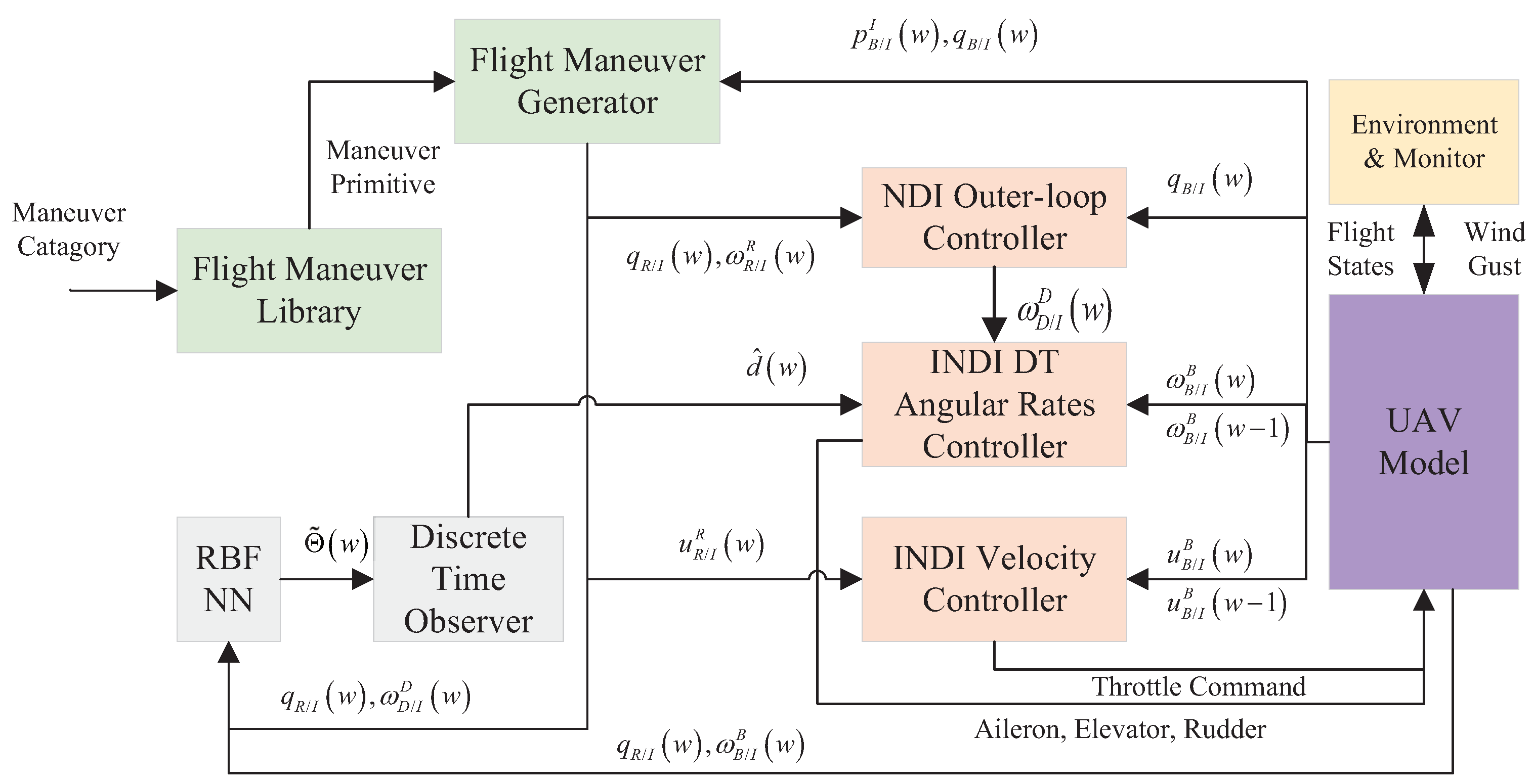
This article proposes an adaptive incremental inversion control law for the UAV system with internal and exogenous perturbations by utilizing a designed NN augmented observer. The control purpose is to design a controller and the output can track the bounded maneuvering command q R / I w , u x . All the outputs of the UAV are guaranteed bounded. The diagram of the framework is depicted in Figure 2.

3. Disturbance Observer

In this section, the design of the inner loop’s discrete-time disturbance observer is described. The modeling errors are approximated by an RBF neural network. Then, the lumped disturbance, which contains the approximation error and the external perturbations, is estimated. The adaptive law of the neural network is also presented.

3.1. Discrete-Time Disturbance Observer

Following the procedure of the design of incremental dynamic inversion controller [30], the incremental form of Equation (4) is written as
x w + 1 = 2 x w x w 1 + x F ¯ w Δ x + x F ˜ w Δ x + u G ¯ w Δ u + x G ¯ w Δ x + u G ˜ w Δ u + x G ˜ w Δ x + Δ d ¯ g u s t w
Equation (5) expressed in a more concise form is as
x w + 1 = 2 x w x w 1 + u G ¯ w Δ u + d Δ w + d l w
where d Δ w = u G ˜ w Δ u + x G ˜ w Δ x + x F ˜ w Δ x and d l w = x F ¯ w Δ x + x G ¯ w Δ x + Δ d ¯ g u s t w denote the effects of modeling perturbations, linearization errors, and the gusts, respectively. An assumption can be made that there exists a neural network to track the modeling error part d Δ w , i.e., d Δ w = Θ ¯ w + ε d , with Θ ¯ w and ε d denoting the output and the approximation error of the neural network, respectively. Hence, Equation (6) can be further rearranged as:
x w + 1 = 2 x w x w 1 + u G ¯ w Δ u + Θ ¯ w + d ¯ l w y w = x w
where d ¯ l w = d l w + ε d denotes the lumped disturbance. In order to estimate d ¯ l w , solving Equation (7) for d ¯ w yields:
d ¯ l w = x w + 1 + x w 1 2 x w u G ¯ w Δ u Θ ¯ w
For the estimation of the disturbance d ¯ l w at each time step, the actual value d ¯ l w , the estimated disturbance d ^ l w , and a constant positive gain ξ d are utilized, and the estimated d ^ l w in the next time step can be calculated as:
d ^ l w + 1 = d ^ l w + ξ d d ¯ l w d ^ l w = ξ d x w + 1 + x w 1 2 x w u G ¯ w Δ u Θ ¯ w + 1 ξ d d ^ l w
To estimate the disturbance d ^ l w , introducing an auxiliary variable Γ w as
Γ w = d ^ l w ξ d x w
Substituting Equation (9) into Equation (10) results in:
Γ w + 1 = d ^ l w + 1 ξ d x w + 1 = ξ d x w 1 2 x w u G ¯ w Δ u Θ ¯ w + 1 ξ d d ^ l w
From Equation (10), the predicted disturbance can be founded to be d ^ l w = Γ w + ξ d x w . The estimation error e D O w + 1 = d ¯ l w + 1 d ^ l w + 1 is:
e D O w + 1 = e D O w + d ¯ l w + 1 d ¯ l w Δ T ξ d d ¯ l w d l ^ w = 1 Δ T ξ d e D O w + d ¯ l w + 1 d ¯ l w
From Equation (12), it can be observed that d ¯ l w + 1 d ¯ l w is non-zero. By choosing the parameter ξ d appropriately, the estimation error e D O is globally exponentially stable.

3.2. Neural Network Estimation

This section utilizes the standard feed-forward network to approximate the uncertain item d Δ w in Equation (6), and the output is [31]:
y n n = W 1 T f W 2 T x n n = W 1 T ϕ 1 W 2 T x n n , , ϕ l W 2 T x n n T
where y n n R n , x n n R 2 n + 1 , and n and m denote the dimension of the input and output vector, respectively; W 1 R m × n , W 2 R 2 n + 1 × m represent the weight vectors. Further, l denotes the node number of NN and ϕ i represents the i-th sigmoid activation function. Utilizing the approximation capability of the NN, Θ ¯ can be further written as:
Θ ¯ = y n n = W 1 T f W 2 T x n n + ϵ
with
W i = θ W i 1 W i 11 W i 12 θ W i 2 W i 21 W i 22 T , i = 1 , 2
x n n = 1 , q 0 , q 1 , q 2 , q 3 , q 0 d , q 1 d , q 2 d , q 3 d , p , q , r , p d , q d , r d T ,
where W 1 T and W 2 T are the ideal weights vectors, which are bounded in the sense that W i W M i , i = 1 , 2 . θ W i j is the bias item and ϵ is the approximation error. The weights W i w + 1 updating rule based on discrete-time gradient descent in each step is as follows:
W ^ i 1 w + 1 = W ^ i 1 w γ ¯ 1 f w W ^ i 2 T w x n n w z 2 T w + 1 + γ ¯ 1 f w z 2 T w + 1 ς γ ¯ 1 W ^ i 1 w W ^ i 2 w + 1 = W ^ i 2 w ς γ ¯ 2 W ^ i 2 w + γ ¯ 2 x n n w f w W ^ i 1 T w z 2 w + 1
where W ^ i w + 1 represents the estimation of W i w + 1 , i = 1 , 2 . ς , γ ¯ 1 = γ 1 Δ T and γ ¯ 2 = γ 2 Δ T are positive constants, which represent the learning rates of each NN layer. The weights W ^ 1 w and W ^ 2 w are also bounded.
An equivalent to Equation (17) is:
W ˜ i 1 w + 1 = W ˜ i 1 w γ ¯ 1 f w W ^ i 2 T w x n n w z 2 T w + 1 + γ ¯ 1 f w z 2 T w + 1 ς γ 1 W ^ i 1 T w
W ˜ i 2 w + 1 = W ˜ i 2 w ς γ ¯ 2 W ^ i 2 w + γ ¯ 2 x n n w f w W ^ i 1 T w z 2 w + 1
where W ˜ i w + 1 = W ^ i w + 1 W * i w + 1 , i = 1 , 2 .
Remark 1.
Given the adaptive law described in Equation (17), the estimation error of the observer is guaranteed to be bounded. The proof is provided in the next section for brevity.

4. Controller Design

This section introduces the design of the controller for fast and slow loops. First, an incremental dynamic inversion controller for the x-axis velocity is proposed. Then, based on the previously designed disturbance observer, an NDI-based attitude controller and an INDI-based angular rates controller are proposed.

4.1. Incremental Velocity Tracking Control

Reorganize the discrete-form dynamic equation of the x-axis velocity u x from Equation (2):
u x w + 1 = u x w + L f h 1 u B / I B , q B / I , ω B / I B Δ t + L g 1 h 1 u B / I B u w Δ t + L g 2 h 2 δ t δ t Δ t
where L f h 1 · = ω B / I B w × u B / I B w e 1 Δ t + F ¯ A 1 w e 1 Δ t + A d q B / I * w g e 1 Δ t , L g 1 h 1 · = F ¯ A 1 w e 1 Δ t / u w , L g 2 h 2 F ¯ T w = F ¯ T w / δ t , e 1 = 1 , 0 , 0 T , F ¯ A 1 w and F ¯ A 2 w denote the forces on the fuselage and the actuators, respectively.
With the reference input r u x , define the tracking error as e u x w = u x w r u x w and the state equation is as follows:
e u x w + 1 = u x w + L f h 1 u B / I B , q B / I , ω B / I B Δ t + L g 1 h 1 u B / I B u w Δ t + L g 2 h 2 δ t Δ t r u x w + 1
The 1st order Taylor expansion of Equation (21) at t 0 is:
e u x w + 1 e u x w = u x w u x w 1 + u B / I B L f h 1 Δ u B / I B Δ t + q B / I L f h 1 Δ q B / I Δ t + ω B / I B L f h 1 Δ ω B / I B Δ t + L g 1 h 1 Δ u w Δ t + δ t L g 2 h 2 Δ δ t Δ t r u x w + 1 + r u x w
For fixed-wing UAV control, the thrust F ¯ T is the dominant input on x-axis; therefore, an assumption can be made [32].
Assumption A3.
For Equation (22), the inequality holds as follows:
u B / I B L f h 1 Δ u B / I B + q B / I L f h 1 Δ q B / I + ω B / I B L f h 1 Δ ω B / I B + L g 1 h 1 Δ u w 1 γ δ t δ t L g 2 h 2 Δ δ t
where γ δ t > 0 .
Substituting Equation (23) into Equation (22) results in:
e u x w + 1 e u x w + 1 + 1 γ δ t δ t L g 2 h 2 Δ δ t r u x w + 1 + r u x w
Then, the incremental control input Δ δ t can be designed in the form of feedback error e u x w 1 , e u x w :
Δ δ t = 1 + 1 γ δ t δ t L g 2 h 2 1 r u x w + 1 r u x w k a e u x w e u x w 1
From Equation (25), the design of the velocity controller merely relies on the knowledge of the matrix δ t L g 2 h 2 . Therefore, compared to the ordinary dynamic inversion approach, our method is more robust to the modeling uncertainties. The stability analysis of the proposed controller (Equation (25)) is given in the next section.

4.2. Quaternion-Based NDI in Outer Loop

In the outer loop, the controller generates the angular rates command based on the attitude reference input. To obtain the pseudo-control input of the inner loop, the discrete form of the rotational equation (Equation (2)) is described as follows:
Δ q B / I w + 1 = q B / I w + 1 q B / I w = ω B / I B w × q B / I w Δ t + O Δ q B / I w
where ω B / I B × = 1 2 0 p w q w r w p w 0 r w q w q w r w 0 p w r w q w p w 0 , O Δ q B / I w denotes the linearization error of Δ q B / I w and can be omitted. Transforming Equation (26) yields:
Δ q B / I = q B / I × ω B / I B Δ t + O Δ q B / I
where q B / I × = 1 2 q 1 q 0 q 3 q 2 q 2 q 3 q 0 q 1 q 3 q 2 q 1 q 0 T and w is omitted for brevity.
Introduce the pseudo-control input of outer loop v as v = q ˜ w / Δ T , where q ˜ w = q B / I q R / I . Then, introducing proportional gain matrix K q = d i a g k 0 , k 1 , k 2 , k 3 , k i > 0 , i = 0 , 1 , 2 , 3 results in the final form of v as follows:
v = K q q R / I q B / I
According to the principle of NDI, define the desired output as the angular rates command ω D / I D , which can be further solved:
ω D / I D = q B / I × K q q R / I q B / I + ω R / I R
where † denotes the pseudo-inversion operator, ω R / I R is the reference angular rates. It is worth noting that q B / I and ω R / I R are generated using the Learning From Demonstration approach (module named Flight Maneuver Library and Flight Maneuver Generator in Figure 2). The generation of the maneuvering command consists of the following: first, the Flight Maneuver Library receives the maneuver category and picks out the maneuver primitives, then transfers them into the Flight Maneuver Generator module. Then, the primitives are concatenated and regenerated according to the initial and terminal flight states; a more extensive study can be found in [3]. The attitude and angular rates value are obtained through a second-order filter. Distinguished from the approach using the form of Euler angles in the outer loop, we use the quaternion to circumvent the singular condition that often occurs in aerobatic maneuvers, i.e., pitch angle equals π / 2 .

4.3. Adaptive Inner-Loop Controller

Given the previous disturbance observer, the inner-loop controller aims to track the generated angular rates command ω D / I D . First, recall the discrete-form dynamic equation of the angular rates ω B / I B (Equation (7)) as follows:
x w + 1 = 2 x w x w 1 + u G ¯ w Δ u + Θ ¯ w + d ^ l w y w = x w
In Equation (30), the control matrix u G ¯ w can be calculated through linear approximation. Using a small deviation on the control output δ a , δ e , and δ r yields:
u G ¯ w G ¯ x w , u w + η u / 2 η u G ¯ x w , u w η u / 2 η u
Given that the sampling time internal δ T is sufficiently small, the spectral norm of the approximation error matrix is bounded by a positive constant ε ¯ δ ; therefore, the incremental controller can be further designed as
Δ u w = u G ¯ w 1 K ω x c w x w Θ ¯ w d ^ l w + x w 1 x w
where K ω is a positive diagonal matrix, Θ ¯ w and d ^ l w are given in Equation (14) and Equation (9), respectively.
Finally the control output at the next time step can be obtained:
u w + 1 = u w + Δ u w
Remark 2.
The control output in the angular rates loop contains δ a , δ e , and δ r . Since most of the nonlinear parts of the rotational dynamics are no longer needed, our controller is more insusceptible than the ordinary nonlinear dynamic inversion method [33]. It has to be admitted that, due to the coupled characteristics of the UAV’s rotational dynamic, the aircraft’s p, q, and r are not able to track an arbitrary reference input. Therefore, it is essential to design a feasible attitude reference trajectory in advance. In this article, we utilized the maneuver command generation method that is proposed in our previous work, and the feasibility of the reference attitude is guaranteed.
Proposition 1.
Consider the model described in Equation (2) without uncertainties or external disturbance; the output of the system (Figure 2) is locally uniformly ultimately bounded. In another word, the input–output stability of the inner and outer loops can be ensured, with x f a s t = p , q , r , u x T and x s l o w = α , β , ϕ , θ , ψ T , and ϕ, θ, ψ denote the Euler angles.
Proof. 
First, the actuators of UAV and the feedback filter are assumed as A z and H z separately. In light of ref. [30,34], the transfer function of the inner loop is:
T F f a s t = I I A z H z z 1 1 A z
Considering Equation (29), the transfer function of the outer loop only contains the diagonal matrices K q [14]. Since x f a s t = p , q , r T can track the reference value, the tracking errors of Euler angles ϕ , θ , ψ are bounded. Noting that the two remaining state variables α and β can be expressed as a function of u x , u y , u z . Assuming that the Euler angles can be controlled to the desired value ϕ = 0 , θ 0 , ψ = 0 T , the dynamic equations of u x , u y , and u z are [35]:
u ˙ x = g s i n θ 0 + 1 m X ¯ α Δ α + X ¯ β Δ β + X ¯ δ e δ e + T u ˙ y = 1 m Y ¯ α Δ α + Y ¯ β Δ β u ˙ z = g c o s θ 0 + 1 m Z ¯ α Δ α + Z ¯ β Δ β + Z ¯ δ e δ e
where X ¯ α , X ¯ β , X ¯ δ e , Y ¯ α , Y ¯ β , Z ¯ α , Z ¯ β , Z ¯ δ e are the aerodynamic parameters. Since the dynamics of α and β take the form:
α ˙ = u x u ˙ z w u ˙ x / u x 2 + u z 2 β ˙ = u ˙ y V T u y V ˙ T / V T u x 2 + u z 2
where V T = u x 2 + u y 2 + u z 2 . From Equation (35), given that the velocity u x , and assuming the side force is identically zero ( Y ¯ = 0 ), Equation (36) can then be transformed to:
α ˙ = u z u ˙ x / V T 2 , β ˙ = 0
and
u x u ˙ x + u z u ˙ z / V T = 0
we can obtain that
α ˙ = u x g cos θ 0 + 1 m Z ¯ α Δ α + 1 m Z ¯ δ e δ e V T 2 u ˙ x 2 + u ˙ z 2
Since Z ¯ α and Z ¯ δ e < 0 [36], α ˙ is negative around the equilibrium point, both of the α and β are exponentially stable. Since the filter part H z can be neglected by assuming the sampling time is infinitesimal; therefore, the transfer function merely consists of A z and K q . Supposing K q is chosen appropriately, the tracking error of x f a s t and x s l o w will converge to zero, which finishes the proof. □
Proposition 2.
Given the discrete-time UAV system with lumped disturbance (Equation (4)). Suppose the parameters of the adaptive law (Equation (17)) are chosen appropriately. In that case, the proposed neural network based INDI controller can guarantee the tracking error between ω D / I D and ω B / I B is bounded. The estimation error of the lumped disturbance is also bounded. The proof is provided in the Appendix A.

5. Evaluation

5.1. Numerical Simulations Setup

The system parameters adopted in numerical simulations are based on an F-16 aircraft model [28], and the general aerodynamic coefficients proposed by Morelli [37] are utilized. The F-16 like model has a delta wing and can perform aggressive aerobatics during dogfights. the maximum thrust-weight radio is around 1, which ensures the aircraft to perform pitch up maneuvers, such as a loop and Immelman. The moment inertial around axis X is significantly less than J y y and J z z , which means that the aircraft is agile enough to perform aggressive roll motions. Furthermore, the coefficients related to the elevator, aileron, and rudder are large enough to obtain a sufficient small response time. The attack angle α and side-slip angle β are calculated as α = arctan u z / u x and β = arcsin u y / u B / I B 2 , respectively. The total mass m, inertial matrix J, and engine model are obtained from [28]: m = 9295.44 kg, J x x = 12,874.4 kg·m2, J y y = 75,673.6 kg·m2, J z z = 85,552.1 kg·m2, and J x z = 1331.4 kg·m2. To test the robustness of the INDI_OB controller, parameter perturbations are introduced in the simulation, and the details of the perturbations are listed in Table 1. The initial condition of the simulation is obtained by trimming the UAV as: q B / I = 0.9999 , 0 , 0.0115 , 0 T , ω B / I B = 0 , 0 , 0 T , δ e = 0.0374 rad, δ a = 0 rad, δ r = 0 rad, δ t h = 1.2190 , and u B / I B = 488.7879 , 0 , 11.2121 T m/s. The wind gust model is the dryden wind turbulence and the turbulence scale length, wing span and wind speed are 20 m, 10 m and 30 m/s, respectively. In particular, a full loop maneuver is selected as reference input. The reference input contains the attitude q R / I , angular rates ω R / I R , and x-axis velocity r u x . The parameters of proposed INDI_OB controller are chosen as: γ 1 = d i a g 1.75 , 1.75 , 1.75 , γ 2 = d i a g 0.17 , 0.17 , 0.17 , η u = 0.01 rad, ς = 7.65 , k a = 10.0 , K q = d i a g 3 , 3 , 3 , 3 , and K ω = d i a g 1.0 , 1.0 , 1.0 .

5.2. Results

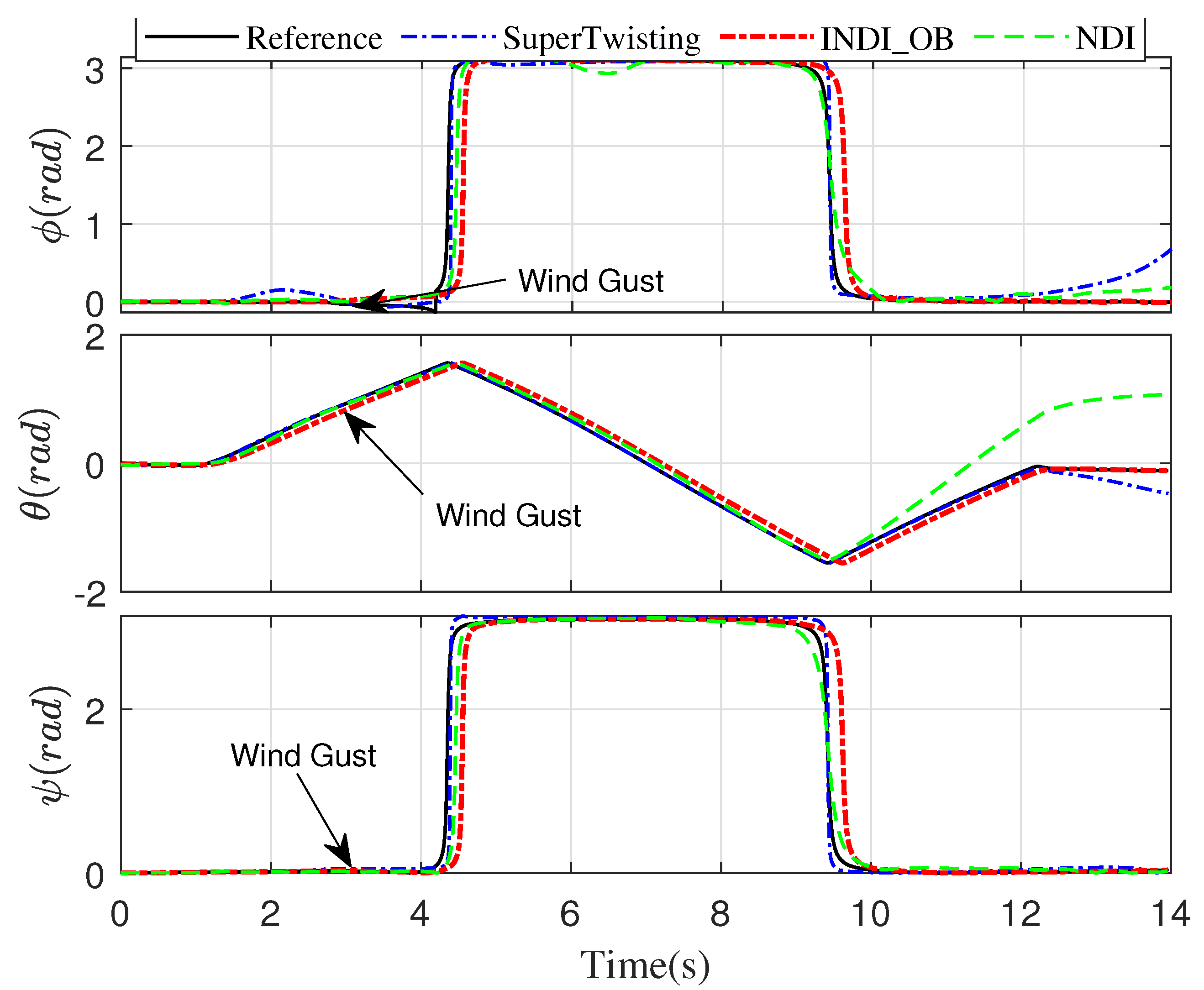
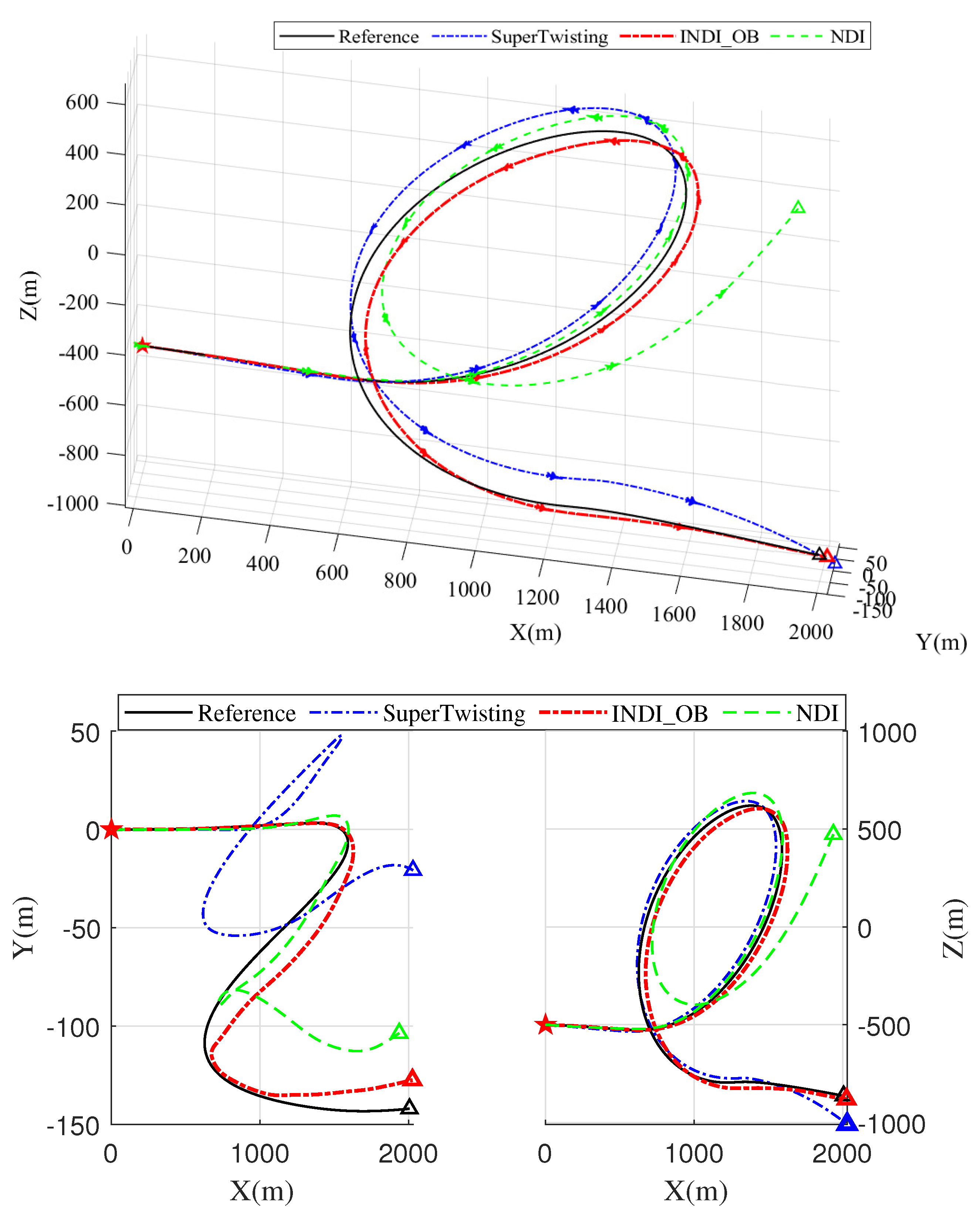
Two advanced algorithms for maneuver control are adopted for comparison. The first candidate is the super-twisting (STW) method [36]. The control object is chosen as x 1 = q ˜ w , ξ 2 = d i a g p c , q c , r c . The parameters of the controller are set as: k 2 = 6 , v 2 = 0.4 , p 0 = 1 . The second control law is the nonlinear dynamic inversion (NDI) method [33]. The tracking performance of the three aforementioned laws are compared, and the results are illustrated in Figure 3, Figure 4, Figure 5, Figure 6, Figure 7 and Figure 8. The reference input generated by the Flight Maneuver Generator module is represented by solid black lines. Blue, red, and green dashed lines represent the STW, our INDI_OB method, and the NDI method, respectively.
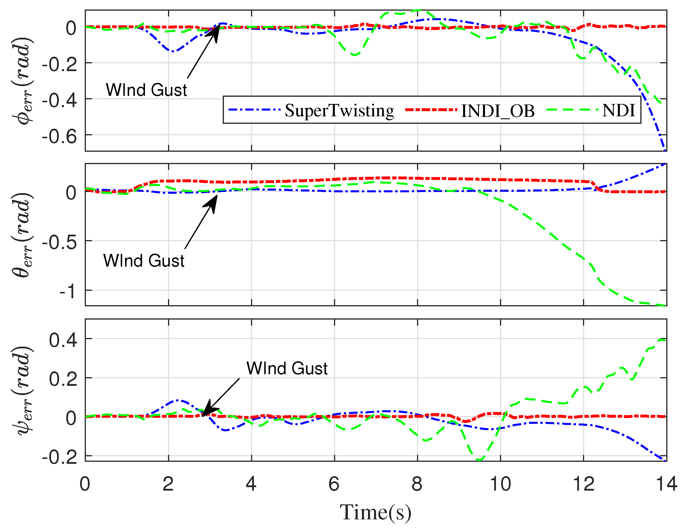
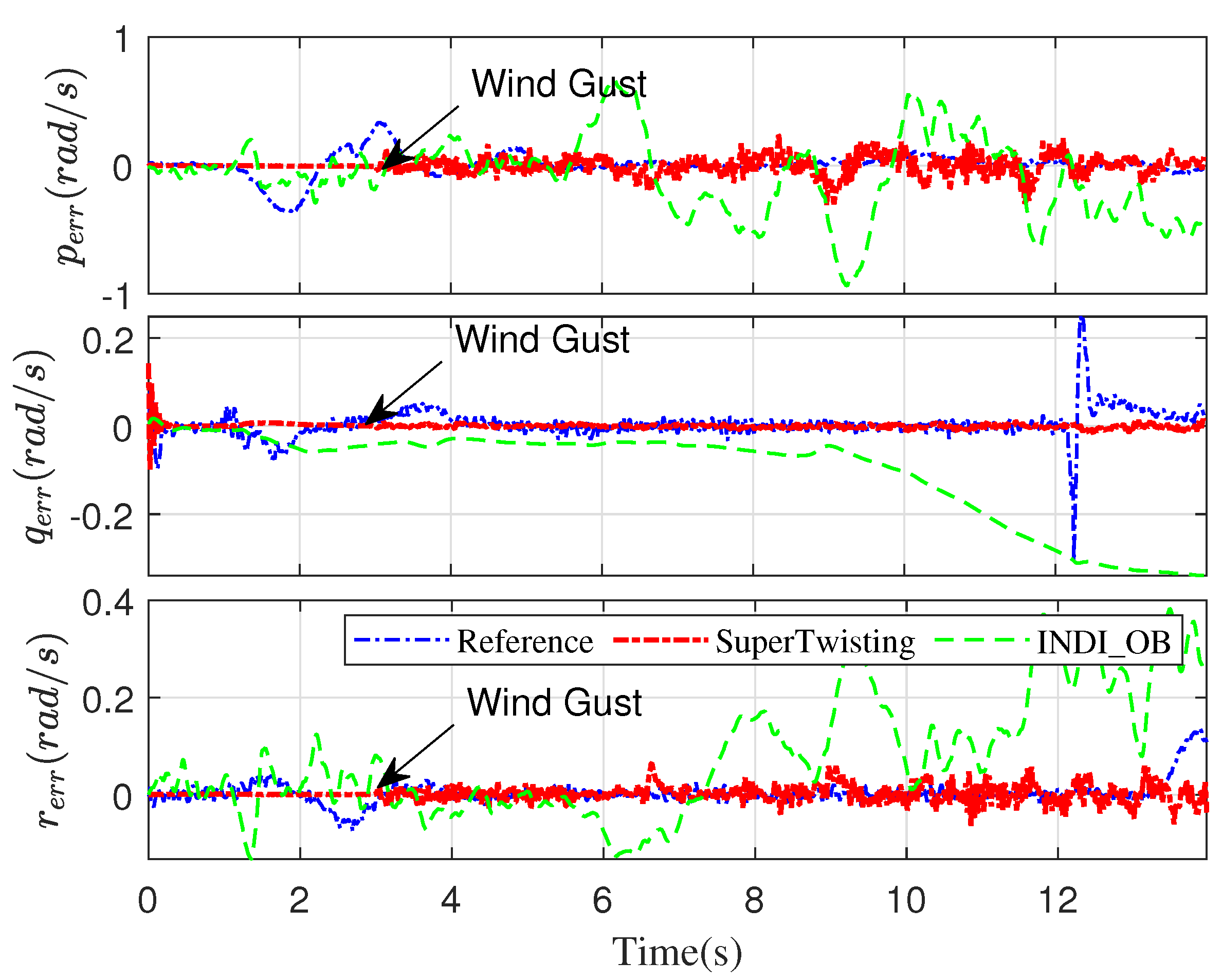
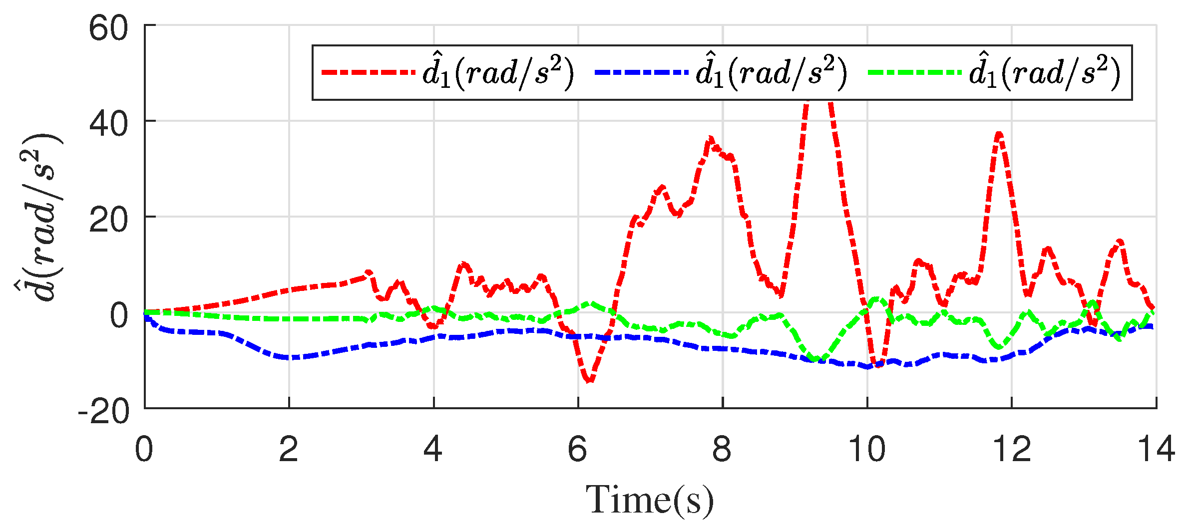
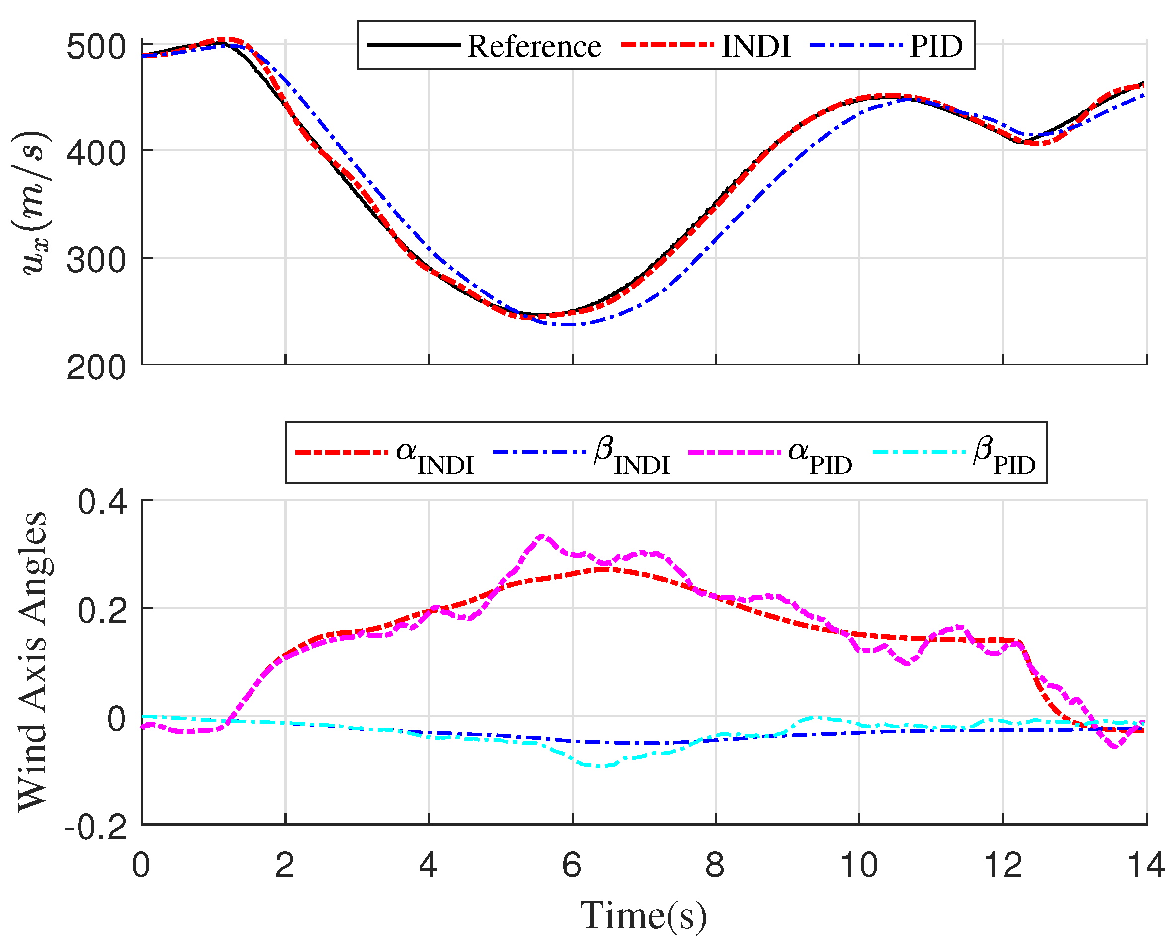
The attitude tracking results are depicted in Figure 3 and Figure 4. To be clearer and more direct, we transform the quaternion to Euler angles ϕ , θ , ψ to represent the UAV’s attitude. From Figure 3, the Euler angles converge to the reference value with INDI_OB method. With the STW and NDI laws, the tracking errors of pitch and roll angles increase notably after 10 s when the aircraft starts to recover to level flight. When the wind gust appears at t = 3 s, the angular rates tracking error of INDI_OB shows the least performance degradation compared to the STW and NDI methods. In Figure 6, the estimated values of the lumped disturbance are illustrated. Furthermore, the comparative results of INDI and PID controllers in velocity tracking are depicted in Figure 7. Note that, the incremental velocity controller shows better tracking performance due to its inherent exponential convergence ability. Furthermore, from Figure 7, the attack and side-slip angles α , β of I N D I method are more smooth. It is worth noting that considering the INDI-based velocity controller only depends on a few model parameters of the UAV; this method is more robust to model mismatches than the other model-based velocity controller. From Figure 8, it can be observed that the tracking performance of INDI_OB shows the least deviations against wind gust and model mismatch.
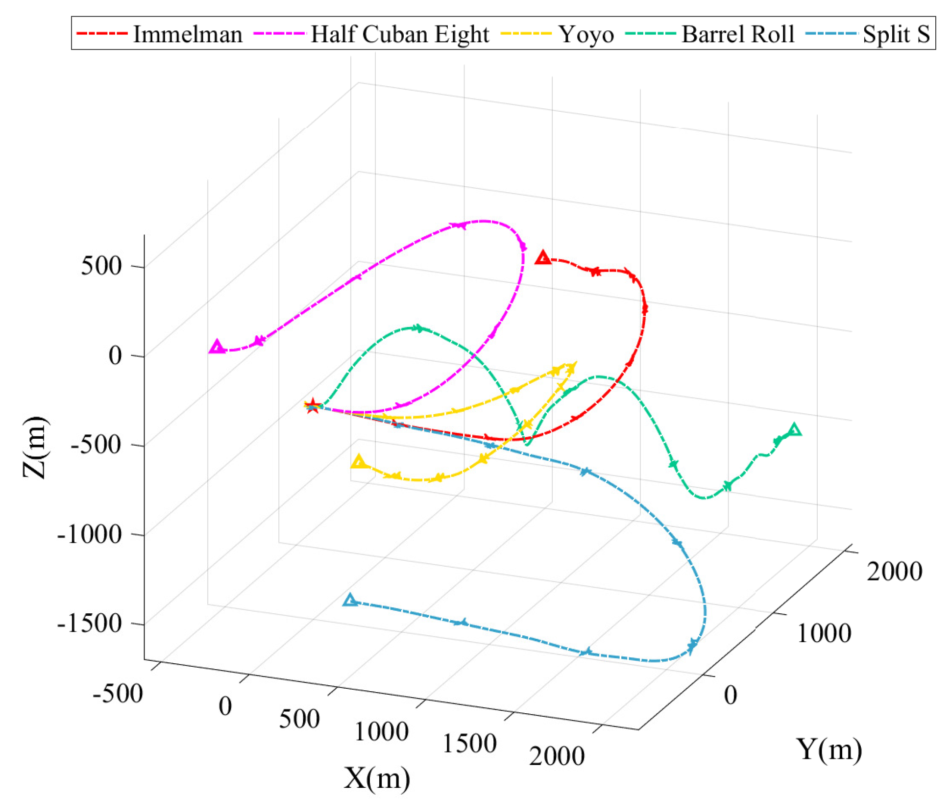
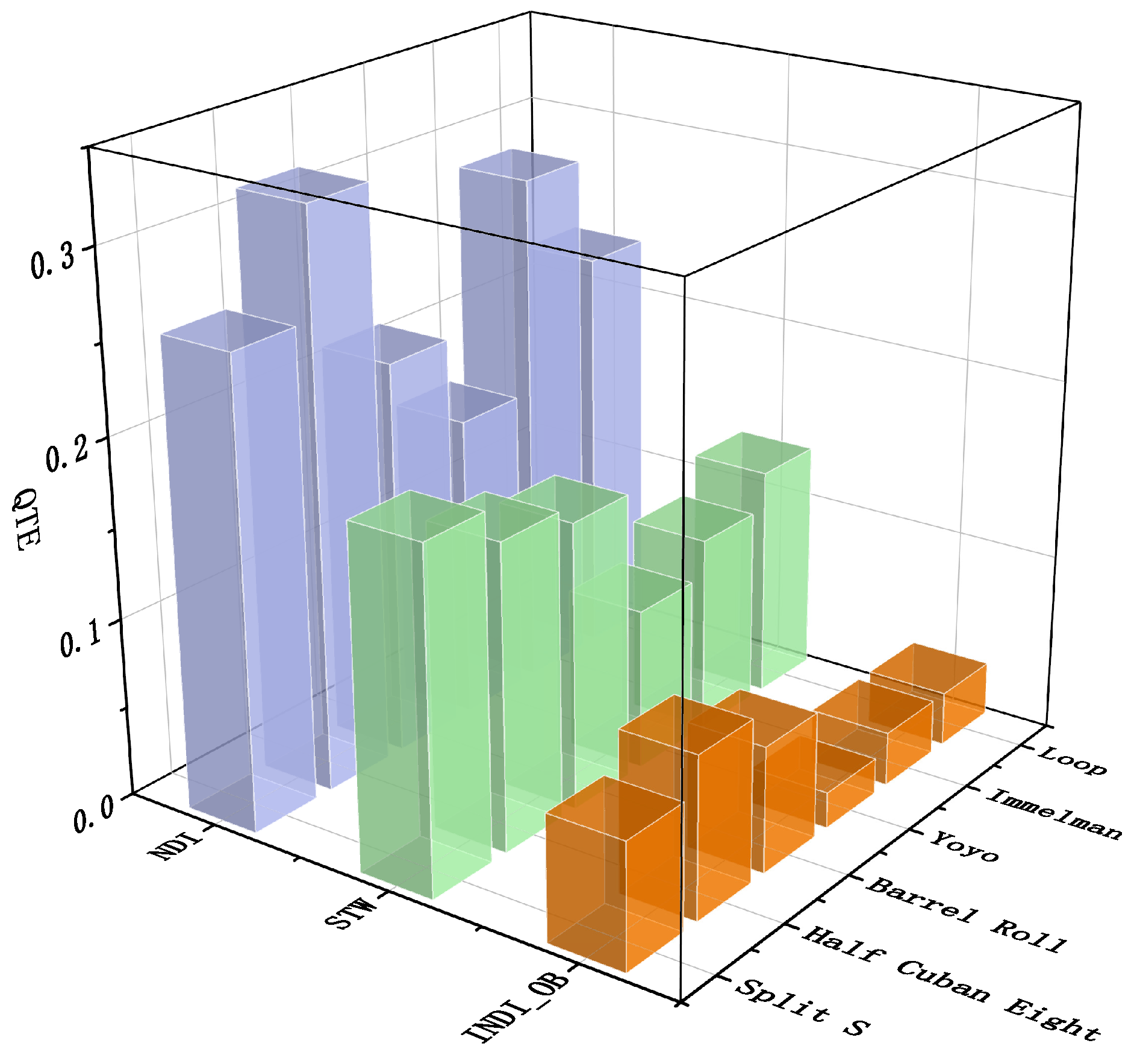
In addition, to further analyze the attitude tracking performance of the comparative methods, five other classic maneuvers named the Immmelman, Half Cuban Eight, Yoyo, Barrel Roll, and Split S are performed. The metric of the quaternion tracking error Q T E is:
Q T E = 1 N k = 1 N arccos q ˜ 0 w 1 cos q ˜ 0 w 2 , q ˜ 0 w < 1 0 , o t h e r c a s e s
where q ˜ 0 w denotes the first item of the tracking error quaternion, N is the total sample steps, and Δ t is the sampling interval. The simulation results of trajectories and Q T E are illustrated in Figure 9 and Figure 10, respectively. Only the tracking results of the INDI_OB law are illustrated for conciseness. From Figure 10, the NDI law has significant tracking deviations compared to the other methods. Furthermore, the comparative small Q T E of INDI_OB shows more robustness to model mismatch and wind gust due to the neural network based disturbance observer; therefore, the INDI_OB scheme has an obvious advantage in agile maneuver tracking. To conclude, the advantages of the proposed approach are illustrated, thus verifying the effectiveness of the developed approach.

6. Conclusions

This article developed a physics-based control framework capable of performing various maneuvers. First, we designed a disturbance observer incorporating a radial basis neural network considering the perturbations of aerodynamic parameters and wind gusts. Then, the quaternion-based inversion controller was introduced for attitude tracking. The adaptive INDI method was then proposed to track angular rates and velocity with the lumped disturbance estimation. Rigorous stability analysis and extensive comparative simulation demonstrate the effectiveness of our method.
Future work will focus on this maneuver tracking controller in the motion planning framework to realize real-time obstacle avoidance.

Author Contributions

Conceptualization, H.Y.; methodology, S.C.; software, S.C.; validation, S.C. and H.Y.; formal analysis, H.Y.; investigation, S.C.; resources, H.Y.; data curation, S.C.; writing—original draft preparation, S.C.; writing—review and editing, H.Y.; visualization, S.C.; supervision, H.Y.; project administration, H.Y.; funding acquisition, H.Y. All authors have read and agreed to the published version of the manuscript.

Funding

This research was funded by the National Natural Science Foundation of China under Grant 51905537 and Natural Science Foundation of Hunan Province: 2021JJ10053.

Data Availability Statement

Not applicable.

Acknowledgments

The authors would like to appreciate Lv Fei for performing flight demonstrations.

Conflicts of Interest

The authors declare no conflict of interest.

Abbreviations

The following abbreviations are used in this manuscript:
INDIIncremental nonlinear dynamic inversion
STWSuper-twisting
INFT_OBIncremental finite time controller with observer
NDINonlinear dynamic inversion

Appendix A. Proof of Proposition 2

Proof. 
Define the tracking errors of the attitude and the angular rates as z 1 w = q B / I w q R / I w and z 2 w = ω B / I B w ω D / I D w . To analyze the tracking error boundedness, consider a Lyapunov function as:
L w = η 1 z 1 T w z 1 w + η 2 z 2 T w z 2 w + i = 1 3 d ˜ i 2 w + i = 1 3 1 γ ¯ 1 W ˜ i 1 T w W ˜ i 1 w + i = 1 3 1 γ ¯ 2 W ˜ i 2 T w W ˜ i 2 w
where η > 0 , and d ˜ i 2 w denotes the estimation error of the lumped disturbance. By differentiating L w , one has:
Δ L w = L w + 1 L w = η 1 z 1 T w + 1 z 1 T w + 1 + η 2 z 2 T w + 1 z 2 T w + 1 η 1 z 1 T w z 1 T w η 2 z 2 T w z 2 w + i = 1 3 1 γ ¯ 1 W ˜ i 1 T w + 1 W ˜ i 1 w + 1 + i = 1 3 d ˜ i 2 w + 1 + i = 1 3 1 γ ¯ 2 W i 2 T w + 1 W ˜ i 2 w + 1 i = 1 3 d ˜ i 2 w i = 1 3 1 γ ¯ 1 W ˜ i 1 T w W ˜ i 1 w i = 1 3 1 γ ¯ 2 W ˜ i 2 T w W ˜ i 2 w
Substituting the definition of z 1 w into the first item yields
η 1 z 1 T w + 1 z 1 w + 1 η 1 z 1 T w z 1 w = η 1 z 1 T w z 1 w + 1 4 η 1 z 2 T w z 2 w
Furthermore, according to Equation (17) one can obtain
i = 1 3 1 γ ¯ 1 W ˜ i 1 T w + 1 W ˜ i 1 w + 1 = i = 1 3 W ˜ i 1 T w + 1 1 γ ¯ 1 W ˜ i 1 w + f w z 2 w i = 1 3 W ˜ i 1 T w + 1 f w W ^ 2 w x n n w z 2 w i = 1 3 ς W ˜ i 1 w + 1 W ^ 1 w
Similarly,
i = 1 3 1 γ ¯ 2 W ˜ i 2 T w + 1 W ˜ i 2 w + 1 = i = 1 3 W ˜ i 2 T w + 1 1 γ ¯ 2 W ˜ i 2 w ς W ^ i 2 w + i = 1 3 W ˜ i 2 T w + 1 x n n w f w W ^ i 1 w z 2 w
where f w = f W ^ 2 T w x n n w and f w = f W ^ 2 T w x n n w .
Furthermore, following a simple computation results in:
i = 1 3 ς W ˜ i 1 T w + 1 W ^ i 1 w = i = 1 3 ς W ˜ i 1 T w + ς γ ¯ 1 f w z 2 T w W ^ i 1 w + i = 1 3 ς γ ¯ 1 f w W ^ i 2 T w x n n w z 2 w T W ^ i 1 w + i = 1 3 ς 2 γ ¯ 1 W ^ i 1 T w W ^ i 1 w
Similarly, one has
i = 1 3 W ˜ i 1 T w + 1 f w z 2 w = i = 1 3 W ˜ i 1 T w γ ¯ 1 ς W ^ i 1 T w f w z 2 w i = 1 3 γ ¯ 1 f w W ^ i 2 T w x n n w z 2 T w f T w z 2 w + i = 1 3 γ ¯ 1 z 2 T w f T w f w z 2 w
and
i = 1 3 ς W ˜ i 2 T w + 1 W ^ i 2 w = i = 1 3 ς W ˜ i 2 T w + γ ¯ 2 ς 2 W ^ i 2 T w W ^ i 2 w i = 1 3 γ ¯ 2 ς x n n w f w W ^ i 1 T w z 2 w W ^ i 2 w
and
i = 1 3 1 γ ¯ 2 W ˜ i 2 T w + 1 W ˜ i 2 w = i = 1 3 1 γ ¯ 2 ς W ˜ i 2 T w W ˜ i 2 w + i = 1 3 x n n w f w W ^ i 1 T w z w T W ˜ i 2 w
and
2 i = 1 3 ς W ˜ i j T w W ^ i j w = i = 1 3 ς W ˜ i j T w 2 i = 1 3 ς W ^ i j T w 2 + i = 1 3 ς W ^ i j * T w 2 , j = 1 , 2
Results in
Δ L ( w ) = η 1 z 1 T ( w + 1 ) z 1 ( w + 1 ) + η 2 z 2 T ( w + 1 ) z 2 ( w + 1 ) η 1 z 1 T ( w ) z 1 ( w ) η 2 z 2 T ( w ) z 2 ( w ) + i = 1 3 d ˜ i 2 ( w + 1 ) i = 1 3 d ˜ i 2 ( w ) i = 1 3 s W ˜ i ( 1 ) ( w ) 2 + W ^ i ( 1 ) ( w ) 2 i = 1 3 ς W ˜ i ( 2 ) ( w ) 2 i = 1 3 ς W ^ i ( 2 ) ( w ) 2 + i = 1 3 ς W i ( 2 * ) ( w ) 2 + i = 1 3 ς W i ( 1 * ) ( w ) 2 2 i = 1 3 γ ¯ 1 f ( w ) x n n ( w ) f ( w ) W ^ i ( 2 ) T ( w ) z 2 ( w + 1 ) 2 2 i = 1 3 γ ¯ 1 ς W ^ i ( 1 ) T ( w ) f ( w ) z 2 ( w + 1 ) + i = 1 3 γ ¯ 1 f ( w ) x n n ( w ) z 2 ( w + 1 ) T W ^ i ( 2 ) ( w ) 2 + i = 1 3 γ ¯ 2 f ( w ) x n n ( w ) z 2 ( w + 1 ) T W ^ i ( 1 ) ( w ) 2
where
η 2 z 2 T w + 1 z 2 w + 1 = η 2 z 2 T w + 1 v + d ˜ w Θ ˜ w
and we can further obtain several equations and inequalities:
η 1 z 1 T w + 1 z 1 w + 1 η 1 z 1 T w z 1 w = η 1 z 1 T w z 1 w + 1 4 η 1 z 2 T w z 2 w
2 η 2 z 2 T w + 1 d ˜ w η 2 2 z 2 T w + 1 2 + d ˜ 2 w
2 Θ ˜ w z 2 w + 1 = 2 i = 1 3 W ˜ i 1 T w f w z 2 w + 1 + τ ¯ + 2 i = 1 3 W ^ i 1 T w f w W ˜ i 2 T w x n n w z 2 w + 1 2 i = 1 3 W ˜ i 1 T w f w W ^ i 2 T w x n n w z 2 w + 1
2 i = 1 3 γ 1 ς W ^ i 1 T w f w z 2 w + 1 γ 1 ς f max 2 z 2 w + 1 2 + γ 1 ς i = 1 3 W ^ i 1 T w 2
where Θ ˜ is the estimation error of the model uncertainties and τ ¯ is a constant.
According to [20]:
d ˜ 2 w + 1 d ˜ 2 w σ 1 1 d ˜ 2 w + σ 2 W ˜ 1 w 2 + σ 3 W ˜ 2 w 2 + σ 4 W ^ 1 w 2 + σ 5 W ^ 2 w 2
and
γ 1 f w z 2 w + 1 2 γ 1 f max 2 z 2 w + 1 2
where σ 1 , σ 2 , σ 3 , σ 4 and σ 5 are constants. We can obtain the following inequality according to Equations (A5)–(A9):
Δ L κ ¯ 2 z 1 w 2 κ ¯ 3 W ˜ 1 w 2 κ ¯ 4 W ˜ 2 w 2 κ ¯ 5 W ^ 1 w 2 κ ¯ 6 W ^ 2 w 2 κ ¯ 7 z 2 w + 1 2 κ ¯ 8 z 2 w 2 κ ¯ 9 d ˜ 2 w 2 + κ ¯ 10
where κ ¯ 2 = η 1 , κ ¯ 3 = ς σ 2 , κ ¯ 4 = ς σ 3 , κ ¯ 5 = ς γ ¯ 1 ς 2 γ ¯ 1 ς σ 4 , κ ¯ 6 = ς γ ¯ 2 ς 2 σ 5 , κ ¯ 7 = 2 η 2 η 2 2 η 1 2 γ 1 ς f max 2 , κ ¯ 8 = η 2 1 4 η 1 , κ ¯ 9 = 1 σ 1 η 2 2 , κ ¯ 10 = τ ¯ + i = 1 3 ς W i 1 w 2 + i = 1 3 ς W i 2 w 2 . where κ ¯ i are constant. Considering the UAV model described above, the neural network-based discrete time disturbance observer and the increment d u w could be further designed with the appropriate parameters,. By utilizing the proposed neural network based control scheme, the difference between q B / I w and q R / I w , ω B / I B w and ω D / I D w are guaranteed to be bounded, which finishes the proof. □

References

  1. Levin, J.M.; Paranjape, A.A.; Nahon, M. Agile maneuvering with a small fixed-wing unmanned aerial vehicle. Robot. Auton. Syst. 2019, 116, 148–161. [Google Scholar] [CrossRef]
  2. Kaufmann, E.; Loquercio, A.; Ranftl, R.; Müller, M.; Koltun, V.; Scaramuzza, D. Deep drone acrobatics. arXiv 2020, arXiv:2006.05768. [Google Scholar]
  3. Cao, S.; Wang, X.; Zhang, R.; Yu, H.; Shen, L. From Demonstration to Flight: Realization of Autonomous Aerobatic Maneuvers for Fast, Miniature Fixed-Wing UAVs. IEEE Robot. Autom. Lett. 2022, 7, 5771–5778. [Google Scholar] [CrossRef]
  4. Stevens, B.L.; Lewis, F.L.; Johnson, E.N. Aircraft Control and Simulation: Dynamics, Controls Design, and Autonomous Systems; John Wiley & Sons: Hoboken, NJ, USA, 2015. [Google Scholar]
  5. Boyd, S.; Barratt, C. Linear Controller Design: Limits of Performance; Technical Report; Stanford University: Stanford, CA, USA, 1991. [Google Scholar]
  6. Nguyen, L.T. Simulator Study of Stall/Post-Stall Characteristics of a Fighter Airplane with Relaxed Longitudinal Static Stability; National Aeronautics and Space Administration: Washington, DC, USA, 1979; Volume 12854. [Google Scholar]
  7. MacKunis, W.; Wilcox, Z.D.; Kaiser, M.K.; Dixon, W.E. Global adaptive output feedback tracking control of an unmanned aerial vehicle. IEEE Trans. Control Syst. Technol. 2010, 18, 1390–1397. [Google Scholar] [CrossRef] [Green Version]
  8. Slotine, J.J.E.; Li, W. Applied Nonlinear Control; Prentice Hall: Englewood Cliffs, NJ, USA, 1991; Volume 199. [Google Scholar]
  9. Reiner, J.; Balas, G.J.; Garrard, W.L. Flight control design using robust dynamic inversion and time-scale separation. Automatica 1996, 32, 1493–1504. [Google Scholar] [CrossRef]
  10. Da Costa, R.; Chu, Q.; Mulder, J. Reentry flight controller design using nonlinear dynamic inversion. J. Spacecr. Rocket. 2003, 40, 64–71. [Google Scholar] [CrossRef]
  11. Bacon, B.; Ostroff, A. Reconfigurable flight control using nonlinear dynamic inversion with a special accelerometer implementation. In Proceedings of the AIAA Guidance, Navigation, and Control Conference and Exhibit, Denver, CO, USA, 14–17 August 2000; p. 4565. [Google Scholar]
  12. Cao, S.; Wang, X.; Yu, H. Real-time Maneuver Command Generation and Tracking For a Miniature Fixed-Wing Drone with a Ducted-Fan Unit. In Proceedings of the 2021 60th IEEE Conference on Decision and Control (CDC), Austin, TX, USA, 14–17 December 2021; pp. 3591–3596. [Google Scholar]
  13. Sieberling, S.; Chu, Q.; Mulder, J. Robust flight control using incremental nonlinear dynamic inversion and angular acceleration prediction. J. Guid. Control Dyn. 2010, 33, 1732–1742. [Google Scholar] [CrossRef]
  14. Smeur, E.J.; Chu, Q.; de Croon, G.C. Adaptive incremental nonlinear dynamic inversion for attitude control of micro air vehicles. J. Guid. Control Dyn. 2015, 38, 450–461. [Google Scholar] [CrossRef] [Green Version]
  15. Wang, X.; Van Kampen, E.; Chu, Q.; De Breuker, R. Flexible Aircraft Gust Load Alleviation with Incremental Nonlinear Dynamic Inversion. J. Guid. Control Dyn. 2019, 42, 1–18. [Google Scholar] [CrossRef] [Green Version]
  16. Acquatella, P.; van Ekeren, W.; Chu, Q.P. PI (D) tuning for Flight Control Systems via Incremental Nonlinear Dynamic Inversion. IFAC-PapersOnLine 2017, 50, 8175–8180. [Google Scholar] [CrossRef]
  17. Wang, N.; Zhang, T.; Yi, Y.; Wang, Q. Adaptive control of output feedback nonlinear systems with unmodeled dynamics and output constraint. J. Frankl. Inst. 2017, 354, 5176–5200. [Google Scholar] [CrossRef]
  18. Sharafian, A.; Bagheri, V.; Zhang, W. RBF neural network sliding mode consensus of multiagent systems with unknown dynamical model of leader-follower agents. Int. J. Control Autom. Syst. 2018, 16, 749–758. [Google Scholar] [CrossRef]
  19. Fei, J.; Lu, C. Adaptive Sliding Mode Control of Dynamic Systems Using Double Loop Recurrent Neural Network Structure. IEEE Trans. Neural Netw. Learn. Syst. 2018, 29, 1275–1286. [Google Scholar] [CrossRef] [PubMed]
  20. Chen, M.; Shao, S.; Jiang, B. Adaptive Neural Control of Uncertain Nonlinear Systems Using Disturbance Observer. IEEE Trans. Cybern. 2017, 47, 3110–3123. [Google Scholar] [CrossRef]
  21. Razmi, H.; Afshinfar, S. Neural network-based adaptive sliding mode control design for position and attitude control of a quadrotor UAV. Aerosp. Sci. Technol. 2019, 91, 12–27. [Google Scholar] [CrossRef]
  22. Patan, K. Two stage neural network modelling for robust model predictive control. ISA Trans. 2018, 72, 56–65. [Google Scholar] [CrossRef]
  23. Li, X.J.; Yang, G.H. Neural-network-based adaptive decentralized fault-tolerant control for a class of interconnected nonlinear systems. IEEE Trans. Neural Netw. Learn. Syst. 2016, 29, 144–155. [Google Scholar] [CrossRef]
  24. Shastry, A.K.; Pattanaik, A.; Kothari, M. Neuro-adaptive augmented dynamic inversion controller for quadrotors. IFAC-PapersOnLine 2016, 49, 302–307. [Google Scholar] [CrossRef]
  25. Li, D.P.; Liu, Y.J.; Tong, S.; Chen, C.P.; Li, D.J. Neural networks-based adaptive control for nonlinear state constrained systems with input delay. IEEE Trans. Cybern. 2019, 49, 1249–1258. [Google Scholar] [CrossRef]
  26. Khaghani, M.; Skaloud, J. Assessment of VDM-based autonomous navigation of a UAV under operational conditions. Robot. Auton. Syst. 2018, 106, 152–164. [Google Scholar] [CrossRef]
  27. Hoffman, D.; Rehan, M.; MacKunis, W.; Reyhanoglu, M. Quaternion-based Robust Trajectory Tracking Control of a Quadrotor Hover System. Int. J. Control Autom. Syst. 2018, 16, 2575–2584. [Google Scholar] [CrossRef]
  28. Sonneveldt, L. Nonlinear F-16 Model Description; Delft University of Technology: Delft, The Netherlands, 2006. [Google Scholar]
  29. Wang, X.; Han, D.; Yu, C.; Zheng, Z. The geometric structure of unit dual quaternion with application in kinematic control. J. Math. Anal. Appl. 2012, 389, 1352–1364. [Google Scholar] [CrossRef] [Green Version]
  30. Wang, X.; Van Kampen, E.J.; Chu, Q.P.; Lu, P. Stability Analysis for Incremental Nonlinear Dynamic Inversion Control. In Proceedings of the 2018 AIAA Guidance, Navigation, and Control Conference, Kissimmee, FL, USA, 8–12 January 2018; p. 1115. [Google Scholar]
  31. Krüger, T.; Schnetter, P.; Placzek, R.; Vörsmann, P. Fault-tolerant nonlinear adaptive flight control using sliding mode online learning. Neural Netw. 2012, 32, 267–274. [Google Scholar] [CrossRef] [PubMed]
  32. Ramírez, J.C.H.; Nahon, M. A gravity-referenced moving frame for vehicle path following applications in 3d. IEEE Robot. Autom. Lett. 2021, 6, 4393–4400. [Google Scholar] [CrossRef]
  33. Shao, S.; Chen, M.; Zhang, Y. Adaptive discrete-time flight control using disturbance observer and neural networks. IEEE Trans. Neural Netw. Learn. Syst. 2019, 30, 3708–3721. [Google Scholar] [CrossRef]
  34. Bhardwaj, P.; Raab, S.A.; Zhang, J.; Holzapfel, F. Integrated Reference Model for a Tilt-rotor Vertical Take-off and Landing Transition UAV. In Proceedings of the 2018 Applied Aerodynamics Conference, Atlanta, GA, USA, 25–29 June 2018; p. 3479. [Google Scholar]
  35. Sonneveldt, L.; Chu, Q.; Mulder, J. Constrained adaptive backstepping flight control: Application to a nonlinear F-16/MATV model. In Proceedings of the AIAA Guidance, Navigation, and Control Conference and Exhibit, Keystone, CO, USA, 21–24 August 2006; p. 6413. [Google Scholar]
  36. Raj, K.; Muthukumar, V.; Singh, S.N.; Lee, K.W. Finite-time sliding mode and super-twisting control of fighter aircraft. Aerosp. Sci. Technol. 2018, 82, 487–498. [Google Scholar] [CrossRef]
  37. Grauer, J.A.; Morelli, E.A. Generic global aerodynamic model for aircraft. J. Aircr. 2015, 52, 13–20. [Google Scholar] [CrossRef]
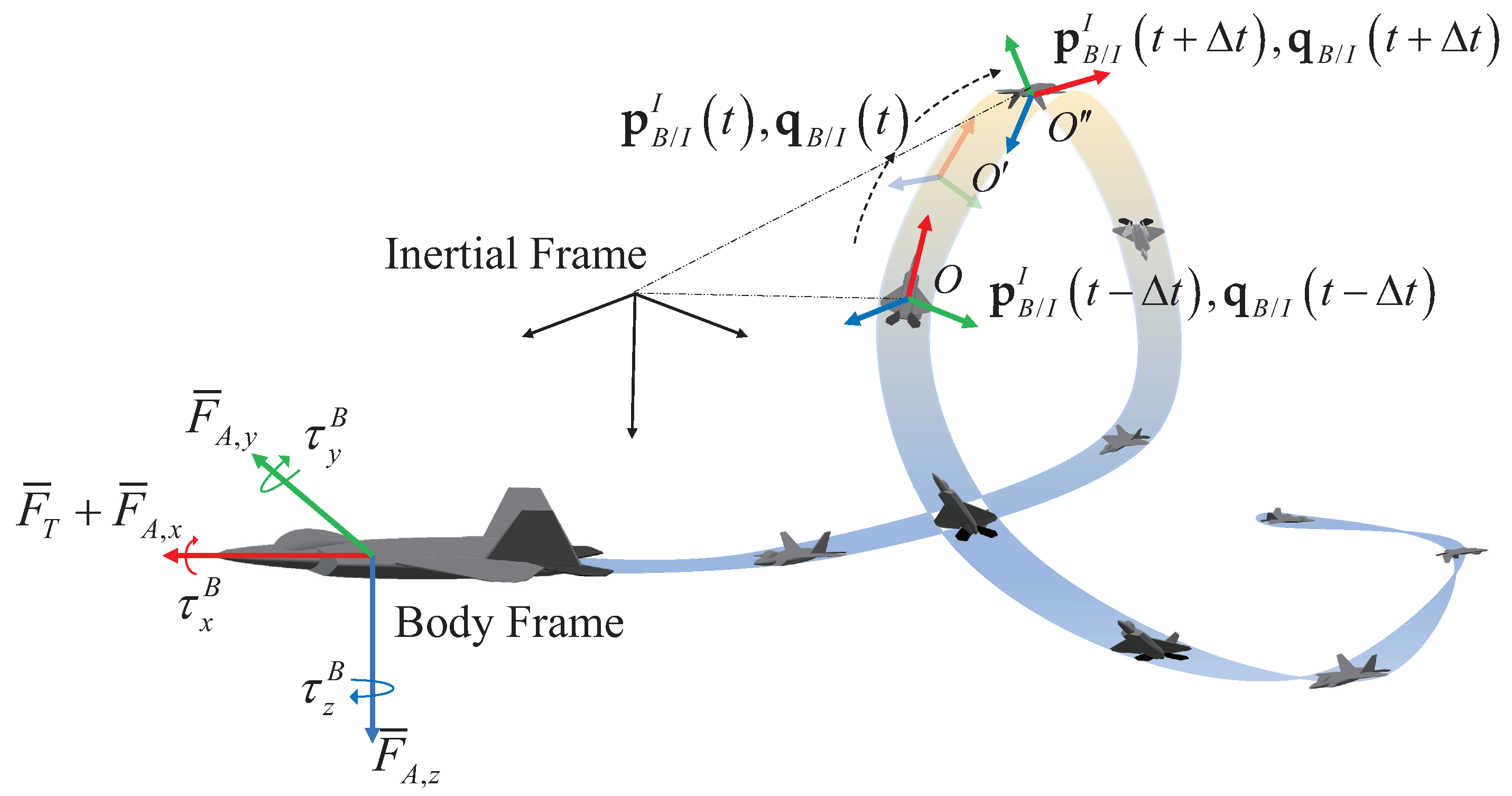
Figure 1. The UAV performs the loop maneuver. The definitions of the body and inertial frames and the construction of the UAV are also illustrated.
Drones 06 00316 g001
Figure 2. Block diagram of the total system and controllers.
Drones 06 00316 g002
Figure 3. Euler angles during the loop maneuver under the proposed INFT_OB scheme and two comparative NDI and STW schemes.
Drones 06 00316 g003
Figure 4. Attitude tracking errors during the loop maneuver under the proposed INFT_OB scheme and two comparative NDI and STW schemes.
Drones 06 00316 g004
Figure 5. Angular rates tracking errors during the loop maneuver under the proposed INFT_OB scheme and two comparative NDI and STW schemes.
Drones 06 00316 g005
Figure 6. Estimation of d l under the disturbance observer in INFT_OB.
Drones 06 00316 g006
Figure 7. The comparison of velocity tracking performance.
Drones 06 00316 g007
Figure 8. Trajectory tracking results of the loop maneuver.
Drones 06 00316 g008
Figure 9. Simulation results of the selected five classic maneuvers using the proposed INDI_OB method.
Drones 06 00316 g009
Figure 10. The metric of attitude tracking error for six classic maneuvers.
Drones 06 00316 g010
Table 1. Parameters set in test case.
ParametersMismatch
C l δ a , δ r , C m δ e , C n δ a , δ r ± 50 %
C x δ e , q , C y δ a , δ r , p , r , C z δ e , q ± 30 %
Mass, Gravity Center ± 50 %
I x x , I y y , I z z , I x z ± 30 %
Publisher’s Note: MDPI stays neutral with regard to jurisdictional claims in published maps and institutional affiliations.