Abstract
Flocking navigation, involving alignment-guaranteed path following and collision avoidance against obstacles, remains to be a challenging task for drones. In this paper, we investigate how to implement flocking navigation when only one drone in the swarm masters the predetermined path, instead of all drones mastering their routes. Specifically, this paper proposes a hierarchical weighting Vicsek model (WVEM), which consists of a hierarchical weighting mechanism and a layer regulation mechanism. Based on the hierarchical mechanism, all drones are divided into three layers and the drones at different layers are assigned with different weights to guarantee the convergence speed of alignment. The layer regulation mechanism is developed to realize a more flexible obstacle avoidance. We analyze the influence of the WVEM parameters such as weighting value and interaction radius, and demonstrate the flocking navigation performance through a series of simulation experiments.
1. Introduction
In recent years, researchers are showing growing interests in drone swarms, among which flocking navigation is particularly eye-catching. Flocking behaviors refer to the emergence of group-level phenomena through simple individual interactions and probably arise from local rules without the central coordination [1,2,3]; navigation refers to the swarm tracking a predetermined path [4].
There are a great deal of studies that can achieve flocking navigation successfully by assuming that all drones have access to the predetermined path information [5,6,7]. If all drones need to master the path information, the data transmitting load is heavy, or it is simply difficult to achieve. On the one hand, the drones receive the predetermined path from the ground station in remote control mode. Then, all drones should be equipped with communicators, which in turn, causes a heavy data transmitting load. On the other hand, the drones are designed to plan their path based on the perceived goal position in autonomous control mode, but the capability of path planning varies a lot; thus, maybe only few of them can accomplish the planning task by obtaining the goal information and selecting the path accordingly and correctly. Furthermore, the noncooperation goal position may not be accurately expressed and the path information may not be transmitted for the interruption of communication. Therefore, it is a meaningful task to navigate the flocking with only one drone mastering the path information. At the same time, it is also a challenging one due to the requirements of rapid convergence and obstacle avoidance under the limited interaction radius.
To achieve flocking navigation, we need to ensure that all drones align to the path of the information drone who means the drone that knows the predetermined path. As a classic flocking model, the Vicsek model (VEM) describes the system where individuals align their movement directions to those individuals within a local neighborhood, and all individuals in the flock eventually align [8]. Taking the advantage of the alignment properties of VEM, as long as all the drones successfully make themselves align with the information drone within a short enough time, they can follow with the information drone closely; thus, the swarm can move along the desired path.
To achieve alignment as soon as possible, the topology relationship is established according to the information held by the drone and the interaction radius. Related studies have suggested that if the hierarchy exists and if several drones are not easily influenced by other drones, they can induce of the movement of the Vicsek-model swarm [9,10,11]. A hierarchical structure—dividing all drones into drones, drones, and drones—is established in this paper to guarantee enough influence of the crucial information, as shown in Figure 1. Besides, the information is no longer limited to the path information and can also include information about the perceived obstacles. A layer-regulation mechanism is also designed to ensure rapid alignment with the drones that detect the obstacle, which leads to the more flexible obstacle avoidance.
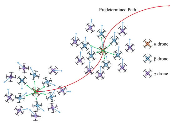
Figure 1.
The scenario of flocking navigation. The drones’ movements are chaotic and disordered at the beginning. Only the drone masters the path information and it adjusts its heading angle accordingly. The drone whose perception range covers the drone ( drone with blue color) can perceive the information of the drone, while the drone whose range does not cover the drone ( drone with purple color) cannot perceive it directly.
Accordingly, this paper proposes the hierarchical weighting Vicsek model (WVEM), including the hierarchical weighting mechanism and the layer regulation mechanism. The hierarchical weighting mechanism is designed to improve the convergence speed of alignment with the information drone, and the layer regulation mechanism is to improve the performance of obstacle avoidance.
The rest of this paper is organized as follows. In Section 2, we introduce some background work including VEM and several matrixes. Section 3 proposes the WVEM and the WVEM-based flocking algorithm. Numerous simulations are carried out in Section 4 to verify and analyze the model performance. The last section summarizes all the points of this paper.
2. Related Works
This section firstly introduces the classic Vicsek Model and a detailed description of the involved parameters. Then, we introduce several coefficient matrixes to describe the relationship among drones in the flocking.
2.1. Vicsek Model
VEM describes N drones moving on the plane with periodic boundaries at a constant speed in discrete time, and the drone density is denoted as . At time step k, the position of the drone i is noted as and the velocity is , . At the initial moment, both the horizontal coordinate and vertical coordinate of each drone obey uniform distribution, the direction obeys uniform distribution. The heading angle of each drone at time step is the average of the directions of its neighbors at time step k, which is updated by
where represents the index set of the neighbors of drone i, denotes the noise and is evenly distributed in , and is the noise intensity. Drone j is the neighbor of drone i if it requires , and r is the interaction radius.
The velocity of the drone i is updated by
where and are mutually perpendicular unit vectors, is parallel to the x-axis, and is parallel to the y-axis. The position of drone i is updated by
2.2. Coefficient Matrixes
In this paper, some matrixes will be adjusted to describe our proposed model and characterize the relationship among drones clearly, including the contribution matrix, dominance matrix, and adjacency matrix [12].
The dominance matrix is defined to describe the information flow direction between each pair of drones. The information flow specifies the set of drones whose behavior influences the decision of the given drone. For drone i and drone j, only if the information of j flows to i can its behavior influence drone i and ; otherwise, . For VEM, each pair of drones have the same status and their behaviors can be influenced by each other—that is, .
The contribution matrix is defined to describe the contribution intensity of every drone during the decision-making process regarding the new preferred directions of the drones. The element value in the matrix corresponds to the weight value assigned to every drone, respectively, and represents the contribution of drone j to drone i. For VEM, every drone has the same contribution intensity, and it is reasonable to assume that .
The adjacency matrix is defined to describe the drones within the perception range of the given drone. Only the drones within the perception range of the given drone can influence the given drone. The element of is expressed as
where and r denotes the interaction radius.
Therefore, the movement direction of the drone in VEM is given by
where . These matrixes mentioned above will be applied later when describing our model.
3. Hierarchical Weighting Vicsek Model
This section introduces our hierarchical weighting Vicsek model. Firstly, the properties of the drone are presented. Then, all drones are divided into three layers based on the interaction topology and assigned different weights. Next, the layer regulation mechanism is developed for the flock to adapt to a variety of scenarios. Finally, a WVEM-based flocking algorithm is proposed to achieve flocking navigation for the drone swarm.
3.1. Hierarchical Weighting Mechanism
As long as each drone follows the information drone within a permitted time, flocking navigation can be achieved. The goal of the hierarchical weighting mechanism is to align drones with the information drone as soon as possible.
A so-called drone is proposed to represent the drone that knows the path information or detects the obstacle. The heading angle of the drone is only determined by the scenario-specific actual demand and is not affected by other drones, which is the reference state of all the other drones. To describe the ability of the drone to access the reference state, this paper proposes the enable matrix , in which the elements follow the rule,
where means that drone i is the drone. The approach to define the drone is introduced in the next section.
Based on the interaction topology relationship with the drone, other drones are divided into two layers: drones and drones. The drone that can directly interact with the drone is called a drone, namely, the drone whose perception range covers the drone. Correspondingly, the drones that do not directly interact with the drone are called drones. The definition of drones is shown in Figure 2. The definition process of drones is dynamic during the flocking motion. As the system evolves, some drones enter or leave the interaction range of the drone. The drone changes to a drone once failing to perceive the drone. Instead, the drone becomes a drone. The drones in the entire system are divided into three layers: drone, drone, and drone, which follows the rule,
The definition matrix is proposed to denote the layer of every drone, and the element follows the rule,
where means that drone i is a drone and means that drone i is a drone.
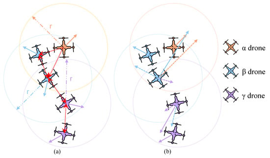
Figure 2.
Various relationships between drones. (a) Definition of different layers of drones and the interaction topology diagram between drones. (b) Vector synthesis of drone velocity. In (a), the direction of the red dashed arrow represents the information flow direction. In (b), the length of the dotted line represents the contribution intensity. The drone does not contribute to its new preferred movement direction.
In the model, the movement direction of the drone will not be affected by any other drone. For drones of other layers, all members excluding themselves have the ability to influence their movement directions. The flows of direction information among drones are shown in the Figure 2a. Only when the information of a certain drone flows to a given drone, can it contribute to the given drone. WVEM has its dominance matrix , in which the element follows the rule,
Besides, , thereby is also called a strictly dominance matrix.
Furthermore, we hope to increase the system convergence speed by weighting drones. The same weight is assigned to the drones of the same layer, and the drones of different layers are assigned with different weights. The drone is assigned with weight , drones are assigned with , and drones are assigned with . WVEM has its contribution matrix , in which the element follows the rule,
The value of weighting plays a significant role in system performance. In the system evolution, the heading angle of the drone is exactly the reference state. A drone is directly influenced by the drone, so that it aligns with the drone more quickly and its direction is closer to the reference state than the drone. The closer the drone movement direction is to the reference state, the higher the assigned weight value to encourage all drones to align with the reference state faster. Therefore, there should be . Its rationality is verified, and more beneficial weighting guidelines have been researched by experiments since. To simplify the model, without loss of generality, let in this paper, which means that the contribution intensity of the drone is regarded as a benchmark for other drones.
The drones in WVEM have the same kinematic model as VEM. The updated model of drones heading angles is as follows and is shown in Figure 2b:
where
and refers to the angle obtained by the drone after adjusting its angle according to the path information that it masters.
3.2. Layer Regulation Mechanism
As long as the drone is identified, the layers of other drones can also be determined, which denotes that the identification of the drone is the most important. Whoever masters the information conducive to the flock’s survival becomes the drone. The setup of the drone is related to the specific scenario encountered by the flocking. This paper mainly focuses on two actual scenarios:
- Scenario (I), Flocking Navigation. This refers to the process where the flocking movement is prompted by the drone that masters the predetermined trajectory.
- Scenario (II), Obstacle Avoidance. This refers to the process where the flocking movement is prompted by the drones that detect the obstacle.
The scenario matrix represents the scenario information mastered by each drone, and the matrix element follows the rule,
where means that drone i knows the trajectory information, and means that i does not know. Thereby, the definition of the drone is as follows:
The behavior of the drone is to adjust its heading angle , which is exactly the reference state of the flocking. For specific scenarios, the drone has different behavior strategies:
- In scenario (I), the drone acts to move along the trajectory .
- In scenario (II), the drone acts to stay away from the obstacle .
Different scenarios possess different degrees of importance. When the drone is in comprehensive scenarios, it takes the action that should be taken assuming the most important scenario. For the flocking survival, obstacle avoidance is more important, and the drone takes action to stay away from the obstacle if finding the objective and obstacle at the same time,
During the flocking movement, the abrupt scenario appears randomly, while an immutable layer of the drone cannot address it appropriately. Hence, the layer regulation mechanism for the drone is proposed in response to the abruptness and randomness of the scenario. The layer regulation mechanism only refers to the mutual transformation of non- drones and the drone, and the layers of other drones are transformed accordingly. For a navigating flock who suddenly detects obstacle, the regulation mechanism includes two rules:
- If a non- drone detects the objective or obstacle, it immediately transforms into an drone and takes corresponding actions required by the specific scenario. For the drone, only if it detects the obstacle during the process of moving to the objective does it change its action to stay away from the obstacle; otherwise, it maintains the previous behavior.
- For the drone that previously detected the obstacle and is no longer detecting the obstacle, if it does not master the objective location, it is transformed into a non- drone and its identity is determined with (7) and (8), otherwise it is also an drone and only changes behavior.
3.3. WVEM-Based Flocking Algorithm
VEM is the solution to the rule of velocity matching and provides the alignment term. To achieve complete flocking navigation, it is still necessary to add attraction term and repulsion term for the drone swarm [13,14]. The attraction force is used to maintain the swarm compactness and the repulsion force is to avoid the collision. The form of the attraction term is as follows:
where represents the range of the attraction force, represents the range of the repulsion force, and satisfies . The form of the repulsion term is as follows:
where satisfies . The intensities of both terms of the drones of all layers to other drones are the same and the drone is still not influenced by any other drone. The velocity of the drone is updated according to the following equations:
where represent the coefficients of the alignment term, the repulsion term, and the attraction term, respectively, and represents the max velocity magnitude of the drone, .
Accordingly, the process of the WVEM-based flocking algorithm is summarized as Algorithm 1.
| Algorithm 1: WVEM-based flocking algorithm |
|
4. Numerical Simulation and Analysis
This section firstly verifies whether all drones converge to the reference state with the drone in a fixed movement direction. Next, the factors affecting the model alignment performance are analyzed in detail. Then, the flocking navigation and better avoidance of abrupt are realized in the presence of noise, which verifies the robust performance and practical value of the model.
4.1. The Verification of Alignment with the Drone
This section mainly observes whether all drones can converge to the fixed direction, which is the foundation of achieving flocking navigation. The attraction term and repulsion term are ignored and the experiments are conducted in the periodic boundary environment. We use convergence time as a performance metric to evaluate system performance. denotes the minimum time steps required for the system to reach the desired consistency degree . represents the consistency degree between all drones’ heading angles and the reference state,
where represents the reference state and represents the quantity of the drone. Accordingly, is expressed as follows;
where ; the higher , the more severe consistency degree required by the system. The shorter , the faster convergence speed and the better performance.
In these experiments, the reference state is set to . There is one drone whose heading angle is always , with an initial position that is in the lower-left corner of the area. To stress the feasibility of the alignment to the reference state as the focus of our study, this section dose not consider any noise temporarily. The parameter settings are as follows: . The process of system evolution is shown in Figure 3.
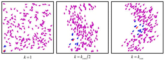
Figure 3.
System circumstance at different time steps under different groups. The red drone represents the drone, blue represents drones, and purple represents drones. The drones are almost within a certain range around the drone.
Figure 3 shows the drones transforming from the initial chaos and disorder to the final alignment with the drone, vividly illustrating the feasibility. As shown in Figure 4, the movement directions of all drones converge to the reference state and the consistency degree gradually tends to 1, which also demonstrates the reliability of WVEM.
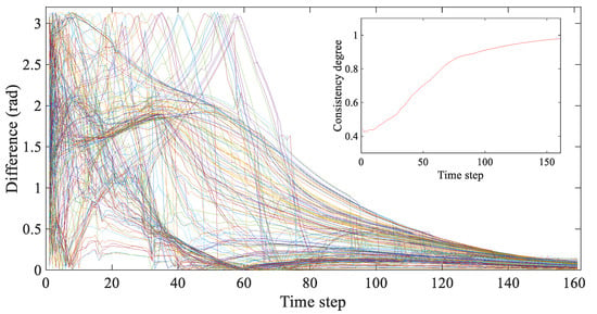
Figure 4.
The difference between the movement direction of each drone and the reference state at each time step. The curves of different color display the trend of different drone. The inset shows the consistency degree of the swarm at each time step.
Besides, to verify the significance of WVEM, we compare it with two baseline models, i.e., the classic Vicsek model (VEM) and the classic Vicsek model with one drone (VEM-). The initial position and velocity of drone also influence the convergence performance, thereby the 100 simulations with different initial states are carried out for each model to avoid the randomness and obtain the general results. Three sets of groups are discussed: . The results are shown in Table 1.

Table 1.
The alignment performance of each model.
As shown in Table 1, VEM- can induce the swarm to converge to the reference state while the swarm inspired by VEM cannot. The only difference between VEM- and VEM is drone, which suggests that the drone is the foundation for the swarm to converge to the reference state. The direction of the drone is not affected by other drones. Other drones are constantly directly or indirectly affected by the drone, leading to the tendency that they align with the drone and eventually align to the reference state.
Compared with VEM-, the convergence time of WVEM with is significantly shorter. VEM- is a special case of WVEM, specifically referring to the case of , which means that in the swarm, all drones posses the same contribution intensities. The superior system performance of WVEM demonstrates that the weighting mechanism can improve the speed of the alignment of all drones to the reference state.
4.2. Analysis of Factors Affecting Alignment Performance
This section analyses the factors affecting the alignment performance. There are many factors that affect the system convergence time due to numerous parameters involved in WVEM—these include, but not limited to, weighting values, quantity and location of the drone, drone interaction radius, drone density, noise intensity and type, consistency degree requirement, limited field of view, drone velocity, and other factors. Among these factors, weighting is regarded as the highlight of this paper. We firstly explore the influence of weighting values on the model performance. Then, we discuss how the drone interaction radius influences the performance. The attraction term and repulsion term are also ignored and the experiments are conducted in the periodic boundary environment. There is one drone whose heading angle is always and initial position is the lower-left corner of the area in the system.
4.2.1. Impacts of Weighting Values
To initially analyze the impact of weighting values on the performance with changing, let . The other parameter settings are as follows: . Experiments of different initial states are conducted 100 times for different to obtain the general conclusions. The results are shown in Figure 5.
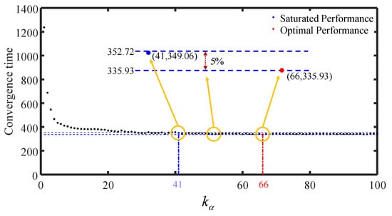
Figure 5.
The average convergence time of 100 trials. The blue point indicates that the system performance has reached saturation and the red indicates that the system performance has reached optimal. The upper, blue dashed line ordinate is 352.72, on the lower side of which the blue point has the smallest abscissa. The lower line has ordinate 335.93 and passes through the red point. All of the points behind the blue point are between the two dashed lines.
As shown in Figure 5, the general trend is that the convergence time decreases with increasing. The drone holds larger contribution intensity to induce other drones to align with it more quickly, which allows better system performance. Before , the system convergence time decreases strictly. From , the system convergence time begins to fluctuate. When , the system has the shortest convergence time and optimal performance.
From to , none of the convergence time exceeds the of optimal convergence and the performance does not change significantly, which means the influence of the drone on surrounding drones has reached saturation at . When the surrounding drones receive the information of the drone, although there is interference from drones and other drones, they can take the fastest action to align with the drone. Even if the weight of the drone is further increased, the surrounding drones cannot take faster action. The existence of fluctuation is because the flocking is probabilistic but not too large—as mentioned, it does not exceed . The more numerical simulations, the smaller the fluctuation. On the other hand, the number of drones within the interaction range of the drone is limited due to the limitation of drone density, which constrains the drone from influencing more drones in a given time. Consequently, although continues to increase, the model’s performance cannot be further improved. At this moment, it is essential to adjust the value of to improve model performance.
To further study the influence of weighting values on model performance, we simultaneously adjust the values of and to observe system performance. The results are as shown in Figure 6 and Table 2.
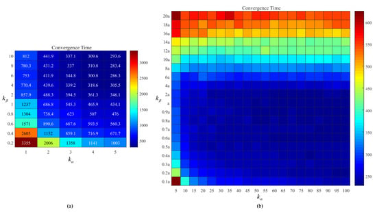
Figure 6.
The average convergence time of 100 simulations under different weighting values. (a) Smaller weighting values. (b) Larger weighting values. The value of in (a) is absolute, while in (b) it is relative to the value of .

Table 2.
System performance.
Figure 6a shows that appropriate parameter settings reduce the convergence time greatly compared with the case of . Weighting distinctly improves the system performance, which demonstrates its feasibility and significance. Besides, for any fixed , the system performance with is superior to , which verifies the rationality of .
For any fixed , the general trend is that the convergence time decreases as increases, which is consistent with the result shown in Figure 5. The movement direction of the drone is the reference state, and the increase of its contribution intensity does not produce any interference information to the system or increase the weight of interference. The continuing increase of only becomes meaningless due to the existence of saturated performance, but does not negatively affect system performance.
For fixed , when is relatively small, the convergence time decreases as increases. Compared with drones, the proximity of the heading angle of drones to the reference state is higher. When a drone owns higher contribution intensity, it induces other drones to converge to the reference state more quickly. When b continues to increase, the system performance begins to fluctuate and there is no significant increase. Similar to the drone, performance fluctuation and saturated performance are also adopted by the drone. As shown in Figure 6b, when , the system possesses global optimal performance, while when , the system has achieved global saturation performance. For any fixed value of , the system has obtained local saturation performance when . Therefore, it is not necessary for the drone and drones to be assigned with extremely large values because of the existence of the saturation performance, and it is sufficient that .
Furthermore, when —specifically, —the system convergence time increases sharply with increasing. For a given drone, besides the drone, other drones in the interaction range also affect its movement direction. The movement direction of a drone may be far from the reference state, and the increase of implies the improvement of the contribution intensity of possible interference information. The influence of the movement information of the drone on the system becomes relatively insignificant due to the larger intensity of other interference information, and given that drones and drones align more slowly. Although the drone induces the drone to align with it faster, the current movement direction of the drone is not necessarily the exact reference state, which is not only meaningless but also may seriously reduce the system performance. Therefore, it is inappropriate that .
Accordingly, to a certain extent, the rationality of has been successfully proved.
4.2.2. Impacts of Interaction Radius
This section mainly discusses the influence of interaction radius on the model. Let , . The results are shown in Figure 7 and Figure 8.
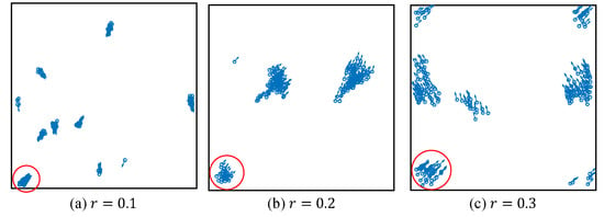
Figure 7.
The system evolution after 1000 time-steps under different, too short interaction radii. All drones are divided into many clusters. The drone induces the cluster in the red circle to converge to the reference state successfully.
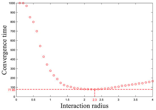
Figure 8.
Average convergence time of 100 simulations with different initial states. To reduce computational burden, the upper limit of time step is 1000.
Figure 7 presents many clusters instead of a whole flocking under , and , although after a long enough operation time. The drone induces only a few drones to converge to the reference state, because too small an interaction radius limits the influence range of the drone and the system is not globally connected. Most drones do not establish direct or indirect interaction with the drone from start to finish, thereby they do not align with the drone. The system only spontaneously forms several small clusters with their own unpredictable direction. Therefore, the whole system is unable to converge to the reference state.
As shown in Figure 8, when , the convergence time decreases as the interaction radius increases. The drones that align with the drone equivalently master the reference state. With the interaction radius increasing, more drones are capable of interacting with the drone or the drones that master the reference state. This means that information of the reference state holds a larger influence range and a rapider transmission efficiency, and all drones are able to interact with the reference state in a shorter time. Therefore, the drones converge to the reference state more quickly.
Furthermore, when , the larger the interaction radius, the longer the convergence time, which is contrary to our ordinary perception. This is because the correction efficiency of the drone angle is reduced. Correction efficiency refers to the time taken for a drone to align to the reference state after interacting with drones that have mastered the reference state and depends on the intensity of the reference state relative to other interference information. The movement directions of drones and drones are determined by the movement direction of the surrounding drones. It is impossible for all the surrounding drones to align with the drone; the larger the drone interaction radius, the more interference information the drone may receive. If the contribution intensity of the reference state is not large enough, the drones are more likely to be induced by interference information, thus, increasing the convergence time. Considering this, the system performance can be further improved by adjusting and .
Therefore, an optimal interaction radius exists when other settings are fixed. is the optimal radius under the current settings.
4.3. Flocking Navigation and Obstacle Avoidance
This section mainly verifies whether the swarm can achieve flocking navigation according to the WVEM-based flocking algorithm and if better obstacle avoidance can be realized.
4.3.1. The Performance of Flocking Navigation
As long as the movement direction of each drone aligns with the drone within a short enough time, the drone swarm can move along the predetermined trajectory. This paper considers the flock composed of 15 drones, among which there is one drone. The attraction term and repulsion term are added and the periodic boundaries removed. In this section, a certain amount of noise is added; let . At the initial moment, the coordinates of the drone are (0.9585,0.9585); both abscissa and ordinate of each drone obey a [0,1.9170] uniform distribution, and the heading angle obeys uniform distribution. The drone moves along a rectangular trajectory. The results are shown in Figure 9.
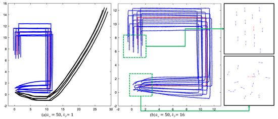
Figure 9.
The trajectories of all drones. The red line shows the trajectory of the drone. The blue lines represent the drones that move along the predetermined trajectory. The black lines indicate drones that have deviated from the predetermined trajectory.
In Figure 9a, ; in Figure 9b, . Figure 9a shows that some drones detach from the flocking and do not move along the predetermined trajectory, exposing the failure of flocking navigation. Figure 9b shows that in the presence of noise, all drones always align with and follow the drone closely and move along the predetermined trajectory, which means the system achieves flocking navigation successfully and acquires a certain degree of robustness. To eliminate the influence of noise on system performance and obtain the general conclusions, ten trials of experiments are carried out for each set of parameter settings. For , the average number of drones that can move along the predetermined trajectory is 10; for , the average number is 15; all drones can achieve flocking navigation. It is obvious that a suitable weighting value plays a significant role for WVEM. The flocking navigation can be achieved based on WVEM if the parameter settings are appropriate.
4.3.2. The Performance of Obstacle Avoidance
In this paper, the layer regulation mechanism is an approach to improve the survival of the swarm when detecting the obstacle, rather than a specific avoidance mechanism. Therefore, the simple obstacle and corresponding avoidance mechanism are set, which are enough to verify the effectiveness of the layer regulation mechanism.
In this section, there is an infinitely long obstacle parallel to the y-axis at . The detection radius of the drone is equal to the interaction radius, . For drone i, when , it can detect the obstacle and adjust its movement direction to . When the layer regulation mechanism is applicable, if drones or drones detect the obstacle, they become drones and own the reference state ; if drones detect the obstacle, they adjust reference state . When the layer regulation mechanism is not applicable, if drones or drones detect the obstacle, their layers remain the same and they are still influenced by repulsion terms and attraction terms of other drones. Let , . At the initial moment, the coordinates of the drone are (0.0959,0.0959), both abscissa and ordinate of other drones obey a [0,1.9170] uniform distribution, and the heading angles of all drones are 0. The results are shown in Figure 10.
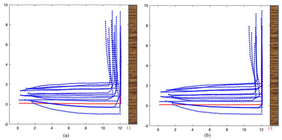
Figure 10.
The trajectories of all drones under different conditions. (a) Applying layer regulation mechanism. (b) Not applying layer regulation mechanism.
Figure 10 presents, in the presence of noise, the success of obstacle avoidance, during which no drone appears . When drones detect the obstacle, the faster the movement direction of the flocking converges to the reference state, the further the drones are away from the obstacle, and the safer the drones are. To evaluate the system performance in detail, the average distance between all drones and the obstacle within a certain period of time is proposed, which is calculated as follows:
where . The last 20 time-steps are selected for calculations. In Figure 10a, the layer regulation mechanism is applied, Dis; in Figure 10b, the layer regulation is not applied, Dis. It is obvious that the safe distance with the layer regulation mechanism is larger than without the mechanism. More drones becoming drones can possess greater contribution intensity to induce the whole flocking to move in the direction conducive to survival. Therefore, the appropriate application of the layer regulation mechanism can improve system performance, and its robustness and practical value are verified.
5. Conclusions
This paper proposes WVEM based on VEM to achieve flocking navigation with only one drone mastering the path information. First, WVEM introduces the drone, which occupies two characteristics: the specific movement direction and immunity to any other drone. It is verified that the existence of the drone is the fundamental condition to achieve flocking navigation. Then, all drones are divided into three layers dynamically based on the interaction topology and the drones at different layers are assigned with different weights. The weighting rule is put forward to improve the alignment performance and has been proved through experiments. In addition, a detailed analysis about the influence of interaction radius on model performance is conducted. Then, the layer regulation mechanism is proposed to achieve the flexible obstacle avoidance. Thereby, the flocking navigation and obstacle avoidance composed of 15 drones are achieved, which confirm the reliability of the proposed model and the effectiveness of proposed mechanisms. In the future, we will map the settings to the real world, design a better approach to define the layers and assign weights to improve the model performance, and propose better order parameters to analyze flocking performance.
Author Contributions
Conceptualization, X.X.; Data curation, D.T.; Formal analysis, C.Y.; Funding acquisition, H.Z.; Investigation, X.L.; Methodology, Y.C.; Project administration, Y.C.; Resources, X.X.; Software, X.L.; Supervision, H.Z.; Validation, X.L.; Visualization, X.L. and C.Y.; Writing—original draft, X.L.; Writing—review & editing, Y.C., C.Y. and H.Z. All authors have read and agreed to the published version of the manuscript.
Funding
This research was supported by National Nature Science Foundation under grant 61803377.
Data Availability Statement
Not appliable.
Conflicts of Interest
The authors declare they have no conflict of interest.
References
- Parrish, J.; Edelstein-Keshet, L. Complexity, pattern, and evolutionary trade-offs in animal aggregation. Science 1999, 284, 99–101. [Google Scholar] [CrossRef] [PubMed]
- Couzin, I. Collective minds. Nature 2007, 445, 715. [Google Scholar] [CrossRef] [PubMed]
- Vicsek, T.; Zafeiris, A. Collective motion. Phys. Rep. 2012, 517, 71–140. [Google Scholar] [CrossRef] [Green Version]
- Beaver, L.E.; Malikopoulos, A.A. An Overview on Optimal Flocking. arXiv 2020, arXiv:abs/2009.14279. [Google Scholar]
- Hayes, A.T.; Dormiani-Tabatabaei, P. Self-organized flocking with agent failure: Off-line optimization and demonstration with real robots. In Proceedings of the IEEE International Conference on Robotics & Automation, Washington, DC, USA, 11–15 May 2002. [Google Scholar]
- Zhou, H.; Zhao, H.; Han, T.; Huang, H.Q. Cooperative flight and evasion control of uav swarm based on rules. Syst. Eng. Electron. 2016, 38, 1374–1382. [Google Scholar]
- Hoang, D.; Tran, D.M.; Tran, T.S.; Pham, H.A. An adaptive weighting mechanism for reynolds rules-based flocking control scheme. Peerj Comput. Sci. 2021, 7, e388. [Google Scholar] [CrossRef] [PubMed]
- Vicsek, T.; Czirók, A.; Ben-Jacob, E.; Cohen, I.; Shochet, O. Novel type of phase transition in a system of self-driven drones. Phys. Rev. Lett. 1995, 75, 1226–1229. [Google Scholar] [CrossRef] [PubMed] [Green Version]
- Baglietto, G.; Albano, E.V.; Candia, J. Gregarious versus individualistic behavior in vicsek swarms and the onset of first-order phase transitions. Phys. A Stat. Mech. Appl. 2013, 392, 3240–3247. [Google Scholar] [CrossRef] [Green Version]
- Netzer, G.; Yarom, Y.; Ariel, G. Heterogeneous populations in a network model of collective motion—Sciencedirect. Phys. A Stat. Mech. Appl. 2019, 530, 121550. [Google Scholar] [CrossRef]
- Xue, T.; Li, X.; Grassberger, P.; Chen, L. Swarming transitions in hierarchical societies. Phys. Rev. Res. 2020, 2, 042017. [Google Scholar] [CrossRef]
- Jia, Y.; Vicsek, T. Modelling Hierarchical Flocking. New Phys. Soc. 2019, 21, 093048. [Google Scholar] [CrossRef]
- Vásárhelyi, G.; Virágh, C.; Somorjai, G.; Tarcai, N.; Szörényi, T.; Nepusz, T.; Vicsek, T. Outdoor flocking and formation flight with autonomous aerial robots. In Proceedings of the 2014 IEEE/RSJ International Conference on Intelligent Robots and Systems, Chicago, IL, USA, 14–18 September 2014; pp. 3866–3873. [Google Scholar]
- Reynolds, C.W. Flocks, Herds, and Schools: A Distributed Behavioral Model. In Proceedings of the 14th Annual Conference on Computer Graphics and Interactive Techniques, Anaheim, CA, USA, 27–31 July 1987; pp. 25–34. [Google Scholar] [CrossRef] [Green Version]
Publisher’s Note: MDPI stays neutral with regard to jurisdictional claims in published maps and institutional affiliations. |
© 2021 by the authors. Licensee MDPI, Basel, Switzerland. This article is an open access article distributed under the terms and conditions of the Creative Commons Attribution (CC BY) license (https://creativecommons.org/licenses/by/4.0/).